Embed Size (px)
Citation preview
Meridian 1
Line Cards Description
Document Number: 553-3001-105Document Release: Standard 6.00Date: April 2000
Year Publish FCC TM
Copyright © 1994–2000 Nortel NetworksAll Rights Reserved
Printed in Canada
Information is subject to change without notice. Nortel Networks reserves the right to make changes in design or components as progress in engineering and manufacturing may warrant. This equipment has been tested and found to comply with the limits for a Class A digital device pursuant to Part 15 of the FCC rules, and the radio interference regulations of Industry Canada. These limits are designed to provide reasonable protection against harmful interference when the equipment is operated in a commercial environment. This equipment generates, uses and can radiate radio frequency energy, and if not installed and used in accordance with the instruction manual, may cause harmful interference to radio communications. Operation of this equipment in a residential area is likely to cause harmful interference in which case the user will be required to correct the interference at their own expense.
SL-1 and Meridian 1 are trademarks of Nortel Networks.
Line Cards Description

Page 3 of 252
4
se ces
nces
0AA
1
ical
Revision historyApril 2000
Standard 6.00. This is a global document and is up-issued for X11 Relea25.0x. Document changes include removal of: redundant content; referento equipment types except Options 11C, 51C, 61C, and 81C; and refereto previous software releases.
June 1999Standard, release 5.00.
October 1997Standard, release 4.00. This document is reissued to include the NT5D6CLASS Modem Card (XCMC).
August 1996Standard, release 3.00. This document is reissued to include the NT5D1Line-side T1 Interface Card.
July 1995Standard, release 2.00. This document is reissued to incorporated techncorrections.
December 1994Standard, release 1.00. This is the initial release of this document. It supersedes:
• NT8D02 Digital Line Card description (553-3001-162)
• NT8D09 Analog Message Waiting Line Card description (553-3001-163)
• 500/2500 line cards description and operation (553-2201-183)
• QPC578 Integrated Services Digital Line Card description (553-2201-193)
Line Cards Description
Page 4 of 252
se
This document also contains information on the new NT1R20 Off-premiStation Analog Line Card.553-3001-105 Standard 6.00 April 2000
Page 5 of 252
6
Contents
About this document . . . . . . . . . . . . . . . . . . . . . . . 7
Description . . . . . . . . . . . . . . . . . . . . . . . . . . . . . . . . 9
NT1R20 Off-Premise Station Analog Line Card . . 45
NT5D11 Line-side T1 Interface Card . . . . . . . . . . . 67
NT5D33 and NTRB34 Line-sideE1 Interface Cards . . . . . . . . . . . . . . . . . . . . . . . . . . 125
NT5D60AA CLASS Modem Card (XCMC) . . . . . . . 185
NT8D02 Digital Line Card . . . . . . . . . . . . . . . . . . . . 193
NT8D09 Analog Message Waiting Line Card . . . . 209
NTRD24 24-Port Digital Line Card . . . . . . . . . . . . . 227
List of terms . . . . . . . . . . . . . . . . . . . . . . . . . . . . . . . 243
Index . . . . . . . . . . . . . . . . . . . . . . . . . . . . . . . . . . . . . 247
Line Cards Description

Page 6 of 252 Contents
553-3001-105 Standard 6.00 April 2000
Page 7 of 252
8
ur
ed ded
About this documentThis document is a global document. Contact your system supplier or yoNortel Networks representative to verify that the hardware and software described is supported in your area.
This document outlines the functions, specifications, applications, and operation of the various Meridian 1 line cards. This information is intendto be used as a guide when connecting the line cards to customer-provistation equipment.
ReferencesSee the Meridian 1 System planning and engineering guide for
• System Engineering (553-3001-151)
• Spares Planning (553-3001-153)
• Equipment Identification (553-3001-154)
• Summary of Transmission Parameters (553-2201-182)
See the Meridian 1 System installation and maintenance guide for
• System Installation Procedures (553-3001-210)
• Circuit Card: Installation and Testing (553-3001-211)
• General Maintenance Information (553-3001-500)
• Fault Clearing (553-3001-510)
• Hardware Replacement (553-3001-520)
Line Cards Description
Page 8 of 252 About this document
in
See the X11 software guide for an overview of software architecture, procedures for software installation and management, and a detailed description of all X11 features and services. This information is containedtwo documents:
• X11 System Management (553-3001-300)
• X11 Features and Services (553-3001-306)
See the X11 Administration (553-3001-311) for a description of all administration and maintenance programs, and X11 System Messages Guide (553-3001-411) for information about system messages.
553-3001-105 Standard 6.00 April 2000
Page 9 of 252
44
DescriptionContent list
The following are the topics in this section:
• Overview 10
• Select a line card 11
• Intelligent peripheral equipment line cards 12
• Installation 14
• Operation 16
• Host interface bus 16
• Analog line interface units 22
• Digital line interface units 25
• Analog line call operation 27
• Digital line call operation 33
• Line-side T1 call operation 33
• Voice frequency audio level 41
• Off-premise line protection 41
• Line protectors 42
• Line protection grounding 42
• Line and telephone components 44
Line Cards Description
Page 10 of 252 Description
ons
Reference listThe following are the references in this section:
• System Engineering (553-3001-151)
• System Installation Procedures (553-3001-210)
• Circuit Card: Installation and Testing (553-3001-211)
• X11 Administration (553-3001-311)
OverviewThis document describes the various line cards that are used with the Meridian 1 switch. It shows how the line cards fit into the Meridian 1 architecture, how they are used at the customer site, and how they are installed and programmed. It then provides detailed technical specification each of the cards.
This document describes six line cards:
• NT1R20 Off-Premise Station Analog Line Card
• NT5D11 Line-side T1 Interface Card
• NT5D33 and 34 Line-Side E1 Interface Card
• NT8D02 Digital Line Card
• NT8D09 Analog Message Waiting Line Card
• NTRD24 24-port Digital Line Card
553-3001-105 Standard 6.00 April 2000
Description Page 11 of 252
will
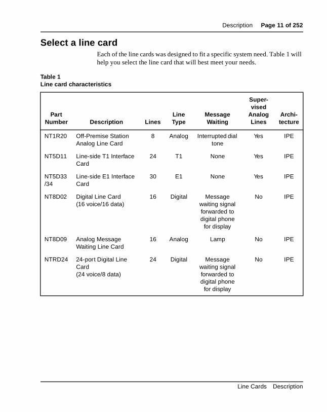
Select a line cardEach of the line cards was designed to fit a specific system need. Table 1help you select the line card that will best meet your needs.
Table 1Line card characteristics
PartNumber Description Lines
LineType
MessageWaiting
Super-vised
Analog Lines
Archi-tecture
NT1R20 Off-Premise StationAnalog Line Card
8 Analog Interrupted dial tone
Yes IPE
NT5D11 Line-side T1 Interface Card
24 T1 None Yes IPE
NT5D33/34
Line-side E1 Interface Card
30 E1 None Yes IPE
NT8D02 Digital Line Card(16 voice/16 data)
16 Digital Message waiting signal forwarded to digital phone
for display
No IPE
NT8D09 Analog MessageWaiting Line Card
16 Analog Lamp No IPE
NTRD24 24-port Digital Line Card(24 voice/8 data)
24 Digital Message waiting signal forwarded to digital phone
for display
No IPE
Line Cards Description
Page 12 of 252 Description
stem
nt
to
the
es flash
ital
key rs
as rd to
an
Intelligent peripheral equipment line cardsThe following line cards are designed using the Intelligent Peripheral Equipment (IPE) architecture and are recommended for use in all new sydesigns.
NT1R20 Off-Premise Station Analog Line CardThe NT1R20 Off-Premise Station (OPS) Analog Line Card is an intelligeeight-channel analog line card designed to be used with 2-wire analog terminal equipment such as analog (500/2500) telephones and analog modems. Each line has integral hazardous and surge voltage protectionprotect the Meridian 1 system from damage due to lightning strikes and accidental power line connections. This card is normally used wheneverphone lines have to leave the building in which the Meridian 1 switch is installed. The OPS line card supports message waiting notification by interrupting the dial tone when the receiver is first picked up. It also providbattery reversal answer and disconnect analog line supervision and hookdisconnect analog line supervision features.
NT5D11 Line-side T1 Interface CardThe NT5D11 Line-side T1 Interface Card is an intelligent 24-channel digline card that is used to connect the Meridian 1 switch to T1 compatible terminal equipment on the line-side. T1 compatible terminal equipment includes voice mail systems, channel banks containing FXS cards, and systems such as the Nortel Networks Norstar. The line-side T1 card diffefrom trunk T1 cards in that it supports terminal equipment features suchhook-flash, transfer, hold, and conference. It emulates an analog line cathe Meridian 1 software.
NT5D33 and 34 Line-side E1 Interface CardThe NT5D33/34 Line-side E1 Interface Card is an intelligent 30-channeldigital line card that is used to connect the Meridian 1 switch to E1 compatible terminal equipment on the line-side. E1 compatible terminal equipment includes voice mail systems. The line-side E1 card emulatesanalog line card to the Meridian 1 software.
553-3001-105 Standard 6.00 April 2000
Description Page 13 of 252
rd pair
nel h as also
ch ture.
NT8D02 Digital Line CardThe NT8D02 Digital Line Card is an intelligent 16-channel digital line cathat provides voice and data communication links between a Meridian 1switch and modular digital telephones. Each of the 16 channels supportvoice-only or simultaneous voice and data service over a single twisted of standard telephone wire.
NT8D09 Analog Message Waiting Line CardThe NT8D09 Analog Message Waiting Line Card is an intelligent 16-chananalog line card designed to be used with 2-wire terminal equipment sucanalog (500/2500) telephones, modems, and key systems. This card canprovide a high-voltage, low-current signal on the Tip and Ring pair of ealine to light the message waiting lamp on phones equipped with that fea
NTRD24 Analog Message Waiting Line CardThe NTRD24 24-Port Digital Line Card (EDLC) provides an alternative configuration to the existing NT8D02 16-Port Digital Line Card (XDLC). The EDLC provides 24 voice units and 8 data units.
Line Cards Description
Page 14 of 252 Description
ne
lot
e.
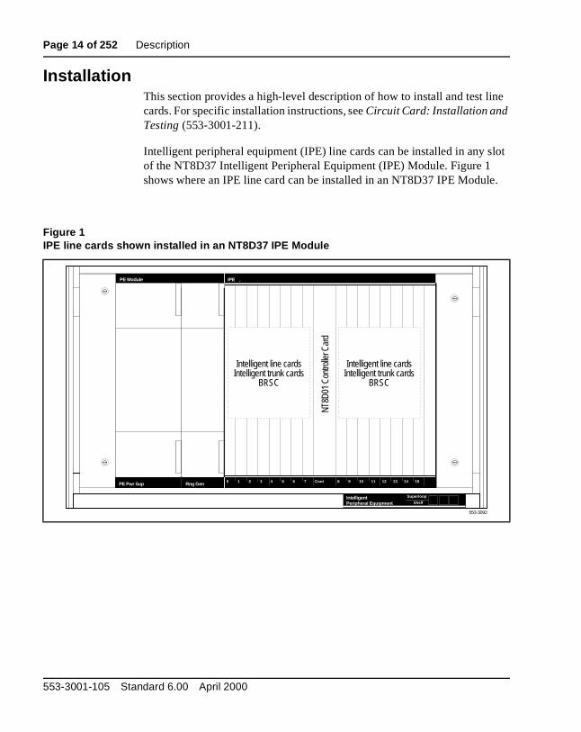
InstallationThis section provides a high-level description of how to install and test licards. For specific installation instructions, see Circuit Card: Installation and Testing (553-3001-211).
Intelligent peripheral equipment (IPE) line cards can be installed in any sof the NT8D37 Intelligent Peripheral Equipment (IPE) Module. Figure 1 shows where an IPE line card can be installed in an NT8D37 IPE Modul
Figure 1IPE line cards shown installed in an NT8D37 IPE Module
IntelligentPeripheral Equipment
Superloop
Shelf
IPEPE Module
PE Pwr Sup Rng Gen
Intelligent line cardsIntelligent trunk cards
BRSC
Intelligent line cardsIntelligent trunk cards
BRSC
NT8D
01 C
ontro
ller C
ard
553-3092
0 2 3 4 5 6 7 Cont 9 11 12 13 151 8 1410
553-3001-105 Standard 6.00 April 2000
Description Page 15 of 252
our
ain
e
y
When installing line cards, these general procedures should be used:
• Configure the jumpers and switches on the line card (if any) to meet ysystem needs.
• Install the line card into the slot you have selected.
• Install the cable that connects the backplane connector on the IPE module to the module I/O panel.
• Connect a 25-pair cable from the module I/O panel connector to the mdistribution frame (MDF).
• Connect the line card output to the selected terminal equipment at thMDF.
• Configure the individual line interface unit using the Single-line Telephone Administration program (LD 10) for analog line interface units and Multi-line Telephone Administration program (LD 11) for digital line interface units.
Once these steps have been completed, the terminal equipment is readfor use.
Line Cards Description
Page 16 of 252 Description
the ct to
the , and
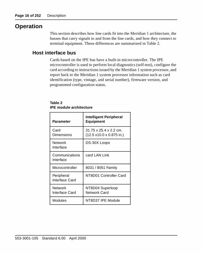
OperationThis section describes how line cards fit into the Meridian 1 architecture,busses that carry signals to and from the line cards, and how they conneterminal equipment. These differences are summarized in Table 2.
Host interface busCards based on the IPE bus have a built-in microcontroller. The IPE microcontroller is used to perform local diagnostics (self-test), configure card according to instructions issued by the Meridian 1 system processorreport back to the Meridian 1 system processor information such as cardidentification (type, vintage, and serial number), firmware version, and programmed configuration status.
Table 2IPE module architecture
ParameterIntelligent PeripheralEquipment
Card Dimensions
31.75 x 25.4 x 2.2 cm.(12.5 x10.0 x 0.875 in.)
Network Interface
DS-30X Loops
Communications Interface
card LAN Link
Microcontroller 8031 / 8051 Family
PeripheralInterface Card
NT8D01 Controller Card
Network Interface Card
NT8D04 Superloop Network Card
Modules NT8D37 IPE Module
553-3001-105 Standard 6.00 April 2000
Description Page 17 of 252
ious
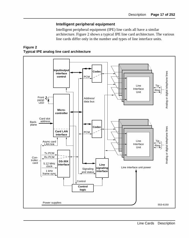
Intelligent peripheral equipmentIntelligent peripheral equipment (IPE) line cards all have a similar architecture. Figure 2 shows a typical IPE line card architecture. The varline cards differ only in the number and types of line interface units.
Figure 2Typical IPE analog line card architecture
Input/outputinterfacecontrol
Codec
PCM
Micro-controller
DS-30Xinterface5.12 MHz
clock
Tx PCM
Async cardLAN link
FrontpanelLED
Card LANinterface
Tip
Ring
Codec
PCM
Line interface unit power
Rx PCM
1 kHzframe sync
Card slotaddressBack-
plane
Con-trollercard
Linesignalinginterface
Controllogic
Signalingand status
Control
Address/data bus
553-6150Power supplies
Ana
log
or d
igita
l tel
epho
ne li
nes
Ana
log
or d
igita
l tel
epho
ne li
nes
Tip
Ring
LineInterface
Unit
LineInterface
Unit
Line Cards Description
Page 18 of 252 Description
te ops,
ations
one
ard, t
ire
ly,
rm
The Meridian 1 switch communicates with IPE modules over two separainterfaces. Voice and signaling data are sent and received over DS-30X loand maintenance data is sent over a separate asynchronous communiclink called the card LAN link.
Signaling data is information directly related to the operation of the telephline. Signaling commands include, but are not limited to the following:
• off-hook/on-hook
• ringing signal on/off
• message waiting lamp on/off
Maintenance data is data relating to the setup and operation of the IPE cand is carried on the card LAN link. Maintenance data includes, but is nolimited to the following:
• polling
• reporting of self-test status
• CP initiated card reset
• reporting of card ID (card type and hardware vintage)
• reporting of firmware version
• downloading line interface unit parameters
• reporting of line interface unit configuration
• enabling/disabling of the DS-30X network loop bus
• reporting of card status or T1 link status
DS-30X loopsThe line interfaces provided by the line cards connect to conventional 2-w(tip and ring) line facilities. IPE analog line cards convert the incoming analog voice and signaling information to digital form and route it to the Meridian 1 common equipment CP over DS-30X network loops. Conversedigital voice and signaling information from the CP is sent over DS-30X network loops to the analog line cards where it is converted to analog foand applied to the line facility.
553-3001-105 Standard 6.00 April 2000
Description Page 19 of 252
its X
the
PE s
her .
Each for bit.
by l is ync
IPE digital line cards receive the data from the digital phone terminal as 512 kHz time compressed multiplexed (TCM) data. The digital line card converts that data to a format compatible with the DS-30X loop and transmit in the next available timeslot. When a word is received from the DS-30loop, the digital line card converts it to the TCM format and transmits it to digital phone terminal over the digital line facility.
A separate dedicated DS-30X network loop is extended between each Iline/trunk card and the controller cards within an IPE module. A DS-30Xnetwork loop is composed of two synchronous serial data buses. One butransports in the transmit (Tx) direction towards the line facility and the otin the receive (Rx) direction towards the Meridian 1 common equipment
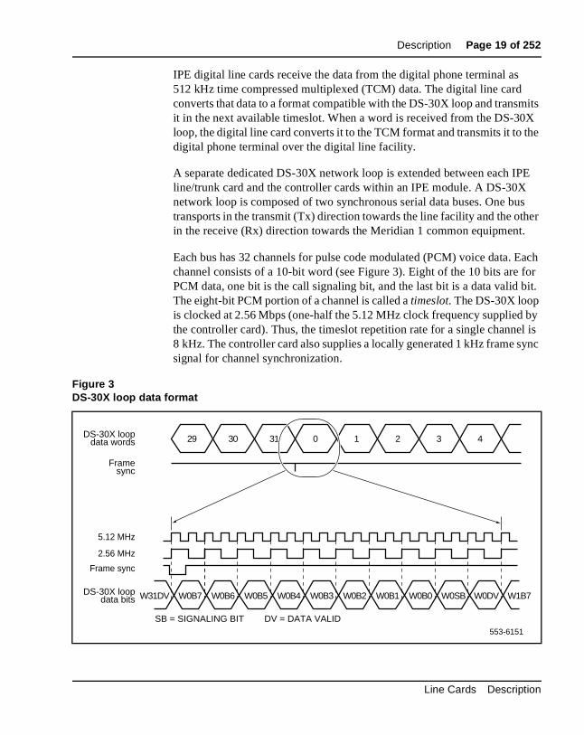
Each bus has 32 channels for pulse code modulated (PCM) voice data. channel consists of a 10-bit word (see Figure 3). Eight of the 10 bits arePCM data, one bit is the call signaling bit, and the last bit is a data valid The eight-bit PCM portion of a channel is called a timeslot. The DS-30X loop is clocked at 2.56 Mbps (one-half the 5.12 MHz clock frequency suppliedthe controller card). Thus, the timeslot repetition rate for a single channe8 kHz. The controller card also supplies a locally generated 1 kHz frame ssignal for channel synchronization.
Figure 3DS-30X loop data format
29
W0B7W31DV
DS-30X loopdata words
Framesync
Frame sync
DS-30X loopdata bits
5.12 MHz
2.56 MHz
SB = SIGNALING BIT DV = DATA VALID
30 31 0 1 2 3 4
W0B6 W0B5 W0B4 W0B3 W0B2 W0B1 W0B0 W0SB W0DV W1B7
553-6151
Line Cards Description
Page 20 of 252 Description
ling the .
e bit
-bit
r to M
rd or n 1
n the
t sed by e at
e
input ve
of
Signaling data is transmitted to and from the line cards using the call signabit within the 10-bit channel. When the line card detects a condition that Meridian 1 switch needs to know about, it creates a 24-bit signaling wordThis word is shifted out on the signaling bit for the associated channel onat a time during 24 successive DS-30X frames. Conversely, when the Meridian 1 switch sends signaling data to the line card, it is sent as a 24word divided among 24 successive DS-30X frames.
DS-30Y network loops extend between controller cards and superloop network cards in the common equipment and function in a manner similaDS-30X loops (see Figure 5). Essentially, a DS-30Y loop carries the PCtimeslot traffic of a DS-30X loop. Four DS-30Y network loops form a superloop with a capacity of 128 channels (120 usable timeslots). See System Engineering (553-3001-151) for more information on superloops.
Card LAN linkMaintenance communications is the exchange of control and status databetween IPE line or trunk cards and the CE CP by way of the NT8D01 Controller Card. Maintenance data is transported via the card LAN link. This link is composed of two asynchronous serial buses (called the Async caLAN link in Figure 2). The output bus is used by the Meridian 1 controller foutput of control data to the line card. The input bus is used by the Meridiacontroller for input of line card status data.
A card LAN link bus is common to all of the line/trunk card slots within aIPE module. This bus is arranged in a master/slave configuration wherecontroller card is the master and all other cards are slaves. The module backplane provides each line/trunk card slot with a unique hardwired sloaddress. This slot address enables a slave card to respond when addresthe controller card. The controller card communicates with only one slava time.
In normal operation, the controller card continually scans (polls) all of thslave cards connected to the card LAN to monitor their presence and operational status. The slave card sends replies to the controller on the bus along with its card slot address for identification. In this reply, the slainforms the controller if any change in card status has taken place. The controller can then prompt the slave for specific information. Slaves onlyrespond when prompted by the controller; they do not initiate exchange control or status data on their own.
553-3001-105 Standard 6.00 April 2000
Description Page 21 of 252
st. the ries
nd
When an IPE line card is first plugged into the backplane, it runs a self-teWhen the self-test is completed, a properly functioning card responds tonext controller card poll with the self-test status. The controller then quefor card identification and other status information. The controller then downloads all applicable configuration data to the line card, initializes it, aputs it into an operational mode.
Line Cards Description
Page 22 of 252 Description
ard, a the t
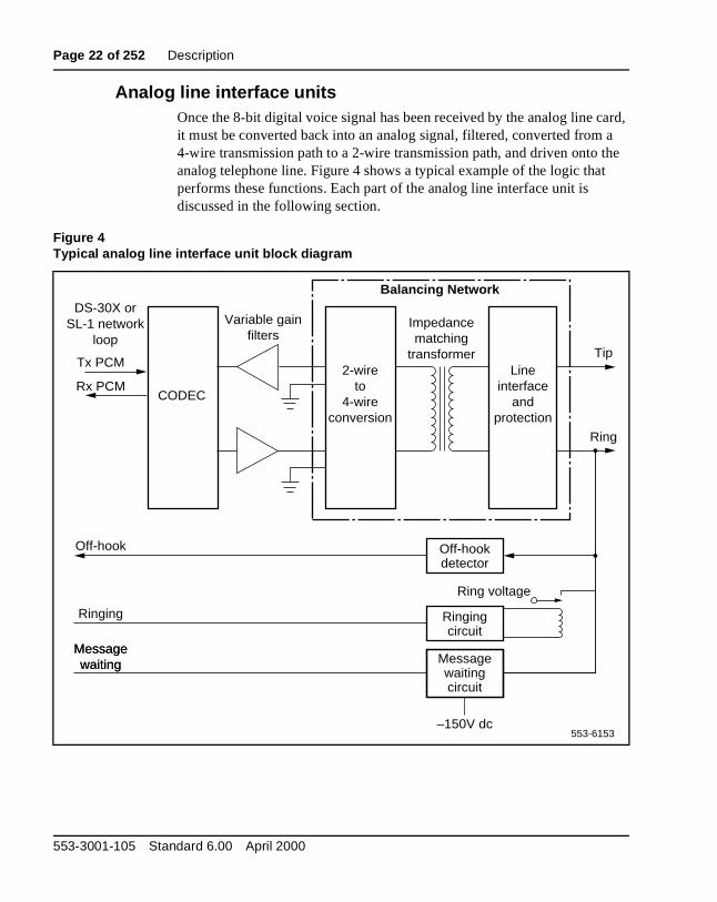
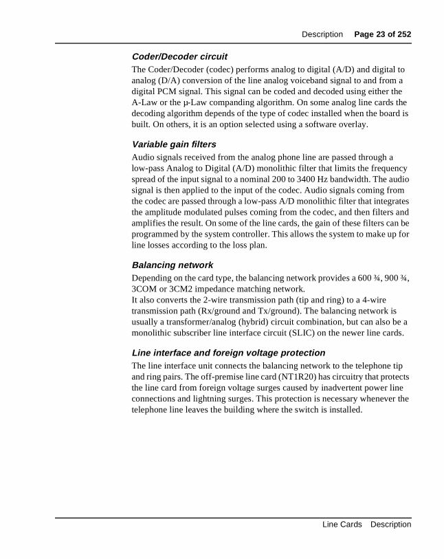
Analog line interface unitsOnce the 8-bit digital voice signal has been received by the analog line cit must be converted back into an analog signal, filtered, converted from4-wire transmission path to a 2-wire transmission path, and driven onto analog telephone line. Figure 4 shows a typical example of the logic thaperforms these functions. Each part of the analog line interface unit is discussed in the following section.
Figure 4Typical analog line interface unit block diagram
CODEC
2-wireto
4-wireconversion
Lineinterface
andprotection
Messagewaiting
Variable gainfilters
Impedancematching
transformer
Balancing Network
Tip
Ring
DS-30X orSL-1 network
loop
Messagewaitingcircuit
–150V dc553-6153
Messagewaiting
Ringingcircuit
Ring voltage
Ringing
Off-hookdetector
Off-hook
Tx PCM
Rx PCM
553-3001-105 Standard 6.00 April 2000
Description Page 23 of 252
to a he he rd is
dio
m ates and n be for
0 ¾,
e a .
tip cts ne r the
Coder/Decoder circuitThe Coder/Decoder (codec) performs analog to digital (A/D) and digital analog (D/A) conversion of the line analog voiceband signal to and fromdigital PCM signal. This signal can be coded and decoded using either tA-Law or the µ-Law companding algorithm. On some analog line cards tdecoding algorithm depends of the type of codec installed when the boabuilt. On others, it is an option selected using a software overlay.
Variable gain filtersAudio signals received from the analog phone line are passed through alow-pass Analog to Digital (A/D) monolithic filter that limits the frequencyspread of the input signal to a nominal 200 to 3400 Hz bandwidth. The ausignal is then applied to the input of the codec. Audio signals coming frothe codec are passed through a low-pass A/D monolithic filter that integrthe amplitude modulated pulses coming from the codec, and then filtersamplifies the result. On some of the line cards, the gain of these filters caprogrammed by the system controller. This allows the system to make upline losses according to the loss plan.
Balancing networkDepending on the card type, the balancing network provides a 600 ¾, 903COM or 3CM2 impedance matching network.It also converts the 2-wire transmission path (tip and ring) to a 4-wire transmission path (Rx/ground and Tx/ground). The balancing network isusually a transformer/analog (hybrid) circuit combination, but can also bmonolithic subscriber line interface circuit (SLIC) on the newer line cards
Line interface and foreign voltage protectionThe line interface unit connects the balancing network to the telephone and ring pairs. The off-premise line card (NT1R20) has circuitry that protethe line card from foreign voltage surges caused by inadvertent power liconnections and lightning surges. This protection is necessary whenevetelephone line leaves the building where the switch is installed.
Line Cards Description
Page 24 of 252 Description
ge e
e.
tatus d
on
rds then
The line interface unit (Figure 4) has a relay that applies the ringing voltaonto the phone line. The RSYNC signal from the 20 Hz (nominal) ringingvoltage power supply is used to prevent switching of the relay during thecurrent peak. This eliminates switching glitches and extends the life of thswitching relay.
The off-hook detection circuit monitors the current draw on the phone linWhen the current draw exceeds a preset value, the circuit generates anoff-hook signal that is transmitted back to the system controller.
The message waiting circuit on message waiting line cards monitors the sof the message waiting signal and applies –150 V dc power to the tip leawhen activated. This voltage is used to light the message waiting lampsphones that are equipped with that feature. The high voltage supply is automatically disconnected when the phone goes off-hook. Later line caare able to sense when the message waiting lamp is not working and canreport that information back to the system controller.
553-3001-105 Standard 6.00 April 2000
Description Page 25 of 252
ks s
d to
its
ata nate te:
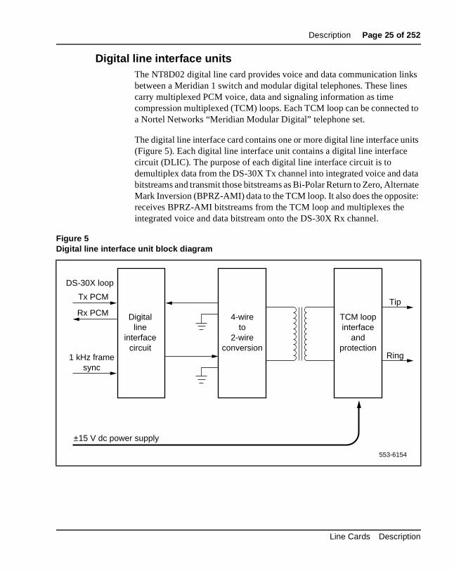
Digital line interface unitsThe NT8D02 digital line card provides voice and data communication linbetween a Meridian 1 switch and modular digital telephones. These linecarry multiplexed PCM voice, data and signaling information as time compression multiplexed (TCM) loops. Each TCM loop can be connectea Nortel Networks “Meridian Modular Digital” telephone set.
The digital line interface card contains one or more digital line interface un(Figure 5). Each digital line interface unit contains a digital line interface circuit (DLIC). The purpose of each digital line interface circuit is to demultiplex data from the DS-30X Tx channel into integrated voice and dbitstreams and transmit those bitstreams as Bi-Polar Return to Zero, AlterMark Inversion (BPRZ-AMI) data to the TCM loop. It also does the opposireceives BPRZ-AMI bitstreams from the TCM loop and multiplexes the integrated voice and data bitstream onto the DS-30X Rx channel.
Figure 5Digital line interface unit block diagram
4-wireto
2-wireconversion
Digitalline
interfacecircuit
TCM loopinterface
andprotection
Tip
Ring
DS-30X loop
Tx PCM
1 kHz framesync
Rx PCM
553-6154
±15 V dc power supply
Line Cards Description
Page 26 of 252 Description
ds le
uit.
op
ss
.
hat ith lls. and
The 4-wire to 2-wire conversion circuit converts the 2-wire tip and ring leainto a 4-wire (Tx and ground and RX and ground) signal that is compatibwith the digital line interface circuit.
TCM loop interfacesEach digital phone line terminates on the digital line card at a TCM loopinterface circuit. The circuit provides transformer coupling and foreign voltage protection between the TCM loop and the digital line interface circIt also provides power for the digital telephone set.
To prevent undesirable side effects from occurring when the TCM loop interface cannot provide the proper signals on the digital phone line, thesystem controller can remove the ±15 V dc power supply from the TCM lointerface. This happens when either the card gets a command from the NT8D01 Controller Card to shut down the channel or the digital line carddetects a loss of the 1 KHz frame synchronization signal.
Each TCM loop interface circuit can service loops up to 3500 ft. in lengthwhen using 24 gauge wire. The circuit allows for a maximum AC signal loof 15.5 dB at 256 KHz and a maximum DC loop resistance of 210 ohms
SignalingThe digital line interface units also contain signaling and control circuits testablish, monitor, and take down call connections. These circuits work wthe system controller to operate the digital line interface circuits during caThe circuits receive outgoing call signaling messages from the controller return incoming call status information to the controller over the DS-30Xnetwork loop.
553-3001-105 Standard 6.00 April 2000
Description Page 27 of 252
face are
es a ing
evice ook e
n X),
ing DC ) and
d tip rd
s
s).
ply. ves
that the lar
Analog line call operationThe applications, features, and signalling arrangements for each line interunit are configured in software and implemented on the card through softwdownload messages. When an analog line interface unit is idle, it providvoltage near ground on the tip lead and a voltage near –48 V dc on the rlead to the near-end station. (The near-end station is the telephone or dthat is connected to the analog line card by the tip and ring leads.) An on-htelephone presents a high impedance toward the line interface unit on thcard.
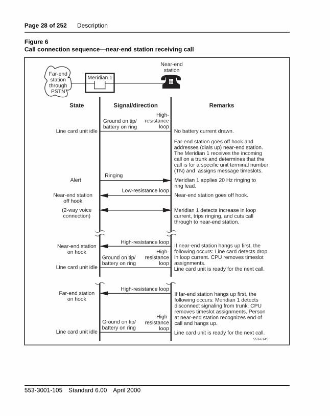
Incoming callsIncoming calls to a telephone that is connected to an analog line card caoriginate either from stations that are local (served by the Meridian 1 PBor remote (served through the public switched telephone network). The alerting signal to a telephone is 20 Hz (nominal) ringing. When an incomcall is answered by the near-end station going off-hook, a low-resistanceloop is placed across the tip and ring leads (towards the analog line cardringing is tripped (see Figure 6).
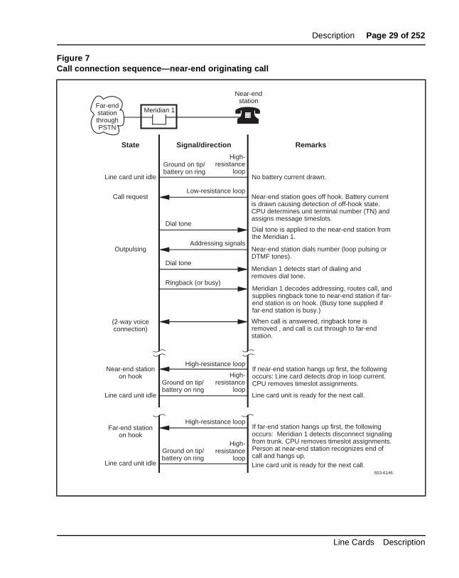
Outgoing callsFor outgoing calls from the near-end station, a line interface unit is seizewhen the station goes off-hook, placing a low-resistance loop across theand ring leads towards the analog line card (see Figure 7). When the cadetects the low-resistance loop, it prepares to receive digits. When the Meridian 1 is ready to receive digits, it returns dial tone. Outward addressignaling is then applied from the near-end station in the form of loop (interrupting) dial pulses or DTMF tones.
Message waitingLine cards that are equipped with the message waiting feature receive notification that a message is waiting across the Card LAN link (IPE cardOn cards that drive a message waiting light, the light is turned on by connecting the ring side of the telephone line to the –150 V dc power supWhen the line card senses that the telephone has gone off-hook, it remothe –150 V dc voltage until the telephone goes back on-hook. Line cardsuse an interrupted dial tone to indicate message waiting do nothing untilreceiver is picked up. The line card then interrupts the dial tone at a reguinterval to indicate that a message is waiting.
Line Cards Description
Page 28 of 252 Description
Figure 6Call connection sequence—near-end station receiving call
553-6145
High-resistance
loopLine card unit idle
(2-way voiceconnection)
Remarks
Ground on tip/battery on ring
Signal/directionState
Meridian 1
Ground on tip/ battery on ring
High-resistance loop
Ground on tip/ battery on ring
Far-end station on hook
Near-end station on hook
If near-end station hangs up first, the following occurs: Line card detects drop in loop current. CPU removes timeslot assignments.
If far-end station hangs up first, the following occurs: Meridian 1 detects disconnect signaling from trunk. CPU removes timeslot assignments. Person at near-end station recognizes end of call and hangs up.
No battery current drawn.
Far-end station goes off hook and addresses (dials up) near-end station. The Meridian 1 receives the incoming call on a trunk and determines that the call is for a specific unit terminal number (TN) and assigns message timeslots.
Meridian 1 applies 20 Hz ringing to ring lead.
Ringing
Low-resistance loopNear-end station
off hookNear-end station goes off hook.
Near-end station
Meridian 1 detects increase in loop current, trips ringing, and cuts call through to near-end station.
Line card unit is ready for the next call.
High-resistance
loop
Line card unit is ready for the next call.
High-resistance
loop
Line card unit idle
Line card unit idle
High-resistance loop
Far-end station through PSTN
Alert
553-3001-105 Standard 6.00 April 2000
Description Page 29 of 252
Figure 7Call connection sequence—near-end originating call
553-6146
High-resistance
loopLine card unit idle
(2-way voiceconnection)
Remarks
Ground on tip/battery on ring
Signal/directionState
Meridian 1
Ground on tip/ battery on ring
High-resistance loop
Ground on tip/ battery on ring
Far-end station on hook
Near-end station on hook
If near-end station hangs up first, the following occurs: Line card detects drop in loop current. CPU removes timeslot assignments.
If far-end station hangs up first, the following occurs: Meridian 1 detects disconnect signaling from trunk. CPU removes timeslot assignments. Person at near-end station recognizes end of call and hangs up.
No battery current drawn.
Near-end station goes off hook. Battery current is drawn causing detection of off-hook state. CPU determines unit terminal number (TN) and assigns message timeslots.
Low-resistance loop
Dial tone is applied to the near-end station from the Meridian 1.
Call request
Dial tone
Addressing signalsOutpulsing Near-end station dials number (loop pulsing or
DTMF tones).
Near-end station
Dial toneMeridian 1 detects start of dialing and removes dial tone.
Ringback (or busy)Meridian 1 decodes addressing, routes call, and supplies ringback tone to near-end station if far-end station is on hook. (Busy tone supplied if far-end station is busy.)
When call is answered, ringback tone is removed , and call is cut through to far-end station.
Line card unit is ready for the next call.
High-resistance
loop
Line card unit is ready for the next call.
High-resistance
loop
Line card unit idle
Line card unit idle
High-resistance loop
Far-end station through PSTN
Line Cards Description
Page 30 of 252 Description
cel
Card
ion n es
that
vice. tion
rd e ed.
that l state
he the m
In both cases, the message waiting indication will continue until the userchecks his or her messages. At that time, the Meridian 1 system will canthe message waiting indication by sending another message across theLAN link or Meridian 1 network loop.
Analog line supervisionAnalog line supervision features are used to extend the answer supervisand disconnect supervision signals when the line card is connected to aintelligent terminal device (Key system or intelligent pay phone). Two typof analog line supervision are provided, battery reversal answer and disconnect supervision, and hook flash disconnect supervision.
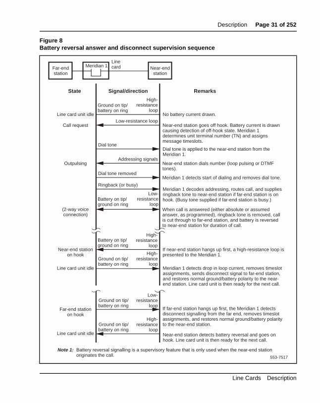
Battery reversal answer and disconnect supervisionBattery reversal answer and disconnect supervision is only used for callsoriginate from the terminal device. It provides both far-end answer supervision and far-end disconnect supervision signals to the terminal deIn an intelligent pay phone application, these signals provide the informanecessary to accurately compute toll charges.
In the idle state, and during dialing and ringing at the far end, the line caprovides a ground signal on the tip lead and battery on the ring lead (seFigure 8). When the far-end answers, these polarities are reversed. Thereversed battery connection is maintained as long as the call is establishWhen the far-end disconnects, the Meridian 1 system sends a messagecauses the line card to revert the battery and ground signals to the normato signal that the call is complete.
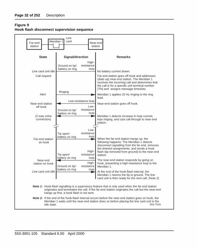
Hook Flash disconnect supervisionHook flash disconnect supervision is only used for incoming calls that terminate at the terminal device (typically a Key system), see Figure 9. Tdisconnect signal is indicated by the removal of the ground connection totip lead for a specific period of time. The period of time is programmableusing LD10, and ranges from a minimum of 10 milliseconds to a maximuof 2.55 seconds. See the X11 Administration (553-3001-311) for more information.
553-3001-105 Standard 6.00 April 2000
Description Page 31 of 252
Figure 8Battery reversal answer and disconnect supervision sequence
Meridian 1
High-resistance
loopLine card unit idle
(2-way voiceconnection)
Remarks
Ground on tip/battery on ring
Signal/directionState
Ground on tip/ battery on ring
High-resistance
loop
Ground on tip/ battery on ring
Far-end station on hook
Near-end station on hook
If near-end station hangs up first, a high-resistance loop is presented to the Meridian 1.
If far-end station hangs up first, the Meridian 1 detects disconnect signalling from the far end, removes timeslot assignments, and restores normal ground/battery polarity to the near-end station.
No battery current drawn.
Near-end station goes off hook. Battery current is drawn causing detection of off-hook state. Meridian 1 determines unit terminal number (TN) and assigns message timeslots.
Low-resistance loop
Dial tone is applied to the near-end station from the Meridian 1.
Call request
Dial tone
Addressing signalsOutpulsing Near-end station dials number (loop pulsing or DTMF
tones).Dial tone removed
Meridian 1 detects start of dialing and removes dial tone.
Ringback (or busy)Meridian 1 decodes addressing, routes call, and supplies ringback tone to near-end station if far-end station is on hook. (Busy tone supplied if far-end station is busy.)
When call is answered (either absolute or assumed answer, as programmed), ringback tone is removed, call is cut through to far-end station, and battery is reversed to near-end station for duration of call.
Meridian 1 detects drop in loop current, removes timeslot assignments, sends disconnect signal to far-end station, and restores normal ground/battery polarity to the near-end station. Line card unit is then ready for the next call.
High-resistance
loop
Near-end station detects battery reversal and goes on hook. Line card unit is then ready for the next call.
High-resistance
loop
Line card unit idle
Line card unit idle
Low-resistance
loop
Line card Near-end
stationFar-end station
Battery on tip/ ground on ring
Low-resistance
loop
Battery on tip/ ground on ring
Ground on tip/ battery on ring
Note 1: Battery reversal signalling is a supervisory feature that is only used when the near-end station originates the call. 553-7517
Line Cards Description
Page 32 of 252 Description
Figure 9Hook flash disconnect supervision sequence
High-resistance
loopLine card unit idle
(2-way voiceconnection)
Remarks
Ground on tip/battery on ring
Signal/directionState
Meridian 1
No battery current drawn.
Far-end station goes off hook and addresses (dials up) near-end station. The Meridian 1 receives the incoming call and determines that the call is for a specific unit terminal number (TN) and assigns message timeslots.
Meridian 1 applies 20 Hz ringing to the ring lead.
Ringing
Low-resistance loopNear-end station
off hookNear-end station goes off hook.
Meridian 1 detects increase in loop current, trips ringing, and cuts call through to near-end station.
Alert
Call request
Line card
Low-resistance
loopFar-end station
on hookWhen the far-end station hangs up, the following happens: The Meridian 1 detects disconnect signalling from the far end, removes the timeslot assignments, and sends a hook flash (tip removed from ground) to the near-end station.
Near-end station on hook
Tip open/ battery on ring
Tip open/ battery on ring
The near-end station responds by going on hook, presenting a high-resistance loop to the Meridian 1.
High-resistance
loop
Line card unit idle
Ground on tip/ battery on ring
At the end of the hook-flash interval, the Meridian 1 returns the tip to ground. The line card unit is then ready for the next call. (Note 2)
High-resistance
loop
Note 1: Hook-flash signalling is a supervisory feature that is only used when the far-end station originates and terminates the call. If the far-end station originates the call but the near-end hangs up first, a hook flash is not sent.
Note 2: If the end of the hook-flash interval occurs before the near-end station goes on hook, the Meridian 1 waits until the near-end station does so before placing the line card unit in the idle state. 553-7516
Near-end station
Far-end station
Ground on tip/battery on ring
Low-resistance
loop
553-3001-105 Standard 6.00 April 2000
Description Page 33 of 252
en e nce
on
on
s 24
ard s alog nit is the g its ted ead re
Digital line call operationDigital line call operation is controlled entirely by use of messages betwethe digital telephone set and the Meridian 1 system. These messages arcarried across the TCM loop interface. There is no call connection sequesimilar to the one used for analog telephone line operation.
Line-side T1 call operationThe line-side T1 card’s call operation is performed differently dependingwhether the T1 link is configured to process calls in loop start mode or ground start mode. Configuration is performed through dip switch settings the line-side T1 card.
The line-side T1 card performs calls processing separately on each of itchannels. Signaling is performed using the “A/B robbed bit” signaling standard for T1 communication. A/B robbed bit signaling simulates standanalog signaling by sending a meaningful combination of ones and zeroacross the line that correlates to the electrical impulses that standard ansignaling sends. For example, to represent that an analog line interface uidle, the analog line card provides a ground on the tip lead and -48Vdc onring lead. The line-side T1 card accomplishes the same result by sendinA bit as 0 (translated as ground on the tip lead) and its B bit as 1 (translaas -48Vdc on the ring lead). However, measuring the voltage of the ring lon the T1 line would not return -48Vdc, since actual electrical impulses anot being sent.
Call operation will be described by categorizing the operation into the following main states:
• Idle (on-hook)
• Incoming calls
• Outgoing calls
• Calls disconnected by the Central Office (CO)
• Calls disconnected by the telephone
Line Cards Description
Page 34 of 252 Description
e tip el 1 eive
n X),
an the an ,
hen e tip eive 1 to al at
Loop Start ModeIn Loop Start mode , the A and B bits have the following meaning:
Transmit from LTI:A bit = 0 (tip ground on)B bit = Ringing (0=on, 1=off)
Receive to LTI: A bit = Loop (0=open, 1=closed)B bit = 1 (no ring ground)
When a T1 channel is idle, the line-side T1 card simulates a ground on thlead and -48Vdc on the ring lead to the terminal equipment by setting itstransmit A bit to 0 and transmit B bit to 1. Accordingly, an on-hook channon the terminal equipment simulates an open loop toward the line-side Tcard, causing the line-side T1 card’s receive bits to be set to A = 0 and recB = 1.
Incoming callsIncoming calls to terminal equipment attached to the line-side T1 card caoriginate either from stations that are local (served by the Meridian 1 PBor remote (served through the public switched telephone network). To provide the ringing signal to a telephone the line-side T1 card simulatesadditional 90V on the ring lead to the terminal equipment by alternating transmit B bit between 0 and 1 (0 during ring on, 1 during ring off). Whenincoming call is answered by the terminal equipment going off-hook, theterminal equipment simulates tripping the ringing and shutting off ringingcausing the line-side T1 card’s receive A bit to be changed from 0 to 1.
Outgoing callsDuring outgoing calls from the terminal equipment, a channel is seized wthe station goes off-hook. This simulates a low-resistance loop across thand ring leads toward the line-side T1 card, causing the line-side T1’s recA bit to be changed from 0 to 1. This bit change prepares the line-side Treceive digits. Outward address signaling is then applied from the terminequipment in the form of DTMF tones or loop (interrupting) dial pulses thare signaled by the receive A bit pulsing between 1 and 0.
553-3001-105 Standard 6.00 April 2000
Description Page 35 of 252
the ed
end then the
ect, n )
ode,
ch
op
e de
ed
st
ook
Call disconnect from far end (PSTN, private network or local Station)When a call is in process, the central office may disconnect the call fromMeridian 1. If the line-side T1 port has been configured with the supervisanalog line (SAL) feature, the line-side T1 card will respond to the distant disconnect message by momentarily changing its transmit A bit to 1 and returning it to 0. The duration of time that the transmit A bit remains at 1before returning to 0 depends upon the setting that was configured usingSAL. If the terminal equipment is capable of detecting distant end disconnit will respond by changing the line-side T1 card's receive A bit to 0 (opeloop).The call is now terminated and the interface is in the idle (on-hookstate.
For the line-side T1 card to support distant end disconnect in loop start mthe following configuration parameters must exist:
• The Supervised Analog Line (SAL) feature must be configured for ealine-side T1 port.
Note: By default, the SAL feature opens the tip side for 750 m/s in lostart operation. This is configurable in 10 m/s increments.
• For outgoing trunk calls, the trunk facility must provide far end disconnect supervision.
• In order to detect distant end disconnect for calls originating on the line-side T1 card, the battery reversal feature within the SAL softwarmust be enabled. Enabling the battery reversal feature will not provibattery reversal indication but will only provide a momentary interruption of the tip ground by asserting the A bit to 1 for the specifiduration.
• In order to detect distant end disconnect for calls terminating on theline-side T1 card, the hook flash feature within the SAL software mube enabled.
• In order to detect distant end disconnect for calls originating and terminating on the line-side T1 card, both the battery reversal and hflash features must be enabled within the SAL software.
Line Cards Description
Page 36 of 252 Description
rent to
all
e tip e ne e T1
1 an 1 . To bit tip (by s
is nt
Call disconnect from line-side T1 terminal equipmentAlternatively, while a call is in process, the terminal equipment may disconnect by going on-hook. The terminal equipment detects no loop curand sends signaling to the line-side T1card that causes its receive A bit change from 1 to 0. The call is now released.
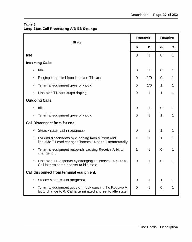
Table 3 outlines the line-side T1’s A and B bit settings in each state of cprocessing.
Ground Start ModeIn ground start mode, the A and B bits have the following meaning:
Transmit from LTI:A bit = Tip ground (0=grounded, 1=not grounded)B bit = Ringing (0=on, 1=off)
Receive to LTI: A bit = Loop (0=open, 1=closed)B bit = Ring ground (0=grounded, 1=not grounded)
When a T1 channel is idle, the line-side T1 card simulates a ground on thlead and -48Vdc on the ring lead to the terminal equipment by setting thtransmit A bit to 1 and transmit B bit to 1. Accordingly, an on-hook telephosimulates an open loop toward the line-side T1 card, causing the line-sidcard’s receive bits to be set to A = 0 and B = 1.
Incoming CallsIncoming calls to terminal equipment that is connected to the line-side Tcard can originate either from stations that are local (served by the MeridiPBX), or remote (served through the public switched telephone network)provide the ringing signal to the terminal equipment the line-side T1 cardsimulates the 90V ring signal on the ring lead by alternating the transmit Bbetween 0 and 1 (0 during ring on, 1 during ring off), and ground on the lead by setting the transmit A bit to 0. When an incoming call is answeredthe terminal equipment going off-hook), the terminal equipment simulatetripping the ringing and shutting off ringing by causing the line-side T1’s receive A bit to change from 0 to 1. The line-side T1 card responds to thmessage by simulating loop closure by holding the transmit B bit constaat 1.
553-3001-105 Standard 6.00 April 2000
Description Page 37 of 252
Table 3Loop Start Call Processing A/B Bit Settings
StateTransmit Receive
A B A B
Idle 0 1 0 1
Incoming Calls:
• Idle 0 1 0 1
• Ringing is applied from line-side T1 card 0 1/0 0 1
• Terminal equipment goes off-hook 0 1/0 1 1
• Line-side T1 card stops ringing 0 1 1 1
Outgoing Calls:
• Idle 0 1 0 1
• Terminal equipment goes off-hook 0 1 1 1
Call Disconnect from far end:
• Steady state (call in progress) 0 1 1 1
• Far end disconnects by dropping loop current and line-side T1 card changes Transmit A bit to 1 momentarily.
1 1 1 1
• Terminal equipment responds causing Receive A bit to change to 0.
1 1 0 1
• Line-side T1 responds by changing its Transmit A bit to 0. Call is terminated and set to idle state.
0 1 0 1
Call disconnect from terminal equipment:
• Steady state (call in progress) 0 1 1 1
• Terminal equipment goes on-hook causing the Receive A bit to change to 0. Call is terminated and set to idle state.
0 1 0 1
Line Cards Description
Page 38 of 252 Description
hen ad
tip s to
side
ide re,
smit it it to idle
rt
ch
op
re ide e
Outgoing CallsDuring outgoing calls from the terminal equipment, a channel is seized wthe terminal equipment goes off-hook, simulating a ground to the ring letoward the line-side T1 card by causing the line-side T1’s receive B bit tochange from 1 to 0. In turn, the line-side T1 card simulates grounding itslead by changing the transmit A bit to 0. The terminal equipment respondthis message by removing the ring ground (line-side T1’s receive B bit ischanged to 1) and simulating open loop at the terminal equipment (line-T1’s receive A bit is changed to 0).
Call disconnect from far end (PSTN, private network or local stationWhile a call is in process, the far end may disconnect the call. If the line-sT1 port has been configured with the supervised analog line (SAL) featuthe line-side T1 will respond to the distant end disconnect message by opening tip ground. This causes the line-side T1 card to change the tranA bit to 1. When the terminal equipment sees the transmit A bit go to 1, responds by simulating open loop causing the line-side T1’s receive A bchange to 0. The call is terminated and the interface is once again in thecondition.
For the line-side T1 card to support distant end disconnect in ground stamode, the following configuration parameters must exist:
• The Supervised Analog Line (SAL) feature must be configured for ealine-side T1 port.
Note: By default, the SAL feature opens the tip side for 750 m/s in lostart operation. This is configurable in 10 m/s increments.
• In order to detect distant end disconnect for calls originating on the line-side T1 card, the “battery reversal” feature within the SAL softwamust be enabled. Enabling the “battery reversal” feature will not provbattery reversal indication when a call is answered; it will only providbattery reversal indication when a call is disconnected.
553-3001-105 Standard 6.00 April 2000
Description Page 39 of 252
st
g the l is
all
ions e T1 of the tart
n 1 er
t end.
T1
• In order to detect distant end disconnect for calls terminating on theline-side T1 card, the “hook flash” feature within the SAL software mube enabled.
• In order to detect distant end disconnect for calls originating and terminating on the line-side T1 card, both the “battery reversal” and “hook flash” features within the SAL software must be enabled.
Call disconnect from line-side T1 terminal equipmentAlternatively, while a call is in process, the terminal equipment may disconnect by going on-hook, causing the line-side T1’s receive A bit to change to 0. The line-side T1 card responds to this message by simulatinremoval of ground from the tip by changing its transmit A bit to 1. The calnow terminated and the interface is once again in the idle condition.
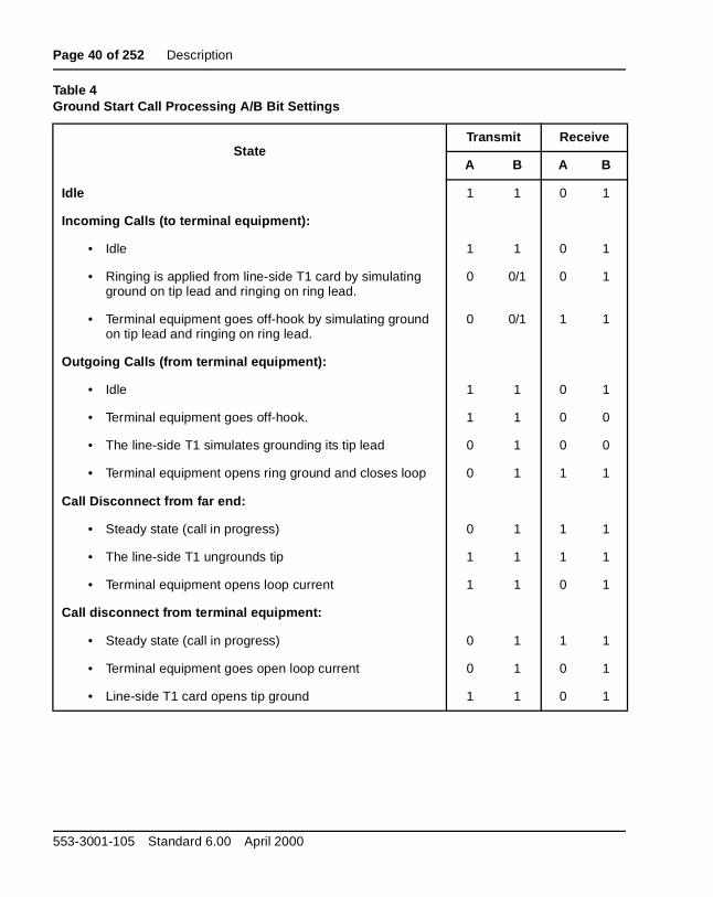
Table 4 outlines the line-side T1’s A and B bit settings in each state of cprocessing.
Ground Start RestrictionsIf you are using the line-side T1 card in ground start mode, certain restrictshould be considered. Because the Meridian 1 system treats the line-sidcard as a standard loop start analog line card, the ground start operation line-side T1 card has operational limitations compared to typical ground sinterface equipment relating to start of dialing, distant end disconnect and glare potential.
Distant end disconnect restrictionsIf the supervised analog line (SAL) feature is not available in your Meridiasoftware, the line-side T1 card is not capable of indicating to the CustomPremise Equipment (CPE) when a call has been terminated by the distanIn this case, the line-side T1 card will continue to provide a grounded tipindication (A=0) to the CPE until it detects an open loop indication (A=0)from the CPE, at which time it will provide an open tip indication (A=1). Therefore, without SAL software, the line-side T1 card is not capable of initiating the termination of a call to the CPE.
With the SAL software configured for each line-side T1 line, the line-side card will provide an open tip indication to the CPE when it receives an indication of supervised analog line from the Meridian 1 system, thus providing normal ground start protocol call termination.
Line Cards Description
Page 40 of 252 Description
Table 4Ground Start Call Processing A/B Bit Settings
StateTransmit Receive
A B A B
Idle 1 1 0 1
Incoming Calls (to terminal equipment):
• Idle 1 1 0 1
• Ringing is applied from line-side T1 card by simulating ground on tip lead and ringing on ring lead.
0 0/1 0 1
• Terminal equipment goes off-hook by simulating ground on tip lead and ringing on ring lead.
0 0/1 1 1
Outgoing Calls (from terminal equipment):
• Idle 1 1 0 1
• Terminal equipment goes off-hook. 1 1 0 0
• The line-side T1 simulates grounding its tip lead 0 1 0 0
• Terminal equipment opens ring ground and closes loop 0 1 1 1
Call Disconnect from far end:
• Steady state (call in progress) 0 1 1 1
• The line-side T1 ungrounds tip 1 1 1 1
• Terminal equipment opens loop current 1 1 0 1
Call disconnect from terminal equipment:
• Steady state (call in progress) 0 1 1 1
• Terminal equipment goes open loop current 0 1 0 1
• Line-side T1 card opens tip ground 1 1 0 1
553-3001-105 Standard 6.00 April 2000
Description Page 41 of 252
e far
on tor t the
ing to be
PE th
em
ll
e in
lines ly
ed
Glare restrictionsIn telephone lines or trunks, glare occurs when a call origination attemptresults in the answering of a terminating call that is being presented by thend simultaneously with the call origination attempt by the near end.
The line-side T1 detects presentation of a terminating call (outgoing to line-side T1 terminal equipment) by detecting ringing voltage. If applicatiof the ringing voltage is delayed due to traffic volume and ringing generacapacity overload, the line-side T1 ground start operation cannot connectip side to ground to indicate the line has been seized by the Meridian 1.
In ground start mode, glare conditions need to be considered if both incomand outgoing calls to the Customer Premise Equipment (CPE) are going encountered. In the event that both the Meridian 1 and the CPE simultaneously attempt to use a line-side T1 line, the Meridian 1 will complete the call termination rather than backing down and allowing the Cto complete the call origination, as in normal ground start operation. If boincoming and outgoing calls are to be handled through the line-side T1 interface, separate channels should be configured in the Meridian 1 systand the CPE for each call direction, to eliminate the possibility of glare conditions on call origination.
Voice frequency audio levelThe digital pad for line-side T1 card audio level is fixed for all types of caconnection (0 dB insertion loss in both directions), and differs from the Meridian 1 analog line. Audio level adjustments, if required, must be madthe line-side T1 terminal equipment.
Off-premise line protectionOff-premise applications are installations where the telephone lines are extended outside the building where the PBX system is housed, but the are not connected to public access facilities. This application is commonreferred to as a “campus installation.”
In off-premise applications, special protection devices and grounding arerequired to protect PBX and telephone components from any abnormal conditions that might occur. Abnormal conditions include, but are not limitto, lightning strikes and power line crosses.
Line Cards Description
Page 42 of 252 Description
st ards n
on, l
CC
g. ents
es hown of
rers as
ent. is
that
g ould
The NT1R20 Off-Premise Station Line Card has built-in protection againlightning strikes and power line crosses. These should be the preferred cfor an off-premise application. Some of the other cards can be used wheexternal line protectors are installed.
When using the line-side T1 card for an off-premise or network applicatiexternal line protectors must be installed. Install an isolated type channeservice unit (CSU) as part of your terminal equipment to provide the necessary isolation and outside line protection. The CSU should be an Fpart 68 or CSA certified unit.
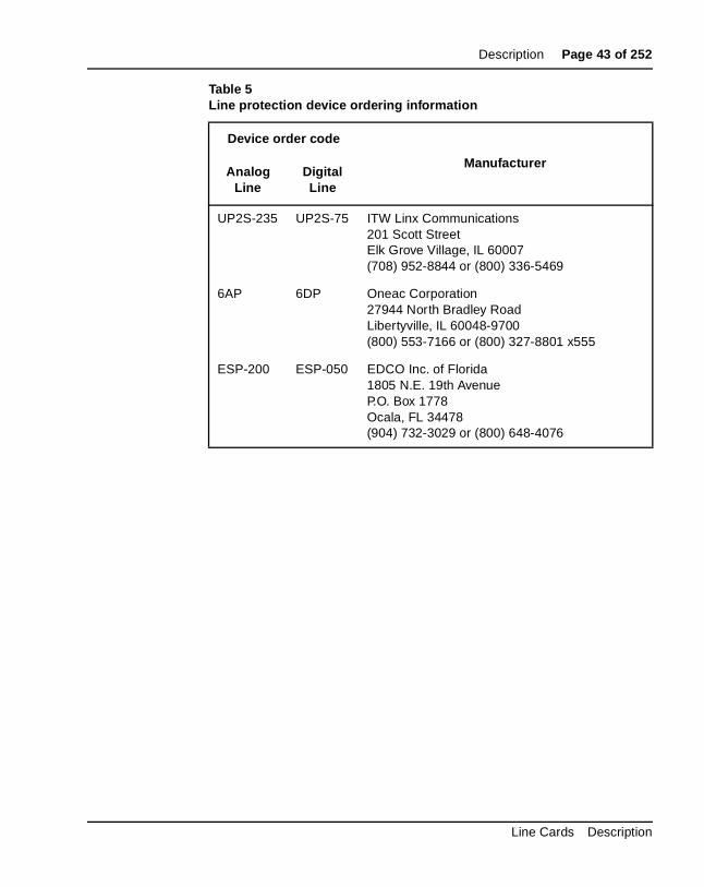
Line protectorsLine protectors are voltage-absorbing devices that are installed at the cross-connect terminals at both the main building and the remote buildinThe use of line protectors will ensure that system and telephone componare not damaged from accidental voltages that are within the limit of thecapacity of the protection device. Absolute protection from lightning strikand other stray voltages cannot be guaranteed, but proven cases have sthat the use of line protection devices significantly reduces the possibilitydamage.
Nortel Networks has tested line protection devices from three manufactu(see Table 5). Each manufacturer offers devices for protection of digital well as analog telephone lines.
These devices are compatible with 66 type M1-50 split blocks or equivalConsult the device manufacturer if more specific compatibility informationrequired.
Line protection groundingIn conjunction with line protectors, proper system (PBX) grounding is essential to minimize equipment damage. Nortel Networks recommendsyou follow the grounding connection requirements as described in System Installation Procedures (553-3001-210). This requirement includes connecting the ground for the protection devices to the approved buildinearth ground reference. Any variances to these grounding requirements climit the functionality of the protection device.
553-3001-105 Standard 6.00 April 2000
Description Page 43 of 252
Table 5Line protection device ordering information
Device order code
ManufacturerAnalog
LineDigitalLine
UP2S-235 UP2S-75 ITW Linx Communications201 Scott StreetElk Grove Village, IL 60007(708) 952-8844 or (800) 336-5469
6AP 6DP Oneac Corporation27944 North Bradley RoadLibertyville, IL 60048-9700(800) 553-7166 or (800) 327-8801 x555
ESP-200 ESP-050 EDCO Inc. of Florida1805 N.E. 19th AvenueP.O. Box 1778Ocala, FL 34478(904) 732-3029 or (800) 648-4076
Line Cards Description
Page 44 of 252 Description
Line and telephone componentsBecause testing of the line protectors was limited to the line cards and telephones shown below, only these components should be used for off-premise installations.
Telephones
• Meridian Modular Telephones (digital)
• Meridian Digital Telephones
• Standard analog (500/2500) telephones
Line Cards
• NT1R20 Off-Premise Station Line Card
• NT8D02 Digital Line Card
• NT8D03 Analog Line Card
• NT8D09 Analog Line Card with Message Waiting
• NTRD24 24-port Digital Line Card
553-3001-105 Standard 6.00 April 2000
Page 45 of 252
66
NT1R20 Off-Premise Station Analog Line Card
Content listThe following are the topics in this section:
• Introduction 46
• Physical description 46
• Functional description 49
• Card interfaces 50
• Line interface units 50
• Card control functions 51
• Circuit power 52
• Electrical specifications 53
• Analog line interface 53
• Power requirements 54
• Foreign and surge voltage protection 54
• Ringer limitations 55
• Environmental specifications 55
• Connector pin assignments 56
• Configuring the OPS analog line card 58
• Jumper strap settings 58
• Software service changes 58
Line Cards Description
Page 46 of 252 NT1R20 Off-Premise Station Analog Line Card
nt 37
lines ach log
-pin l on me
ilar
• Port-to-port loss configuration 61
• Applications 62
• Off-premise station application 62
• Other applications 62
• Transmission considerations 64
Reference listThe following are the references in this section:
• Summary of Transmission Parameters (553-2201-182)
• System Installation Procedures (553-3001-210)
• X11 Administration (553-3001-311)
IntroductionThe NT1R20 Off-Premise Station (OPS) Analog Line Card is an intelligeperipheral equipment (IPE) device that can be installed in either the NT8DIPE Module. The OPS analog line card interfaces eight analog telephone with hazardous and surge voltage protection to the Meridian 1 switch. Eline interface is independently configurable by software control in the Ana(500/2500) Telephone Administration program (LD 10).
Physical descriptionThe OPS analog line card mounts in any IPE slot. The line interface andcommon multiplexing circuitry is mounted on a 31.75 cm by 25.40 cm (12.5 in. by 10 in.) printed circuit board.
The OPS analog line card connects to the IPE backplane through a 160connector shroud. The backplane is cabled to the input/output (I/O) panethe rear of the module, which is then connected to the main distribution fra(MDF) by 25-pair cables. Telephone lines from station equipment cross connect to the OPS analog line card at the MDF using a wiring plan simto that used for trunk cards. See System Installation Procedures (553-3001-210) for termination and cross-connect information.
553-3001-105 Standard 6.00 April 2000
NT1R20 Off-Premise Station Analog Line Card Page 47 of 252
) ains s
e ED
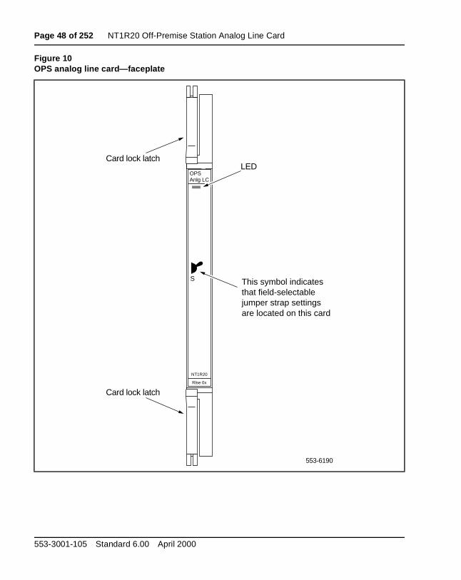
The faceplate of the card is equipped with a red light-emitting diode (LED(see Figure 10). When an OPS analog line card is installed, the LED remlit for two to five seconds while the self-test runs. If the self-test completesuccessfully, the LED flashes (off/on) three times and remains lit until thcard is configured and enabled in software; then the LED goes out. If the Ldoes not follow this pattern or operates in any other manner, such as continually flashing or remaining weakly lit, the card should be replaced.
Line Cards Description
Page 48 of 252 NT1R20 Off-Premise Station Analog Line Card
Figure 10OPS analog line card—faceplate
S
OPSAnlg LC
NT1R20
Rlse 0x
Card lock latch
Card lock latch
This symbol indicatesthat field-selectablejumper strap settingsare located on this card
LED
553-6190
553-3001-105 Standard 6.00 April 2000
NT1R20 Off-Premise Station Analog Line Card Page 49 of 252
e
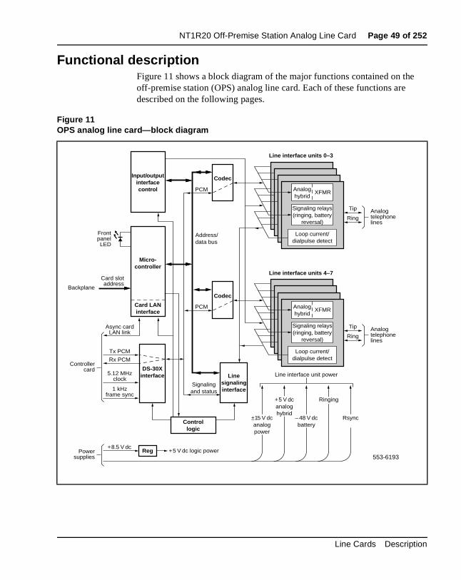
Functional descriptionFigure 11 shows a block diagram of the major functions contained on thoff-premise station (OPS) analog line card. Each of these functions are described on the following pages.
Figure 11OPS analog line card—block diagram
Input/outputinterfacecontrol
Codec
PCM
Micro-controller
DS-30Xinterface5.12 MHz
clock
Tx PCM
Async cardLAN link
FrontpanelLED
Card LANinterface
Tip
Line interface units 0–3
Ring
Codec
PCM Analoghybrid
XFMR
Signaling relays(ringing, battery
reversal)
Line interface units 4–7
Line interface unit power
Rx PCM
1 kHzframe sync
Controllercard
Linesignalinginterface
Controllogic
Reg
Signalingand status
Address/data bus
553-6193Power
supplies
+5 V dcanaloghybrid
±15 V dcanalogpower
+8.5 V dc+5 V dc logic power
Ringing
– 48 V dcbattery
Rsync
Analogtelephonelines
Tip
RingAnalogtelephonelines
Loop current/dialpulse detect
Analoghybrid
XFMR
Signaling relays(ringing, battery
reversal)
Loop current/dialpulse detect
Card slotaddress
Backplane
Line Cards Description
Page 50 of 252 NT1R20 Off-Premise Station Analog Line Card
oops ssed
o
ls. s for re
asis
sis
or
Card interfacesThe OPS analog line card passes voice and signaling data over DS-30X land maintenance data over the card LAN link. These interfaces are discuin detail in “Intelligent peripheral equipment line cards” on page 12.
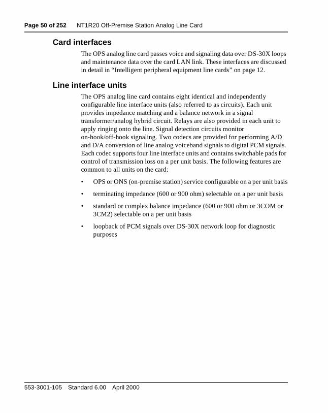
Line interface unitsThe OPS analog line card contains eight identical and independently configurable line interface units (also referred to as circuits). Each unit provides impedance matching and a balance network in a signal transformer/analog hybrid circuit. Relays are also provided in each unit tapply ringing onto the line. Signal detection circuits monitor on-hook/off-hook signaling. Two codecs are provided for performing A/Dand D/A conversion of line analog voiceband signals to digital PCM signaEach codec supports four line interface units and contains switchable padcontrol of transmission loss on a per unit basis. The following features acommon to all units on the card:
• OPS or ONS (on-premise station) service configurable on a per unit b
• terminating impedance (600 or 900 ohm) selectable on a per unit ba
• standard or complex balance impedance (600 or 900 ohm or 3COM3CM2) selectable on a per unit basis
• loopback of PCM signals over DS-30X network loop for diagnostic purposes
553-3001-105 Standard 6.00 April 2000
NT1R20 Off-Premise Station Analog Line Card Page 51 of 252
d
rnal he
Card control functionsControl functions are provided by a microcontroller, a Card LAN link, ansignaling and control circuits on the OPS analog line card.
MicrocontrollerThe OPS analog line card contains a microcontroller that controls the inteoperation of the card and the serial card LAN link to the controller card. Tmicrocontroller controls the following:
• reporting to the CE CP via the card LAN link:
— card identification (card type, vintage, and serial number)
— firmware version
— self-test status
— programmed configuration status
• receipt and implementation of card configuration:
— programming of the codecs
— enabling/disabling of individual units or entire card
— programming of input/output interface control circuits for administration of line interface unit operation
— enabling/disabling of an interrupted dial tone to indicate call waiting
— maintenance diagnostics
— transmission loss levels
Line Cards Description
Page 52 of 252 NT1R20 Off-Premise Station Analog Line Card
ard
dial led. s r of
ish, ng
ic he
e sets the of
Card LAN interfaceMaintenance data is exchanged with the Common Equipment CP over adedicated asynchronous serial network called the Card LAN link. The CLAN link is described in the section “Intelligent peripheral equipment” onpage 17.
The OPS analog line card has the capability of providing an interrupted tone to indicate that a message is waiting or that call forwarding is enabThe line card (optionally) receives messages stating that these conditionexist over the Card LAN Interface and interrupts the dial tone when eithethese conditions are detected.
Signaling and controlThe signaling and control portion of the card provides circuits that establsupervise, and take down call connections. These circuits work with thesystem CP to operate the line interface circuits during calls. The circuitsreceive outgoing call signaling messages from the CP and return incomicall status information over the DS-30X network loop.
Circuit powerThe +8.5 V dc input is regulated down to +5 V dc for use by the digital logcircuits. All other power to the card is used by the line interface circuits. T±15.0 V dc inputs to the card are used to power the analog circuits. The+5 V dc from the module power supply is used for the analog hybrid. Th–48.0 V dc input is for telephone set battery. Ringing power for telephone is 86 Vrms ac at 20 Hz on –48 V dc. The Rsync signal is used to switch 20 Hz ringing on and off at the zero cross-over point to lengthen the life the switching circuits.
553-3001-105 Standard 6.00 April 2000
NT1R20 Off-Premise Station Analog Line Card Page 53 of 252
d.
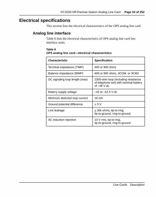
Electrical specificationsThis section lists the electrical characteristics of the OPS analog line car
Analog line interfaceTable 6 lists the electrical characteristics of OPS analog line card line interface units.
Table 6OPS analog line card—electrical characteristics
Characteristic Specification
Terminal impedance (TIMP) 600 or 900 ohms
Balance impedance (BIMP) 600 or 900 ohms, 3COM, or 3CM2
DC signaling loop length (max) 2300-ohm loop (including resistance of telephone set) with nominal battery of –48 V dc
Battery supply voltage –42 to –52.5 V dc
Minimum detected loop current 16 mA
Ground potential difference ± 3 V
Line leakage > 30k ohms, tip-to-ring, tip-to-ground, ring-to-ground
AC induction rejection 10 V rms, tip-to-ring, tip-to-ground, ring-to-ground
Line Cards Description
Page 54 of 252 NT1R20 Off-Premise Station Analog Line Card
stem
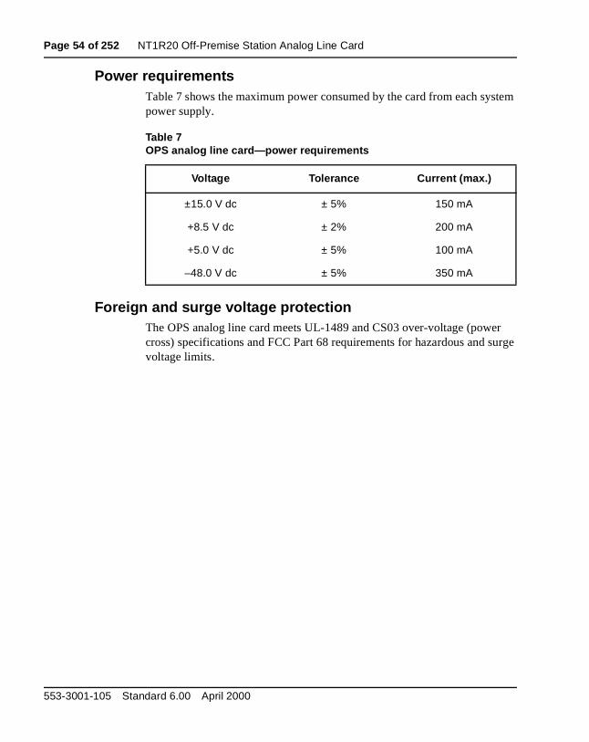
r urge
Power requirementsTable 7 shows the maximum power consumed by the card from each sypower supply.
Foreign and surge voltage protectionThe OPS analog line card meets UL-1489 and CS03 over-voltage (powecross) specifications and FCC Part 68 requirements for hazardous and svoltage limits.
Table 7OPS analog line card—power requirements
Voltage Tolerance Current (max.)
±15.0 V dc ± 5% 150 mA
+8.5 V dc ± 2% 200 mA
+5.0 V dc ± 5% 100 mA
–48.0 V dc ± 5% 350 mA
553-3001-105 Standard 6.00 April 2000
NT1R20 Off-Premise Station Analog Line Card Page 55 of 252
line
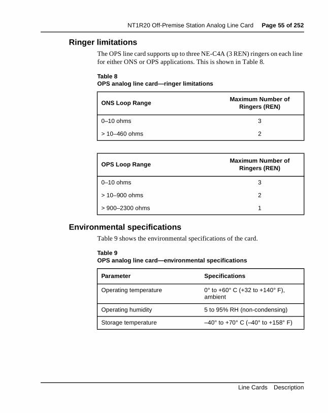
Ringer limitationsThe OPS line card supports up to three NE-C4A (3 REN) ringers on eachfor either ONS or OPS applications. This is shown in Table 8.
Environmental specificationsTable 9 shows the environmental specifications of the card.
Table 8OPS analog line card—ringer limitations
ONS Loop Range Maximum Number of
Ringers (REN)
0–10 ohms 3
> 10–460 ohms 2
OPS Loop RangeMaximum Number of
Ringers (REN)
0–10 ohms 3
> 10–900 ohms 2
> 900–2300 ohms 1
Table 9OPS analog line card—environmental specifications
Parameter Specifications
Operating temperature 0° to +60° C (+32 to +140° F), ambient
Operating humidity 5 to 95% RH (non-condensing)
Storage temperature –40° to +70° C (–40° to +158° F)
Line Cards Description
Page 56 of 252 NT1R20 Off-Premise Station Analog Line Card
o the d to
line A
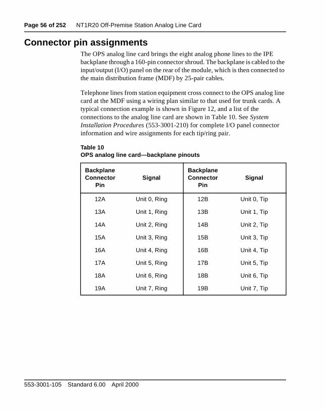
Connector pin assignmentsThe OPS analog line card brings the eight analog phone lines to the IPEbackplane through a 160-pin connector shroud. The backplane is cabled tinput/output (I/O) panel on the rear of the module, which is then connectethe main distribution frame (MDF) by 25-pair cables.
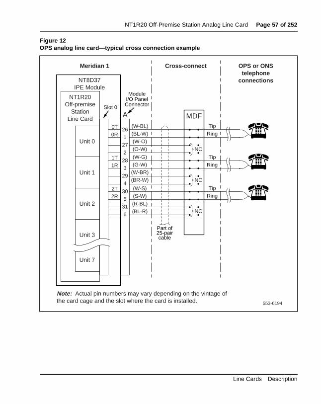
Telephone lines from station equipment cross connect to the OPS analogcard at the MDF using a wiring plan similar to that used for trunk cards. typical connection example is shown in Figure 12, and a list of the connections to the analog line card are shown in Table 10. See System Installation Procedures (553-3001-210) for complete I/O panel connector information and wire assignments for each tip/ring pair.
Table 10OPS analog line card—backplane pinouts
BackplaneConnector
PinSignal
BackplaneConnector
PinSignal
12A Unit 0, Ring 12B Unit 0, Tip
13A Unit 1, Ring 13B Unit 1, Tip
14A Unit 2, Ring 14B Unit 2, Tip
15A Unit 3, Ring 15B Unit 3, Tip
16A Unit 4, Ring 16B Unit 4, Tip
17A Unit 5, Ring 17B Unit 5, Tip
18A Unit 6, Ring 18B Unit 6, Tip
19A Unit 7, Ring 19B Unit 7, Tip
553-3001-105 Standard 6.00 April 2000
NT1R20 Off-Premise Station Analog Line Card Page 57 of 252
Figure 12OPS analog line card—typical cross connection example
553-6194
NT8D37IPE Module
Slot 0
NT1R20Off-premise
StationLine Card
Unit 0
Unit 7
0T
0R26
1
27
2
Meridian 1 Cross-connect OPS or ONStelephone
connections
A MDF
Unit 1
Unit 2
Unit 3
Tip
Ring
Tip
Ring28
3
29
42T
2R
1T
1R
30
5
31
6
Tip
Ring
NC
NC
NC
ModuleI/O PanelConnector
Part of25-paircable
Note: Actual pin numbers may vary depending on the vintage of the card cage and the slot where the card is installed.
(W-BL)
(BL-W)
(W-O)
(O-W)
(W-G)
(G-W)
(W-BR)
(BR-W)
(W-S)
(S-W)
(R-BL)
(BL-R)
Line Cards Description
Page 58 of 252 NT1R20 Off-Premise Station Analog Line Card
for he
hat ee
er
. To and es
to
lect and and
Configuring the OPS analog line cardThe line type, terminating impedance, and balance network configurationeach unit on the card is selected by software service change entries at tsystem terminal and by jumper strap settings on the card.
Jumper strap settingsEach line interface unit on the card is equipped with two jumper blocks tare used to select the proper loop current depending upon loop length (sTable 11). For units connected to loops of 460 to 2300 ohms, both jumpblocks for that unit must have jumper blocks installed. For loops that are460 ohms or less, jumper blocks are not installed. Figure 13 shows the location of the jumper blocks on the OPS analog line card.
Before the appropriate balance network can be selected, the loop lengthbetween the near-end (Meridian 1) and the far-end station must be knownassist in determining loop length, Table 12 shows some typical resistanceloss values for the most common cable lengths for comparison with valuobtained from actual measurements.
Software service changesIndividual line interface units on the OPS analog line card are configuredeither OPX (for OPS application) or ONP (for ONS application) class-of-service (CLS) using the Analog (500/2500) Telephone Administration program (LD 10). (See Table 11.) LD 10 is also used to seunit terminating impedance and balance network impedance at the TIMPBIMP prompts, respectively. The message waiting interrupted dial tone call forward reminder tone features are enabled by entering data into thecustomer data block using LD 15. See the X11 Administration (553-3001-311) for LD 10 and LD 15 service change instructions.
553-3001-105 Standard 6.00 April 2000
NT1R20 Off-Premise Station Analog Line Card Page 59 of 252
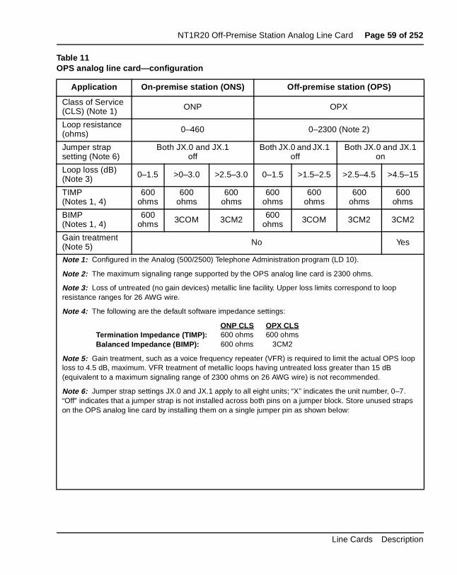
Table 11OPS analog line card—configuration
Application On-premise station (ONS) Off-premise station (OPS)
Class of Service (CLS) (Note 1) ONP OPX
Loop resistance (ohms) 0–460 0–2300 (Note 2)
Jumper strap setting (Note 6)
Both JX.0 and JX.1 off
Both JX.0 and JX.1 off
Both JX.0 and JX.1 on
Loop loss (dB) (Note 3) 0–1.5 >0–3.0 >2.5–3.0 0–1.5 >1.5–2.5 >2.5–4.5 >4.5–15
TIMP (Notes 1, 4)
600 ohms
600 ohms
600 ohms
600 ohms
600 ohms
600 ohms
600 ohms
BIMP (Notes 1, 4)
600 ohms 3COM 3CM2 600
ohms 3COM 3CM2 3CM2
Gain treatment (Note 5) No Yes
Note 1: Configured in the Analog (500/2500) Telephone Administration program (LD 10).
Note 2: The maximum signaling range supported by the OPS analog line card is 2300 ohms.
Note 3: Loss of untreated (no gain devices) metallic line facility. Upper loss limits correspond to loop resistance ranges for 26 AWG wire.
Note 4: The following are the default software impedance settings:
ONP CLS OPX CLSTermination Impedance (TIMP): 600 ohms 600 ohmsBalanced Impedance (BIMP): 600 ohms 3CM2
Note 5: Gain treatment, such as a voice frequency repeater (VFR) is required to limit the actual OPS loop loss to 4.5 dB, maximum. VFR treatment of metallic loops having untreated loss greater than 15 dB (equivalent to a maximum signaling range of 2300 ohms on 26 AWG wire) is not recommended.
Note 6: Jumper strap settings JX.0 and JX.1 apply to all eight units; “X” indicates the unit number, 0–7. “Off” indicates that a jumper strap is not installed across both pins on a jumper block. Store unused straps on the OPS analog line card by installing them on a single jumper pin as shown below:
Line Cards Description
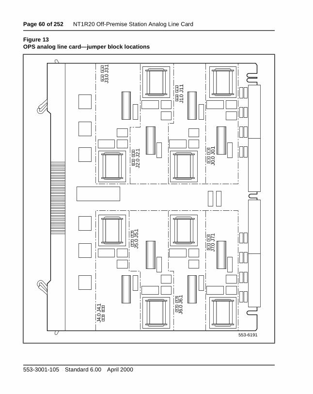
Page 60 of 252 NT1R20 Off-Premise Station Analog Line Card
Figure 13OPS analog line card—jumper block locations
553-6191
J4.0
J4.1
J6.0
J6.1
J7.0
J7.1
J0.0
J0.1
J2.0
J2.1
J3.0
J3.1
J1.0
J1.1
J5.0
J5.1
553-3001-105 Standard 6.00 April 2000
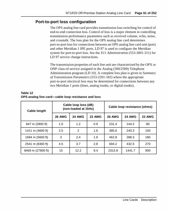
NT1R20 Off-Premise Station Analog Line Card Page 61 of 252
l of ling oise,
ort)
X or
ny
Port-to-port loss configurationThe OPS analog line card provides transmission loss switching for controend-to-end connection loss. Control of loss is a major element in controltransmission performance parameters such as received volume, echo, nand crosstalk. The loss plan for the OPS analog line card determines port-to-port loss for connections between an OPS analog line card unit (pand other Meridian 1 IPE ports. LD 97 is used to configure the Meridian system for port-to-port loss. See the X11 Administration (553-3001-311) for LD 97 service change instructions.
The transmission properties of each line unit are characterized by the OPONP class-of-service assigned in the Analog (500/2500) Telephone Administration program (LD 10). A complete loss plan is given in Summary of Transmission Parameters (553-2201-182) where the appropriate port-to-port electrical loss may be determined for connections between atwo Meridian 1 ports (lines, analog trunks, or digital trunks).
Table 12OPS analog line card—cable loop resistance and loss
Cable length
Cable loop loss (dB)(non-loaded at 1kHz)
Cable loop resistance (ohms)
26 AWG 24 AWG 22 AWG 26 AWG 24 AWG 22 AWG
847 m (2800 ft) 1.5 1.2 0.9 231.4 144.2 90
1411 m (4600 ft) 2.5 2 1.6 385.6 240.3 150
1694 m (5600 ft) 3 2.4 1.9 462.8 288.3 180
2541 m (8300 ft) 4.5 3.7 2.8 694.2 432.5 270
8469 m (27800 ft) 15 12.2 9.4 2313.9 1441.7 900
Line Cards Description
Page 62 of 252 NT1R20 Off-Premise Station Analog Line Card
n
al ; S
are the
n in
e
line
ch
ier ent.
e
ed
ApplicationsOff-premise station application
The NT1R20 Off-Premise Station (OPS) Analog Line Card is designed primarily to provide an interface for Meridian 1 off-premise station lines. AOPS line serves a terminal—typically, but not exclusively, a telephone set—remote from the PBX either within the same serving area as the locoffice or through a distant office. The line is not switched at these officeshowever, depending on the facilities used, the local office serving the OPstation may provide line functions such as battery and ringing. Facilities generally provided by the local exchange carrier (OPS pairs are usually insame cable as the PBX-CO trunks). The traditional OPS scenario configuration is shown in Figure 14.
Note: OPS service should not be confused with off-premise extensio(OPX) service. OPX service is the provision of an extension to a masubscriber loop bridged onto the loop at the serving CO or PBX. Additionally, OPX as used to denote off-premise extension service should not be confused with the OPX class-of-service assigned in thAnalog (500/2500) Telephone Administration program (LD 10).
Other applicationsThe operating range and built-in protection provisions of the OPS analogcard make it suitable for applications that are variants on the traditional configuration shown in Figure 14. The following are some examples of suapplications:
• a PBX in a central building serving stations in other buildings in the vicinity, such as in an industrial park (often called a campus environment). Facilities may be provided by the local exchange carror may be privately owned. Protection may or may not be a requirem
• termination to other than a telephone set, such as to a key telephonsystem
• individual circuits on the OPS analog line card may also be configuras ONS ports in LD 10:
— to have ONS service with hazardous and surge voltage protection (not available on other Meridian 1 analog line cards)
— to use otherwise idle OPS analog line card ports
553-3001-105 Standard 6.00 April 2000

NT1R20 Off-Premise Station Analog Line Card Page 63 of 252
Figure 14Traditional OPS application configuration
553-6147
Meridian 1PBX
PublicNetwork
Non-switchedthru connections
OPS analog line card port
CO trunk card port
OPS termination
LocalCO
DistantCO
0–3.5 dB 4.5 dB maximum
7.0 dB total maximum
OPS line facility
Line Cards Description
Page 64 of 252 NT1R20 Off-Premise Station Analog Line Card
g
and
PS
tion
OPS
14.
1 the
log r, sis
that
ld BX
n
Transmission considerationsThe transmission performance of OPS lines is dependent on the followinfactors:
• the Meridian 1 port-to-port loss for connections between OPS ports other Meridian 1 ports
• the transmission parameters of the facilities between the Meridian 1 Oport and the off-premise station or termination
• the electrical and acoustic transmission characteristics of the termina
These factors must be considered when planning applications using the analog line card. They are of particular importance when considering configurations other than the traditional OPS application shown in FigureThe discussion which follows is intended to provide basic transmission planning guidelines for various OPS applications.
Port-to-port lossLoss is inserted between OPS analog line card ports and other Meridianports in accordance with the Meridian 1 loss plan. This plan determines port-to-port loss for each call. When a port is configured for OPX class-of-service, loss is programmed into the OPS analog line card on acall-by-call basis. When configured for ONP class-of-service, an OPS analine card port is programmed to a value that is fixed for all calls. Howevethe loss in the other port involved in the call may vary on a call-by-call bato achieve the total loss scheduled by the plan. Summary of Transmission Parameters (553-2201-182) shows the specific loss for each possible port-to-port combination.
For satisfactory transmission performance, particularly on connections between the public network and an OPS termination, it is recommendedfacilities conform to the following:
• Total 1 kHz loss from the local serving CO to the OPS terminal shounot exceed 7.0 dB. Of that total, the loss in the facility between the Pand the terminal should not exceed 4.5 dB (see Figure 14).
The following requirements are based on historic inserted connectioloss (ICL) objectives:
553-3001-105 Standard 6.00 April 2000
NT1R20 Off-Premise Station Analog Line Card Page 65 of 252
to ns ell r
z.
dB, l
ling to n
ated of ing
og
• PBX–CO trunk: 5 dB with gain; 0–4.0 dB without gain
• OPS line: 4.0 dB with gain; 0–4.5 dB without gain
In recent times economic and technological considerations have ledmodifications of these historic objectives. However, the loss provisioin the PBX for OPS are constrained by regulatory requirements as was industry standards; thus, they are not designed to compensate fomodified ICL designs in the connecting facilities.
• The attenuation distortion (frequency response) of the OPS facility should be within ±3.0 dB over the frequency range from 300 to 3000 HIt is desirable that this bandwidth extend from 200 to 3200 Hz.
• The terminating impedance of the facility at the OPS port should approximate that of 600 ohm cable.
If the OPS line facility loss is greater than 4.5 dB but does not exceed 15line treatment using a switched-gain voice frequency repeater (VFR) wilextend the voice range.
The overall range achievable on an OPS line facility is limited by the signaling range (2300 ohm loop including telephone set resistance). Signarange is unaffected by gain treatment; thus, gain treatment can be usedextend the voice range to the limit of the signaling range. For example, o26AWG wire, the signaling range of 2300 ohms corresponds to an untremetallic loop loss of 15 dB. Gain treatment (such as a VFR) with 10.5 dBgain would maintain the OPS service loss objective of 4.5 dB while extendthe voice range to the full limit of the signaling range:
The use of dial long line units to extend the signaling range of OPS analline cards beyond 15 dB is not recommended.
15.0 dB (loss corresponding to the maximum signaling range)
– 4.5 dB (OPS service loss objective)
= 10.5 dB (required gain treatment)
Line Cards Description
Page 66 of 252 NT1R20 Off-Premise Station Analog Line Card
an en the istics, ation
is
ness
set from
g
ing
to n e ce.
Termination transmission characteristicsThe loss plan for OPS connections is designed so that a connection withOPS termination will provide satisfactory end-to-end listener volume whthe OPS termination is a standard telephone set. The listener volume atdistant end depends on the OPS termination transmit loudness characterand the volume at the OPS termination end depends on the OPS terminreceive loudness characteristics. With standard telephone sets, these characteristics are such that satisfactory—if not optimum—performanceachievable within the above noted objectives for connecting facilities.
A feature of many (though not all) standard telephone sets is that the loudincreases with decreased current. Thus, as the line (Meridian 1 to OPS termination) facility gets longer and lossier, the increased loudness of thesomewhat compensates for the higher loss, assuming direct current feedthe PBX with constant voltage at the feeding bridge. However, this compensation is not available when the following occurs:
• the termination is a non-compensating telephone set
• the OPS port is served by a line card using a constant-current feedinbridge
• the OPS termination is to telephone sets behind a local switch providlocal current feed, such as a key telephone system
OPS line terminations with loudness characteristics designed for other applications may also impact transmission performance. For example, wireless portables loudness characteristics are selected for connectionsswitching systems for wireless communication systems; if deployed in aOPS arrangement without due consideration for these characteristics, thresult could be a significant deviation from optimum loudness performan
553-3001-105 Standard 6.00 April 2000
Page 67 of 252
124
NT5D11 Line-side T1 Interface CardContent list
The following are the topics in this section:
• Introduction 68
• Physical description 69
• Card connections 69
• Faceplate 69
• Functional description 74
• Overview 75
• Card interfaces 76
• T1 interface circuit 76
• Signaling and control 76
• Card control functions 76
• Electrical specifications 79
• T1 channel specifications 79
• Power requirements 79
• Foreign and surge voltage protections 80
• Environmental specifications 80
• Installation and Configuration 81
• Dip switch settings 81
• Installation 88
Line Cards Description
Page 68 of 252 NT5D11 Line-side T1 Interface Card
ing lates nnel 0) es t
• Cabling the line-side T1 card 91
• Terminal configuration 99
• Software configuration 99
• Man-Machine T1 maintenance interface software 102
• Description 102
• Login and Password 104
• Basic commands 104
• Configuring parameters 107
• Alarm operation and reporting 112
• Performance counters and reporting 115
• Testing 117
• Applications 121
Reference listThe following reference is found in this section:
• System Installation Procedures (553-3001-210)
IntroductionThe NT5D11 Line-side T1 Interface Card is an intelligent peripheral equipment (IPE) line card that can be installed in either the NT8D37 IPEmodule (up to eight cards).
The line-side T1 card interfaces one T1 line, carrying 24 channels, to theMeridian 1 switch. This card occupies two card slots in the IPE shelf, utiliz16 channels on slot 1 and 8 channels on slot 2. The line-side T1 card emuan analog line card to the Meridian 1 system software; therefore, each chais independently configurable by software control in the Analog (500/250Telephone Administration program (LD10). The line-side T1 card also comequipped with a Man-Machine Interface (MMI) maintenance program thaprovides diagnostic information regarding the status of the T1 link.
553-3001-105 Standard 6.00 April 2000
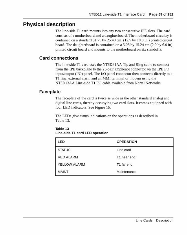
NT5D11 Line-side T1 Interface Card Page 69 of 252
rd try is cuit 0 in)
t O to a
and ith
Physical descriptionThe line-side T1 card mounts into any two consecutive IPE slots. The caconsists of a motherboard and a daughterboard. The motherboard circuicontained on a standard 31.75 by 25.40 cm. (12.5 by 10.0 in.) printed cirboard. The daughterboard is contained on a 5.08 by 15.24 cm (2.0 by 6.printed circuit board and mounts to the motherboard on six standoffs.
Card connectionsThe line-side T1 card uses the NT8D81AA Tip and Ring cable to connecfrom the IPE backplane to the 25-pair amphenol connector on the IPE I/input/output (I/O) panel. The I/O panel connector then connects directly T1 line, external alarm and an MMI terminal or modem using the NT5D13AA Line-side T1 I/O cable available from Nortel Networks.
FaceplateThe faceplate of the card is twice as wide as the other standard analog digital line cards, thereby occupying two card slots. It comes equipped wfour LED indicators. See Figure 15.
The LEDs give status indications on the operations as described in Table 13.
Table 13Line-side T1 card LED operation
LED OPERATION
STATUS Line card
RED ALARM T1 near end
YELLOW ALARM T1 far end
MAINT Maintenance
Line Cards Description
Page 70 of 252 NT5D11 Line-side T1 Interface Card
sed ED
l the e
s .
The STATUS LED indicates that the line-side T1 card has successfully pasits self test, and therefore is functional. When the card is installed, this Lremains lit for two to five seconds as the self-test runs. If the self-test completes successfully, the LED flashes three times and remains lit unticard is configured and enabled in software, when the LED goes out. If thLED does not act as described or operates in any other manner (such acontinually flashing or remaining weakly lit), the card should be replaced
553-3001-105 Standard 6.00 April 2000
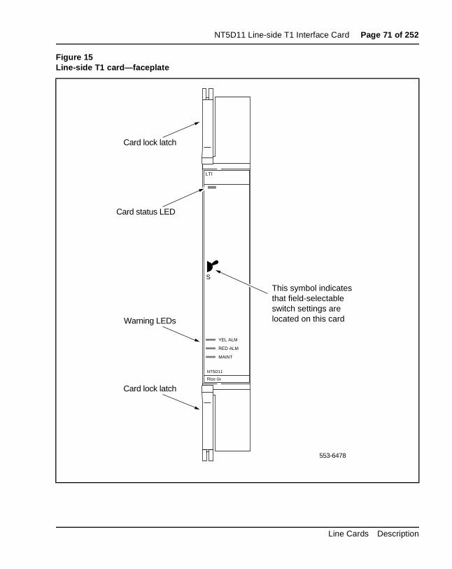
NT5D11 Line-side T1 Interface Card Page 71 of 252
Figure 15Line-side T1 card—faceplate
YEL ALM
RED ALM
MAINT
S
LTI
Rlse 0x
NT5D11
Card lock latch
Card lock latch
Warning LEDs
This symbol indicatesthat field-selectableswitch settings arelocated on this card
Card status LED
553-6478
Line Cards Description
Page 72 of 252 NT5D11 Line-side T1 Interface Card
of
must the the l
n
eded
m larm
his
e as
ed ee
red
slip
ure.
Note: Note: The STATUS LED indicates the enabled/disabled statusboth card slots of the line-side T1 card simultaneously. To properly enable the card, both the motherboard and the daughterboard slots be enabled. The STATUS LED will turn out as soon as either one of line-side T1 card slots have been enabled. No LED operation will beobserved when the second card slot is enabled. To properly disablecard, both card slots must be disabled. The LED will not turn on untiboth card slots have been disabled.
The RED ALARM LED indicates that the line-side T1 card has detected aalarm condition from the T1 link. Alarm conditions include, but are not limited to, such conditions as not receiving a signal or the signal has excebit error thresholds or frame slip thresholds. (See “Man-Machine T1 maintenance interface software” on page 102 for information on T1 link maintenance.)
If one of these alarm conditions is detected, this LED will light. Yellow alarindication is sent to the far end as long as the near end remains in a red acondition. Depending on how the Man-Machine Interface (MMI) is configured, this LED will remain lit until the following actions occur:
• If the “Self-Clearing” function has been enabled in the MMI, the LEDwill clear the alarm when the alarm condition is no longer detected (tis the factory default condition).
• If the “Self-Clearing” function has not been enabled or it has been subsequently disabled in the MMI, the LED will stay lit until the command “Clear Alarm” has been typed in the MMI, even though thcarrier automatically returned to service when the alarm condition wno longer detected.
The YELLOW ALARM LED indicates that the line-side T1 card has detecta yellow alarm signal from the terminal equipment side of the T1 link. (Sthe “Man-Machine T1 maintenance interface software” on page 102 for information on T1 link maintenance.) If the terminal equipment detects a alarm condition (including, but not limited to, such conditions as not receiving a signal or the signal has exceeded bit error thresholds or framethresholds), it may send a yellow alarm signal to the line-side T1 card, depending on whether or not your terminal equipment supports this featIf a yellow alarm signal is detected, this LED will light.
553-3001-105 Standard 6.00 April 2000
NT5D11 Line-side T1 Interface Card Page 73 of 252
al MI. r ing ht me
The MAINT LED indicates whether the line-side T1 card is fully operationbecause of certain maintenance commands being issued through the M(See “Man-Machine T1 maintenance interface software” on page 102 foinformation on T1 link maintenance.) If the card detects that tests are berun or that alarms have been disabled through the MMI, this LED will ligand will remain lit until these conditions are no longer detected, at which tiit will turn off.
Line Cards Description
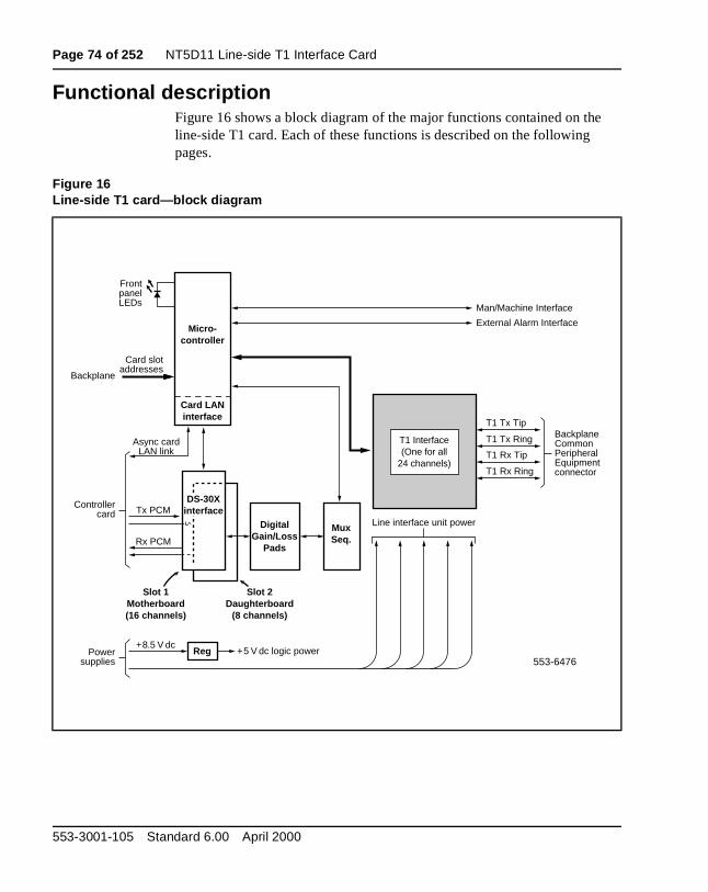
Page 74 of 252 NT5D11 Line-side T1 Interface Card
e
Functional descriptionFigure 16 shows a block diagram of the major functions contained on thline-side T1 card. Each of these functions is described on the following pages.
Figure 16Line-side T1 card—block diagram
Micro-controller
Tx PCM
Async cardLAN link
FrontpanelLEDs
Card LANinterface
T1 Interface(One for all
24 channels)
Line interface unit power
Rx PCM
Controllercard
DigitalGain/Loss
Pads
Slot 1Motherboard(16 channels)
Slot 2Daughterboard
(8 channels)
MuxSeq.
Reg553-6476
Powersupplies
+8.5 V dc+5 V dc logic power
T1 Tx Tip
Man/Machine Interface
External Alarm Interface
T1 Tx Ring
T1 Rx Tip
T1 Rx Ring
BackplaneCommonPeripheralEquipmentconnector
Card slotaddresses
Backplane
DS-30Xinterface
553-3001-105 Standard 6.00 April 2000
NT5D11 Line-side T1 Interface Card Page 75 of 252
rd le ding
line ed e
ble
an s are
us s
as
e in a
nect ive
T1 ns
often
dard
or
OverviewThe line-side T1 card is an intelligent peripheral equipment (IPE) line cathat provides a cost-effective all-digital connection between T1 compatibterminal equipment (such as voice mail systems, voice response units, traturrets, etc.) and a Meridian 1 system. In this application the terminal equipment can be assured access to analog (500/2500) telephone type functionality such as hook flash, spre codes and ringback tones generatfrom the Meridian 1. In most cases, the line-side T1 card will eliminate thneed for channel bank type equipment normally placed between the Meridian 1 and the terminal equipment, providing a more robust and reliaend-to-end connection. The line-side T1 card supports line supervision features such as loop and ground start protocols. It may also be used inoff-premise arrangement whereby analog (500/2500) telephone type setextended over T1 with the use of channel bank equipment.
The line-side T1 interface offers significant improvement over the previoalternatives. For example, if a digital trunk connection were used, such awith the DTI/PRI interface card, line-side functionality would not be supported. Previously, the only way to achieve the line-side functionality wto use analog ports and channel bank equipment. With the line-side T1 interface, a direct connection is provided between the Meridian 1 and thperipheral equipment. No channel bank equipment is required, resultingmore robust and reliable connection.
The line-side T1 interface offers a number of benefits when used to cona Meridian 1 to third-party applications equipment. It is a more cost-effectalternative for connection because it eliminates the need for expensive channel bank equipment. In addition, the line-side T1 supports powerfulmonitoring and diagnostic capability. Overall costs for customer applicatiomay also be reduced because the T1-compatible peripheral equipment ismore attractively priced than the analog-port alternatives.
The line-side T1 card is compatible with all IPE based systems and stanpublic or private DSX-1 type carrier facilities. Using A/B robbed bit signaling, it supports D4 or ESF channel framing formats as well as AMIB8ZS coding. Because it uses standard PCM in standard T1 timeslots, existing T1 test equipment remains compatible for diagnostic and fault isolation purposes.
Line Cards Description
Page 76 of 252 NT5D11 Line-side T1 Interface Card
s ard al
24 e
T1 ing
g
k lls. and
on e
Card interfacesThe line-side T1 card passes voice and signaling data over DS-30X loopthrough the DS-30X Interfaces circuits and maintenance data over the cLAN link. These interfaces are discussed in detail in “Intelligent peripherequipment” on page 17.
T1 interface circuitThe line-side T1 card contains one T1 line interface circuit that providesindividually configurable voice interfaces to one T1 link in 24 different timslots. The circuit demultiplexes the 2.56 Mbps DS-30X Tx signaling bitstreams from the DS-30X network loop and converts it into 1.544 mHzTx signaling bitstreams onto the T1 link. It also does the opposite, receivRx signaling bitstreams from the T1 link and transmitting Rx signaling bitstreams onto the DS-30X network loop.
The line interface circuit performs the following:
• Provides an industry standard DSX-1 (0 to 655 feet) interface.
• Converts DS-30X signaling protocol into FXO A and B robbed bit signaling protocol.
• Provides switch-selectable transmission and reception of T1 signalinmessages over a T1 link in either loop or ground start mode.
Signaling and controlThe line-side T1 card also contains signaling and control circuits that establish, supervise, and take down call connections. These circuits worwith the system controller to operate the T1 line interface circuit during caThe circuits receive outgoing call signaling messages from the controller return incoming call status information to the controller over the DS-30Xnetwork loop.
Card control functionsControl functions are provided by a microcontroller and a Card LAN link the line-side T1 card. A sanity timer is provided to automatically reset thcard if the microcontroller stops functioning for any reason.
553-3001-105 Standard 6.00 April 2000
NT5D11 Line-side T1 Interface Card Page 77 of 252
nal he
ons
ard
t
nd will
MicrocontrollersThe line-side T1 card contains two microcontrollers that control the interoperation of the card and the serial card LAN link to the controller card. Tmicrocontrollers control the following:
• reporting to the CE CP via the card LAN link:
— card identification (card type, vintage, serial number)
— firmware version
— self-test results
— programmed unit parameter status
• receipt and implementation of card configuration:
— control of the T1 line interfaces
— enabling/disabling of individual units or entire card
— programming of loop interface control circuits for administration of channel operation
— maintenance diagnostics
• interface with the line card circuit:
— converts on/off-hook, and ringer control messages from the DS-30X loop into A/B bit manipulations for each time slot in the T1 data stream, using robbed bit signaling.
• the front panel LED when the card is enabled or disabled by instructifrom the NT8D01 controller card.
Card LAN interfaceMaintenance data is exchanged with the Common Equipment CP over adedicated asynchronous serial network called the Card LAN link. The CLAN link is described in “Card LAN link” on page 20.
Sanity timerThe line-side T1 card also contains a sanity timer that resets the microcontroller in the event of a loss of program control. If the timer is noproperly serviced by the microcontroller, it times out and causes the microcontroller to be hardware reset. If the microcontroller loses control afails to service the sanity timer at least once per second, the sanity timerautomatically reset the microcontroller, restoring program control.
Line Cards Description
Page 78 of 252 NT5D11 Line-side T1 Interface Card
s.
the d
T1
Man-Machine Interface (MMI)The line-side T1 card provides an optional man-machine interface that isprimarily used for T1 link performance monitoring and problem diagnosiThe MMI provides alarm notification, T1 link performance reporting and fault isolation testing. The interface is accessed through connections fromI/O panel to a terminal or modem. Multiple cards (up to 64) can be servethrough one MMI terminal or modem by cabling the cards together.
The MMI is an optional feature since all T1 configuration settings are performed through dip switch settings or preconfigured factory default settings. The man-machine interface is discussed fully in “Man-Machine maintenance interface software” on page 102.
553-3001-105 Standard 6.00 April 2000
NT5D11 Line-side T1 Interface Card Page 79 of 252
e 15
tic is the
ne.
of
Electrical specificationsTable 14 provides a technical summary of the T1 line interfaces, and Tabllists the maximum power consumed by the card.
T1 channel specificationsTable 14 provides specifications for the 24 T1channels. Each characterisset by dip switches. See “Installation and Configuration” on page 81 for corresponding dip switch settings.
Power requirementsThe line-side T1 card requires +15 V, –15 V, and +5 V from the backplaOne NT8D06 Peripheral Equipment Power Supply AC or NT6D40 Peripheral Equipment Power Supply DC can supply power to a maximumeight line-side T1 cards.
Table 14Line-side T1 card—line interface unit electrical characteristics
Characteristics Description
Framing ESF or D4
Coding AMI or B8ZS
Signaling Loop or ground start A/B robbed-bit
Distance to Customer Premise Equipment (CPE) or Channel Service Unit
0-199.6 meters (0–655 feet)
Table 15Line-side T1 card—power required
Voltage Current (max.)
+ 5.0 V dc 1.6 Amp
+15.0 V dc 150 mA.
–15.0 V dc 150 mA.
Line Cards Description

Page 80 of 252 NT5D11 Line-side T1 Interface Card
on tal
the f
.
Foreign and surge voltage protectionsIn-circuit protection against power line crosses or lightning is not providedthe line-side T1 card. It does, however, have protection against accidenshorts to –52 V dc analog lines.
When the card is used to service off-premise terminal equipment throughpublic telephone network, install a Channel Service Unit (CSU) as part oyour terminal equipment to provide external line protection.
Environmental specificationsTable 16 shows the environmental specifications of the line-side T1 card
Table 16Line-side T1 card—environmental specifications
Parameter Specifications
Operating temperature-normal 15° to +30° C (+59° to 86°F), ambient
Operating temperature-short term 10° to +45° C (+50° to 113°F), ambient
Operating humidity-normal 20% to 55% RH (non-condensing)
Operating humidity-short term 20% to 80% RH (non-condensing)
Storage temperature –50° to +70° C (–58° to 158°F), ambient
Storage humidity 5% to 95% RH (non-condensing)
553-3001-105 Standard 6.00 April 2000
NT5D11 Line-side T1 Interface Card Page 81 of 252
ic
elf.
) or d
T1
ing d are n in h 20.
hes
or
Installation and ConfigurationInstallation and configuration of the line-side T1 card consists of six bassteps:
1 Configure the dip switches on the line-side T1 card for your environment.
2 Install the line-side T1 card into the selected card slots in the IPE sh
3 Cable from the I/O panel to the Customer Premise Equipment (CPECSU, MMI terminal or modem (optional), external alarm (optional), another line-side T1 cards for daisy chaining use of MMI terminal (optional).
4 Configure the MMI terminal.
5 Configure the line-side T1 card through the Meridian 1 software andverify self-test results.
6 Verify initial T1 operation and configure MMI (optional).
Steps 1-5 are explained in this section. Step 6 is covered in “Man-Machinemaintenance interface software” on page 102.
Dip switch settingsBegin your installation and configuration of the line-side T1 card by selectthe proper dip switch settings for your environment. The line-side T1 carcontains two dip switches, each containing eight switch positions. They located in the upper right corner of the motherboard circuit card as showFigure 17. The settings for these switches are shown in Tables 17 throug
When the line-side T1 card is oriented as shown in Figure 17, the dip switcare ON when they are up, and OFF when they are down. The dip switchsettings configure your card for the following parameters:
MMI port speed selectionThis dip switch setting selects the appropriate baud rate for the terminalmodem (if any) that is connected to your MMI.
Line Cards Description
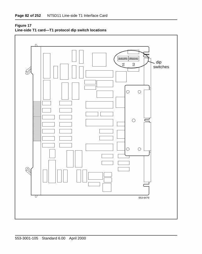
Page 82 of 252 NT5D11 Line-side T1 Interface Card
Figure 17Line-side T1 card—T1 protocol dip switch locations
553-6479
S1
S2 dip
switches
553-3001-105 Standard 6.00 April 2000
NT5D11 Line-side T1 Interface Card Page 83 of 252
1 des. e
d. The e;
) it is ipheral
be
ent h
ent orts.
Line Supervisory Signaling protocolAs described in “Line-side T1 call operation” on page 33, the line-side Tcard is capable of supporting loop start or ground start call processing moMake your selection for this dip switch position based on what type of linsignaling your CPE equipment supports.
Address of line-side T1 card to the MMIThe address of the line-side T1 card to the MMI is made up of two components:
• The address of the card within the shelf
• The address of the shelf in which the card resides
These two addresses are combined create a unique address for the carMMI reads the address of the card within the shelf from the card firmwarhowever the address of the shelf must be set by this dip switch.
The shelf address dip switch can be from 0-15, 16 being the maximum number of line-side T1 IPE shelves (a maximum of 64 line-side T1 cardscapable of daisy chaining to a single MMI terminal. For clarity and ease, recommended that this address be set the same as the address of the percontroller identifier in overlay 97 for type: XPE. However, this is not mandatory, and, since the dip switch is limited to 16, this will not alwayspossible.
T1 framingThe line-side T1 card is capable of interfacing with CPE or CSU equipmeither in D4 or ESF framing mode. Make your selection for this dip switcposition based on what type of framing your CPE or CSU equipment supports.
T1 CodingThe line-side T1 card is capable of interfacing with CPE or CSU equipmusing either AMI or B8ZS coding. Make your selection for this dip switchposition based on what type of coding your CPE or CSU equipment supp
Line Cards Description
Page 84 of 252 NT5D11 Line-side T1 Interface Card
ocal ide
will
the
this ling.
e in t is
if
DSX-1 lengthEstimate the distance between the line-side T1 card and the hardwired lCPE or the Telco demarc RJ48 for the carrier facility connecting the line-sT1 and the remote CPE. Make your selection for this dip switch positionbased on this distance.
Line supervision on T1 failureThis setting determines in what state all 24 ports of the line-side T1 card appear to the Meridian 1 in case of T1 failure. Ports can appear to the Meridian 1 as either in the on-hook or off-hook states on T1 failure.
Note: All idle line-side T1 lines will go off-hook and seize a DigitoneReceiver when the off-hook line processing is invoked on T1 failure.This may prevent DID trunks from receiving incoming calls until the line-side T1 lines time-out and release the DTRs.
Daisy-Chaining to MMI If you plan to install two or more line-side T1 cards and you plan to use MMI, you will want to daisy-chain your cards together to use one MMI terminal or modem (see Figure 19 on page 98). Make your selection for dip switch position based on how many line-side T1 cards you are instal
MMI Master or SlaveThis setting is used only if you are daisy-chaining your cards to the MMIterminal or modem. It determines whether this card is a master or a slavyour MMI daisy-chain. Select the master setting if this card is the card thacabled directly into the MMI terminal or modem; select the slave setting this card is cabled to another line-side T1 card in a daisy chain.
553-3001-105 Standard 6.00 April 2000
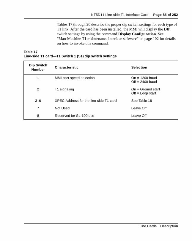
NT5D11 Line-side T1 Interface Card Page 85 of 252
e of
ils
Tables 17 through 20 describe the proper dip switch settings for each typT1 link. After the card has been installed, the MMI will display the DIP switch settings by using the command Display Configuration. See “Man-Machine T1 maintenance interface software” on page 102 for detaon how to invoke this command.
Table 17Line-side T1 card—T1 Switch 1 (S1) dip switch settings
Dip Switch Number
Characteristic Selection
1 MMI port speed selection On = 1200 baudOff = 2400 baud
2 T1 signaling On = Ground startOff = Loop start
3–6 XPEC Address for the line-side T1 card See Table 18
7 Not Used Leave Off
8 Reserved for SL-100 use Leave Off
Line Cards Description
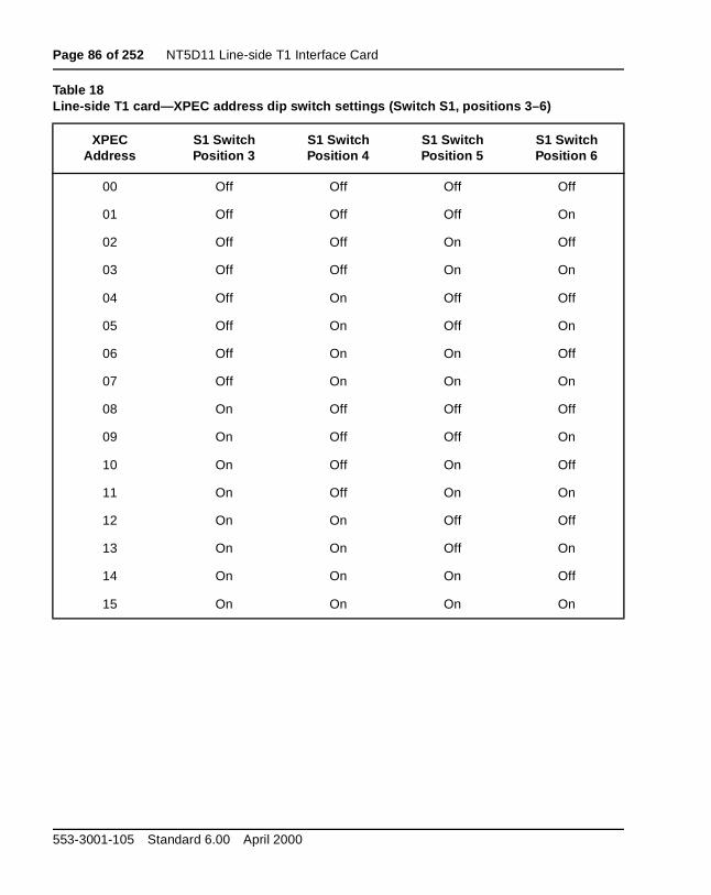
Page 86 of 252 NT5D11 Line-side T1 Interface Card
Table 18Line-side T1 card—XPEC address dip switch settings (Switch S1, positions 3–6)
XPECAddress
S1 SwitchPosition 3
S1 SwitchPosition 4
S1 SwitchPosition 5
S1 SwitchPosition 6
00 Off Off Off Off
01 Off Off Off On
02 Off Off On Off
03 Off Off On On
04 Off On Off Off
05 Off On Off On
06 Off On On Off
07 Off On On On
08 On Off Off Off
09 On Off Off On
10 On Off On Off
11 On Off On On
12 On On Off Off
13 On On Off On
14 On On On Off
15 On On On On
553-3001-105 Standard 6.00 April 2000
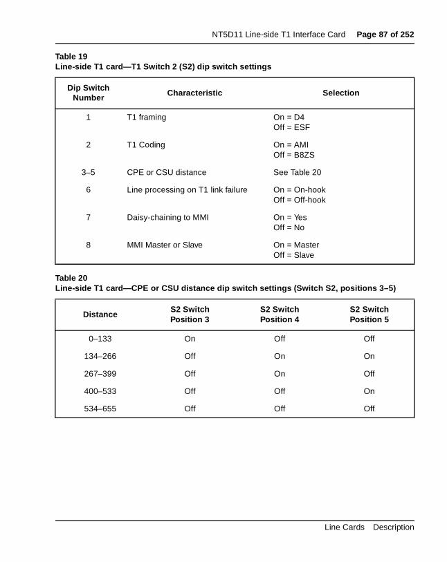
NT5D11 Line-side T1 Interface Card Page 87 of 252
Table 19Line-side T1 card—T1 Switch 2 (S2) dip switch settings
Dip Switch Number Characteristic Selection
1 T1 framing On = D4Off = ESF
2 T1 Coding On = AMIOff = B8ZS
3–5 CPE or CSU distance See Table 20
6 Line processing on T1 link failure On = On-hookOff = Off-hook
7 Daisy-chaining to MMI On = YesOff = No
8 MMI Master or Slave On = MasterOff = Slave
Table 20Line-side T1 card—CPE or CSU distance dip switch settings (Switch S2, positions 3–5)
DistanceS2 SwitchPosition 3
S2 SwitchPosition 4
S2 SwitchPosition 5
0–133 On Off Off
134–266 Off On On
267–399 Off On Off
400–533 Off Off On
534–655 Off Off Off
Line Cards Description
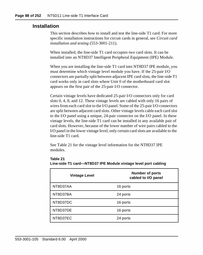
Page 88 of 252 NT5D11 Line-side T1 Interface Card
ore
ou
e T1
rd of tors d slot ese r of the
the
InstallationThis section describes how to install and test the line-side T1 card. For mspecific installation instructions for circuit cards in general, see Circuit card installation and testing (553-3001-211).
When installed, the line-side T1 card occupies two card slots. It can be installed into an NT8D37 Intelligent Peripheral Equipment (IPE) Module.
When you are installing the line-side T1 card into NT8D37 IPE module, ymust determine which vintage level module you have. If the 25-pair I/O connectors are partially split between adjacent IPE card slots, the line-sidcard works only in card slots where Unit 0 of the motherboard card slot appears on the first pair of the 25-pair I/O connector.
Certain vintage levels have dedicated 25-pair I/O connectors only for caslots 0, 4, 8, and 12. These vintage levels are cabled with only 16 pairs wires from each card slot to the I/O panel. Some of the 25-pair I/O connecare split between adjacent card slots. Other vintage levels cable each carto the I/O panel using a unique, 24-pair connector on the I/O panel. In thvintage levels, the line-side T1 card can be installed in any available paicard slots. However, because of the lower number of wire pairs cabled toI/O panel in the lower vintage level, only certain card slots are available toline-side T1 card.
See Table 21 for the vintage level information for the NT8D37 IPE modules.
Table 21Line-side T1 card—NT8D37 IPE Module vintage level port cabling
Vintage LevelNumber of ports
cabled to I/O panel
NT8D37AA 16 ports
NT8D37BA 24 ports
NT8D37DC 16 ports
NT8D37DE 16 ports
NT8D37EC 24 ports
553-3001-105 Standard 6.00 April 2000
NT5D11 Line-side T1 Interface Card Page 89 of 252
e
Available and restricted card slots in the NT8D37 IPE Module
If you are installing the line-side T1 card into an NT8D37 IPE Module, thcard slots available depend on what vintage level module you have.
Vintage levels cabling 24 portsFor modules with vintage levels that cabled 24 ports to the I/O panel, theline-side T1 card can be installed in any pair of card slots 015.
Line Cards Description
Page 90 of 252 NT5D11 Line-side T1 Interface Card
can
t ing to
Vintage levels cabling 16 portsFor modules with vintage levels that cabled 16 ports to the I/O panel, youinstall the line-side T1 card into the following card slot pairs:
You cannot install the line-side T1 card into the following card slot pairs:
If you must install the line-side T1 card into one of the restricted card slopairs, you can rewire your IPE module card slot to the I/O panel by installan additional NT8D81 cable from the line-side T1 card motherboard slotthe I/O panel, and re-arranging the three backplane connectors for the affected card slots. This will permit the connection of the NT5D13AA Line-side T1 card carrier and maintenance external I/O cable at the IPEmodule I/O panel connector for card slots that are otherwise restricted.
Alternatively, all line-side T1 card connections can be made at the main distribution frame instead of connecting the NT5D13 Line-side T1 card external I/O cable at the I/O panel. This eliminates these card slots restrictions.
Available: Motherboard/Daughterboard
0 and 1
1 and 2
4 and 5
7 and 8
8 and 9
9 and 10
12 and 13
13 and 14
Restricted: Motherboard/Daughterboard
2 and 3
3 and 4
6 and 7
10 and 11
11 and 12
14 and 15
553-3001-105 Standard 6.00 April 2000
NT5D11 Line-side T1 Interface Card Page 91 of 252
the E or
rds
are l on the ith
nd ee one B15 P3) (P5) tor isy
Cabling the line-side T1 cardAfter you have set the dip switches and installed the line-side T1 card intoselected card slots, you are ready to cable the line-side T1 card to the CPCSU equipment. You can also make connections to the MMI terminal ormodem (optional), an external alarm (optional), and other line-side T1 cafor daisy-chain use of the MMI terminal (optional).
The line-side T1 card is cabled from its backplane connector through connections from the motherboard circuit card only (no cable connectionsmade from the daughterboard circuit card) to the input/output (I/O) panethe rear of the IPE module. The connections from the line-side T1 card toI/O panel are made with the NT8D81AA Tip and Ring cables provided wthe IPE module.
Cabling from the I/O panel with the NT5D13AA Line-side T1 I/O cableNormally you will make the connection from the I/O panel to the T1 link aother external devices through the NT5D13AA Line-side T1 I/O cable (sFigure 18). This cable consists of a 25-pair amphenol connector (P1) onend which plugs into the I/O panel. The other end has 4 connectors: a Dmale connector (P2) which plugs into the T1 line, a DB9 male connector (which plugs into an external alarm system, a second DB9 male connectorwhich connects to an MMI terminal or modem, and a DB9 female connec(P4) that connects to the next line-side T1 card’s P4 connector for MMI dachaining.
Line Cards Description
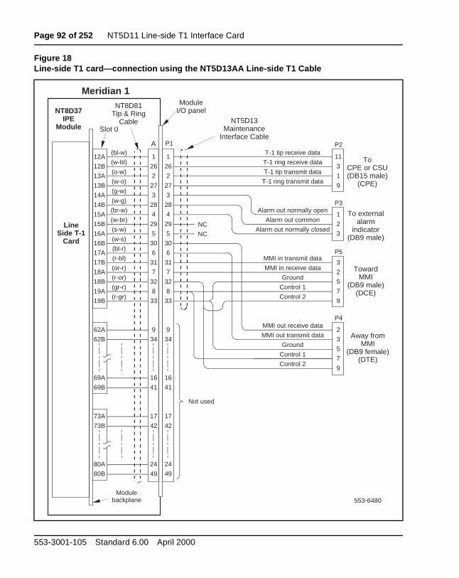
Page 92 of 252 NT5D11 Line-side T1 Interface Card
Figure 18Line-side T1 card—connection using the NT5D13AA Line-side T1 Cable
553-6480
NT8D37 IPE
Module Slot 0
ModuleI/O panel
1
26
2
27
3
28
4
29
5
30
6
31
7
32
8
33
9
34
16
41
17
42
24
49
Meridian 1
A(bl-w)
(w-bl)
(o-w)
(w-o)
(g-w)
(w-g)
(br-w)
(w-br)
(s-w)
(w-s)
(bl-r)
(r-bl)
(or-r)
(r-or)
(gr-r)
(r-gr)
NT8D81 Tip & Ring
Cable
12A
12B
13A
13B
14A
14B
15A
15B
16A
16B
17A
17B
18A
18B
19A
19B
62A
62B
69A
69B
73A
73B
80A
80B
Line Side T-1
Card
Not used
T-1 tip receive data
T-1 ring receive data
T-1 tip transmit data
T-1 ring transmit data
Alarm out normally open
Alarm out common
Alarm out normally closed
MMI in transmit data
MMI in receive data
Ground
Control 1
Control 2
MMI out receive data
MMI out transmit data
Ground
Control 1
Control 2
11
3
1
9
1
2
3
3
2
5
7
9
2
3
5
7
9
1
26
2
27
3
28
4
29
5
30
6
31
7
32
8
33
9
34
16
41
17
42
24
49
P2
P3
P5
P4
To CPE or CSU(DB15 male)
(CPE)
To external alarm
indicator(DB9 male)
TowardMMI
(DB9 male)(DCE)
Away from MMI
(DB9 female)(DTE)
NT5D13 Maintenance
Interface Cable
Module backplane
NC
NC
P1
553-3001-105 Standard 6.00 April 2000
NT5D11 Line-side T1 Interface Card Page 93 of 252
e w
ect
that an
in
.
pins. d the ns are
d at . See
de
Cabling from the I/O panel at the Main Distribution FrameYou may also choose to make all line-side T1 connections at the main distribution frame (MDF) if you prefer not to use the NT5D13AA Line-sidT1 I/O cable at the I/O panel. To make the connections at the MDF, follothis procedure:
1 Punch down the first eight pairs of a standard telco 25-pair female-connectorized cross-connect tail starting with the first tip andring pair of the line-side T1 motherboard card slot on the cross-connside of the MDF terminals.
2 Plug the NT5D13AA Line-side T1 I/O cable into this 25-pair cross-connect tail at the MDF, regardless of the card slot restrictions exist from the vintage level of IPE or CE/PE module you have. You calso make this connection at the MDF without using the NT5D13 Line-side T1 I/O cable, by cross-connecting according to the pinoutsTable 22.
3 Turn over the T1 transmit and receive pairs, where required for hardwiring the line-side T1 card to local CPE T1 terminal equipment
The backplane connector is arranged as an 80-row by 2-column array of Table 22 shows the I/O pin designations for the backplane connector an25-pair Amphenol connector from the I/O panel. Although the connectiofrom the I/O panel only use 14 of the available 50 pins, the remaining pinsreserved and cannot be used for other signaling transmissions.
The information in Table 22 is provided as a reference and diagnostic aithe backplane, since the cabling arrangement may vary at the I/O panelSystem Installation Procedures (553-3001-210) for cable pinout informationfor the I/O panel.
Table 23 shows the pin assignments when using the NT5D13AA Line-siT1 I/O cable.
Line Cards Description
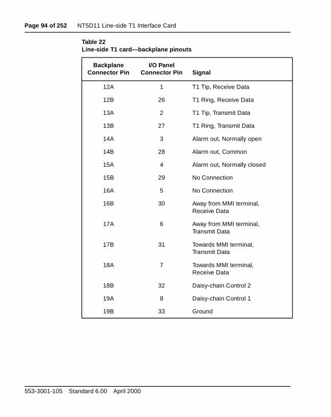
Page 94 of 252 NT5D11 Line-side T1 Interface Card
Table 22Line-side T1 card—backplane pinouts
Backplane Connector Pin
I/O PanelConnector Pin Signal
12A 1 T1 Tip, Receive Data
12B 26 T1 Ring, Receive Data
13A 2 T1 Tip, Transmit Data
13B 27 T1 Ring, Transmit Data
14A 3 Alarm out, Normally open
14B 28 Alarm out, Common
15A 4 Alarm out, Normally closed
15B 29 No Connection
16A 5 No Connection
16B 30 Away from MMI terminal,Receive Data
17A 6 Away from MMI terminal,Transmit Data
17B 31 Towards MMI terminal,Transmit Data
18A 7 Towards MMI terminal,Receive Data
18B 32 Daisy-chain Control 2
19A 8 Daisy-chain Control 1
19B 33 Ground
553-3001-105 Standard 6.00 April 2000
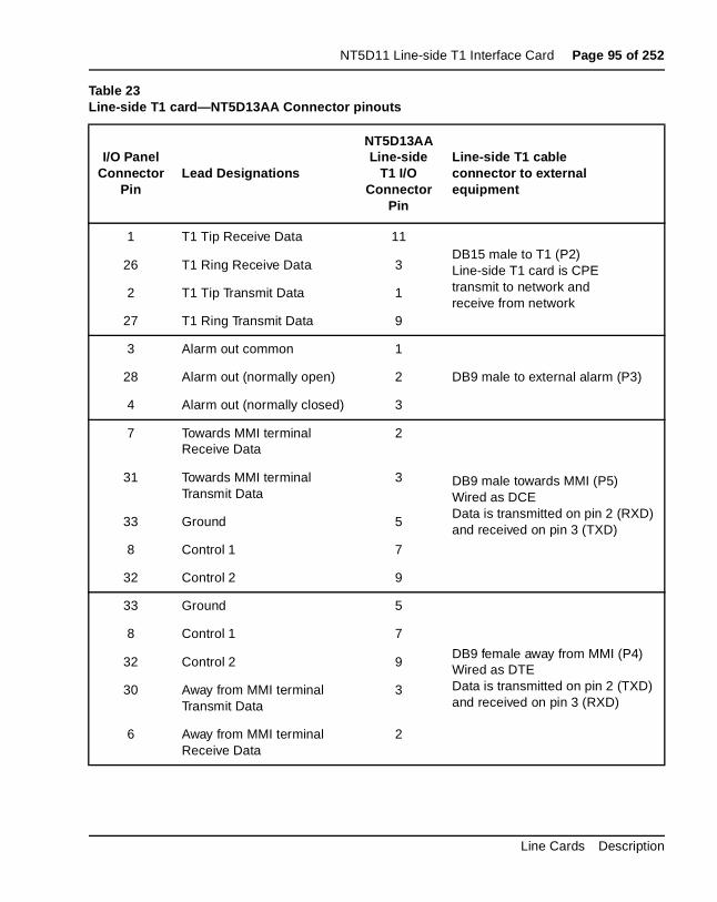
NT5D11 Line-side T1 Interface Card Page 95 of 252
Table 23Line-side T1 card—NT5D13AA Connector pinouts
I/O PanelConnector
PinLead Designations
NT5D13AALine-side
T1 I/OConnector
Pin
Line-side T1 cableconnector to external equipment
1 T1 Tip Receive Data 11DB15 male to T1 (P2)Line-side T1 card is CPEtransmit to network andreceive from network
26 T1 Ring Receive Data 3
2 T1 Tip Transmit Data 1
27 T1 Ring Transmit Data 9
3 Alarm out common 1
DB9 male to external alarm (P3)28 Alarm out (normally open) 2
4 Alarm out (normally closed) 3
7 Towards MMI terminalReceive Data
2
DB9 male towards MMI (P5)Wired as DCEData is transmitted on pin 2 (RXD)and received on pin 3 (TXD)
31 Towards MMI terminalTransmit Data
3
33 Ground 5
8 Control 1 7
32 Control 2 9
33 Ground 5
DB9 female away from MMI (P4)Wired as DTEData is transmitted on pin 2 (TXD)and received on pin 3 (RXD)
8 Control 1 7
32 Control 2 9
30 Away from MMI terminalTransmit Data
3
6 Away from MMI terminalReceive Data
2
Line Cards Description
Page 96 of 252 NT5D11 Line-side T1 Interface Card
, 9, 2” en
er the
rm. ard
if it r 2. r a or
I .
rd to to a s the ol 1” I ted
T1 connectionsT1 signaling for all 24 channels is transmitted over P2 connector pins 1, 3and 11 as shown in Table 23. Plug the DB15 male connector labeled “Pinto the T1 link. T1 transmit and receive pairs must be turned over betwethe line-side T1 card and CPE equipment that is hardwired without carrifacilities. If the line-side T1 card is connected via T1 carrier facilities, thetransmit and receive pairs must be wired straight through to the RJ48 atTelco demarc, the CSU, or other T1 carrier equipment. The T1 CPE equipment at the far end will likewise have transmit and receive wired straight from the RJ48 demarc at the far end of the carrier facility.
External alarm connectionsP3 connector pins 3, 4, and 28 can be plugged into any external alarm hardware. Plug the male DB9 connector labeled “P3” into the external alaThese connections are optional, and the functionality of the line-side T1 cis not affected if they are not made.
The MMI (described in detail in “Man-Machine T1 maintenance interfacesoftware” on page 102) monitors the T1 link for specified performance criteria and reports on problems detected. One of the ways it can reportinformation is through this external alarm connection. If connected, the line-side T1 card’s microprocessor activates the external alarm hardwaredetects certain T1 link problems that it has classified as alarm levels 1 o(See “Man-Machine T1 maintenance interface software” on page 102 fodetailed description of alarm levels and configuration.) If an alarm level 12 is detected by MMI, the line-side T1 card will close the contact that is normally open, and will open the contact that is normally closed. The MMcommand Clear Alarm will return the alarm contacts to their normal state
MMI connectionsP5 connector pins 2, 3, 5, 7 and 9 are used to connect the line-side T1 cathe MMI terminal and daisy chain line-side T1 cards together for access shared MMI terminal. When you log into a line-side T1 card, “control 2” iasserted by that card, which informs all of the other cards not to talk on bus, but rather to pass the data straight through. The pins labeled “contrare reserved for future use. As with the external alarm connections, MMconnections are optional. You can link up to 128 line-side T1 cards, locain up to 16 separate IPE shelves, to one MMI terminal using the daisy chaining approach.
553-3001-105 Standard 6.00 April 2000
NT5D11 Line-side T1 Interface Card Page 97 of 252
on
B9
nly in can lot; this al:
to nal
ing
n to
nd lf at
If you are installing only one line-side T1 card, cable from the DB9 femaleconnector labeled “P5” (towards MMI terminal) to one of the COM ports the back of any TTY, a PC running a terminal emulation program, or a modem. For installations of only one card, no connection is made to the Dmale connector labeled “P4” (away from MMI terminal).
If you are installing two or more line-side T1 cards into your Meridian 1 system, you can daisy-chain the MMI port connections together so that oone MMI terminal is required for up to 128 line-side T1 cards (as shown Figure 19). Cards can be located in up to 16 separate IPE shelves. You start with any card slot in your IPE shelf and connect to any other card sthe card slots connected together do not need to be consecutive. Followprocedure for connecting two or more line-side T1 cards to the MMI termin
1 Cable the DB9 male connector labeled “P5” (towards MMI terminal) one of the COM ports on the back of any TTY, a PC running a termiemulation program, or a modem.
2 Make the connection from the first card to the second card by pluggthe DB9 female connector labeled “P4” (away from MMI terminal) fromthe first card into the DB9 male connector of the second card labeled“P5” (towards MMI terminal).
3 Repeat Step 2 for the remaining cards.
4 When you get to the last card in your daisy chain, make no connectiothe DB9 male connector labeled “P4” (away from MMI terminal).
5 If two line-side T1 cards are located too far apart to connect the “P4” a“P5” connectors together, connect them together with an off-the-sheDB-9 female to DB-9 male straight through extension cable, availableany PC supply store.
Line Cards Description
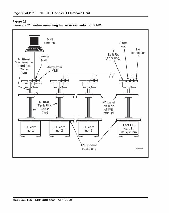
Page 98 of 252 NT5D11 Line-side T1 Interface Card
Figure 19Line-side T1 card—connecting two or more cards to the MMI
553-6481
Noconnection
LTI card no. 1
LTI card no. 2
LTI card no. 3
Last LTI card in
daisy chain
MMI terminal
IPE module backplane
I/O panel on rear of IPE
module
NT5D13 Maintenance
Interface Cable (typ)
LTITx & Rx
(tip & ring)
Alarm out
TowardMMI
Away fromMMI
NT8D81 Tip & Ring
Cable (typ)
P1
P2 P3 P4P5
553-3001-105 Standard 6.00 April 2000
NT5D11 Line-side T1 Interface Card Page 99 of 252
the
n 1
ide een
ause e as
am
and oard ard
de t 0
the to
Terminal configurationFor the MMI terminal to be able to communicate to the line-side T1 card, interface characteristics must be set to:
• Speed - 1200 or 2400 bps, depending on the setting of switch positioof Switch 1
• Character width - 8 bits
• Parity bit - none
• Stop bits - one
• Software handshake (XON/XOFF) - off
Software configurationAlthough much of the architecture and many of the features of the line-sT1 card are different from the analog line card, the line-side T1 card has bdesigned to emulate an analog line card to the Meridian 1 software. Becof this, the line-side T1 card software configuration is performed the saman two adjacent analog line cards.
All 24 T1 channels carried by the line-side T1 card are individually configured using the Analog (500/2500) Telephone Administration progr(LD 10). Use Table 24 to determine the correct unit number and the X11 input/output guide (553-3001-400) for LD 10 service change instructions.
The line-side T1 card circuitry routes 16 units (0-15) on the motherboard eight (0-7) units on the daughterboard to 24 T1 channels. The motherbcircuit card is located in the left card slot, and the daughterboard circuit cis located in right card slot. For example, if you were to install the line-siT1 card into card slots 0 and 1, the motherboard would reside in card sloand the daughterboard would reside in card slot 1. In order to configure terminal equipment through the switch software, you will need to be ablecross-reference the T1 channel number to the corresponding card unit number. This mapping is shown in Table 24.
Line Cards Description
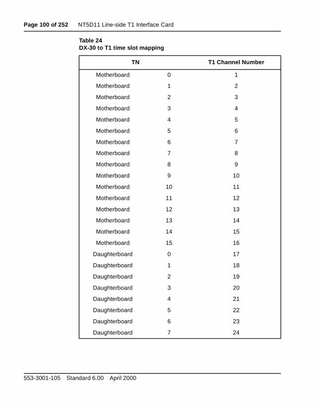
Page 100 of 252 NT5D11 Line-side T1 Interface Card
Table 24DX-30 to T1 time slot mapping
TN T1 Channel Number
Motherboard 0 1
Motherboard 1 2
Motherboard 2 3
Motherboard 3 4
Motherboard 4 5
Motherboard 5 6
Motherboard 6 7
Motherboard 7 8
Motherboard 8 9
Motherboard 9 10
Motherboard 10 11
Motherboard 11 12
Motherboard 12 13
Motherboard 13 14
Motherboard 14 15
Motherboard 15 16
Daughterboard 0 17
Daughterboard 1 18
Daughterboard 2 19
Daughterboard 3 20
Daughterboard 4 21
Daughterboard 5 22
Daughterboard 6 23
Daughterboard 7 24
553-3001-105 Standard 6.00 April 2000
NT5D11 Line-side T1 Interface Card Page 101 of 252
the
e for
th lso nal e ct
ard , and r
ill are. uld
Disconnect supervisionThe line-side T1 card supports far end disconnect supervision by openingtip side toward the terminal equipment upon the Meridian 1 system's detecting a disconnect signal from the far end on an established call. ThSupervised Analog Line Feature (SAL) must be configured in overlay 10each line-side T1 port. At the prompt FTR respond OSP <CR>, and against FTR respond ISP <CR>. The line-side T1 card treats OSP and ISP for booriginating and terminating calls as hook flash disconnect supervision, aknown as cut-off disconnect. Originating calls are outgoing from the termiequipment. Terminating calls are incoming to the terminal equipment. Thline-side T1 card does not support battery reversal answer and disconnesupervision on originating calls.
After you have configured the software, you are ready to power up the cand verify the self test results. The STATUS LED on the faceplate indicateswhether or not the line-side T1 card has successfully passed its self testtherefore is functional. When the card is installed, this LED remains lit fotwo to five seconds as the self-test runs. If the self-test completes successfully, the LED flashes three times and remains lit until the card isconfigured and enabled in software, when the LED goes out. The LED wgo out if either the motherboard or daughterboard is enabled by the softwIf the LED does not follow the pattern described or operates in any othermanner (such as continually flashing or remaining weakly lit), the card shobe replaced.
Line Cards Description
Page 102 of 252 NT5D11 Line-side T1 Interface Card
all the
or d
rm m
hed. se
the all the inal ts as
Man-Machine T1 maintenance interface softwareDescription
The Man-Machine Interface (MMI) supplies a maintenance interface to aterminal providing T1 link diagnostics and historical information. See the“Installation and Configuration” on page 81 for instructions on how to instthe cabling and configure the terminal for the MMI. This section describesfeatures of MMI and explains how to set-up, configure and use the MMI firmware.
The MMI provides the following maintenance features:
• Comes equipped with default and reconfigurable alarm parameters
• Notification of T1 link problems by activating alarms
• Reports on current and historical T1 link performance
• T1 tests for T1 verification and fault isolation to line-side T1 card, T1link, or CPE equipment
AlarmsMMI activates alarms for the following T1 link conditions: excessive bit errrate, frame slip errors, out of frame condition, loss of signal condition, anblue alarm condition. The alarms are activated in response to pre-set thresholds and error durations. Descriptions of each of these T1 link alaconditions, instructions on how to set alarm parameters and access alarreporting can be found in “Alarm operation and reporting” on page 112.
Two levels of alarm severity exist for bit errors and frame slip errors. Forthese conditions, two different threshold and duration settings are establisWhen the first level of severity is reached (alarm level 1), the MMI will cauthe external alarm hardware to activate, light the appropriate LED on thefaceplate (either RED ALARM or YELLOW ALARM), display an alarm message on the MMI terminal and an create entry in the alarm log. Whensecond level of severity is reached (alarm level 2), the MMI will perform of the same functions as alarm level 1 performed, and in addition, force line-side T1 card to enter trunk processing mode. In this mode, the termequipment will be sent either “on-hook” or “off-hook” signals for all 24 porto the Meridian 1, depending on how the dip switch for trunk processing wset (dip switch #2, position #6).
553-3001-105 Standard 6.00 April 2000
NT5D11 Line-side T1 Interface Card Page 103 of 252
ns m
SU.
an and
he e
r slip cs for s of port ting”
g
and
If the MMI detects T1 link failures for any of the remainder of the conditiomonitored (out of frame condition, loss of signal condition, and blue alarcondition), the line-side T1 card automatically performs all alarm level 2 functions. The MMI also sends a yellow alarm to the distant end CPE or C
Alarms can be set up to either self-clear or not self-clear when the alarmcondition is no longer detected. All alarms activated produce a record inalarm log. The alarm log maintains records for the most recent 100 alarmscan be displayed, printed and cleared. The alarm log displays or prints talarms listing the most recent first in descending chronological order. Thalarms are stamped with the date and time they occurred.
T1 Performance Counters and ReportsThe MMI maintains performance error counters for the following T1 conditions: errored seconds, bursty seconds, unavailable seconds, frameseconds, and loss of frame seconds. It retains the T1 performance statistithe current hour, and for each hour for the previous 24 hours. Descriptioneach of these performance error counters, and instructions on how to reon them and clear them can be found in “Performance counters and reporon page 115.
T1 Verification and Fault Isolation TestingThe MMI allows you to perform various tests to verify that the T1 is workinadequately, or will help you to isolate a problem to either the line-side T1card, the T1 link, or the CPE equipment. Descriptions of all of these testsinstructions on how to run them can be found in “Testing” on page 117.
Line Cards Description
Page 104 of 252 NT5D11 Line-side T1 Interface Card
rd
E ard digit login
d the
git
that basic
Login and PasswordThe MMI can be accessed through any TTY, a PC running a terminal emulation program, or a modem. After installing the MMI terminal and cacables, you are ready to access the MMI firmware. For single card installations, it is accessed by entering L<CR> to login. For multiple card installations connected in a daisy-chain, it is accessed by entering L <address>, where the four-digit address is the two-digit address of the IPshelf as set by dip switch positions (dip switch #1, positions 3-6) on the c(as opposed to the address set in the Meridian 1 software), plus the two-address of the card slot that the motherboard occupies. For example, to to a card located in shelf 13, card slot 4, you would type L 13 4 <CR>. A space is inserted between the login command (L), the shelf address, ancard slot address
The MMI will now prompt you for a password. The password is “LTILINK ”, and it must be typed in all capital letters.
After you have logged in, the prompt will then look like this:
• LTI:::> for single-card installations
• LTI:ss cc> for multi-card installations, where ss represents the two-diaddress, and cc represents the two-digit card slot address
Basic commandsYou can now execute MMI commands. There are seven basic commandscan be combined together to form a total of 19 command sets. The seven commands are:
• Alarm
• Clear
• Display
• Set
• Test
• Help
• Quit
553-3001-105 Standard 6.00 April 2000
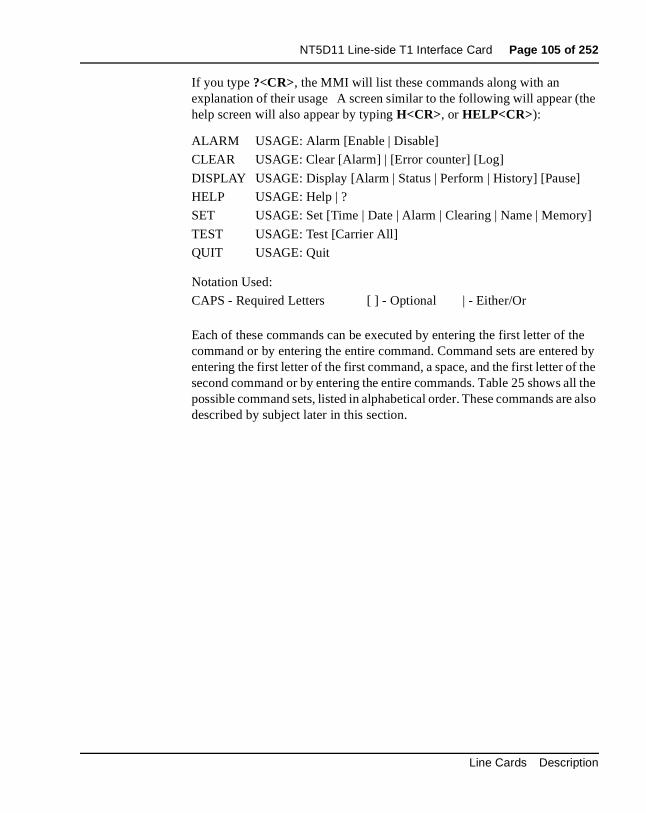
NT5D11 Line-side T1 Interface Card Page 105 of 252
the
the d by the ll the e also
]
If you type ?<CR>, the MMI will list these commands along with an explanation of their usage A screen similar to the following will appear (help screen will also appear by typing H<CR>, or HELP<CR>):
Each of these commands can be executed by entering the first letter of command or by entering the entire command. Command sets are entereentering the first letter of the first command, a space, and the first letter ofsecond command or by entering the entire commands. Table 25 shows apossible command sets, listed in alphabetical order. These commands ardescribed by subject later in this section.
ALARM USAGE: Alarm [Enable | Disable]
CLEAR USAGE: Clear [Alarm] | [Error counter] [Log]
DISPLAY USAGE: Display [Alarm | Status | Perform | History] [Pause]
HELP USAGE: Help | ?
SET USAGE: Set [Time | Date | Alarm | Clearing | Name | Memory
TEST USAGE: Test [Carrier All]
QUIT USAGE: Quit
Notation Used:
CAPS - Required Letters [ ] - Optional | - Either/Or
Line Cards Description
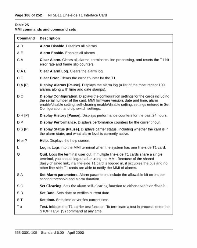
Page 106 of 252 NT5D11 Line-side T1 Interface Card
Table 25MMI commands and command sets
Command Description
A D Alarm Disable. Disables all alarms.
A E Alarm Enable. Enables all alarms.
C A Clear Alarm. Clears all alarms, terminates line processing, and resets the T1 bit error rate and frame slip counters.
C A L Clear Alarm Log. Clears the alarm log.
C E Clear Error. Clears the error counter for the T1.
D A [P] Display Alarms [Pause]. Displays the alarm log (a list of the most recent 100 alarms along with time and date stamps).
D C Display Configuration. Displays the configuration settings for the cards including the serial number of the card, MMI firmware version, date and time, alarm enable/disable setting, self-clearing enable/disable setting, settings entered in Set Configuration, and dip switch settings.
D H [P] Display History [Pause]. Displays performance counters for the past 24 hours.
D P Display Performance. Displays performance counters for the current hour.
D S [P] Display Status [Pause]. Displays carrier status, including whether the card is in the alarm state, and what alarm level is currently active.
H or ? Help. Displays the help screen.
L Login. Logs into the MMI terminal when the system has one line-side T1 card.
Q Quit. Logs the terminal user out. If multiple line-side T1 cards share a single terminal, you should logout after using the MMI. Because of the shared daisy-chained link, if a line-side T1 card is logged in, it occupies the bus and no other line-side T1 cards are able to notify the MMI of alarms.
S A Set Alarm parameters. Alarm parameters include the allowable bit errors per second threshold and alarm duration.
S C Set Clearing. Sets the alarm self-clearing function to either enable or disable.
S D Set Date. Sets date or verifies current date.
S T Set time. Sets time or verifies current time.
T x Test. Initiates the T1 carrier test function. To terminate a test in process, enter the STOP TEST (S) command at any time.
553-3001-105 Standard 6.00 April 2000
NT5D11 Line-side T1 Interface Card Page 107 of 252
n is
e MI ust
S D) nter the
an ls as
Configuring parametersThe MMI has been designed with default settings so that no configurationecessary. However, you may want to reconfigure it based on your ownenvironment.
Set TimeBefore you begin to configure your MMI, login to the system and enter thcurrent time. Do this by typing in the Set Time (S T) command set. The Mwill then display the time it has registered. You can enter a new time or jhit “Enter” to leave it unchanged. The time is entered in the “hh:mm:ss” military time format.
Set DateYou also need to set the current date. Do this by typing in the Set Date (command set. MMI will then display the date it has registered. You can ea new date or just hit “Enter” to leave it unchanged. The date is entered in“mm/dd/yy” format.
Alarm parametersThe Set Alarm (S A) command set establishes the parameters by whichalarm is activated, and its duration. There are three alarm activation levedescribed below:
• Alarm Level 0 (AL0) consists of activity with an error threshold belowthe AL1 setting. This is deemed to be a satisfactory condition and therefore no alarm will be activated.
Line Cards Description
Page 108 of 252 NT5D11 Line-side T1 Interface Card
re M in
this e
I
will
nd f and
the er 26.
nds it
s
nter
• Alarm Level 1 (AL1) consists of activity with an error threshold abovethe AL1 setting but below AL2 setting. This is deemed to be a minorunsatisfactory condition. In this situation, the external alarm hardwawill be activated by closing the normally open contact, the RED ALARLED on the faceplate will light, and an alarm message will be createdthe alarm log and the MMI terminal.
• Alarm Level 2 (AL2) consists of activity with an error threshold abovethe AL2 setting. This is deemed to be an unsatisfactory condition. In situation, the external alarm hardware will be activated by closing thnormally open contact, the RED ALARM LED on the faceplate will light, an alarm message will be created in the alarm log and the MMterminal, the line-side T1 card will enter line processing mode, and ayellow alarm message will be sent to the CPE/CSU. Line processing send the Meridian 1 either all “on-hook” or all “off-hook” signals, depending on the dip switch setting of the card.
When you use the Set Alarm command, you will be prompted to set the threshold level and duration period for alarm levels 1 and 2.
The threshold value indicates the number of bit errors detected per secothat is necessary to activate the alarm. The T1 link processes at a rate oapproximately 1.5 mb/s. The threshold value can be set between 3 and 9can be different for each alarm level. Any other value entered will causesoftware to display a “Parameter Invalid” message. The threshold numbthat you enter represents the respective power of 10 as shown in Table
Note: The error rate threshold for a level 2 alarm must be greater (asmaller power of 10) than for a level 1 alarm.
The duration value is set in seconds and can be set from 1 to 3,600 seco(1 hour). This duration value indicates how long the alarm will last. Low b
error rates (10-7 through 10-9) are restricted to longer durations since it take
more than one second to detect an alarm condition above 10-6 . Higher bit error rates are restricted to shorter durations because the MMI error coufills at 65,000 errors.
553-3001-105 Standard 6.00 April 2000
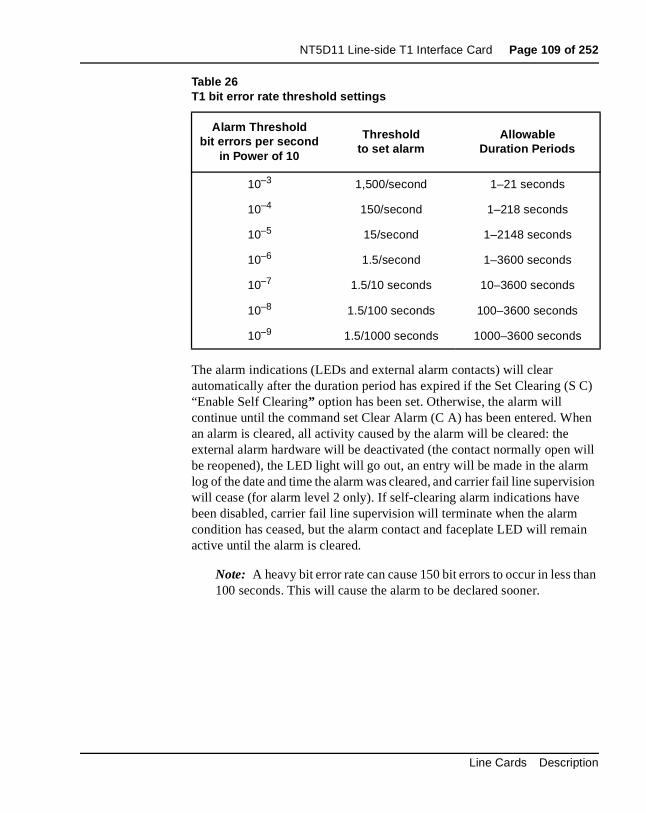
NT5D11 Line-side T1 Interface Card Page 109 of 252
C)
en
ill
sion
in
han
The alarm indications (LEDs and external alarm contacts) will clear automatically after the duration period has expired if the Set Clearing (S“Enable Self Clearing” option has been set. Otherwise, the alarm will continue until the command set Clear Alarm (C A) has been entered. Whan alarm is cleared, all activity caused by the alarm will be cleared: the external alarm hardware will be deactivated (the contact normally open wbe reopened), the LED light will go out, an entry will be made in the alarmlog of the date and time the alarm was cleared, and carrier fail line superviwill cease (for alarm level 2 only). If self-clearing alarm indications have been disabled, carrier fail line supervision will terminate when the alarmcondition has ceased, but the alarm contact and faceplate LED will remaactive until the alarm is cleared.
Note: A heavy bit error rate can cause 150 bit errors to occur in less t100 seconds. This will cause the alarm to be declared sooner.
Table 26T1 bit error rate threshold settings
Alarm Threshold bit errors per second
in Power of 10
Thresholdto set alarm
AllowableDuration Periods
10–3 1,500/second 1–21 seconds
10–4 150/second 1–218 seconds
10–5 15/second 1–2148 seconds
10–6 1.5/second 1–3600 seconds
10–7 1.5/10 seconds 10–3600 seconds
10–8 1.5/100 seconds 100–3600 seconds
10–9 1.5/1000 seconds 1000–3600 seconds
Line Cards Description
Page 110 of 252 NT5D11 Line-side T1 Interface Card
cts d.
150 eset ted, 50
the
by
ting m. If ame The
he d it the
e ger
ion
An alarm will not be automatically cleared until the system no longer detethe respective bit error threshold during the corresponding duration perio
For example, if an AL1 threshold of 6 (representing 10–6) and a duration period of 100 seconds is specified, an alarm will be activated if more than bit errors occur in any 100 second period (1.5 seconds X 100 seconds =150/100 seconds). As soon as the alarm is activated, the bit counter is rto 0. If the next 100 seconds pass, and less than 150 bit errors are detecthen the alarm will clear after the duration period. However, if more than 1bit errors are detected in the next 100 seconds, the alarm continues for designated duration period. The alarm will finally clear when the alarm condition is no longer detected for the designated duration period eitherself-clearing (if this function is enabled), or when the Clear Alarm (C A) command set is entered.
In addition to bit errors, the Set Alarm function sets parameters for detecframe slip errors by establishing a threshold necessary to activate an alarthe threshold value is exceeded, a level 2 alarm will be activated. The frslip threshold can be specified from 1 to 255 frame slips per time period. duration time period can be specified from 1 to 24 hours.
When entering the Set Alarm command set, the MMI will scroll through tpreviously described series of alarm options. These options are displayealong with their current value, and you can either enter a new value or henter to retain the current value. Table 27 outlines the options available inSet Alarm function.
Note: If the duration period is set too long, the line-side T1 card will bslow to return to service automatically even when the carrier is no lonexperiencing any errors. The Clear Alarm command will have to be entered manually to restore service promptly. To avoid this, the duratperiod should normally be set to 10 seconds.
553-3001-105 Standard 6.00 April 2000
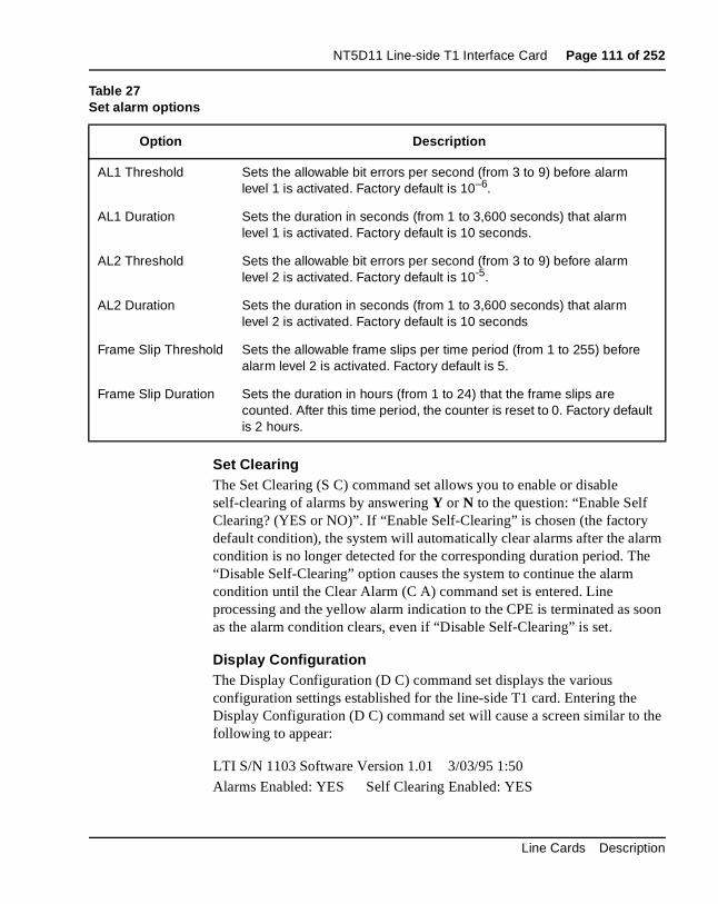
NT5D11 Line-side T1 Interface Card Page 111 of 252
rm e
oon
the
Set ClearingThe Set Clearing (S C) command set allows you to enable or disable self-clearing of alarms by answering Y or N to the question: “Enable Self Clearing? (YES or NO)”. If “Enable Self-Clearing” is chosen (the factory default condition), the system will automatically clear alarms after the alacondition is no longer detected for the corresponding duration period. Th“Disable Self-Clearing” option causes the system to continue the alarm condition until the Clear Alarm (C A) command set is entered. Line processing and the yellow alarm indication to the CPE is terminated as sas the alarm condition clears, even if “Disable Self-Clearing” is set.
Display ConfigurationThe Display Configuration (D C) command set displays the various configuration settings established for the line-side T1 card. Entering the Display Configuration (D C) command set will cause a screen similar to following to appear:
LTI S/N 1103 Software Version 1.01 3/03/95 1:50
Alarms Enabled: YES Self Clearing Enabled: YES
Table 27Set alarm options
Option Description
AL1 Threshold Sets the allowable bit errors per second (from 3 to 9) before alarm level 1 is activated. Factory default is 10–6.
AL1 Duration Sets the duration in seconds (from 1 to 3,600 seconds) that alarm level 1 is activated. Factory default is 10 seconds.
AL2 Threshold Sets the allowable bit errors per second (from 3 to 9) before alarm level 2 is activated. Factory default is 10-5.
AL2 Duration Sets the duration in seconds (from 1 to 3,600 seconds) that alarm level 2 is activated. Factory default is 10 seconds
Frame Slip Threshold Sets the allowable frame slips per time period (from 1 to 255) before alarm level 2 is activated. Factory default is 5.
Frame Slip Duration Sets the duration in hours (from 1 to 24) that the frame slips are counted. After this time period, the counter is reset to 0. Factory default is 2 hours.
Line Cards Description
Page 112 of 252 NT5D11 Line-side T1 Interface Card
10
1
ns
in
e,
ive e T1 is red, if, e
Alarm Level 1 threshold value: E-7 Threshold duration (in seconds):
Alarm Level 2 threshold value: E-5 Threshold duration (in seconds):
Frame slips alarm level threshold: 5 Threshold duration (in hours): 2
Current dip switch S1 settings (S1..S8) On Off Off On Off Off Off On
Current dip switch S2 settings (S1..S8) On Off On Off Off Off On Off
Alarm operation and reportingThe MMI monitors the T1 link according to the parameters established through the Set Alarm command set for the following conditions:
• Excessive bit error rate
• Frame slip errors
• Out of frame condition
• Loss of signal condition
• Blue alarm (AIS) condition
Descriptions of the excessive bit error rate and frame slip errors conditiocan be found in “Configuring parameters” on page 107. Bit errors may activate either a level 1 or level 2 alarm. The remaining conditions, whendetected, will always cause the system to activate a level 2 alarm.
An out of frame condition will be declared if two out of four frame bits are error. If this condition occurs, the hardware will immediately attempt to reframe. During the reframe time, the T1 link will be declared out of framand silence will be sent on all receive timeslots.
A loss of signal condition is declared if a full frame (192 bits) of consecutzeros has been detected at the receive inputs. If this condition occurs, thlink will automatically attempt to resynchronize with the distant end. If thcondition occurs for more than two seconds, a level 2 alarm will be declaand silence will be sent on all receive timeslots. The alarm will be clearedafter two seconds, neither a loss of signal, out of frame condition, nor blualarm condition occurs.
553-3001-105 Standard 6.00 April 2000
NT5D11 Line-side T1 Interface Card Page 113 of 252
This IS and fter rm
. s
e ill
ble d set
ally n sing e n
If a repeating device loses signal, it will immediately begin sending an unframed all ones signal to the distant end to indicate an alarm condition. condition is called a blue alarm, or an alarm indication signal (AIS). If an Ais detected for more than two seconds, a level 2 alarm will be declared, silence will be sent on all receive timeslots. The alarm will be cleared if, atwo seconds, neither a loss of signal, out of frame condition, nor blue alacondition occurs.
Alarm DisableThe Alarm Disable (A D) command disables the external alarm contactsWhen this command is typed in the MMI will display the message “AlarmDisabled” and the MAINT LED will light. In this mode, no yellow alarms arsent and the line-side T1 card will not enter line processing mode. Alarmmessages will still be to be sent on the MMI terminal and the LED light wstill continue to indicate alarm conditions.
Alarm EnableThe Alarm Enable (A E) command set does the reverse of the Alarm Disacommand set. It enables the external alarm contacts. When this commanis typed in, the MMI will display the message “Alarms Enabled.” In this mode, yellow alarms can be sent and the line-side T1 card can enter lineprocessing mode.
Clear Alarm The Clear Alarm (C A) command set will clear all activity initiated by an alarm: the external alarm hardware will be deactivated (the contact normopen will be reopened), the LED light will go out, an entry will be made ithe alarm log of the date and time the alarm was cleared, and line proceswill cease (for alarm level 2 only). When this command set is typed in, thMMI will display the message “Alarm acknowledged.” If the alarm conditiostill exists, the alarm will be declared again.
Line Cards Description
Page 114 of 252 NT5D11 Line-side T1 Interface Card
can n
tering
g
Display AlarmsA detailed report of the most recent 100 alarms with time and date stampsbe displayed by entering the Display Alarms (D A) command set into theMMI. Entering the Display Alarms (D A) command set will cause a screesimilar to the following to appear:
The Pause command can be used to display a full screen at a time by enD A P.
Clear Alarm LogYou can clear all entries in the alarm log by typing in the Clear Alarm Lo(C A L) command set.
Alarm Log
3/03/95 1:48 Yellow alarm on T1 carrier
3/03/95 1:50 Initialized Memory
3/03/95 2:33 T1 carrier level 1 alarm
3/03/95 3:47 T1 carrier level 2 alarm
3/03/95 4:43 T1 carrier performance within thresholds
3/03/95 15:01 Log Cleared
553-3001-105 Standard 6.00 April 2000
NT5D11 Line-side T1 Interface Card Page 115 of 252
tion orts will
and ing
r
a
ored rely or
k,
k,
k
Display StatusThe Display Status (D S) command set displays the current alarm condiof the T1 link as well as the on-hook or off-hook status of each of the 24 pof the line-side T1 card. Entering the Display Status (D S) command set cause a screen similar to the following to appear:
Performance counters and reportingThe MMI monitors the performance of the T1 link according to several performance criteria including errored, bursty, unavailable, loss of frame frame slip seconds. It registers the performance of these criteria by readtheir status every second and counting their results. These counts are accumulated for an hour, at which time they are reset to 0. Previous houcount results are maintained for each hours for the previous 24 hours.
The performance criteria for which these counts are maintained are as follows:
• Errored seconds—one or more CRC-6 errors, or one or more out offrame errors in a second
• Bursty seconds—more than one and less than 320 CRC-6 errors in second
• Unavailable seconds—unavailable state starts with 10 consecutive severely errored seconds and ends with 10 consecutive severely errseconds (excluding the final 10 non-severely errored seconds). Seveerrored seconds are defined as more than 320 CRC-6 errors, or onemore out of frames in a second
LTI S/N Software Version 1.01 3/03/95 1:50
In alarm state: NO
T1 link at alarm level 0
Port 0 off hook, Port 1 on hook, Port 2 on hook, Port 3 on hook,
Port 4 on hook, Port 5 on hook, Port 6 off hook, Port 7 off hook,
Port 8 off hook, Port 9 on hook, Port 10 on hook, Port 11 on hook,
Port 12 off hook, Port 13 on hook, Port 14 on hook, Port 15 on hoo
Port 16 on hook, Port 17 on hook, Port 18 off hook, Port 19 off hoo
Port 20 off hook, Port 21 on hook, Port 22 on hook, Port 23 on hoo
Line Cards Description
Page 116 of 252 NT5D11 Line-side T1 Interface Card
the
ill
or have
e nto
will
the nters log. was
ter
• Loss of frame seconds—loss of frame or loss of signal for three consecutive seconds
• Framer slip seconds—one ore more frame slips in a second
The MMI also maintains an overall error counter that is just a sum of all errors counted for the five performance criteria listed above. The error counter can only be cleared by entering the “Clear Error” command. It wstop counting at 65,000. The error counter provides an easy method to determine if an alarm condition has been corrected. Simply clear the errcounter, wait a few minutes, and display performance to see if any errors occurred since the counter was cleared.
Reports on these performance counters can be displayed by entering thDisplay Performance (D P) or the Display History (D H) command sets ithe MMI.
Display PerformanceEntering the Display Performance (D P) command set will display performance counters for the past hour. A screen similar to the following appear:
Each column, except the error counter, indicates the number of errors incurrent hour and is reset to zero every hour on the hour. When these couare reset to zero, the performance counter values are put into the historyThe error counter indicates the number of errors since the error counter cleared.
LTI T1 Interface Performance Log
3/03/95 1:37
Data for the past 37 Minutes
Errored Bursty Unavailable Loss Frame Frame Slip Error
Seconds Seconds Seconds Seconds Seconds Coun
2263 0 2263 2263 352 321
553-3001-105 Standard 6.00 April 2000
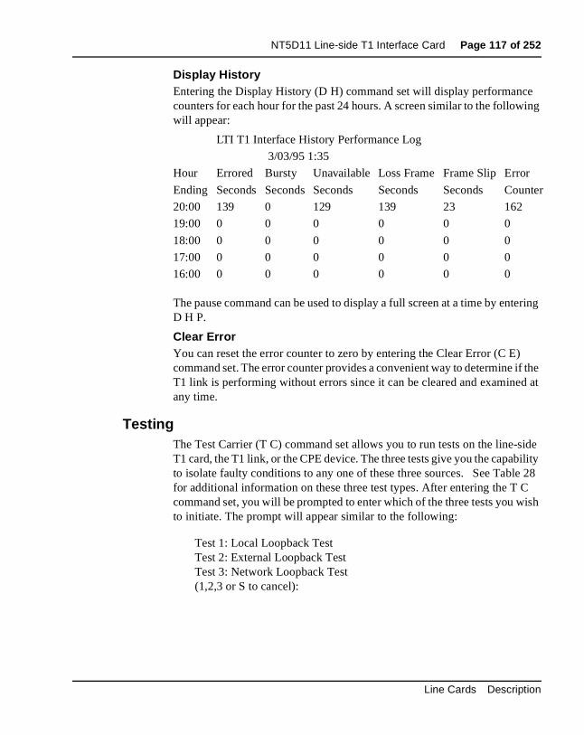
NT5D11 Line-side T1 Interface Card Page 117 of 252
e ing
ering
if the d at
ide ility
e 28 ish
unter
Display HistoryEntering the Display History (D H) command set will display performanccounters for each hour for the past 24 hours. A screen similar to the followwill appear:
The pause command can be used to display a full screen at a time by entD H P.
Clear ErrorYou can reset the error counter to zero by entering the Clear Error (C E)command set. The error counter provides a convenient way to determine T1 link is performing without errors since it can be cleared and examineany time.
TestingThe Test Carrier (T C) command set allows you to run tests on the line-sT1 card, the T1 link, or the CPE device. The three tests give you the capabto isolate faulty conditions to any one of these three sources. See Tablfor additional information on these three test types. After entering the T Ccommand set, you will be prompted to enter which of the three tests you wto initiate. The prompt will appear similar to the following:
Test 1: Local Loopback TestTest 2: External Loopback Test Test 3: Network Loopback Test(1,2,3 or S to cancel):
LTI T1 Interface History Performance Log
3/03/95 1:35
Hour Errored Bursty Unavailable Loss Frame Frame Slip Error
Ending Seconds Seconds Seconds Seconds Seconds Co
20:00 139 0 129 139 23 162
19:00 0 0 0 0 0 0
18:00 0 0 0 0 0 0
17:00 0 0 0 0 0 0
16:00 0 0 0 0 0 0
Line Cards Description
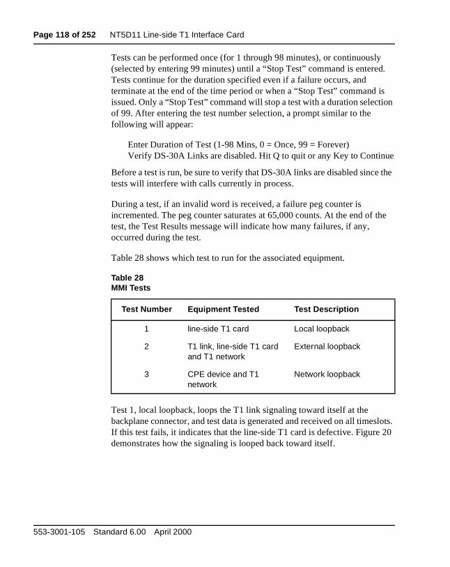
Page 118 of 252 NT5D11 Line-side T1 Interface Card
y d.
is tion
e
the
the
slots. 20
Tests can be performed once (for 1 through 98 minutes), or continuousl(selected by entering 99 minutes) until a “Stop Test” command is entereTests continue for the duration specified even if a failure occurs, and terminate at the end of the time period or when a “Stop Test” command issued. Only a “Stop Test” command will stop a test with a duration selecof 99. After entering the test number selection, a prompt similar to the following will appear:
Enter Duration of Test (1-98 Mins, 0 = Once, 99 = Forever) Verify DS-30A Links are disabled. Hit Q to quit or any Key to Continu
Before a test is run, be sure to verify that DS-30A links are disabled sincetests will interfere with calls currently in process.
During a test, if an invalid word is received, a failure peg counter is incremented. The peg counter saturates at 65,000 counts. At the end oftest, the Test Results message will indicate how many failures, if any, occurred during the test.
Table 28 shows which test to run for the associated equipment.
Test 1, local loopback, loops the T1 link signaling toward itself at the backplane connector, and test data is generated and received on all timeIf this test fails, it indicates that the line-side T1 card is defective. Figuredemonstrates how the signaling is looped back toward itself.
Table 28MMI Tests
Test Number Equipment Tested Test Description
1 line-side T1 card Local loopback
2 T1 link, line-side T1 card and T1 network
External loopback
3 CPE device and T1 network
Network loopback
553-3001-105 Standard 6.00 April 2000
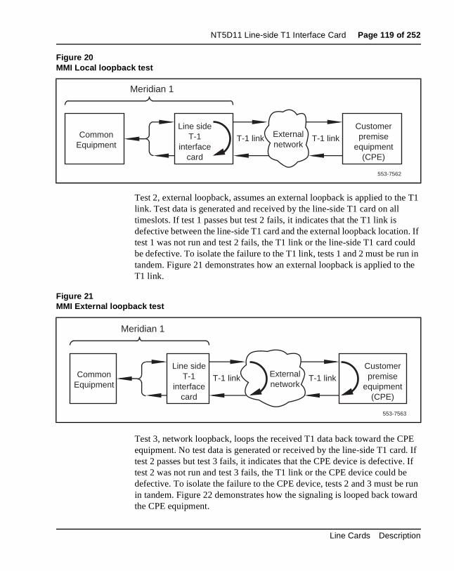
NT5D11 Line-side T1 Interface Card Page 119 of 252
e T1
n. If uld n in the
PE d. If . If
e run ard
Test 2, external loopback, assumes an external loopback is applied to thlink. Test data is generated and received by the line-side T1 card on all timeslots. If test 1 passes but test 2 fails, it indicates that the T1 link is defective between the line-side T1 card and the external loopback locatiotest 1 was not run and test 2 fails, the T1 link or the line-side T1 card cobe defective. To isolate the failure to the T1 link, tests 1 and 2 must be rutandem. Figure 21 demonstrates how an external loopback is applied toT1 link.
Test 3, network loopback, loops the received T1 data back toward the Cequipment. No test data is generated or received by the line-side T1 cartest 2 passes but test 3 fails, it indicates that the CPE device is defectivetest 2 was not run and test 3 fails, the T1 link or the CPE device could bdefective. To isolate the failure to the CPE device, tests 2 and 3 must bein tandem. Figure 22 demonstrates how the signaling is looped back towthe CPE equipment.
Figure 20MMI Local loopback test
Figure 21MMI External loopback test
T-1 linkLine side
T-1 interface
card
Customer premise
equipment (CPE)
Common Equipment
Meridian 1
External network
T-1 link
553-7562
T-1 linkLine side
T-1 interface
card
Customer premise
equipment (CPE)
Common Equipment
Meridian 1
External network
T-1 link
553-7563
Line Cards Description
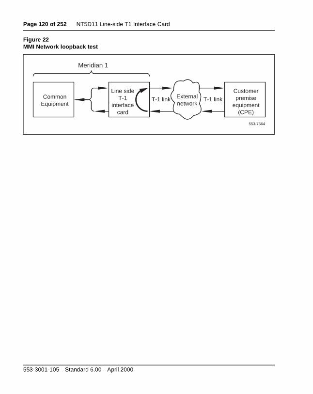
Page 120 of 252 NT5D11 Line-side T1 Interface Card
Figure 22MMI Network loopback test
T-1 linkLine side
T-1 interface
card
Customer premise
equipment (CPE)
Common Equipment
Meridian 1
External network
T-1 link
553-7564
553-3001-105 Standard 6.00 April 2000
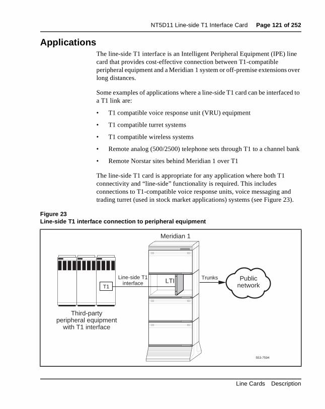
NT5D11 Line-side T1 Interface Card Page 121 of 252
e
over
ed to
bank
d ).
ApplicationsThe line-side T1 interface is an Intelligent Peripheral Equipment (IPE) lincard that provides cost-effective connection between T1-compatible peripheral equipment and a Meridian 1 system or off-premise extensions long distances.
Some examples of applications where a line-side T1 card can be interfaca T1 link are:
• T1 compatible voice response unit (VRU) equipment
• T1 compatible turret systems
• T1 compatible wireless systems
• Remote analog (500/2500) telephone sets through T1 to a channel
• Remote Norstar sites behind Meridian 1 over T1
The line-side T1 card is appropriate for any application where both T1 connectivity and “line-side” functionality is required. This includes connections to T1-compatible voice response units, voice messaging antrading turret (used in stock market applications) systems (see Figure 23
Figure 23Line-side T1 interface connection to peripheral equipment
553-7594
Line-side T1interface LTI
Meridian 1
Public networkT1
Trunks
Third-partyperipheral equipment
with T1 interface
Line Cards Description
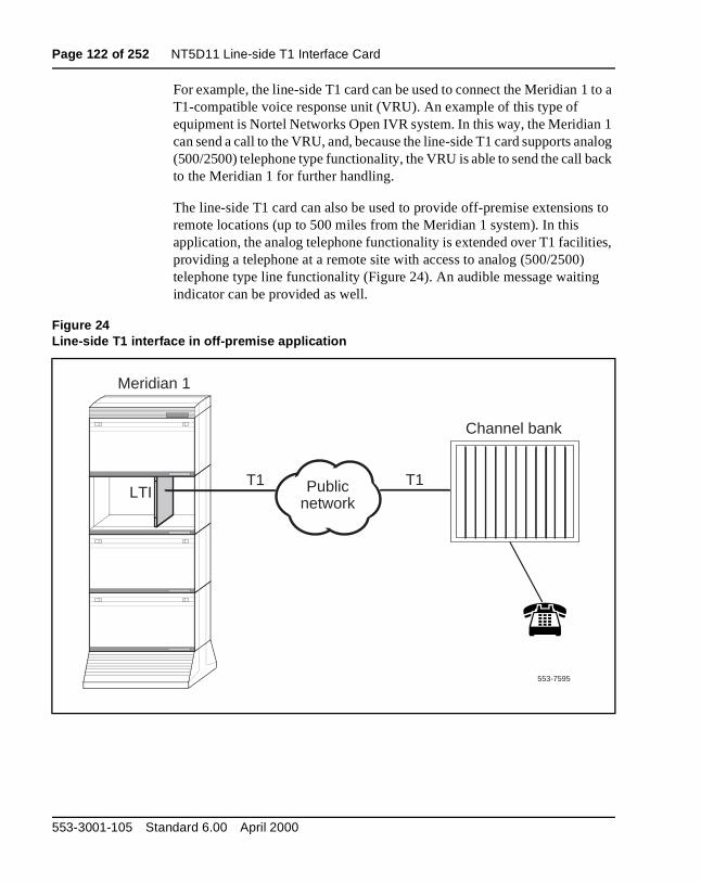
Page 122 of 252 NT5D11 Line-side T1 Interface Card
to a
1 nalog ack
s to
ies,
For example, the line-side T1 card can be used to connect the Meridian 1T1-compatible voice response unit (VRU). An example of this type of equipment is Nortel Networks Open IVR system. In this way, the Meridiancan send a call to the VRU, and, because the line-side T1 card supports a(500/2500) telephone type functionality, the VRU is able to send the call bto the Meridian 1 for further handling.
The line-side T1 card can also be used to provide off-premise extensionremote locations (up to 500 miles from the Meridian 1 system). In this application, the analog telephone functionality is extended over T1 facilitproviding a telephone at a remote site with access to analog (500/2500)telephone type line functionality (Figure 24). An audible message waitingindicator can be provided as well.
Figure 24Line-side T1 interface in off-premise application
553-7595
T1 T1
Channel bank
LTI
Meridian 1
Public network
553-3001-105 Standard 6.00 April 2000
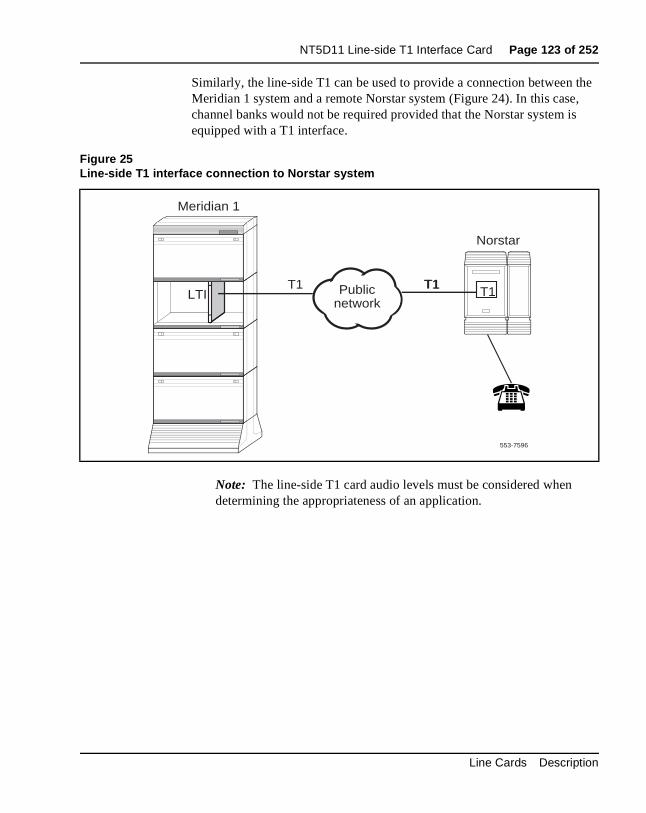
NT5D11 Line-side T1 Interface Card Page 123 of 252
the ,
s
Similarly, the line-side T1 can be used to provide a connection betweenMeridian 1 system and a remote Norstar system (Figure 24). In this casechannel banks would not be required provided that the Norstar system iequipped with a T1 interface.
Note: The line-side T1 card audio levels must be considered when determining the appropriateness of an application.
Figure 25Line-side T1 interface connection to Norstar system
553-7596
T1
Norstar
T1 T1LTI
Meridian 1
Public network
T1
Line Cards Description
Page 124 of 252 NT5D11 Line-side T1 Interface Card
553-3001-105 Standard 6.00 April 2000
Page 125 of 252
184
NT5D33 and NTRB34 Line-sideE1 Interface Cards
Content listThe following are the topics in this section:
• Introduction 126
• Physical description 126
• Card connections 127
• Faceplate 127
• Functional description 131
• Overview 131
• Card interfaces 133
• Electrical specifications 135
• E1 channel specifications 136
• Power requirements 136
• Foreign and surge voltage protections 136
• Installation and Configuration 137
• Dip switch settings 138
• Installation 144
• Cabling the line-side E1 card (LEI) 147
• Terminal configuration 153
• Man-Machine E1 maintenance interface software 156
Line Cards Description
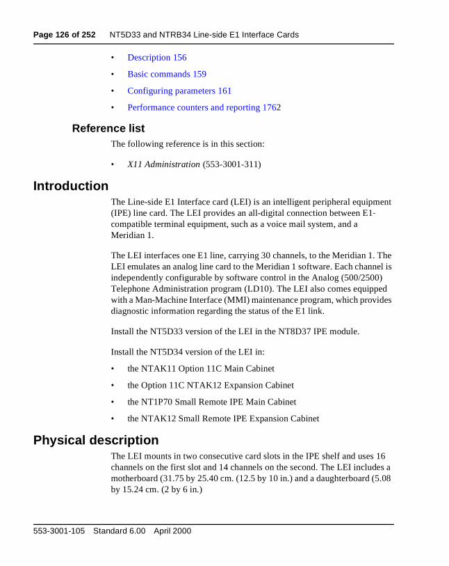
Page 126 of 252 NT5D33 and NTRB34 Line-side E1 Interface Cards
nt
he el is d es
16 es a 5.08
• Description 156
• Basic commands 159
• Configuring parameters 161
• Performance counters and reporting 1762
Reference listThe following reference is in this section:
• X11 Administration (553-3001-311)
IntroductionThe Line-side E1 Interface card (LEI) is an intelligent peripheral equipme(IPE) line card. The LEI provides an all-digital connection between E1 compatible terminal equipment, such as a voice mail system, and a Meridian 1.
The LEI interfaces one E1 line, carrying 30 channels, to the Meridian 1. TLEI emulates an analog line card to the Meridian 1 software. Each channindependently configurable by software control in the Analog (500/2500)Telephone Administration program (LD10). The LEI also comes equippewith a Man-Machine Interface (MMI) maintenance program, which providdiagnostic information regarding the status of the E1 link.
Install the NT5D33 version of the LEI in the NT8D37 IPE module.
Install the NT5D34 version of the LEI in:
• the NTAK11 Option 11C Main Cabinet
• the Option 11C NTAK12 Expansion Cabinet
• the NT1P70 Small Remote IPE Main Cabinet
• the NTAK12 Small Remote IPE Expansion Cabinet
Physical descriptionThe LEI mounts in two consecutive card slots in the IPE shelf and uses channels on the first slot and 14 channels on the second. The LEI includmotherboard (31.75 by 25.40 cm. (12.5 by 10 in.) and a daughterboard (by 15.24 cm. (2 by 6 in.)
553-3001-105 Standard 6.00 April 2000
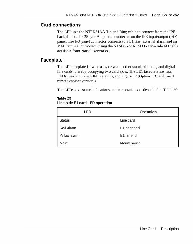
NT5D33 and NTRB34 Line-side E1 Interface Cards Page 127 of 252
E O) an
le
ital ll
e 29:
Card connectionsThe LEI uses the NT8D81AA Tip and Ring cable to connect from the IPbackplane to the 25-pair Amphenol connector on the IPE input/output (I/panel. The I/O panel connector connects to a E1 line, external alarm andMMI terminal or modem, using the NT5D35 or NT5D36 Line-side I/O cabavailable from Nortel Networks.
FaceplateThe LEI faceplate is twice as wide as the other standard analog and digline cards, thereby occupying two card slots. The LE1 faceplate has fourLEDs. See Figure 26 (IPE version), and Figure 27 (Option 11C and smaremote cabinet version.)
The LEDs give status indications on the operations as described in Tabl
Table 29Line-side E1 card LED operation
LED Operation
Status Line card
Red alarm E1 near end
Yellow alarm E1 far end
Maint Maintenance
Line Cards Description

Page 128 of 252 NT5D33 and NTRB34 Line-side E1 Interface Cards
Figure 26NT5D33AB Line-side E1 card—faceplate
553-3001-105 Standard 6.00 April 2000
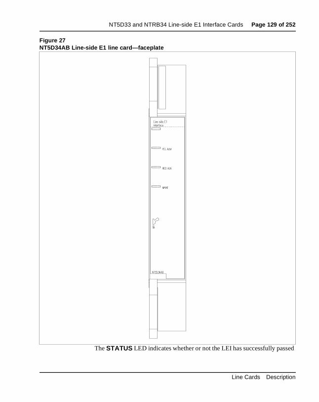
NT5D33 and NTRB34 Line-side E1 Interface Cards Page 129 of 252
ed
Figure 27NT5D34AB Line-side E1 line card—faceplate
The STATUS LED indicates whether or not the LEI has successfully pass
Line Cards Description
Page 130 of 252 NT5D33 and NTRB34 Line-side E1 Interface Cards
is . If ains
ED any ard
th th e card
ded
m larm
r
lit
its self test, and therefore, whether or not it is functional. When the cardinstalled, this LED remains lit for two to five seconds as the self-test runsthe self-test completes successfully, the LED flashes three times and remlit until the card is configured and enabled in software, at which time the Lgoes out. If the LED does not follow the pattern described or operates inother manner (such as continually flashing or remaining weakly lit), the cshould be replaced.
Note: The STATUS LED indicates the enabled/disabled status of bocard slots of the LEI simultaneously. To properly enable the card, bothe motherboard and the daughterboard slots must be enabled. TheSTATUS LED will turn out as soon as either one of the LEI slots havbeen enabled. No LED operation will be observed when the second slot is enabled. To properly disable the card, both card slots must bedisabled. The LED will not turn on until both card slots have been disabled.
The RED ALARM LED indicates whether or not the LEI has detected analarm condition from the E1 link. Alarm conditions include, but are not limited to, such conditions as not receiving a signal, the signal has exceebit error thresholds or frame slip thresholds. See “Man-Machine E1 maintenance interface software” on page 156 for information on E1 link maintenance.
If one of these alarm conditions is detected, this LED will light. Yellow alarindication is sent to the far end as long as the near end remains in a red acondition. Depending on how the Man Machine Interface (MMI) is configured, this LED will remain lit until one the following actions occur:
• If the “Self-Clearing” function is enabled in the MMI, the LED will cleathe alarm when the alarm condition is no longer detected (this is thefactory default configuration).
• If the “Self-Clearing” function has not been enabled or it has been subsequently disabled in the MMI, the LED alarm indication will stay until the command “Clear Alarm” has been typed in the MMI, even though the carrier automatically returned to service when the alarm condition was no longer detected.
553-3001-105 Standard 6.00 April 2000
NT5D33 and NTRB34 Line-side E1 Interface Cards Page 131 of 252
red
MMI. run d it
e ges.
nt en
and
be nes k
The YELLOW ALARM LED indicates that the LEI has detected a yellowalarm signal from the terminal equipment side of the E1 link. See “Man-Machine E1 maintenance interface software” on page 156 for information on E1 link maintenance. If the terminal equipment detects a alarm condition (including, but not limited to, such conditions as not receiving a signal, the signal exceeds bit-error thresholds or frame-slip thresholds), it may send a yellow alarm signal to the LEI, depending on whether or not your terminal equipment supports this feature. If a yellowalarm signal is detected, this LED will light.
The MAINT LED indicates whether or not the LEI is fully operational because of certain maintenance commands that are issued through the See “Man-Machine E1 maintenance interface software” on page 156 forinformation on E1 link maintenance. If the card detects that tests are beingor that alarms have been disabled through the MMI, this LED will light anwill remain lit until these conditions are no longer detected, at which timewill turn off.
Functional descriptionFigure 28 shows a block diagram of the major functions contained on thline-side E1 card. Each of these functions is described on the following pa
OverviewThe Line-side E1 Interface card (LEI) is an intelligent peripheral equipme(IPE) line card that provides a cost-effective, all-digital connection betweE1 compatible terminal equipment (such as voice mail systems, voice response units, trading turrets, etc.) and a Meridian 1 system. In this application, the terminal equipment can be assured access to analog (500/2500) telephone line functionality such as hook flash, SPRE codesringback tones generated from the Meridian 1. The LEI supports line supervision features such as loop and ground start protocols. It may alsoused in an off-premise arrangement whereby analog (500/2500) telephoare extended over twisted pair or coaxial E1 with the use of channel banequipment.
Line Cards Description
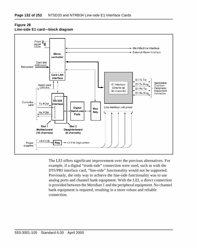
Page 132 of 252 NT5D33 and NTRB34 Line-side E1 Interface Cards
or
tion nnel
The LEI offers significant improvement over the previous alternatives. Fexample, if a digital “trunk-side” connection were used, such as with theDTI/PRI interface card, “line-side” functionality would not be supported. Previously, the only way to achieve the line-side functionality was to useanalog ports and channel bank equipment. With the LEI, a direct connecis provided between the Meridian 1 and the peripheral equipment. No chabank equipment is required, resulting in a more robust and reliable connection.
Figure 28Line-side E1 card—block diagram
553-3001-105 Standard 6.00 April 2000
NT5D33 and NTRB34 Line-side E1 Interface Cards Page 133 of 252
g, o be
lic
rd
2
lly he s it
ges
When used for connecting to third-party applications equipment, the LEIoffers a number of benefits. It is a more cost-effective alternative for connection because it eliminates the need for expensive channel bank equipment. In addition, the Line-side E1 supports powerful E1 monitorinand diagnostic capability. Overall costs for customer applications may alsreduced because the E1-compatible peripheral equipment is often moreattractively priced than the analog-port alternatives.
The LEI is compatible with all IPE-based systems and with standard pubor private CEPT-type carrier facilities. It supports CRC-4- or FAS only framing formats as well as AMI or HDB3 coding. Because it uses standaPCM in standard E1 timeslots, existing E1 test equipment remains compatible for diagnostic and fault isolation purposes. A/B Bit signaling may be customized according to the user’s system, including the Australian Psignaling scheme.
Card interfacesThe LEI passes voice and signaling data over DS-30X loops through theDS-30X Interface circuits and maintenance data over the card LAN link.
E1 interface circuitThe LEI contains one E1 line-interface circuit which provides 30 individuaconfigurable voice interfaces to one E1 link in 30 different time slots. Tcircuit demultiplexes the 2.56 Mbps DS-30X transmit signaling bitstreamfrom the DS-30X network loop and converts it into 2.048 mHz E1 transmsignaling bitstreams onto the E1 link. It also does the opposite, receivingreceive signaling bitstreams from the E1 link and transmitting receive signaling bitstreams onto the DS-30X network loop.
The E1 interface circuit provides the following:
• An industry standard CEPT (0 to 655 feet) interface
• DS-30X signaling protocol into FXO A- and B-channel-associated signaling protocol
• Switch-selectable transmission and reception of E1 signaling messaover an E1 link in either loop or ground start mode
• Switch-selectable call processing between the Australian P2, North American Standard, or other user-configurable schemes
Line Cards Description
Page 134 of 252 NT5D33 and NTRB34 Line-side E1 Interface Cards
ise,
rk
on
the ler
ons
Signaling and controlThe LEI also contains signaling and control circuits that establish, supervand take down call connections. These circuits work with the system controller to operate the E1 line interface circuit during calls. The circuitsreceive outgoing call signaling messages from the controller and return incoming call status information to the controller over the DS-30X netwoloop.
Card control functionsControl functions are provided by a microcontroller and a card LAN link the LEI. A sanity timer is provided to automatically reset the card if the microcontroller stops functioning for any reason.
MicrocontrollersThe LEI contains a microcontroller that controls the internal operation of card and the serial card LAN link to the controller card. The microcontrolcontrols the following:
• reporting to the CE CP via the card LAN link
— card identification (card type, vintage, serial number)
— firmware version
— self-test results
— programmed unit parameter status
• receipt and implementation of card configuration
— control of the E1 line interface
— enabling/disabling of individual units or entire card
— programming of loop interface control circuits for administration of channel operation
— maintenance diagnostics
• interface with the line card circuit
— converts on/off-hook, and ringer control messages from the DS-30X loop into A/B bit manipulations for each time slot in the E1 data stream, using channel associated signaling.
• the front panel LED when the card is enabled or disabled by instructifrom the NT8D01 controller card.
553-3001-105 Standard 6.00 April 2000
NT5D33 and NTRB34 Line-side E1 Interface Cards Page 135 of 252
ard
the
e eset
ed
I/O ugh
on
lists
Card LAN interfaceMaintenance data is exchanged with the Common Equipment CP over adedicated asynchronous serial network called the Card LAN link. The CLAN link is described in “Card LAN link” on page 20.
Sanity TimerThe LEI also contains a sanity timer that resets the microcontroller in theevent of a loss of program control. If the timer is not properly serviced by microcontroller, it times out and causes the microcontroller to be hardware-reset. If the microcontroller loses control and fails to service thsanity timer at least once per second, the sanity timer will automatically rthe microcontroller, restoring program control.
Man-Machine Interface (MMI)The LEI provides an optional Man-Machine Interface that is primarily usfor E1 link performance monitoring and problem diagnosis. The MMI provides alarm notification, E1 link performance reporting, and fault isolation testing. The interface is accessed through connections from thepanel to a terminal or modem. Multiple cards (up to 64) can be served throone MMI terminal or modem by linking the LEIs via daisy chain.
The MMI is an optional feature, since all E1 configuration settings are performed through dip switch settings or preconfigured factory default settings. Available MMI commands, and their complete functionality, arediscussed in-depth in “Man-Machine E1 maintenance interface software”page 156.
Electrical specificationsTable 30 provides a technical summary of the E1 line interface. Table 31 the maximum power consumed by the card.
Line Cards Description
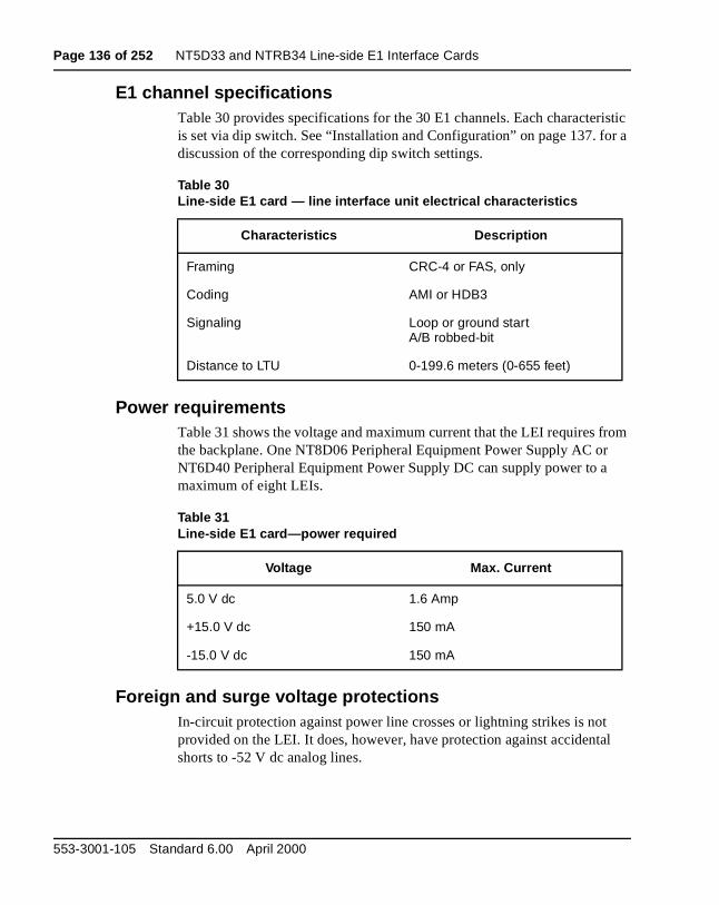
Page 136 of 252 NT5D33 and NTRB34 Line-side E1 Interface Cards
istic r a
rom
l
E1 channel specificationsTable 30 provides specifications for the 30 E1 channels. Each characteris set via dip switch. See “Installation and Configuration” on page 137. fodiscussion of the corresponding dip switch settings.
Power requirementsTable 31 shows the voltage and maximum current that the LEI requires fthe backplane. One NT8D06 Peripheral Equipment Power Supply AC orNT6D40 Peripheral Equipment Power Supply DC can supply power to amaximum of eight LEIs.
Foreign and surge voltage protectionsIn-circuit protection against power line crosses or lightning strikes is not provided on the LEI. It does, however, have protection against accidentashorts to -52 V dc analog lines.
Table 30Line-side E1 card — line interface unit electrical characteristics
Characteristics Description
Framing CRC-4 or FAS, only
Coding AMI or HDB3
Signaling Loop or ground startA/B robbed-bit
Distance to LTU 0-199.6 meters (0-655 feet)
Table 31Line-side E1 card—power required
Voltage Max. Current
5.0 V dc 1.6 Amp
+15.0 V dc 150 mA
-15.0 V dc 150 mA
553-3001-105 Standard 6.00 April 2000
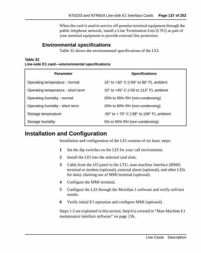
NT5D33 and NTRB34 Line-side E1 Interface Cards Page 137 of 252
the f
Is
t
E1
When the card is used to service off-premise terminal equipment throughpublic telephone network, install a Line Termination Unit (LTU) as part oyour terminal equipment to provide external line protection.
Environmental specificationsTable 32 shows the environmental specifications of the LEI.
Installation and ConfigurationInstallation and configuration of the LEI consists of six basic steps:
1 Set the dip switches on the LEI for your call environment.
2 Install the LEI into the selected card slots.
3 Cable from the I/O panel to the LTU, man-machine interface (MMI) terminal or modem (optional), external alarm (optional), and other LEfor daisy chaining use of MMI terminal (optional).
4 Configure the MMI terminal.
5 Configure the LEI through the Meridian 1 software and verify self-tesresults.
6 Verify initial E1 operation and configure MMI (optional).
Steps 1-5 are explained in this section. Step 6 is covered in “Man-Machinemaintenance interface software” on page 156.
Table 32Line-side E1 card—environmental specifications
Parameter Specifications
Operating temperature - normal 15° to +30° C (+59° to 86° F), ambient
Operating temperature - short term 10° to +45° C (+50 to 113° F), ambient
Operating humidity - normal 20% to 55% RH (non-condensing)
Operating humidity - short term 20% to 80% RH (non condensing)
Storage temperature -50° to + 70° C (-58° to 158° F), ambient
Storage humidity 5% to 95% RH (non-condensing)
Line Cards Description
Page 138 of 252 NT5D33 and NTRB34 Line-side E1 Interface Cards
er es, ht s for
hes
or
Dip switch settingsBegin your installation and configuration of the LEI by selecting the propdip switch settings for your environment. The LEI contains two dip switcheach containing eight switch positions. They are located in the upper rigcorner of the motherboard circuit card as shown in Figure 29. The settingthese switches are shown in Tables 33 through 36.
When the line-side E1 card is oriented as shown in Figure 29, the dip switcare ON when they are up, and OFF when they are down. The dip switchsettings configure your card for the following parameters:
MMI port speed selectionThis dip switch setting selects the appropriate baud rate for the terminalmodem (if any) that is connected to your MMI.
553-3001-105 Standard 6.00 April 2000
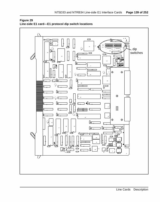
NT5D33 and NTRB34 Line-side E1 Interface Cards Page 139 of 252
Figure 29Line-side E1 card—E1 protocol dip switch locations
dipswitches
Line Cards Description
Page 140 of 252 NT5D33 and NTRB34 Line-side E1 Interface Cards
g pe
d. The e;
e of
ipheral
be
r he
ither
Line Supervisory Signaling protocolThe LEI is capable of supporting loop start or ground start call processinmodes. Make your selection for this dip switch position based on what tyof line signaling your Customer Premise Equipment (CPE) supports.
Address of LEI to the MMIThe address of the LEI to the MMI is made up of two components:
• the address of the card within the shelf
• the address of the shelf in which the card resides.
These two addresses are combined to create a unique address for the carMMI reads the address of the card within the shelf from the card firmwarthe address of the shelf must be set by this dip switch.
The shelf address dip switch can be from 0-15, 16 being the maximum number of Line-side E1 IPE shelves (a maximum of 64 LEI cards) capabldaisy chaining to a single MMI terminal. For clarity and ease, it is recommended that this address be set the same as the address of the percontroller identifier in overlay 97 for type: XPE. However, this is not mandatory, and, since the dip switch is limited to 16, this will not alwayspossible.
E1 framingThe LEI is capable of interfacing with LTU equipment either in CRC-4 orFAS only framing mode. Make your selection for this dip switch positionbased on what type of framing your LTU equipment supports.
E1 CodingThe LEI is capable of interfacing with LTU equipment using either AMI oHDB3 coding. Make your selection for this dip switch position based on ttype of coding your LTU equipment supports.
Line supervision on E1 failureThis setting determines in what state all 30 LEI ports will appear to the Meridian 1 in case of E1 failure. Ports can appear to the Meridian 1 as ein the “on-hook” or “off-hook” states on E1 failure.
553-3001-105 Standard 6.00 April 2000
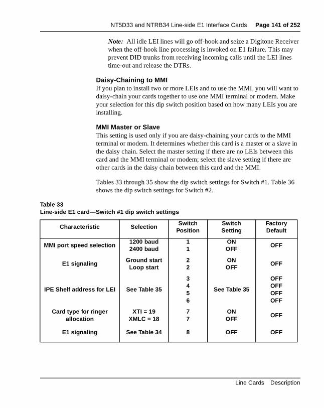
NT5D33 and NTRB34 Line-side E1 Interface Cards Page 141 of 252
r
o ke re
e in is
6
Note: All idle LEI lines will go off-hook and seize a Digitone Receivewhen the off-hook line processing is invoked on E1 failure. This mayprevent DID trunks from receiving incoming calls until the LEI lines time-out and release the DTRs.
Daisy-Chaining to MMI If you plan to install two or more LEIs and to use the MMI, you will want tdaisy-chain your cards together to use one MMI terminal or modem. Mayour selection for this dip switch position based on how many LEIs you ainstalling.
MMI Master or SlaveThis setting is used only if you are daisy-chaining your cards to the MMIterminal or modem. It determines whether this card is a master or a slavthe daisy chain. Select the master setting if there are no LEIs between thcard and the MMI terminal or modem; select the slave setting if there areother cards in the daisy chain between this card and the MMI.
Tables 33 through 35 show the dip switch settings for Switch #1. Table 3shows the dip switch settings for Switch #2.
Table 33Line-side E1 card—Switch #1 dip switch settings
Characteristic Selection Switch Position
Switch Setting
FactoryDefault
MMI port speed selection 1200 baud2400 baud
11
ONOFF
OFF
E1 signaling Ground startLoop start
22
ONOFF
OFF
IPE Shelf address for LEI See Table 35
3456
See Table 35
OFFOFFOFFOFF
Card type for ringer allocation
XTI = 19XMLC = 18
77
ONOFF
OFF
E1 signaling See Table 34 8 OFF OFF
Line Cards Description
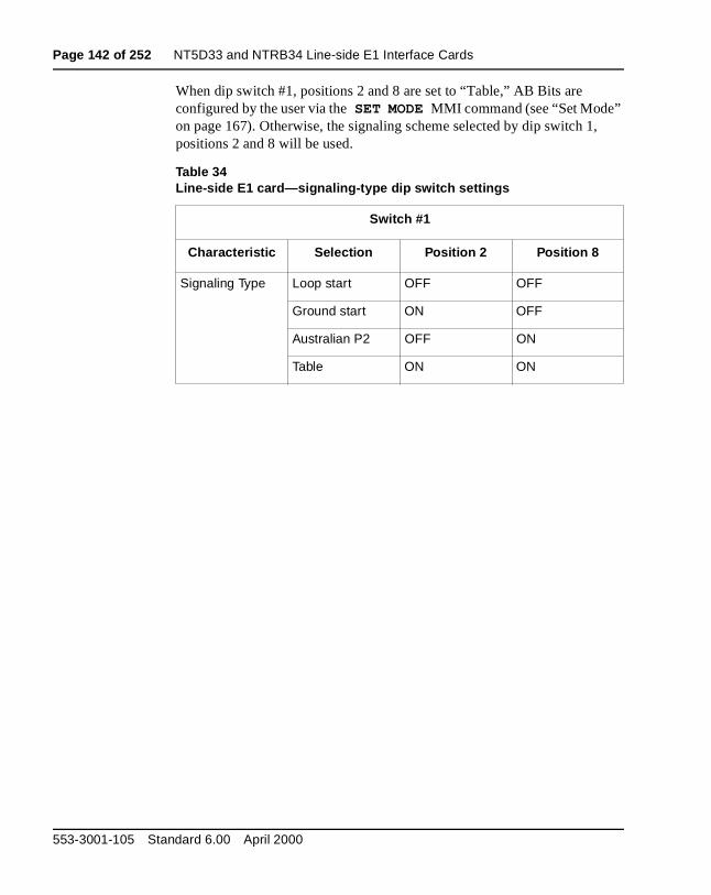
Page 142 of 252 NT5D33 and NTRB34 Line-side E1 Interface Cards
,
When dip switch #1, positions 2 and 8 are set to “Table,” AB Bits are configured by the user via the SET MODE MMI command (see “Set Mode” on page 167). Otherwise, the signaling scheme selected by dip switch 1positions 2 and 8 will be used.
Table 34Line-side E1 card—signaling-type dip switch settings
Switch #1
Characteristic Selection Position 2 Position 8
Signaling Type Loop start OFF OFF
Ground start ON OFF
Australian P2 OFF ON
Table ON ON
553-3001-105 Standard 6.00 April 2000

NT5D33 and NTRB34 Line-side E1 Interface Cards Page 143 of 252
Table 35Line-side E1 card—XPEC address dip switch settings (Switch S1, positions 3-6)
XPEC Address
S1 Switch Position 3
S1 Switch Position 4
S1 Switch Position 5
S1 Switch Position 6
00 OFF OFF OFF OFF
01 ON OFF OFF OFF
02 OFF ON OFF OFF
03 ON ON OFF OFF
04 OFF OFF ON OFF
05 ON OFF ON OFF
06 OFF ON ON OFF
07 ON ON ON OFF
08 OFF OFF OFF ON
09 ON OFF OFF ON
10 OFF ON OFF ON
11 ON ON OFF ON
12 OFF OFF ON ON
13 ON OFF ON ON
14 OFF ON ON ON
15 ON ON ON ON
Line Cards Description
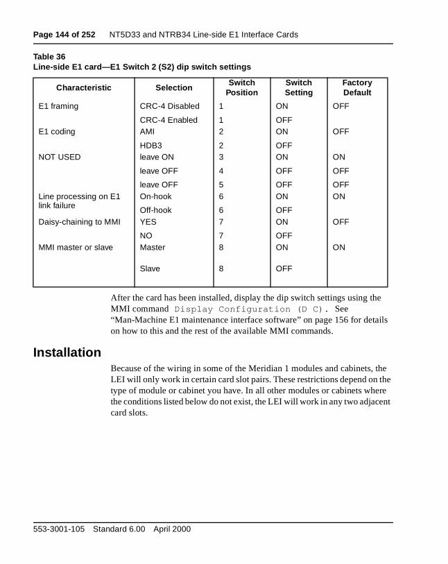
Page 144 of 252 NT5D33 and NTRB34 Line-side E1 Interface Cards
e
ils
the the re nt
Table 36Line-side E1 card—E1 Switch 2 (S2) dip switch settings
After the card has been installed, display the dip switch settings using thMMI command Display Configuration (D C). See “Man-Machine E1 maintenance interface software” on page 156 for detaon how to this and the rest of the available MMI commands.
InstallationBecause of the wiring in some of the Meridian 1 modules and cabinets, LEI will only work in certain card slot pairs. These restrictions depend on type of module or cabinet you have. In all other modules or cabinets whethe conditions listed below do not exist, the LEI will work in any two adjacecard slots.
Characteristic SelectionSwitch
PositionSwitch Setting
FactoryDefault
E1 framing CRC-4 Disabled
CRC-4 Enabled
1
1
ON
OFF
OFF
E1 coding AMI
HDB3
2
2
ON
OFF
OFF
NOT USED leave ON
leave OFF
leave OFF
3
4
5
ON
OFF
OFF
ON
OFF
OFFLine processing on E1 link failure
On-hook
Off-hook
6
6
ON
OFF
ON
Daisy-chaining to MMI YES
NO
7
7
ON
OFF
OFF
MMI master or slave Master 8 ON ON
Slave 8 OFF
553-3001-105 Standard 6.00 April 2000
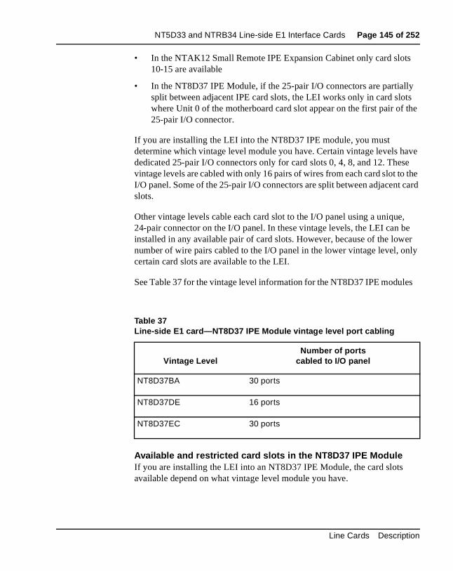
NT5D33 and NTRB34 Line-side E1 Interface Cards Page 145 of 252
s
y ts the
ave se the card
, e er nly
s
• In the NTAK12 Small Remote IPE Expansion Cabinet only card slot10-15 are available
• In the NT8D37 IPE Module, if the 25-pair I/O connectors are partiallsplit between adjacent IPE card slots, the LEI works only in card slowhere Unit 0 of the motherboard card slot appear on the first pair of 25-pair I/O connector.
If you are installing the LEI into the NT8D37 IPE module, you must determine which vintage level module you have. Certain vintage levels hdedicated 25-pair I/O connectors only for card slots 0, 4, 8, and 12. Thevintage levels are cabled with only 16 pairs of wires from each card slot toI/O panel. Some of the 25-pair I/O connectors are split between adjacentslots.
Other vintage levels cable each card slot to the I/O panel using a unique24-pair connector on the I/O panel. In these vintage levels, the LEI can binstalled in any available pair of card slots. However, because of the lownumber of wire pairs cabled to the I/O panel in the lower vintage level, ocertain card slots are available to the LEI.
See Table 37 for the vintage level information for the NT8D37 IPE module
Available and restricted card slots in the NT8D37 IPE ModuleIf you are installing the LEI into an NT8D37 IPE Module, the card slots available depend on what vintage level module you have.
Table 37Line-side E1 card—NT8D37 IPE Module vintage level port cabling
Vintage LevelNumber of ports
cabled to I/O panel
NT8D37BA 30 ports
NT8D37DE 16 ports
NT8D37EC 30 ports
Line Cards Description
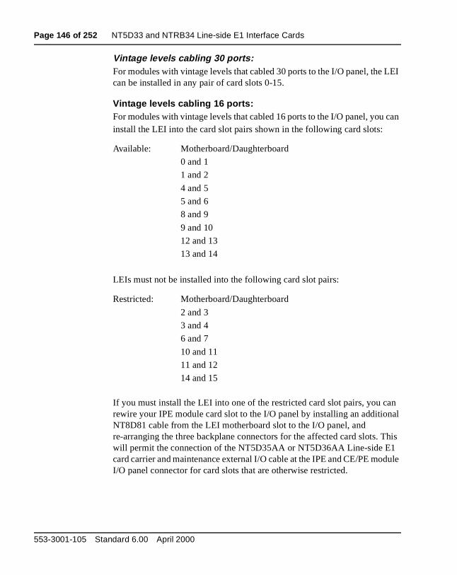
Page 146 of 252 NT5D33 and NTRB34 Line-side E1 Interface Cards
LEI
can
an nal
This dule
Vintage levels cabling 30 ports: For modules with vintage levels that cabled 30 ports to the I/O panel, the can be installed in any pair of card slots 0-15.
Vintage levels cabling 16 ports: For modules with vintage levels that cabled 16 ports to the I/O panel, youinstall the LEI into the card slot pairs shown in the following card slots:
LEIs must not be installed into the following card slot pairs:
If you must install the LEI into one of the restricted card slot pairs, you crewire your IPE module card slot to the I/O panel by installing an additioNT8D81 cable from the LEI motherboard slot to the I/O panel, and re-arranging the three backplane connectors for the affected card slots. will permit the connection of the NT5D35AA or NT5D36AA Line-side E1card carrier and maintenance external I/O cable at the IPE and CE/PE moI/O panel connector for card slots that are otherwise restricted.
Available: Motherboard/Daughterboard
0 and 1
1 and 2
4 and 5
5 and 6
8 and 9
9 and 10
12 and 13
13 and 14
Restricted: Motherboard/Daughterboard
2 and 3
3 and 4
6 and 7
10 and 11
11 and 12
14 and 15
553-3001-105 Standard 6.00 April 2000
NT5D33 and NTRB34 Line-side E1 Interface Cards Page 147 of 252
me
ions.
ed e er
the the cuit
O ide one
9 a tor
el de one B15 Rx ctor
9 r ut. Rx
Alternatively, all LEI connections can be made at the main distribution frainstead of connecting the NT5D35AA or NT5D36AA Line-side E1 card external I/O cable at the I/O panel. This eliminates these card slot restrict
Cabling the line-side E1 card (LEI)After you have set your dip switches and installed the LEI into the selectcard slots, you are ready to cable from the LEI to the LTU equipment, thMMI terminal or modem (optional), an external alarm (optional), and othLEIs for daisy chaining use of the MMI terminal (optional).
The LEI is cabled from its backplane connector through connections frommotherboard circuit card only to the input/output (I/O) panel on the rear ofIPE module. No cable connections are made from the daughterboard circard. The connections from the LEI to the I/O panel are made with the NT8D81AA Tip and Ring cables provided with the IPE module.
Cabling from the I/O panel with the NT5D35AA or NT5D36AA Line-Side E1 I/O cableIn a twisted-pair E1 installation, you will make the connection from the I/panel to the E1 link and other external devices with the NT5D35AA Line-sE1 I/O cable. This cable consists of a 25-pair amphenol connector (P1) onend which plugs into the I/O panel. The other end has four connectors: aDB15 male connector (P2), which plugs into the E1 line; a DB9 male connector (P3), which plugs into an external alarm system; a second DBmale connector (P5), which connects to an MMI terminal or modem; andDB9 female connector (P4), which connects to the next LEI’s P4 connecfor MMI daisy chaining.
In a coaxial E1 installation, you will make the connection from the I/O panto the E1 link and other external devices through the NT5D36AA Line-siE1 I/O cable. This cable consists of a 25-pair amphenol connector (P1) onend which plugs into the I/O panel. The other end has 4 connectors: a Dfemale connector (P2) with an adapter that breaks out Tx (transmit) and(receive) connectors, which that plug into the E1 line; a DB9 male conne(P3), which plugs into an external alarm system; a second DB9 male connector (P5), which connects to an MMI terminal or modem; and a DBfemale connector (P4), which connects to the next LEI’s P4 connector foMMI daisy chaining. The Tx marking on the adapter at P2 is the LEI outpThe E1 data stream coming from the network into the LEI connects at thecoaxial connector.
Line Cards Description
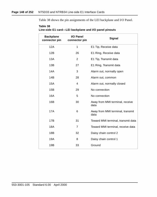
Page 148 of 252 NT5D33 and NTRB34 Line-side E1 Interface Cards
l.
Table 38 shows the pin assignments of the LEI backplane and I/O PaneTable 38Line-side E1 card—LEI backplane and I/O panel pinouts
Backplane connector pin
I/O Panel connector pin Signal
12A 1 E1 Tip, Receive data
12B 26 E1 Ring, Receive data
13A 2 E1 Tip, Transmit data
13B 27 E1 Ring, Transmit data
14A 3 Alarm out, normally open
14B 28 Alarm out, common
15A 4 Alarm out, normally closed
15B 29 No connection
16A 5 No connection
16B 30 Away from MMI terminal, receive data
17A 6 Away from MMI terminal, transmit data
17B 31 Toward MMI terminal, transmit data
18A 7 Toward MMI terminal, receive data
18B 32 Daisy chain control 2
19A 8 Daisy chain control 1
19B 33 Ground
553-3001-105 Standard 6.00 April 2000
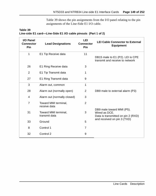
NT5D33 and NTRB34 Line-side E1 Interface Cards Page 149 of 252
n
Table 39 shows the pin assignments from the I/O panel relating to the piassignments of the Line-Side E1 I/O cable.Table 39Line-side E1 card—Line-Side E1 I/O cable pinouts (Part 1 of 2)
I/O Panel Connector
PinLead Designations
LEI Connector
Pin
LEI Cable Connector to External Equipment
1 E1 Tip Receive data 11DB15 male to E1 (P2). LEI is CPE transmit and receive to network
26 E1 Ring Receive data 3
2 E1 Tip Transmit data 1
27 E1 Ring Transmit data 9
3 Alarm out, common 1
28 Alarm out (normally open) 2 DB9 male to external alarm (P3)
4 Alarm out (normally closed) 3
7 Toward MMI terminal, receive data
2
DB9 male toward MMI (P5).Wired as DCE.Data is transmitted on pin 2 (RXD) and received on pin 3 (TXD)
31 Toward MMI terminal, transmit data
3
33 Ground 5
8 Control 1 7
32 Control 2 9
Line Cards Description
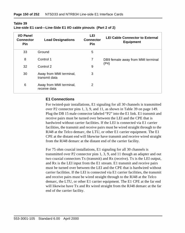
Page 150 of 252 NT5D33 and NTRB34 Line-side E1 Interface Cards
ted 9. nd
the E1 ight
d out ut, s out it
o end far
E1 Connections For twisted-pair installations, E1 signaling for all 30 channels is transmitover P2 connector pins 1, 3, 9, and 11, as shown in Table 39 on page 14Plug the DB 15 male connector labeled “P2” into the E1 link. E1 transmit areceive pairs must be turned over between the LEI and the CPE that is hardwired without carrier facilities. If the LEI is connected via E1 carrier facilities, the transmit and receive pairs must be wired straight through toRJ48 at the Telco demarc, the LTU, or other E1 carrier equipment. The CPE at the distant end will likewise have transmit and receive wired strafrom the RJ48 demarc at the distant end of the carrier facility.
For 75 ohm coaxial installations, E1 signaling for all 30 channels is transmitted over P2 connector pins 1, 3, 9, and 11 though an adapter antwo coaxial connectors Tx (transmit) and Rx (receive). Tx is the LEI outpand Rx is the LEI input from the E1 stream. E1 transmit and receive pairmust be turned over between the LEI and the CPE that is hardwired withcarrier facilities. If the LEI is connected via E1 carrier facilities, the transmand receive pairs must be wired straight through to the RJ48 at the Telcdemarc, the LTU, or other E1 carrier equipment. The E1 CPE at the far will likewise have Tx and Rx wired straight from the RJ48 demarc at the end of the carrier facility.
33 Ground 5
DB9 female away from MMI terminal (P4)
8 Control 1 7
32 Control 2 9
30 Away from MMI terminal, transmit data
3
6 Away from MMI terminal, receive data
2
Table 39Line-side E1 card—Line-Side E1 I/O cable pinouts (Part 2 of 2)
I/O Panel Connector
PinLead Designations
LEI Connector
Pin
LEI Cable Connector to External Equipment
553-3001-105 Standard 6.00 April 2000
NT5D33 and NTRB34 Line-side E1 Interface Cards Page 151 of 252
sing rm.
rts gh ill s it e and l
I
ich data . As an I
d
nal ated IPE ed to
External Alarm ConnectionsP3 connector pins 1, 2 and 3 can be plugged into any external alarm-senhardware. Plug the DB9 male connector labeled “P3” into an external alaThese connections are optional, and the functionality of the LEI is not affected if they are not made.
The MMI monitors the E1 link for specified performance criteria and repoon problems detected. One of the ways it can report information is throuthis external alarm connection. If connected, the LEI’s microprocessor wactivate the external alarm hardware if it detects certain E1 link problemhas classified as alarm levels 1 or 2. See “Man-Machine E1 maintenancinterface software” on page 156, for a detailed description of alarm levelsconfiguration. If an alarm level 1 or 2 is detected by the MMI, the LEI wilclose the contact that is normally open, and will open the contact that is normally closed. The MMI command “Clear Alarm” will return the alarm contacts to their normal state.
MMI ConnectionsP5 connector pins 2, 3, 5, 7 and 9 are used to connect the LEI to the MMterminal, connecting LEIs in a daisy chain for access to a shared MMI terminal. When you log into a LEI, “control 2” is asserted by that card, whinforms all of the other cards not to talk on the bus, but rather to pass thestraight through. The pins labeled “control 1” are reserved for future usewith the external alarm connections, MMI connections are optional. You clink up to 128 LEIs, located in up to 16 separate IPE shelves, to one MMterminal using the daisy chain approach.
If you are installing only one LEI, cable from the DB9 male connector labele“P5” (toward MMI terminal) to one of the COM ports on the back of any TTY, a PC running a terminal emulation program, or a modem. For installations of only one card, no connection is made to the DB9 female connector labeled “P4” (away from MMI terminal).
If you are installing two or more LEIs into your Meridian 1 system, you candaisy chain the MMI port connections together so that only one MMI termiis required for up to 128 LEIs (as shown in Figure 30). Cards can be locin up to 15 separate IPE shelves. You can start with any card slot in yourshelf and connect to any other card slot; connected card slots do not nebe consecutive.
Line Cards Description
Page 152 of 252 NT5D33 and NTRB34 Line-side E1 Interface Cards
al:
o nal
ing
on
Follow this procedure for connecting two or more LEIs to the MMI termin
1 Cable the DB9 male connector labeled “P5” (toward MMI terminal) tone of the COM ports on the back of any TTY, a PC running a termiemulation program, or a modem.
2 Make the connection from the first card to the second card by pluggthe DB9 female connector labeled “P4” (away from MMI terminal) fromthe first card into the DB9 male connector of the second card labeled“P5” (toward MMI terminal).
3 Repeat step 2 for the remaining cards.
4 When you get to the last card in your daisy chain, make no connectifrom the DB9 female connector labeled “P4” (away from MMI terminal).
5 If two LEIs are too far apart to connect the “P4” and “P5” connectorsconnect them with an off-the-shelf DB9 female to DB9 male straight-through extension cable, available at any PC supply store.
553-3001-105 Standard 6.00 April 2000
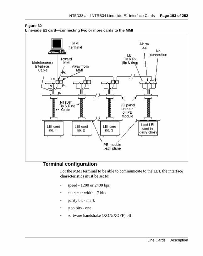
NT5D33 and NTRB34 Line-side E1 Interface Cards Page 153 of 252
Figure 30Line-side E1 card—connecting two or more cards to the MMI
Terminal configurationFor the MMI terminal to be able to communicate to the LEI, the interfacecharacteristics must be set to:
• speed - 1200 or 2400 bps
• character width - 7 bits
• parity bit - mark
• stop bits - one
• software handshake (XON/XOFF) off
Line Cards Description
Page 154 of 252 NT5D33 and NTRB34 Line-side E1 Interface Cards
ide
ause
e
its is in 0 rd
the g is
Software ConfigurationAlthough much of the architecture and many of the features of the Line-sE1 card (LEI) are different from the analog line card, the LEI has been designed to emulate an analog line card to the Meridian 1 software. Becof this, the LEI software configuration is performed the same as for two adjacent analog line cards.
All 30 E1 channels carried by the LEI are individually configured using thAnalog (500/2500) Telephone Administration program (LD10). Use Table 39 on page 149 to determine the correct unit number and the X11 Administration (553-3001-311) for LD10 service-change instructions.
LEI circuitry routes 16 units (0-15) on the motherboard and 14 (0-13) unon the daughterboard to 30 E1 channels. The motherboard circuit cardlocated in the left card slot, and the daughterboard circuit card is locatedright card slot. For example, if you were installing the LEI into card slots and 1, the motherboard would reside in card slot 0 and the daughterboawould reside in card slot 1. In order to configure the terminal equipment through the switch software, you will need to be able to cross-reference E1 channel number to the corresponding card unit number. This mappinshown in Table 40.
Table 40Card unit number to E1 channel mapping (Part 1 of 2)
TN E1 Channel Number
Motherboard 0 1
Motherboard 1 2
Motherboard 2 3
Motherboard 3 4
Motherboard 4 5
Motherboard 5 6
Motherboard 6 7
Motherboard 7 8
Motherboard 8 9
553-3001-105 Standard 6.00 April 2000
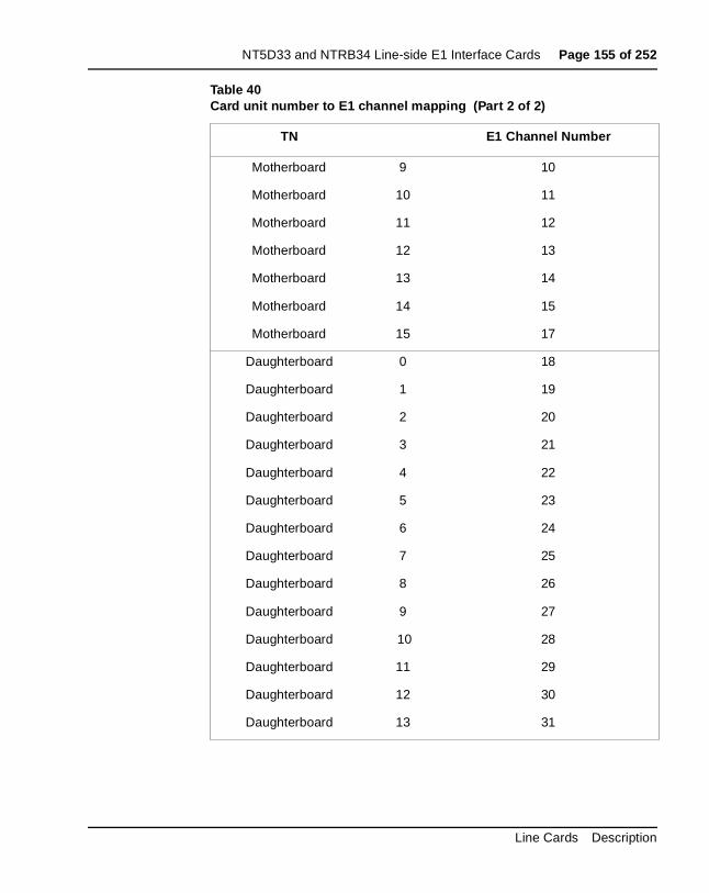
NT5D33 and NTRB34 Line-side E1 Interface Cards Page 155 of 252
Motherboard 9 10
Motherboard 10 11
Motherboard 11 12
Motherboard 12 13
Motherboard 13 14
Motherboard 14 15
Motherboard 15 17
Daughterboard 0 18
Daughterboard 1 19
Daughterboard 2 20
Daughterboard 3 21
Daughterboard 4 22
Daughterboard 5 23
Daughterboard 6 24
Daughterboard 7 25
Daughterboard 8 26
Daughterboard 9 27
Daughterboard 10 28
Daughterboard 11 29
Daughterboard 12 30
Daughterboard 13 31
Table 40Card unit number to E1 channel mapping (Part 2 of 2)
TN E1 Channel Number
Line Cards Description
Page 156 of 252 NT5D33 and NTRB34 Line-side E1 Interface Cards
side ised
I ISP alls
ard fore, LED d in
s not
.
nd e
p,
Disconnect supervisionThe LEI supports distant-end disconnect supervision by opening the tip toward the terminal equipment upon the Meridian 1 system’s detecting adisconnect signal from the distant-end on an established call. The SupervAnalog Line feature (SAL) must be configured in overlay 10 for each LEport. At the prompt FTR respond OSP <CR>, and against FTR respond <CR>. The LEI treats OSP and ISP for both originating and terminating cas hook flash disconnect supervision, also known as cut-off disconnect. Originating calls are outgoing from the terminal equipment. Terminating calls are incoming to the terminal equipment. The LEI does not support battery reversal answer and disconnect supervision on originating calls.
After you have configured the software, you are ready to power-up the cand verify the self-test results. The STATUS LED on the faceplate indicateswhether or not the LEI has successfully passed its self test, and is, therefunctional. When the card is installed, this LED remains lit for two to fiveseconds as the self-test runs. If the self-test completes successfully, theflashes three times and remains lit until the card is configured and enablesoftware, then the LED goes out. The LED will go out if either the motherboard or daughterboard is enabled by the software. If the LED doefollow the pattern described or operates in any other manner (such as continually flashing or remaining weakly lit), the card should be replaced
Man-Machine E1 maintenance interface softwareDescription
The Man-Machine Interface (MMI) provides E1-link diagnostics and historical information for the LEI system. See “Installation and Configuration” on page 137 for instructions on how to install the cabling aconfigure the terminal for the MMI. The following sections will describe thoptions available via the LEI’s MMI terminal and will explain how to set-uconfigure, and use the MMI.
The MMI provides the following maintenance features:
• configurable alarm parameters
• E1-link problem indicator
• current and historical E1-link performance reports
553-3001-105 Standard 6.00 April 2000
NT5D33 and NTRB34 Line-side E1 Interface Cards Page 157 of 252
r
LEI
62.
l of n e vel
r e 36
d n), lear
, ding in
• E1 verification and fault isolation testing
• configuration of A\B bits (North American Standard, Australian P2, ocustomized settings are available)
AlarmsThe MMI may be used to activate alarms for the following E1-link conditions: excessive bit-error rate, frame-slip errors, out-of-frame, loss-of-signal, and blue alarm. Pre-set thresholds and error durations tripalarm notifications. For descriptions of each of these E1-link alarm conditions, see “Performance counters and reporting” on page 176. For instructions on how to set alarm parameters, see “Set Alarm” on page 1For information on accessing alarm reporting, see “Display Alarms” on page 175, “Display Status” on page 175 and “Display Performance” on page 177.
Two levels of alarm severity exist for bit errors. Different threshold and duration settings must be established for each level. When the first leveseverity is reached (alarm level 1), the MMI will cause the external alarmhardware to activate, the RED ALARM LED on the faceplate will be lit, aalarm message will be displayed on the MMI terminal, and an entry will bcreated in the alarm log and printed to the MMI port. When the second leof severity is reached (alarm level 2), the MMI will perform all functions performed at alarm level 1, and, in addition, the LEI will enter line-conditioning mode. In this mode, the LEI will send either “on-hook” o“off-hook” signals for all 30 ports to the Meridian 1, depending on how thdip switch for line processing is set (dip switch 2, position 6). See Tableon page 144.
If the MMI detects E1-link failures for any of the other conditions monitore(out-of-frame, excess frame slips, loss-of-signal, and blue alarm conditiothe LEI automatically performs all alarm level 2 functions. The MMI alsosends a yellow alarm to the distant end LTU. Alarms may be set to self-cwhen the alarm condition is no longer detected. See “Set Clearing” on page 166.
All alarms activated produce a record in the alarm log. The alarm log maintains records for the most recent 100 alarms, and can be displayedprinted, and cleared. The alarm log displays or prints the alarms in descenchronological order, beginning with the most recent alarm. Notifications the alarm log include the date and time of the alarm’s occurrence.
Line Cards Description
Page 158 of 252 NT5D33 and NTRB34 Line-side E1 Interface Cards
r-slip
s on s and
e E1 how
tion ou ed
y dip ide
lus login
card
lf
E1 Performance Counters and ReportsThe MMI maintains performance error counters for the following E1 conditions: errored seconds, bursty seconds, unavailable seconds, frameseconds, and loss-of-frame seconds. The MMI retains E1 performance statistics for the current hour, and for each hour for the previous 24. Fordescriptions of each of these performance error counters and instructionhow to create a report of them and clear them, see “Performance counterreporting” on page 176.
E1 Verification and Fault Isolation TestingThe MMI allows you to perform various tests and will either verify that thE1 is working adequately, or help you to isolate a problem to the LEI, thelink, or the CPE. For descriptions of all of these tests and instructions on to run them, see “Testing” on page 179.
Login and PasswordThe MMI can be accessed through any TTY, PC running a terminal emulaprogram, or modem. After installing the MMI terminal and card cables, yare ready to configure the MMI. For single-card installations, it is accessby entering L<CR> to login. For multiple-card installations connected in adaisy chain, it is accessed by entering L <address>, where the four-digit address is a combination of the two-digit address of the IPE shelf as set bswitch positions on the card Switch 1, positions 3-6, see Table 37, “Line-sE1 card—NT8D37 IPE Module vintage level port cabling,” on page 145, pthe address of the card slot the motherboard occupies. For example, to to a card located in shelf 13, card slot 4, you would type L 13 4 <CR>. Spaces are inserted between the login command (L), the shelf address, and theslot address.
The MMI will now prompt you for a password. The password is “LEILINK ,” and it must be typed in all capital letters.
After you have logged in, the prompt will look like this:
LEI::> (for single-card installations)
LEI::ss cc> (for multi-card installations, where ss represents the sheaddress and cc represents the card slot address.)
553-3001-105 Standard 6.00 April 2000
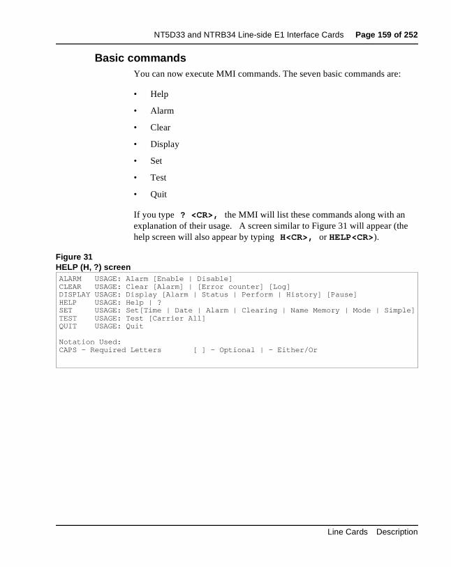
NT5D33 and NTRB34 Line-side E1 Interface Cards Page 159 of 252
:
e
Basic commandsYou can now execute MMI commands. The seven basic commands are
• Help
• Alarm
• Clear
• Display
• Set
• Test
• Quit
If you type ? <CR>, the MMI will list these commands along with an explanation of their usage. A screen similar to Figure 31 will appear (thhelp screen will also appear by typing H<CR>, or HELP<CR>).
Figure 31HELP (H, ?) screenALARM USAGE: Alarm [Enable | Disable]CLEAR USAGE: Clear [Alarm] | [Error counter] [Log]DISPLAY USAGE: Display [Alarm | Status | Perform | History] [Pause]HELP USAGE: Help | ?SET USAGE: Set[Time | Date | Alarm | Clearing | Name Memory | Mode | Simple]TEST USAGE: Test [Carrier All]QUIT USAGE: Quit
Notation Used:CAPS - Required Letters [ ] - Optional | - Either/Or
Line Cards Description
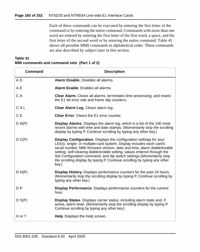
Page 160 of 252 NT5D33 and NTRB34 Line-side E1 Interface Cards
the one the
41 nds
Each of these commands can be executed by entering the first letter of command or by entering the entire command. Commands with more thanword are entered by entering the first letter of the first word, a space, andfirst letter of the second word or by entering the entire command. Tableshows all possible MMI commands in alphabetical order. These commaare also described by subject later in this section.
Table 41MMI commands and command sets (Part 1 of 2)
Command Description
A D Alarm Disable. Disables all alarms.
A E Alarm Enable . Enables all alarms.
C A Clear Alarm. Clears all alarms, terminates time processing, and resets the E1 bit error rate and frame slip counters.
C A L Clear Alarm Log . Clears alarm log.
C E Clear Error . Clears the E1 error counter.
D A(P) Display Alarms . Displays the alarm log, which is a list of the 100 most recent alarms with time and date stamps. (Momentarily stop the scrolling display by typing P. Continue scrolling by typing any other key.)
D C(P) Display Configuration . Displays the configuration settings for your LEI(s), single- or multiple-card system. Display includes each card’s serial number, MMI firmware version, date and time, alarm diable/enable setting, self-clearing diable/enable setting, values entered through the Set Configuration command, and dip switch settings.(Momentarily stop the scrolling display by typing P. Continue scrolling by typing any other key.)
D H(P) Display History . Displays performance counters for the past 24 hours. (Momentarily stop the scrolling display by typing P. Continue scrolling by typing any other key.)
D P Display Performance . Displays performance counters for the current hour.
D S(P) Display Status . Displays carrier status, including alarm state and, if active, alarm level. (Momentarily stop the scrolling display by typing P. Continue scrolling by typing any other key.)
H or ? Help. Displays the Help screen.
553-3001-105 Standard 6.00 April 2000
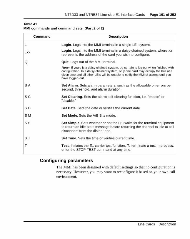
NT5D33 and NTRB34 Line-side E1 Interface Cards Page 161 of 252
n is call
Configuring parametersThe MMI has been designed with default settings so that no configurationecessary. However, you may want to reconfigure it based on your ownenvironment.
L Login . Logs into the MMI terminal in a single-LEI system.
Login . Logs into the MMI terminal in a daisy-chained system, where xx represents the address of the card you wish to configure.
Lxx
Q Quit . Logs out of the MMI terminal.
Note: If yours is a daisy-chained system, be certain to log out when finished with configuration. In a daisy-chained system, only one card may occupy the bus at a given time and all other LEIs will be unable to notify the MMI of alarms until you have logged-out.
S A Set Alarm . Sets alarm parameters, such as the allowable bit-errors per second, threshold, and alarm duration.
S C Set Clearing . Sets the alarm self-clearing function, i.e. ”enable” or ”disable.”
S D Set Date . Sets the date or verifies the current date.
S M Set Mode . Sets the A/B Bits mode.
S S Set Simple . Sets whether or not the LEI waits for the terminal equipment to return an idle-state message before returning the channel to idle at call disconnect from the distant end.
S T Set Time . Sets the time or verifies current time.
T Test . Initiates the E1 carrier test function. To terminate a test in-process, enter the STOP TEST command at any time.
Table 41MMI commands and command sets (Part 2 of 2)
Command Description
Line Cards Description
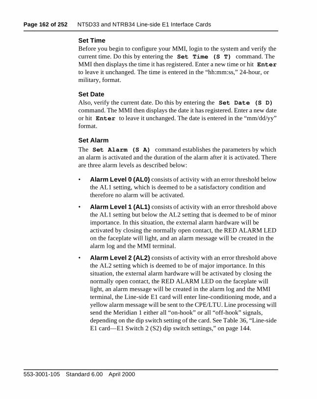
Page 162 of 252 NT5D33 and NTRB34 Line-side E1 Interface Cards
e
r
date y”
ch ere
e or
D he
e
e
I a ill
ide
Set TimeBefore you begin to configure your MMI, login to the system and verify thcurrent time. Do this by entering the Set Time (S T) command. The MMI then displays the time it has registered. Enter a new time or hit Enter to leave it unchanged. The time is entered in the “hh:mm:ss,” 24-hour, omilitary, format.
Set DateAlso, verify the current date. Do this by entering the Set Date (S D) command. The MMI then displays the date it has registered. Enter a newor hit Enter to leave it unchanged. The date is entered in the “mm/dd/yformat.
Set AlarmThe Set Alarm (S A) command establishes the parameters by whian alarm is activated and the duration of the alarm after it is activated. Thare three alarm levels as described below:
• Alarm Level 0 (AL0) consists of activity with an error threshold belowthe AL1 setting, which is deemed to be a satisfactory condition and therefore no alarm will be activated.
• Alarm Level 1 (AL1) consists of activity with an error threshold abovthe AL1 setting but below the AL2 setting that is deemed to be of minimportance. In this situation, the external alarm hardware will be activated by closing the normally open contact, the RED ALARM LEon the faceplate will light, and an alarm message will be created in talarm log and the MMI terminal.
• Alarm Level 2 (AL2) consists of activity with an error threshold abovthe AL2 setting which is deemed to be of major importance. In this situation, the external alarm hardware will be activated by closing thnormally open contact, the RED ALARM LED on the faceplate will light, an alarm message will be created in the alarm log and the MMterminal, the Line-side E1 card will enter line-conditioning mode, andyellow alarm message will be sent to the CPE/LTU. Line processing wsend the Meridian 1 either all “on-hook” or all “off-hook” signals, depending on the dip switch setting of the card. See Table 36, “Line-sE1 card—E1 Switch 2 (S2) dip switch settings,” on page 144.
553-3001-105 Standard 6.00 April 2000
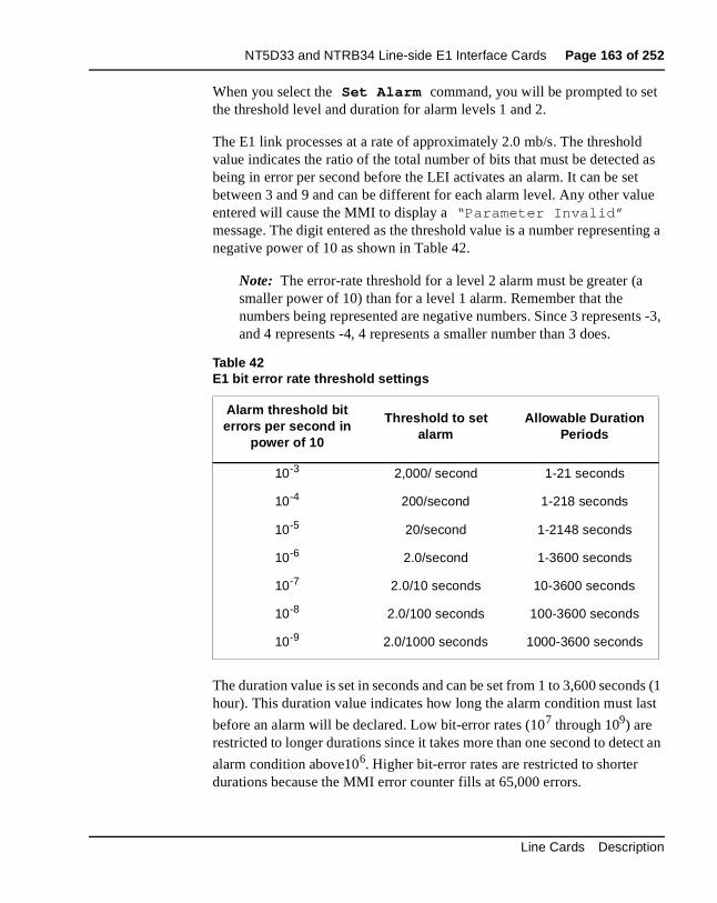
NT5D33 and NTRB34 Line-side E1 Interface Cards Page 163 of 252
d as t lue
ting a
ts -3,
ds (1 st
ct an
When you select the Set Alarm command, you will be prompted to setthe threshold level and duration for alarm levels 1 and 2.
The E1 link processes at a rate of approximately 2.0 mb/s. The thresholvalue indicates the ratio of the total number of bits that must be detectedbeing in error per second before the LEI activates an alarm. It can be sebetween 3 and 9 and can be different for each alarm level. Any other vaentered will cause the MMI to display a “Parameter Invalid” message. The digit entered as the threshold value is a number represennegative power of 10 as shown in Table 42.
Note: The error-rate threshold for a level 2 alarm must be greater (asmaller power of 10) than for a level 1 alarm. Remember that the numbers being represented are negative numbers. Since 3 represenand 4 represents -4, 4 represents a smaller number than 3 does.
The duration value is set in seconds and can be set from 1 to 3,600 seconhour). This duration value indicates how long the alarm condition must la
before an alarm will be declared. Low bit-error rates (107 through 109) are restricted to longer durations since it takes more than one second to dete
alarm condition above106. Higher bit-error rates are restricted to shorter durations because the MMI error counter fills at 65,000 errors.
Table 42E1 bit error rate threshold settings
Alarm threshold bit errors per second in
power of 10
Threshold to set alarm
Allowable Duration Periods
10-3 2,000/ second 1-21 seconds
10-4 200/second 1-218 seconds
10-5 20/second 1-2148 seconds
10-6 2.0/second 1-3600 seconds
10-7 2.0/10 seconds 10-3600 seconds
10-8 2.0/100 seconds 100-3600 seconds
10-9 2.0/1000 seconds 1000-3600 seconds
Line Cards Description
Page 164 of 252 NT5D33 and NTRB34 Line-side E1 Interface Cards
,
by o was . If
rm
kly
g
ll be oon will ors r the ion this
ting m. If me
The
The alarm indications (LEDs and external alarm contacts) will clear automatically after the specified period, or duration, has expired if the Set Clearing (S C) “Enable Self Clearing” option has been set. Otherwisethe alarm will continue until the command Clear Alarm (C A) has been entered. When an alarm is cleared, all activity causedthe alarm indications will be cleared: the external alarm hardware will bedeactivated (the contact normally open will be reopened), the LED will gout, an entry will be made in the alarm log of the date and time the alarm cleared, and carrier-fail line supervision will cease (for alarm level 2 only)self-clearing alarm indications have been disabled, carrier-fail line supervision will terminate when the alarm condition has ceased, but the external alarm contact and faceplate LED will remain active until the alais cleared.
A heavy bit-error rate can cause 200 bit errors to occur much more quicthan100 seconds. This will cause the alarm to be declared sooner.
An alarm condition will not be automatically cleared until the system no longer detects the respective bit error threshold during the correspondinduration period. For example, if AL1 threshold of 6 (representing 10-6) isspecified, and a duration period of 100 seconds is specified, an alarm wiactivated if more than 200 bit errors occur in any 100 second period. As sas the alarm is activated, the bit counter will be reset to 0. If the next 100seconds pass, and less than 200 bit errors are detected, then the alarm clear after the alarm’s duration period. However, if more than 200 bit errare detected in the next 100 seconds, the alarm condition will continue fodesignated time period. The alarm will finally clear when the alarm conditis no longer detected for the designated period either by self-clearing (if function is enabled), or when the Clear Alarm (C A) command is entered.
In addition to bit errors, the Set Alarm function sets parameters for detecframe-slip errors by establishing a threshold necessary to activate an alarthe threshold value is exceeded, a level 2 alarm will be activated. The fraslip threshold can be specified from 1 to 255 frame slips per time period. duration time period can be specified from 1 to 24 hours.
553-3001-105 Standard 6.00 April 2000
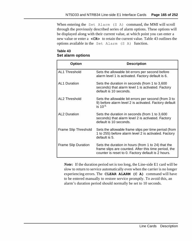
NT5D33 and NTRB34 Line-side E1 Interface Cards Page 165 of 252
will a e
be ger
When entering the Set Alarm (S A) command, the MMI will scroll through the previously described series of alarm options. These optionsbe displayed along with their current value, at which point you can enternew value or enter a <CR> to retain the current value. Table 43 outlines thoptions available in the Set Alarm (S A) function.
Note: If the duration period set is too long, the Line-side E1 card will slow to return to service automatically even when the carrier is no lonexperiencing errors. The CLEAR ALARM (C A) command will have to be entered manually to restore service promptly. To avoid this, analarm’s duration period should normally be set to 10 seconds.
Table 43Set alarm options
Option Description
AL1 Threshold Sets the allowable bit errors per second before alarm level 1 is activated. Factory default is 6.
AL1 Duration Sets the duration in seconds (from 1 to 3,600 seconds) that alarm level 1 is activated. Factory default is 10 seconds.
AL2 Threshold Sets the allowable bit errors per second (from 3 to 9) before alarm level 2 is activated. Factory default is 10-5.
AL2 Duration Sets the duration in seconds (from 1 to 3,600 seconds) that alarm level 2 is activated. Factory default is 10 seconds.
Frame Slip Threshold Sets the allowable frame slips per time period (from 1 to 255) before alarm level 2 is activated. Factory default is 5.
Frame Slip Duration Sets the duration in hours (from 1 to 24) that the frame slips are counted. After this time period, the counter is reset to 0. Factory default is 2 hours.
Line Cards Description
Page 166 of 252 NT5D33 and NTRB34 Line-side E1 Interface Cards
PE is
ces
nds nal te in
the le
e
Set ClearingThe SET CLEARING (S C) command allows you to enable or disableself-clearing of alarms by responding to the question: Enable Self Clearing? (YES or NO) . If YES is chosen (the factory default setting), the system will automatically clear (reset) alarms after the alarmcondition is no longer detected. Choosing the NO option will cause the system to continue the alarm condition until the Clear Alarm (C A) command is entered. Line processing and yellow alarm indication to the Cwill terminate as soon as the alarm condition clears, even if self-clearingdisabled.
Set SimpleThe SET SIMPLE command controls call tear-down signaling when thedistant end disconnects from a call. Release 2 of the AB vintage introduthis feature.
When the distant end terminates a call, Release 1 of LEI’s AB vintage sea disconnect message to the terminal equipment and waits for the termiequipment to go idle before going idle itself. A NO response (see Figure 32)to the S S command configures Release 2 (and above) boards to operathis way.
Release 2 of AB vintage LEIs gives the administrator the option of usingsignaling described above, or of configuring the LEI to take its channel idimmediately after sending the call-disconnect message. A YES response (see Figure 33) to the S S command, the default configuration for Releas2 (and above) boards, configures the LEI to operate in this way.
553-3001-105 Standard 6.00 April 2000
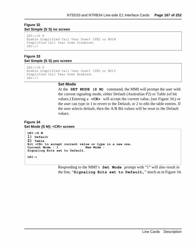
NT5D33 and NTRB34 Line-side E1 Interface Cards Page 167 of 252
t r s. If ult
Figure 32Set Simple (S S) no screen
Figure 33Set Simple (S S) yes screen
Set ModeAt the SET MODE (S M) command, the MMI will prompt the user withthe current signaling mode, either Default (Australian P2) or Table (of bivalues.) Entering a <CR> will accept the current value, (see Figure 34,) othe user can type in 1 to revert to the Default, or 2 to edit the table entriethe user selects default, then the A/B Bit values will be reset to the Defavalues.
Figure 34Set Mode (S M): <CR> screen
Responding to the MMI’s Set Mode prompt with “1” will also result in the line, “Signaling Bits set to Default, ” much as in Figure 34.
LEI::>S SEnable Simplified Call Tear Down? (YES or NO)NSimplified Call Tear Down Disabled.LEI::>
LEI::>S SEnable Simplified Call Tear Down? (YES or NO)YSimplified Call Tear Down Enabled.LEI::>
LEI:>S M1) Default2) TableHit <CR> to accept current value or type in a new one.Current Mode : 1 New Mode :Signaling Bits set to Default.
LEI:>
Line Cards Description
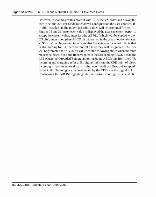
Page 168 of 252 NT5D33 and NTRB34 Line-side E1 Interface Cards
. If
e tes,
that ser le the E. . d . .
However, responding to this prompt with 2 selects “Table” and allows the user to set the A/B Bit Mode to whatever configuration the user chooses“Table” is selected, the individual table values will be prompted for, see Figures 35 and 36. After each value is displayed the user can enter <CR> to accept the current value, enter just the AB bits (which will be copied to thCD bits), enter a complete ABCD bit pattern, or, in the case of optional staa ‘N’ or ‘n’ can be entered to indicate that the state is not needed. Notein D4 Framing for E1, there are no CD bits so they will be ignored. The uwill be prompted for ABCD bit values for the following states when the tabmode is selected. Send and Receive refer to the LEI sending ABCD bits toCPE (Customer Provided Equipment) or receiving ABCD bits from the CPIncoming and Outgoing refer to E1 digital link from the CPE point of viewIncoming is thus an external call arriving over the digital link and accepteby the CPE. Outgoing is a call originated by the CPE over the digital linkConfiguring the A/B Bit Signaling table is illustrated in Figures 35 and 36
553-3001-105 Standard 6.00 April 2000
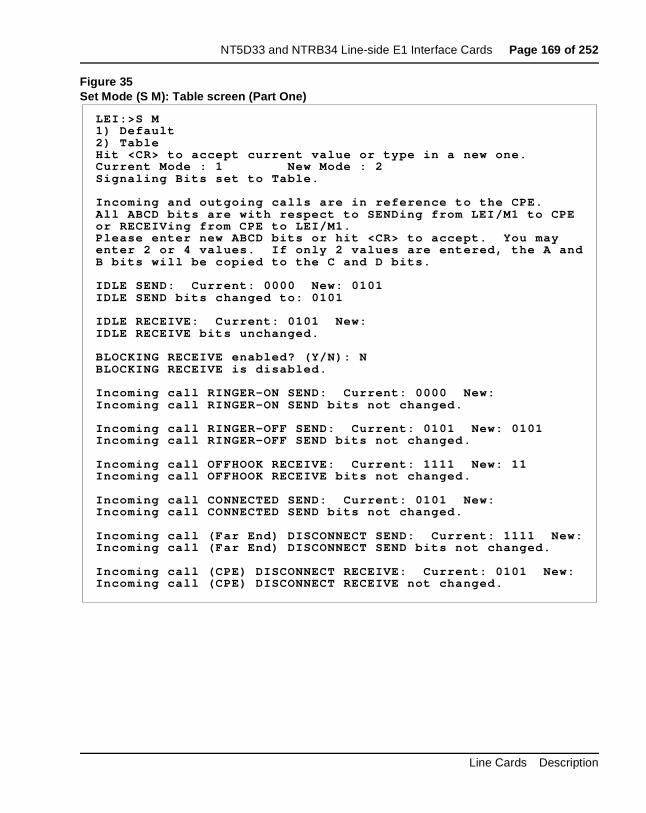
NT5D33 and NTRB34 Line-side E1 Interface Cards Page 169 of 252
Figure 35Set Mode (S M): Table screen (Part One)
LEI:>S M1) Default2) TableHit <CR> to accept current value or type in a new one.Current Mode : 1 New Mode : 2Signaling Bits set to Table.
Incoming and outgoing calls are in reference to the CPE.All ABCD bits are with respect to SENDing from LEI/M1 to CPEor RECEIVing from CPE to LEI/M1.Please enter new ABCD bits or hit <CR> to accept. You mayenter 2 or 4 values. If only 2 values are entered, the A andB bits will be copied to the C and D bits.
IDLE SEND: Current: 0000 New: 0101IDLE SEND bits changed to: 0101
IDLE RECEIVE: Current: 0101 New:IDLE RECEIVE bits unchanged.
BLOCKING RECEIVE enabled? (Y/N): NBLOCKING RECEIVE is disabled.
Incoming call RINGER-ON SEND: Current: 0000 New:Incoming call RINGER-ON SEND bits not changed.
Incoming call RINGER-OFF SEND: Current: 0101 New: 0101Incoming call RINGER-OFF SEND bits not changed.
Incoming call OFFHOOK RECEIVE: Current: 1111 New: 11Incoming call OFFHOOK RECEIVE bits not changed.
Incoming call CONNECTED SEND: Current: 0101 New:Incoming call CONNECTED SEND bits not changed.
Incoming call (Far End) DISCONNECT SEND: Current: 1111 New:Incoming call (Far End) DISCONNECT SEND bits not changed.
Incoming call (CPE) DISCONNECT RECEIVE: Current: 0101 New:Incoming call (CPE) DISCONNECT RECEIVE not changed.
Line Cards Description
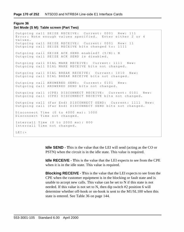
Page 170 of 252 NT5D33 and NTRB34 Line-side E1 Interface Cards
E
e s
is
Figure 36Set Mode (S M): Table screen (Part Two)
Idle SEND - This is the value that the LEI will send (acting as the CO orPSTN) when the circuit is in the idle state. This value is required.
Idle RECEIVE - This is the value that the LEI expects to see from the CPwhen it is in the idle state. This value is required.
Blocking RECEIVE - This is the value that the LEI expects to see from thCPE when the customer equipment is in the blocking or fault state and iunable to accept new calls. This value can be set to N if this state is not needed. If this value is not set to N, then dip switch #2 position 6 will determine whether off-hook or on-hook is sent to the M1/SL100 when thstate is entered. See Table 36 on page 144.
Outgo ing ca l l SE IZE RECEIVE : Cu r ren t : 0001 N ew: 111Er ro r : No te enou gh va lues spec i f i ed . En te r e i t he r 2 o r 4va lues .Ou tgo ing ca l l SE IZE RECEIVE : Cu r ren t : 0001 N ew: 11Ou tgo ing ca l l SE IZE RECEIVE b i t s changed to : 1 111
Ou tgo ing ca l l SE IZE ACK SEND enab led? (Y /N ) : NOu tgo ing ca l l SE IZE ACK SEND i s d i sab led .
Ou tgo ing ca l l D I AL MAKE RECEIVE : Cu r ren t : 111 1 New:Ou tgo ing ca l l D I AL MAKE RECEIVE b i t s no t chang ed .
Ou tgo ing ca l l D I AL BREAK RECEIVE : Cu r ren t : 10 10 New:Ou tgo ing ca l l D I AL BREAK RECEIVE b i t s no t chan ged .
Ou tgo ing ca l l AN SWERED SEND: Cu r ren t : 0101 N ew:Ou tgo ing ca l l AN SWERED SEND b i t s no t changed .
Ou tgo ing ca l l (C PE) D ISCONNECT RECEIVE : Cu r re n t : 0101 New:Ou tgo ing ca l l (C PE) D ISCONNECT RECEIVE b i t s no t changed .
Ou tgo ing ca l l (F a r End ) D ISCONNECT SEND: Cu r r en t : 1111 New:Ou tgo ing ca l l (F a r End ) D ISCONNECT SEND b i t s n o t changed .
D i sconnec t T ime (0 t o 4000 ms ) : 1000D isconnec t T ime no t changed .
In te r ca l l T ime ( 0 t o 2000 ms ) : 800In te rca l l T ime n o t changed .
LE I :>
553-3001-105 Standard 6.00 April 2000
NT5D33 and NTRB34 Line-side E1 Interface Cards Page 171 of 252
uld
the
ook ue is
This
es to
a
y for tart
e is
Incoming call Ringer ON SEND - This is the value that the LEI will sendto indicate that a call is incoming to the CPE and that ringing voltage shobe applied at the CPE. This value is required.
Incoming call Ringer OFF SEND - This is the value that the LEI will sendto indicate that a call is incoming to the CPE and that the ring cycle is inoff portion of the cadence. This value is required.
Incoming call Offhook RECEIVE - This is the value that the LEI expectsto see from the CPE when the customer equipment has gone to an off hstate which indicates that the incoming call has been answered. This valrequired.
Incoming call CONNECTED SEND - This is the value that the LEI will send to the CPE to indicate that it has seen and recognized the off hookindication sent by the CPE. The call is considered fully connected at thispoint. This value is required.
Incoming call (Distant End) DISCONNECT SEND - This is the value that the LEI will send to indicate that the distant end has released the call value is required.
Incoming call (CPE) DISCONNECT RECEIVE - This is the value that the LEI expects to see from the CPE when the customer equipment wishend the call. This value is required.
Outgoing call SEIZE RECEIVE - This is the value that the LEI will expectto see when the CPE goes to an off hook condition and wishes to initiatecall. This value is required.
Outgoing call SEIZE ACK SEND - This is the value that the LEI will sendto indicate that the seized condition has been noted and the M-1 is readdial digits. This value can be set to N if it is not required such as in a loop scase.
Outgoing call DIAL MAKE RECEIVE - This is the value that the LEI expects to see from the CPE during the make part of the digit. This valurequired.
Line Cards Description
Page 172 of 252 NT5D33 and NTRB34 Line-side E1 Interface Cards
e is
es to
This
f the d for
ll.
d. ard n
d.
ll
Outgoing call DIAL BREAK RECEIVE - This is the value that the LEI expects to see from the CPE during the break part of the digit. This valurequired.
Outgoing call ANSWERED SEND - This is the value that the LEI will send to indicate that the distant end has answered the call. This value isrequired.
Outgoing call (CPE) DISCONNECT RECEIVE - This is the value that the LEI expects to see from the CPE when the customer equipment wishend the call. This value is required.
Outgoing call (Distant End) DISCONNECT SEND - This is the value that the LEI will send to indicate that the distant end has released the call value is required.
Disconnect Time - This is the number of milliseconds that the LEI will send the disconnect signal to the CPE before reverting to the idle state. ICPE reverts to a connected state during this time, it will be ignored. Thisvalue is only used when disconnect supervision is available and is needethe signaling type in use. It is used when the distant end initiates the disconnect. For loop start cases, this value is not used.
Intercall (release guard) Time - This is the number of milliseconds thatthe LEI will maintain the idle signal to the CPE before initiating a new caThe CPE should not initiate a new call during this time, if it does so, the off-hook indication will be ignored until the release guard time has expireThis value defaults to 0 which relies on the M-1 to observe the proper gutime. If a non-zero value is entered, off-hook from the CPE and Ringer-Ocommands from the M1/SL100 will be ignored until this timer has expire
Display Configuration (D C)The Display Configuration (D C) command displays the variousconfiguration settings established for the LEI. Entering this command wicause a screen similar to Figure 37 to appear:
553-3001-105 Standard 6.00 April 2000
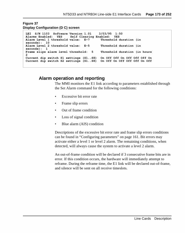
NT5D33 and NTRB34 Line-side E1 Interface Cards Page 173 of 252
gh
ns
in
e,
Figure 37Display Configuration (D C) screen
Alarm operation and reportingThe MMI monitors the E1 link according to parameters established throuthe Set Alarm command for the following conditions:
• Excessive bit error rate
• Frame slip errors
• Out of frame condition
• Loss of signal condition
• Blue alarm (AIS) condition
Descriptions of the excessive bit error rate and frame slip errors conditiocan be found in “Configuring parameters” on page 161. Bit errors may activate either a level 1 or level 2 alarm. The remaining conditions, whendetected, will always cause the system to activate a level 2 alarm.
An out-of-frame condition will be declared if 3 consecutive frame bits areerror. If this condition occurs, the hardware will immediately attempt to reframe. During the reframe time, the E1 link will be declared out-of-framand silence will be sent on all receive timeslots.
LEI S/N 1103 Software Version 1.01 3/03/95 1:50Alarms Enabled: YES Self Clearing Enabled: YESAlarm Level 1 threshold value: E-7 Threshold duration (inseconds): 10Alarm Level 2 threshold value: E-5 Threshold duration (inseconds): 1Frame slips alarm level threshold: 5 Threshold duration (in hours )2Current dip switch S1 settings (S1..S8) On Off Off On Off Off Off OnCurrent dip switch S2 settings (S1..S8) On Off On Off Off Off On Off
Line Cards Description
Page 174 of 252 NT5D33 and NTRB34 Line-side E1 Interface Cards
ive e E1
is red, if,
ue
ion. If red, if,
ue
ge
rm
en
line
de
ed
A loss of signal condition is declared if a full frame (255 bits) of consecutzeros have been detected at the receive inputs. If this condition occurs, thlink will automatically attempt to resynchronize with the distant end. If thcondition occurs for more than two seconds, a level 2 alarm will be declaand silence will be sent on all receive timeslots. The alarm will be clearedafter two seconds, neither a loss of signal, out-of-frame condition, nor blalarm condition occurs.
If a repeating device loses signal, it will immediately begin sending an unframed signal of all ones to the distant end to indicate an alarm conditThis condition is called a blue alarm, or an alarm indication signal (AIS).an AIS is detected for more than two seconds, a level 2 alarm will be declaand silence will be sent on all receive timeslots. The alarm will be clearedafter two seconds, neither a loss of signal, out-of-frame condition, nor blalarm condition occurs.
Alarm DisableThe Alarm Disable (A D) command disables the external alarm contacts. When this command is typed in, the MMI will display the messaAlarms Disabled and the MAINT LED will light. In this mode, no yellow alarms are sent and the LEI will not enter line processing mode. Alamessages will still be to be sent on the MMI terminal and the LED will continue to indicate alarm conditions.
Alarm EnableThe Alarm Enable (A E) command does the reverse of the Alarm Disable (A D) command. It enables the external alarm contacts. Whthis command is typed in, the MMI will display the message Alarms Enabled . In this mode, yellow alarms can be sent and the LEI can enter processing mode.
Clear Alarm The Clear Alarm (C A) command will clear all activity initiated by an alarm: the external alarm hardware will be deactivated (the contact normally open will be reopened), the LED will go out, an entry will be main the alarm log of the date and time the alarm was cleared, and line processing will cease (for alarm level 2 only). When this command is typin, MMI will display the message Alarm acknowledged . If the alarm condition still exists, an alarm will be declared again.
553-3001-105 Standard 6.00 April 2000
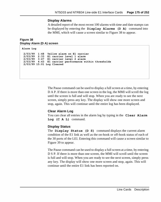
NT5D33 and NTRB34 Line-side E1 Interface Cards Page 175 of 252
can
tering og
d
of r to
tering en ress ill
Display AlarmsA detailed report of the most recent 100 alarms with time and date stampsbe displayed by entering the Display Alarms (D A) command into the MMI, which will cause a screen similar to Figure 38 to appear.
Figure 38Display Alarm (D A) screen
The Pause command can be used to display a full screen at a time, by enD A P. If there is more than one screen in the log, the MMI will scroll the luntil the screen is full and will stop. When you are ready to see the next screen, simply press any key. The display will show one more screen anstop, again. This will continue until the entire log has been displayed.
Clear Alarm LogYou can clear all entries in the alarm log by typing in the Clear Alarm Log (C A L) command.
Display StatusThe Display Status (D S) command displays the current alarm condition of the E1 link as well as the on-hook or off-hook status of eachthe 30 ports of the LEI. Entering this command will cause a screen similaFigure 39 to appear.
The Pause command can be used to display a full screen at a time, by enD S P. If there is more than one screen, the MMI will scroll until the screis full and will stop. When you are ready to see the next screen, simply pany key. The display will show one more screen and stop, again. This wcontinue until the entire E1 link has been reported on.
Alarm Log
2/03/99 1:48 Yellow alarm on E1 carrier 2/03/99 2:33 E1 carrier level 1 alarm 2/03/99 3:47 E1 carrier level 2 alarm 2/03/99 4:43 E1 carrier performance within thresholds 2/03/99 15:01 Log Cleared
Line Cards Description
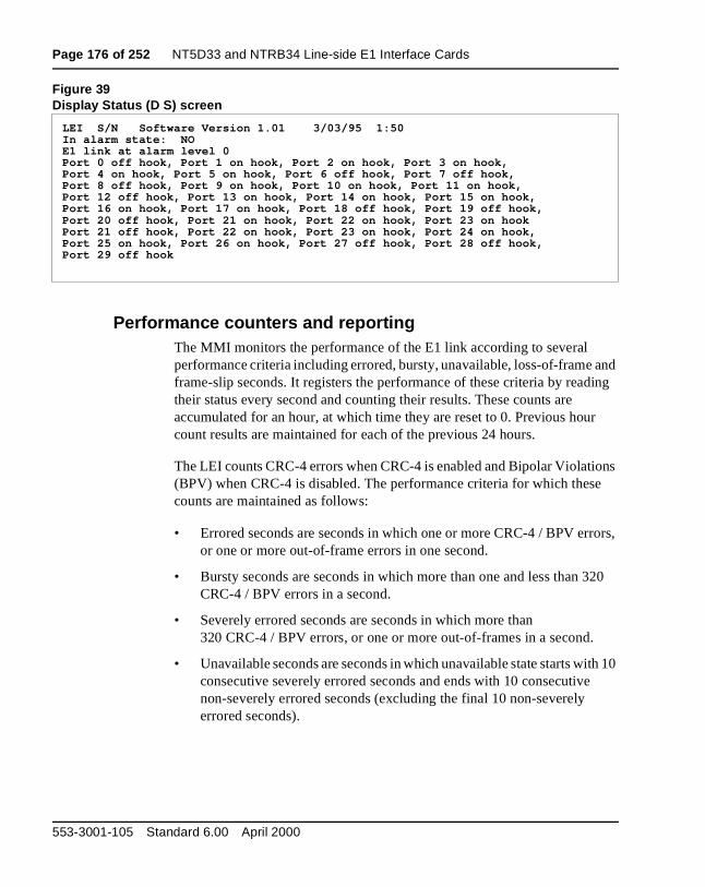
Page 176 of 252 NT5D33 and NTRB34 Line-side E1 Interface Cards
and ing
r
ns
ors,
20
th 10
Figure 39Display Status (D S) screen
Performance counters and reportingThe MMI monitors the performance of the E1 link according to several performance criteria including errored, bursty, unavailable, loss-of-frame frame-slip seconds. It registers the performance of these criteria by readtheir status every second and counting their results. These counts are accumulated for an hour, at which time they are reset to 0. Previous houcount results are maintained for each of the previous 24 hours.
The LEI counts CRC-4 errors when CRC-4 is enabled and Bipolar Violatio(BPV) when CRC-4 is disabled. The performance criteria for which thesecounts are maintained as follows:
• Errored seconds are seconds in which one or more CRC-4 / BPV error one or more out-of-frame errors in one second.
• Bursty seconds are seconds in which more than one and less than 3CRC-4 / BPV errors in a second.
• Severely errored seconds are seconds in which more than 320 CRC-4 / BPV errors, or one or more out-of-frames in a second.
• Unavailable seconds are seconds in which unavailable state starts wiconsecutive severely errored seconds and ends with 10 consecutivenon-severely errored seconds (excluding the final 10 non-severely errored seconds).
LEI S/N Software Version 1.01 3/03/95 1:50In alarm state: NOE1 link at alarm level 0Port 0 off hook, Port 1 on hook, Port 2 on hook, Port 3 on hook,Port 4 on hook, Port 5 on hook, Port 6 off hook, Port 7 off hook,Port 8 off hook, Port 9 on hook, Port 10 on hook, Port 11 on hook,Port 12 off hook, Port 13 on hook, Port 14 on hook, Port 15 on hook,Port 16 on hook, Port 17 on hook, Port 18 off hook, Port 19 off hook ,Port 20 off hook, Port 21 on hook, Port 22 on hook, Port 23 on hookPort 21 off hook, Port 22 on hook, Port 23 on hook, Port 24 on hook,Port 25 on hook, Port 26 on hook, Port 27 off hook, Port 28 off hook ,Port 29 off hook
553-3001-105 Standard 6.00 April 2000
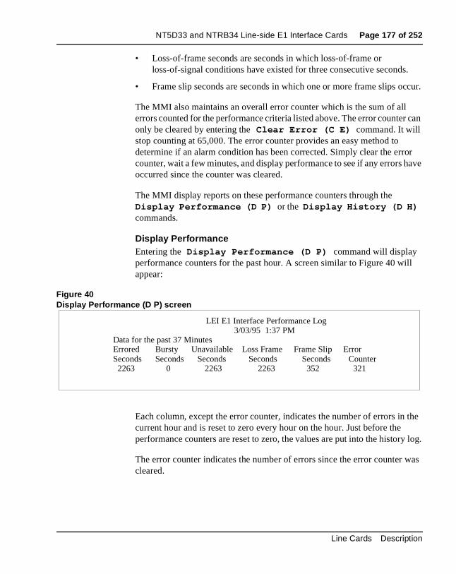
NT5D33 and NTRB34 Line-side E1 Interface Cards Page 177 of 252
.
ccur.
r can
or have
ll
the y log.
was
• Loss-of-frame seconds are seconds in which loss-of-frame or loss-of-signal conditions have existed for three consecutive seconds
• Frame slip seconds are seconds in which one or more frame slips o
The MMI also maintains an overall error counter which is the sum of all errors counted for the performance criteria listed above. The error counteonly be cleared by entering the Clear Error (C E) command. It will stop counting at 65,000. The error counter provides an easy method to determine if an alarm condition has been corrected. Simply clear the errcounter, wait a few minutes, and display performance to see if any errors occurred since the counter was cleared.
The MMI display reports on these performance counters through the Display Performance (D P) or the Display History (D H) commands.
Display PerformanceEntering the Display Performance (D P) command will display performance counters for the past hour. A screen similar to Figure 40 wiappear:
Figure 40Display Performance (D P) screen
Each column, except the error counter, indicates the number of errors incurrent hour and is reset to zero every hour on the hour. Just before theperformance counters are reset to zero, the values are put into the histor
The error counter indicates the number of errors since the error counter cleared.
LEI E1 Interface Performance Log 3/03/95 1:37 PM
Data for the past 37 MinutesErrored Bursty Unavailable Loss Frame Frame Slip ErrorSeconds Seconds Seconds Seconds Seconds Counter 2263 0 2263 2263 352 321
Line Cards Description
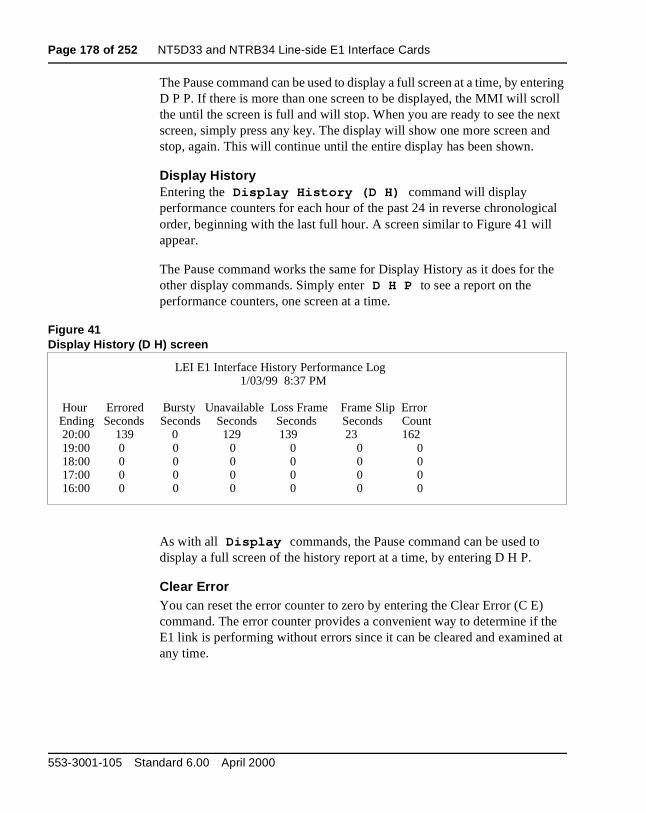
Page 178 of 252 NT5D33 and NTRB34 Line-side E1 Interface Cards
tering oll ext d
ical
he
he d at
The Pause command can be used to display a full screen at a time, by enD P P. If there is more than one screen to be displayed, the MMI will scrthe until the screen is full and will stop. When you are ready to see the nscreen, simply press any key. The display will show one more screen anstop, again. This will continue until the entire display has been shown.
Display HistoryEntering the Display History (D H) command will display performance counters for each hour of the past 24 in reverse chronologorder, beginning with the last full hour. A screen similar to Figure 41 willappear.
The Pause command works the same for Display History as it does for tother display commands. Simply enter D H P to see a report on the performance counters, one screen at a time.
Figure 41Display History (D H) screen
As with all Display commands, the Pause command can be used to display a full screen of the history report at a time, by entering D H P.
Clear ErrorYou can reset the error counter to zero by entering the Clear Error (C E)command. The error counter provides a convenient way to determine if tE1 link is performing without errors since it can be cleared and examineany time.
LEI E1 Interface History Performance Log 1/03/99 8:37 PM
Hour Errored Bursty Unavailable Loss Frame Frame Slip ErrorEnding Seconds Seconds Seconds Seconds Seconds Count 20:00 139 0 129 139 23 162 19:00 0 0 0 0 0 0 18:00 0 0 0 0 0 0 17:00 0 0 0 0 0 0 16:00 0 0 0 0 0 0
553-3001-105 Standard 6.00 April 2000
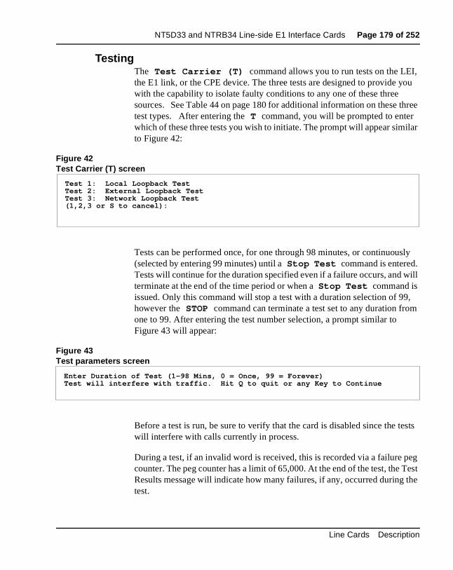
NT5D33 and NTRB34 Line-side E1 Interface Cards Page 179 of 252
, ou
three
ilar
ly
ill
, m
ests
eg Test the
TestingThe Test Carrier (T) command allows you to run tests on the LEIthe E1 link, or the CPE device. The three tests are designed to provide ywith the capability to isolate faulty conditions to any one of these three sources. See Table 44 on page 180 for additional information on these test types. After entering the T command, you will be prompted to enter which of these three tests you wish to initiate. The prompt will appear simto Figure 42:
Figure 42Test Carrier (T) screen
Tests can be performed once, for one through 98 minutes, or continuous(selected by entering 99 minutes) until a Stop Test command is entered. Tests will continue for the duration specified even if a failure occurs, and wterminate at the end of the time period or when a Stop Test command is issued. Only this command will stop a test with a duration selection of 99however the STOP command can terminate a test set to any duration froone to 99. After entering the test number selection, a prompt similar to Figure 43 will appear:
Figure 43Test parameters screen
Before a test is run, be sure to verify that the card is disabled since the twill interfere with calls currently in process.
During a test, if an invalid word is received, this is recorded via a failure pcounter. The peg counter has a limit of 65,000. At the end of the test, the Results message will indicate how many failures, if any, occurred duringtest.
Test 1: Local Loopback TestTest 2: External Loopback TestTest 3: Network Loopback Test(1,2,3 or S to cancel):
Enter Duration of Test (1-98 Mins, 0 = Once, 99 = Forever)Test will interfere with traffic. Hit Q to quit or any Key to Continue
Line Cards Description
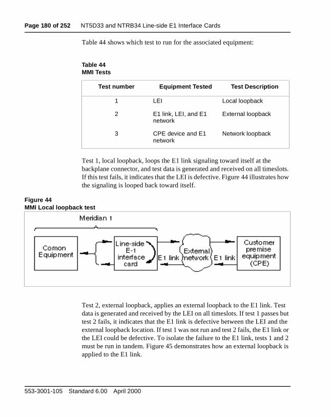
Page 180 of 252 NT5D33 and NTRB34 Line-side E1 Interface Cards
slots. ow
est s but the k or d 2 ck is
Table 44 shows which test to run for the associated equipment:
Test 1, local loopback, loops the E1 link signaling toward itself at the backplane connector, and test data is generated and received on all timeIf this test fails, it indicates that the LEI is defective. Figure 44 illustrates hthe signaling is looped back toward itself.
Figure 44MMI Local loopback test
Test 2, external loopback, applies an external loopback to the E1 link. Tdata is generated and received by the LEI on all timeslots. If test 1 passetest 2 fails, it indicates that the E1 link is defective between the LEI and external loopback location. If test 1 was not run and test 2 fails, the E1 linthe LEI could be defective. To isolate the failure to the E1 link, tests 1 anmust be run in tandem. Figure 45 demonstrates how an external loopbaapplied to the E1 link.
Table 44MMI Tests
Test number Equipment Tested Test Description
1 LEI Local loopback
2 E1 link, LEI, and E1 network
External loopback
3 CPE device and E1 network
Network loopback
553-3001-105 Standard 6.00 April 2000
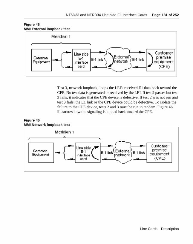
NT5D33 and NTRB34 Line-side E1 Interface Cards Page 181 of 252
the t test and he 6
Figure 45MMI External loopback test
Test 3, network loopback, loops the LEI's received E1 data back towardCPE. No test data is generated or received by the LEI. If test 2 passes bu3 fails, it indicates that the CPE device is defective. If test 2 was not run test 3 fails, the E1 link or the CPE device could be defective. To isolate tfailure to the CPE device, tests 2 and 3 must be run in tandem. Figure 4illustrates how the signaling is looped back toward the CPE.
Figure 46MMI Network loopback test
Line Cards Description
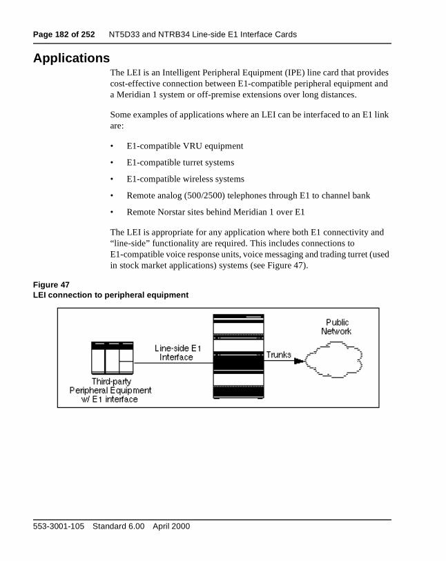
Page 182 of 252 NT5D33 and NTRB34 Line-side E1 Interface Cards
es and
link
d
used
ApplicationsThe LEI is an Intelligent Peripheral Equipment (IPE) line card that providcost-effective connection between E1-compatible peripheral equipment a Meridian 1 system or off-premise extensions over long distances.
Some examples of applications where an LEI can be interfaced to an E1are:
• E1-compatible VRU equipment
• E1-compatible turret systems
• E1-compatible wireless systems
• Remote analog (500/2500) telephones through E1 to channel bank
• Remote Norstar sites behind Meridian 1 over E1
The LEI is appropriate for any application where both E1 connectivity an“line-side” functionality are required. This includes connections to E1-compatible voice response units, voice messaging and trading turret (in stock market applications) systems (see Figure 47).
Figure 47LEI connection to peripheral equipment
553-3001-105 Standard 6.00 April 2000
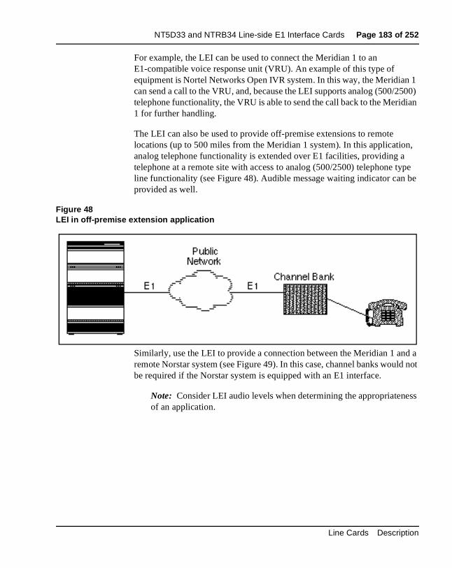
NT5D33 and NTRB34 Line-side E1 Interface Cards Page 183 of 252
1 500) ian
n, ype be
d a d not
ss
For example, the LEI can be used to connect the Meridian 1 to an E1-compatible voice response unit (VRU). An example of this type of equipment is Nortel Networks Open IVR system. In this way, the Meridiancan send a call to the VRU, and, because the LEI supports analog (500/2telephone functionality, the VRU is able to send the call back to the Merid1 for further handling.
The LEI can also be used to provide off-premise extensions to remote locations (up to 500 miles from the Meridian 1 system). In this applicatioanalog telephone functionality is extended over E1 facilities, providing atelephone at a remote site with access to analog (500/2500) telephone tline functionality (see Figure 48). Audible message waiting indicator canprovided as well.
Figure 48LEI in off-premise extension application
Similarly, use the LEI to provide a connection between the Meridian 1 anremote Norstar system (see Figure 49). In this case, channel banks woulbe required if the Norstar system is equipped with an E1 interface.
Note: Consider LEI audio levels when determining the appropriateneof an application.
Line Cards Description
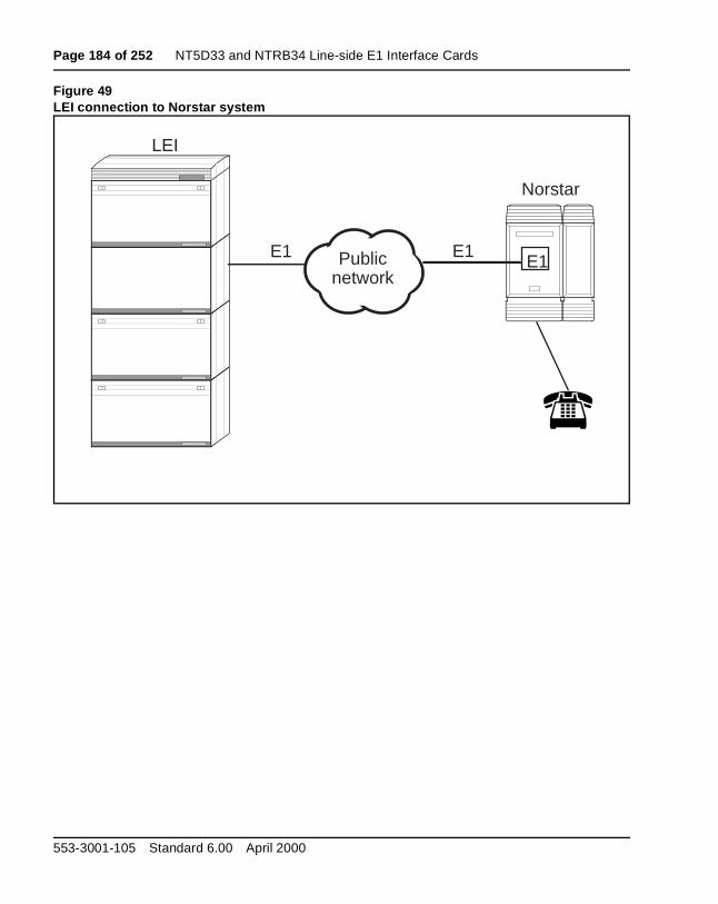
Page 184 of 252 NT5D33 and NTRB34 Line-side E1 Interface Cards
Figure 49LEI connection to Norstar system
E1
Norstar
E1
LEI
Public network
E1
553-3001-105 Standard 6.00 April 2000
Page 185 of 252
192
NT5D60AA CLASS Modem Card (XCMC)Content list
The following are the topics in this section:
• Introduction 186
• Physical description 186
• Functional description 186
• Electrical specifications 190
• Data transmission specifications 190
• Power requirements 190
• Environmental specifications 190
• Configuration 190
• Software service changes 191
Reference listThe following are the references in this section:
• X11 Features and Services (553-3001-306)
• X11 Administration (553-3001-311)
Line Cards Description
Page 186 of 252 NT5D60AA CLASS Modem Card (XCMC)
ta log
to
ting led, test l the ED uch ed.
ral 2 ems
IntroductionThe NT5D60AA CLASS Modem card supports the Custom Local Area Signaling Services (CLASS) feature. The CLASS Modem card receives Calling Number and Calling Name Delivery (CND) data and time/date dafrom the system and transmits it to a line port, such as a port on an AnaLine card, which delivers the CND data to a CLASS telephone set whenpresenting the set with a new call.
For information about the CLASS: Calling Number and Name Delivery feature, please refer to the X11 Features and Services (553-3001-306). For administration and maintenance commands, see theX11 Administration (553-3001-311).
Physical descriptionCLASS Modem cards are housed in NT8D37 Intelligent Peripheral Equipment (IPE) Modules.
The CLASS modem card circuitry is mounted on a 31.75 cm by 25.40 cm(12.5 in. by 10 in.) double-sided printed circuit board. The card connectsthe backplane through a 160-pin edge connector.
The faceplate of the CLASS modem card is equipped with a red light emitdiode (LED) that lights when the card is disabled. When the card is instalthe LED remains lit for two to five seconds as a self-test runs. If the self-completes successfully, the LED flashes three times and remains lit unticard is configured and enabled in software, then the LED goes out. If the Ldoes not follow the pattern described or operates in any other manner (sas continually flashing or remaining weakly lit), the card should be replac
Functional descriptionThe CLASS Modem card is designed to plug into any one of the periphecard slots of the IPE module. The CLASS modem card supports up to 3transmit-only modem resources, using a DS30X interface. Up to 255 modmay be configured per system.
553-3001-105 Standard 6.00 April 2000
NT5D60AA CLASS Modem Card (XCMC) Page 187 of 252
an e
uffer
ASS
ded
he
m
t is 0 The or
ion of
The CND transmission process begins with the system software sendinginitiating message to the CLASS Modem card indicating the length of thCND information and the type of the CND information flow to be transmitted. In response, the CLASS Modem card assigns a message bto capture the CND information from the system software.
System software then sends the CND information to the CLASS Modemcard, one byte at a time, where it is stored in the message buffer. If the CLModem card receives more bytes than were specified in the initiating message, then the additional bytes will be discarded and will not be incluin the CND memory buffer.
Once all of the CND information has been stored in the memory buffer, tCLASS Modem card begins transmission when requested by the systemsoftware. Data is sent one ASCII character at a time. The CLASS Modecard inserts a start and stop bit to each ASCII character sent.
The transmission of the calling party name/number to the terminating seaccomplished via asynchronous FSK simplex-mode transmission at 120bits/second over a 2-wire loop, in accordance with the Bell 202 standard.transmission is implemented by the appropriate PCM equivalent of 12002200 Hz.
Upon completion of transmitting the CND data, the CLASS Modem cardsends a message to the system software to indicate successful transmissthe CND data.
Line Cards Description
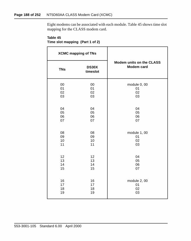
Page 188 of 252 NT5D60AA CLASS Modem Card (XCMC)
slot
Eight modems can be associated with each module. Table 45 shows timemapping for the CLASS modem card.Table 45Time slot mapping (Part 1 of 2)
XCMC mapping of TNs
Modem units on the CLASS Modem card
TNsDS30X
timeslot
00010203
00010203
module 0, 00010203
04050607
04050607
04050607
08091011
08091011
module 1, 00010203
12131415
12131415
04050607
16171819
16171819
module 2, 00010203
553-3001-105 Standard 6.00 April 2000
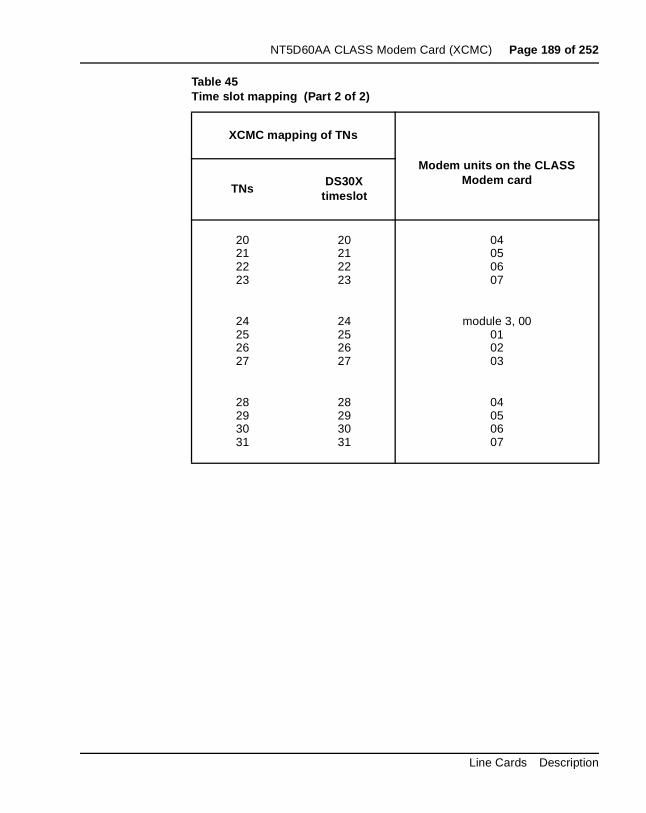
NT5D60AA CLASS Modem Card (XCMC) Page 189 of 252
20212223
20212223
04050607
24252627
24252627
module 3, 00010203
28293031
28293031
04050607
Table 45Time slot mapping (Part 2 of 2)
XCMC mapping of TNs
Modem units on the CLASS Modem card
TNsDS30X
timeslot
Line Cards Description

Page 190 of 252 NT5D60AA CLASS Modem Card (XCMC)
.
es.
.
or and ce.
Electrical specificationsThis section lists the electrical characteristic of the CLASS modem card
Data transmission specificationsTable 46 provides specifications for the 32 transmit-only modem resourc
The CLASS modem card has no direct connection to the Public Network
Power requirementsThe CLASS modem card requires less than 1.0 Amps of +5V dc ± 1% supply supplied by the power converter in the IPE shelf.
Environmental specificationsTable 47 shows the environmental specifications of the card.
ConfigurationThe NT5D60AA CLASS Modem card has no user-configurable jumpersswitches. The card derives its address from its position in the backplanereports that information back to the Meridian 1 CPU via the Cardlan interfa
Table 46CLASS modem card—data transmission electrical characteristics
Characteristics Description
Units per card 32 transmit only modem resources
Transmission rate 1200 ± 12 baud
Table 47CLASS modem card—environmental specifications
Parameter Specifications
Operating temperature 0° C to +65° C (+32 ° F to +149 ° F)
Operating humidity 5 to 95% RH (non-condensing)
Storage temperature -50° C to +70° C (-58 ° F to +158 ° F)
553-3001-105 Standard 6.00 April 2000
NT5D60AA CLASS Modem Card (XCMC) Page 191 of 252
es ) be nd
Software service changesOn systems which are equipped with either CNUMB or CNAME packag(packages 332 and 333 respectively), up to 255 CLASS Modem (CMODunits can be configured in LD 13, and analog (500/2500) telephones canassigned as CLASS sets in LD 10 by assigning them CNUS, or CNUA aCNAA class of service. See the X11 Administration (553-3001-311) for LD 10 and LD 13 service change instructions.
Line Cards Description

Page 192 of 252 NT5D60AA CLASS Modem Card (XCMC)
553-3001-105 Standard 6.00 April 2000
Page 193 of 252
208
NT8D02 Digital Line CardContent list
The following are the topics in this section:
• Introduction 194
• Physical description 194
• Functional description 196
• Card interfaces 198
• Digital line interfaces 198
• Card control functions 199
• Circuit power 200
• Electrical specifications 201
• Digital line interface specifications 201
• Power requirements 202
• Foreign and surge voltage protections 202
• Environmental specifications 203
• Connector pin assignments 203
• Configuration 206
• Jumper and switch settings 206
• Software service changes 206
Line Cards Description
Page 194 of 252 NT8D02 Digital Line Card
) 16
ital inal
t
to
ed e uns.
ED any ard
Reference listThe following are the references in this section:
• System Installation Procedures (553-3001-210)
• X11 Administration (553-3001-311)
IntroductionThe NT8D02 Digital Line Card is an intelligent peripheral equipment (IPEdevice that can be installed in either the NT8D37 IPE Module. It providesvoice and 16 data communication links between a Meridian 1 switch andmodular digital telephones.
The digital line card supports voice only or simultaneous voice and dataservice over a single twisted pair of standard telephone wiring. When a digtelephone is equipped with the data option, an asynchronous ASCII termor personal computer acting like an asynchronous ASCII terminal can beconnected to the system through the digital telephone.
Physical descriptionDigital line cards are housed in NT8D37 Intelligent Peripheral Equipmen(IPE) Modules (up to 16 cards).
The digital line card circuitry is mounted on a 31.75 cm by 25.40 cm (12.5 in. by 10 in.) double-sided printed circuit board. The card connectsthe backplane through a 160-pin edge connector.
The faceplate of the digital line card (see Figure 50) is equipped with a rlight emitting diode (LED) that lights when the card is disabled. When thcard is installed, the LED remains lit for two to five seconds as a self-test rIf the self-test completes successfully, the LED flashes three times and remains lit until the card is configured and enabled in software, then the Lgoes out. If the LED does not follow the pattern described or operates inother manner (such as continually flashing or remaining weakly lit), the cshould be replaced.
553-3001-105 Standard 6.00 April 2000
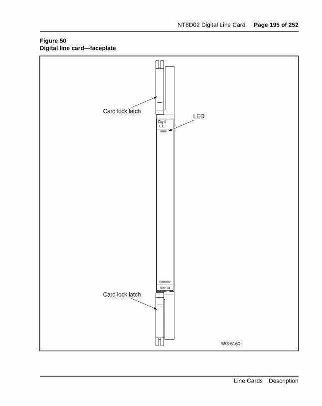
NT8D02 Digital Line Card Page 195 of 252
Figure 50Digital line card—faceplate
553-6160
DgtlLC
NT8D02
Rlse 04
Card lock latch
Card lock latch
LED
Line Cards Description
Page 196 of 252 NT8D02 Digital Line Card
ch m a
the gital
e
Functional descriptionThe digital line card is equipped with 16 identical digital line interfaces. Eainterface provides a multiplexed voice, data, and signaling path to and frodigital terminal (telephone) over a 2-wire full duplex 512 kHz time compression multiplexed (TCM) digital link. Each digital telephone and associated data terminal is assigned a separate terminal number (TN) insystem database, giving a total of 32 addressable units per card. The diline card supports Nortel Networks’ Meridian Digital Telephone.
Figure 51 shows a block diagram of the major functions contained on thdigital line card. Each of these functions are described on the following pages.
553-3001-105 Standard 6.00 April 2000
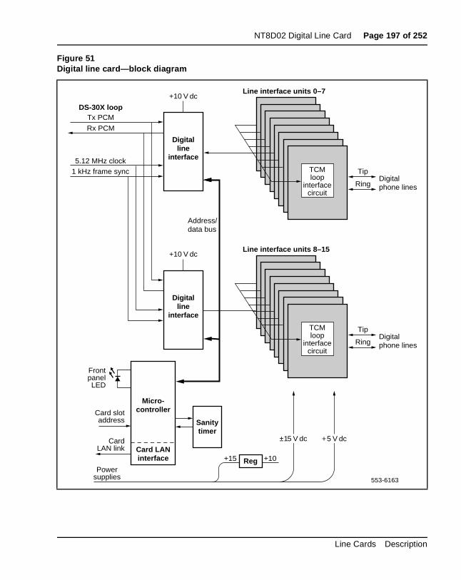
NT8D02 Digital Line Card Page 197 of 252
Figure 51Digital line card—block diagram
Digitalline
interface
Micro-controller
5.12 MHz clock
Tx PCMDS-30X loop
CardLAN link
Powersupplies
FrontpanelLED
Card LANinterface
TipTCMloop
interfacecircuit
Digitalphone lines
Line interface units 0–7
Line interface units 8–15
Ring
TipTCMloop
interfacecircuit
Digitalphone linesRing
Rx PCM
1 kHz frame sync
Card slotaddress Sanity
timer
553-6163
Digitalline
interface
+5 V dc
+10 V dc
±15 V dc
Reg+15 +10
+10 V dc
Address/data bus
Line Cards Description
Page 198 of 252 NT8D02 Digital Line Card
and d in
. ese e
d to
m nd
e r
ts work its the X
uit.
Card interfacesThe digital line card passes voice, data, and signaling over DS-30X loopsmaintenance data over the card LAN link. These interfaces are discussedetail in the section “Intelligent peripheral equipment” on page 17.
Digital line interfacesThe digital line interface contains two digital line interface circuits (DLIC)Each digital line interface circuit provides eight identical and individuallyconfigurable voice and data interfaces to eight digital telephone lines. Thlines carry multiplexed PCM voice, data, and signaling information as timcompression multiplexed (TCM) loops. Each TCM loop can be connectea Nortel Networks M2xxx, M39xx, or Aries digital telephone set.
The purpose of each digital line interface circuit is to demultiplex data frothe DS-30X Tx channel into eight integrated voice and data bitstreams atransmit those bitstreams as Bi-Polar Return to Zero, Alternate Mark Inversion (BPRZ-AMI) data to the eight TCM loops. They also do the opposite: receive eight BPRZ-AMI bitstreams from the TCM loops and multiplex them onto the DS-30X Rx channel. The two digital line interfaccircuits together perform the multiplexing and demultiplexing functions fothe 16 digital telephone lines.
The digital line interface circuits also contain signaling and control circuithat establish, supervise, and take down call connections. These circuits with the on-card microcontroller to operate the digital line interface circuduring calls. The circuits receive outgoing call signaling messages from CP and return incoming call status information to the CP over the DS-30network loop.
TCM loop interface circuitEach digital phone line terminates on the digital line card at a TCM loopinterface circuit. The circuit provides transformer coupling and foreign voltage protection between the TCM loop and the digital line interface circIt also provides battery voltage for the digital telephone set.
553-3001-105 Standard 6.00 April 2000
NT8D02 Digital Line Card Page 199 of 252
card op d
ine dc
he
on ard
he
e
To prevent undesirable side effects from occurring when the TCM loop interface cannot provide the proper signals on the digital phone line, the microcontroller can remove the ±15 V dc power supply from the TCM lointerfaces. This happens when either the microcontroller gets a commanfrom the NT8D01 controller card to shut down the channel or the digital lcard detects a loss of the 1 KHz frame synchronization signal. The ±15 Vpower supply signal is removed from all 16 TCM loop interface units at tsame time.
Each TCM loop interface circuit can service loops up to 3500 ft. in lengthwhen using 24-gauge wire. They allow for a maximum AC signal loss of15.5 dB at 256 KHz and a maximum DC loop resistance of 210 ohms.
Card control functionsControl functions are provided by a microcontroller and a Card LAN link the digital line card. A sanity timer is provided to automatically reset the cif the microcontroller stops functioning for any reason.
MicrocontrollerThe digital line card contains a microcontroller that controls the internal operation of the card and the serial card LAN link to the controller card. Tmicrocontroller controls the following:
— reporting to the CE CP via the card LAN link:
• card identification (card type, vintage, and serial number)
• firmware version
• self-test status
• programmed configuration status
— receipt and implementation of card configuration:
• programming of the digital line interfaces
• enabling/disabling of individual units or entire card
• programming of loop interface control circuits for administration of lininterface unit operation
• maintenance diagnostics
Line Cards Description
Page 200 of 252 NT8D02 Digital Line Card
ard
e it
ne loop
The microcontroller also controls the front panel LED when the card is enabled or disabled by instructions from the NT8D01 controller card.
Card LAN interfaceMaintenance data is exchanged with the common equipment CP over adedicated asynchronous serial network called the Card LAN link. The CLAN link is described in the section “Intelligent peripheral equipment” onpage 17.
Sanity timerThe digital line card also contains a sanity timer that resets the microcontroller if program control is lost. The microcontroller must servicthe sanity timer every 1.2 seconds. If the timer is not properly serviced, times out and causes the microcontroller to be hardware reset.
Circuit powerThe +15 V dc input is regulated down to +10 V dc for use by the digital liinterface circuits. The ±15.0 V dc inputs to the card are used to power the interface circuits.
553-3001-105 Standard 6.00 April 2000
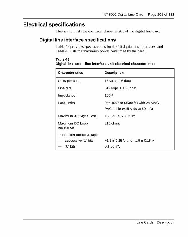
NT8D02 Digital Line Card Page 201 of 252
Electrical specificationsThis section lists the electrical characteristic of the digital line card.
Digital line interface specificationsTable 48 provides specifications for the 16 digital line interfaces, and Table 49 lists the maximum power consumed by the card.
Table 48Digital line card—line interface unit electrical characteristics
Characteristics Description
Units per card 16 voice, 16 data
Line rate 512 kbps ± 100 ppm
Impedance 100¾
Loop limits 0 to 1067 m (3500 ft.) with 24 AWG
PVC cable (±15 V dc at 80 mA)
Maximum AC Signal loss 15.5 dB at 256 KHz
Maximum DC Loop resistance
210 ohms
Transmitter output voltage:
— successive “1” bits
— “0” bits
+1.5 ± 0.15 V and –1.5 ± 0.15 V
0 ± 50 mV
Line Cards Description
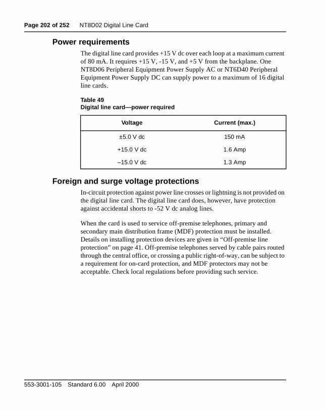
Page 202 of 252 NT8D02 Digital Line Card
ent
l ital
on
uted t to
Power requirementsThe digital line card provides +15 V dc over each loop at a maximum currof 80 mA. It requires +15 V, -15 V, and +5 V from the backplane. One NT8D06 Peripheral Equipment Power Supply AC or NT6D40 PeripheraEquipment Power Supply DC can supply power to a maximum of 16 digline cards.
Foreign and surge voltage protectionsIn-circuit protection against power line crosses or lightning is not providedthe digital line card. The digital line card does, however, have protectionagainst accidental shorts to -52 V dc analog lines.
When the card is used to service off-premise telephones, primary and secondary main distribution frame (MDF) protection must be installed. Details on installing protection devices are given in “Off-premise line protection” on page 41. Off-premise telephones served by cable pairs rothrough the central office, or crossing a public right-of-way, can be subjeca requirement for on-card protection, and MDF protectors may not be acceptable. Check local regulations before providing such service.
Table 49Digital line card—power required
Voltage Current (max.)
±5.0 V dc 150 mA
+15.0 V dc 1.6 Amp
–15.0 V dc 1.3 Amp
553-3001-105 Standard 6.00 April 2000
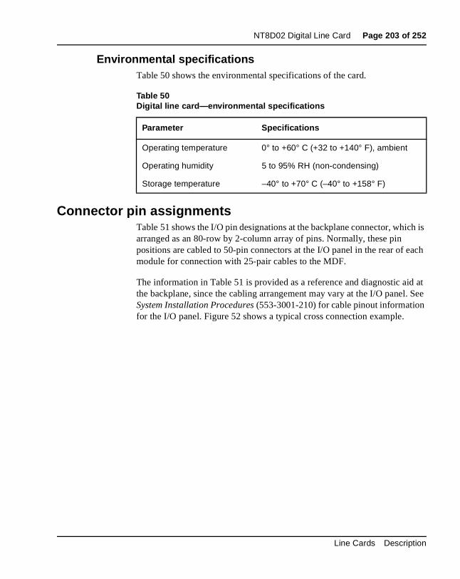
NT8D02 Digital Line Card Page 203 of 252
ch is
ach
d at . See
Environmental specificationsTable 50 shows the environmental specifications of the card.
Connector pin assignmentsTable 51 shows the I/O pin designations at the backplane connector, whiarranged as an 80-row by 2-column array of pins. Normally, these pin positions are cabled to 50-pin connectors at the I/O panel in the rear of emodule for connection with 25-pair cables to the MDF.
The information in Table 51 is provided as a reference and diagnostic aithe backplane, since the cabling arrangement may vary at the I/O panelSystem Installation Procedures (553-3001-210) for cable pinout informationfor the I/O panel. Figure 52 shows a typical cross connection example.
Table 50Digital line card—environmental specifications
Parameter Specifications
Operating temperature 0° to +60° C (+32 to +140° F), ambient
Operating humidity 5 to 95% RH (non-condensing)
Storage temperature –40° to +70° C (–40° to +158° F)
Line Cards Description
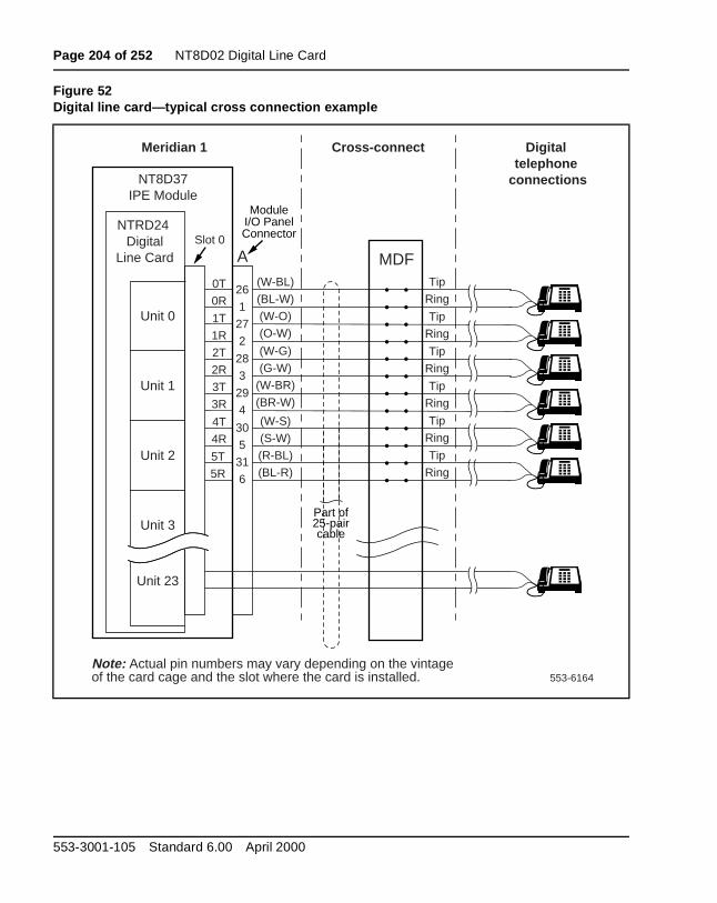
Page 204 of 252 NT8D02 Digital Line Card
Figure 52Digital line card—typical cross connection example
553-6164
NT8D37IPE Module
Slot 0NTRD24
DigitalLine Card
(W-BL)
(BL-W)
(W-O)
(O-W)
0T
0R
1T
1R
26
1
27
2
Meridian 1 Cross-connect Digital telephone
connections
A MDFTip
Ring
Tip
Ring
Tip
Ring
Tip
Ring
(W-G)
(G-W)
(W-BR)
(BR-W)
28
3
29
4(W-S)
(S-W)
(R-BL)
(BL-R)
4T
4R
5T
5R
2T
2R
3T
3R
30
5
31
6
Tip
Ring
Note: Actual pin numbers may vary depending on the vintage of the card cage and the slot where the card is installed.
ModuleI/O PanelConnector
Part of25-paircable
Tip
Ring
Unit 0
Unit 23
Unit 1
Unit 2
Unit 3
553-3001-105 Standard 6.00 April 2000
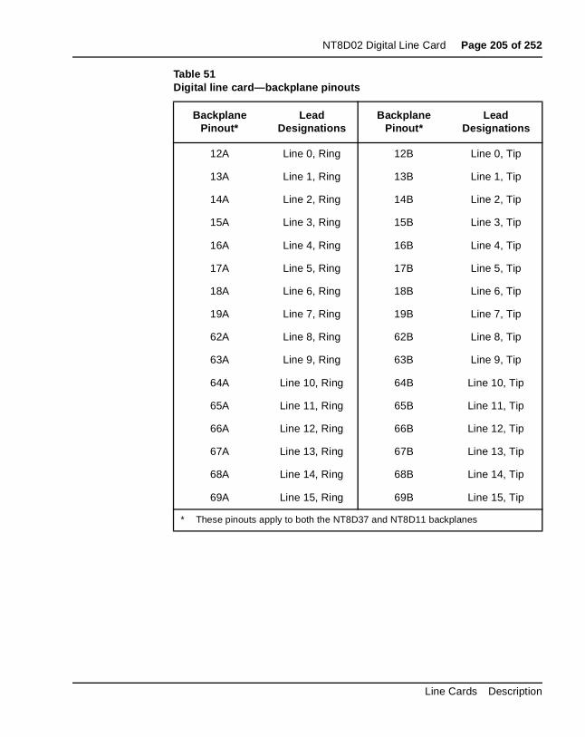
NT8D02 Digital Line Card Page 205 of 252
Table 51Digital line card—backplane pinouts
Backplane Pinout*
Lead Designations
Backplane Pinout*
Lead Designations
12A Line 0, Ring 12B Line 0, Tip
13A Line 1, Ring 13B Line 1, Tip
14A Line 2, Ring 14B Line 2, Tip
15A Line 3, Ring 15B Line 3, Tip
16A Line 4, Ring 16B Line 4, Tip
17A Line 5, Ring 17B Line 5, Tip
18A Line 6, Ring 18B Line 6, Tip
19A Line 7, Ring 19B Line 7, Tip
62A Line 8, Ring 62B Line 8, Tip
63A Line 9, Ring 63B Line 9, Tip
64A Line 10, Ring 64B Line 10, Tip
65A Line 11, Ring 65B Line 11, Tip
66A Line 12, Ring 66B Line 12, Tip
67A Line 13, Ring 67B Line 13, Tip
68A Line 14, Ring 68B Line 14, Tip
69A Line 15, Ring 69B Line 15, Tip
* These pinouts apply to both the NT8D37 and NT8D11 backplanes
Line Cards Description
Page 206 of 252 NT8D02 Digital Line Card
pers per
and
e
ConfigurationThis section outlines the procedures for configuring the switches and jumon the NT8D02 Digital Line Card and configuring the system software toproperly recognize the card. Figure 53 shows where the switches and jumblocks are located on this board.
Jumper and switch settingsThe NT8D02 Digital Line Card has no user-configurable jumpers or switches. The card derives its address from its position in the backplanereports that information back to the Meridian 1 CP via the LAN Link interface.
Software service changesVoice and data ports are configured using the Meridian Digital TelephonAdministration program (LD 11). See the X11 Administration (553-3001-311) for LD 11 service change instructions.
553-3001-105 Standard 6.00 April 2000
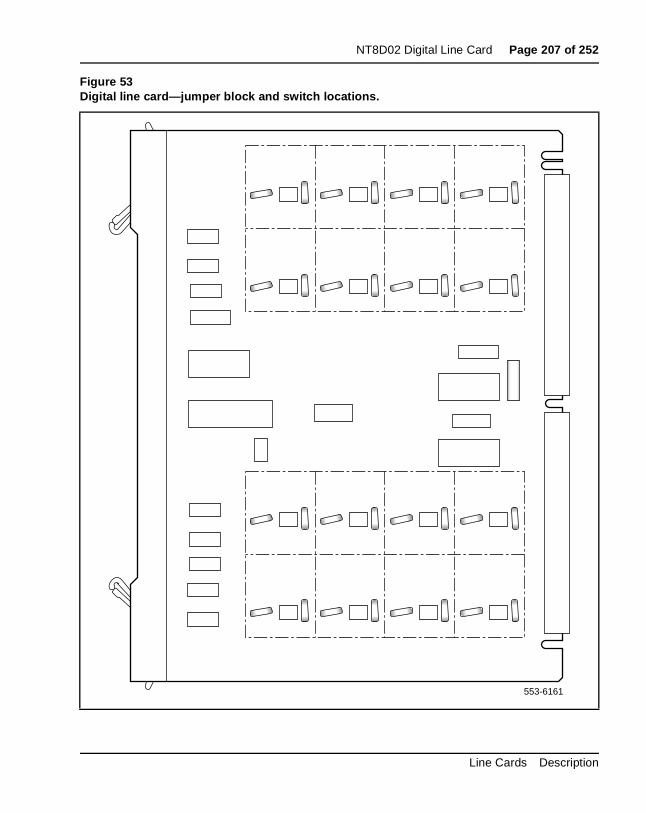
NT8D02 Digital Line Card Page 207 of 252
Figure 53Digital line card—jumper block and switch locations.
553-6161
Line Cards Description
Page 208 of 252 NT8D02 Digital Line Card
553-3001-105 Standard 6.00 April 2000
Page 209 of 252
226
NT8D09 Analog Message Waiting Line Card
Content listThe following are the topics in this section:
• Introduction 210
• Physical description 211
• Functional description 213
• Card interfaces 213
• Line interface units 213
• Card control functions 215
• Circuit power 215
• Electrical specifications 217
• Analog line interface 217
• Power requirements 219
• Foreign and surge voltage protections 220
• Environmental specifications 220
• Connector pin assignments 221
• Configuration 224
• Jumper and switch settings 224
• Software service changes 224
Line Cards Description
Page 210 of 252 NT8D09 Analog Message Waiting Line Card
ral talk e This DC.
ng, e f a
d.
Reference listThe following are the references in this section:
• System Installation Procedures (553-3001-210)
• X11 Administration (553-3001-311)
IntroductionThe NT8D09 Analog Message Waiting Line Card is an intelligent peripheequipment (IPE) line card that can be installed in either the NT8D37 IPEmodule (up to 16 cards). The analog message waiting line card providesbattery and signaling for up to 16 regular 2-wire common battery analog(500/2500) telephones and key telephone equipment. The card can alsoconnect a high-voltage, low-current feed to each line to light the messagwaiting lamp on telephones equipped with the Message Waiting feature. voltage is provided by the NT6D40 Peripheral Equipment Power Supply,
Cards later than vintage NT8D09AK support µ-Law and A-Law compandiand provide a 2 dB transmission profile change. The transmission changimproves performance on long lines, particularly for lines used outside osingle-building environment.
Note: If a modem is connected to a port on the message waiting linecard, that port should not be defined in software (LD 10) as having message waiting capabilities. Otherwise, the modem will be damage
553-3001-105 Standard 6.00 April 2000
NT8D09 Analog Message Waiting Line Card Page 211 of 252
ry is ard.
h a ) d a e
is
ED d in
or
Physical descriptionThe analog message waiting line card mounts in any IPE slot. The circuitmounted on a 31.75 cm. by 25.40 cm (12.5 in. by 10 in.) printed circuit bo
The analog message waiting line card connects to the backplane throug160-pin edge connector. The backplane is cabled to the input/output (I/Opanel that then connects to the main distribution frame (MDF), also callecross-connect terminal through 25-pair cables. Telephones connect to thcard through the MDF. See System Installation Procedures (553-3001-210) for termination and cross-connect information.
The faceplate of the analog message waiting line card (see Figure 54) isequipped with a red light emitting diode (LED) that lights when the card disabled. When the card is installed, the LED remains lit for two to five seconds as a self-test runs. If the self-test completes successfully, the Lflashes three times and remains lit until the card is configured and enablesoftware; then the LED goes out. If the LED does not follow the pattern described or operates in any other manner (such as continually flashingremaining weakly lit), the card should be replaced. Figure 54 shows an NT8D09 card faceplate.
Line Cards Description
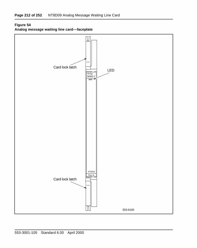
Page 212 of 252 NT8D09 Analog Message Waiting Line Card
Figure 54Analog message waiting line card—faceplate
553-6165
AnlgM/WLC
NT8D09
Rlse 0x
Card lock latch
Card lock latch
LED
553-3001-105 Standard 6.00 April 2000
NT8D09 Analog Message Waiting Line Card Page 213 of 252
e in the
ver ces
ently
al to t nd
ach on
ling
for
ses
in r the
Functional descriptionFigure 55 shows a block diagram of the major functions contained on thanalog message waiting line card. Each of these functions are described following sections.
Card interfacesThe analog message waiting line card passes voice and signaling data oDS-30X loops and maintenance data over the card LAN link. These interfaare discussed in “Intelligent peripheral equipment” on page 17.
Line interface unitsThe analog message waiting line card contains 16 identical and independconfigurable line interface units (also referred to as circuits). Each unit provides 600-ohm impedance matching and a balance network in a signtransformer/analog hybrid circuit. Circuits are also provided in each unit apply the ringing voltage onto the line synchronized to the ringing currenzero crossing. Signal detection circuits monitor on-hook/off-hook status aswitchhook flash detection. Four codecs are provided to perform A/D and D/A conversion of line analog voiceband signals to digital PCM signals. Ecodec supports four line interface units. The following features are commto all units on the card:
• transmission and reception of scan and signaling device (SSD) signamessages over a DS30X signaling channel in A10 format
• loopback of SSD messages and pulse code modulation (PCM) signalsdiagnostic purposes
• correct initialization of all features, as configured in software, at power-up
• direct reporting of digits dialed (500 telephones) by collecting dial pul
• connection of –150 V dc at 1 Hz to activate message waiting lamps two telephone sets in parallel. The two sets must be the same type oneon series resistor in each set must be 54 K¾ or greater.
• lamp status detection (will not detect a failure of either lamp when operating in parallel)
• disabling and enabling of selected units for maintenance
• 40 mA to sets with short circuit protection
Line Cards Description
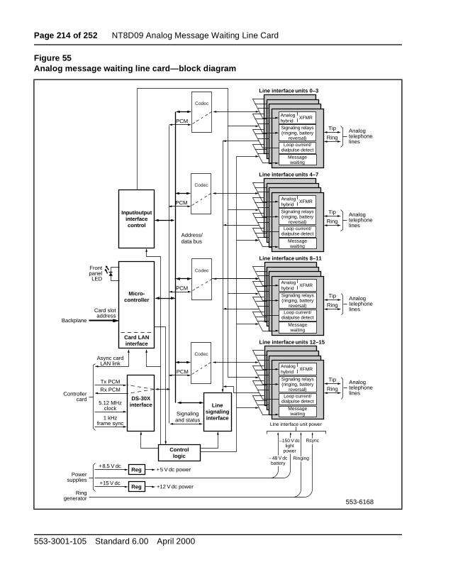
Page 214 of 252 NT8D09 Analog Message Waiting Line Card
Figure 55Analog message waiting line card—block diagram
Input/outputinterfacecontrol
Micro-controller
DS-30Xinterface5.12 MHz
clock
Tx PCM
Async cardLAN link
FrontpanelLED
Card LANinterface
Line interface unit power
Rx PCM
1 kHzframe sync
Card slotaddress
Backplane
Controllercard
Linesignalinginterface
Controllogic
Reg
Signalingand status
Address/data bus
553-6168
Powersupplies
Ringgenerator
–150 V dclight
power
+8.5 V dc+5 V dc power
Reg+15 V dc
+12 V dc power
Ringing– 48 V dcbattery
Rsync
XFMR
Signaling relays(ringing, battery
reversal)
Line interface units 0–3
Tip
RingAnalogtelephonelines
Loop current/dialpulse detect
Messagewaiting
XFMR
Signaling relays(ringing, battery
reversal)
Line interface units 4–7
Tip
RingAnalogtelephonelines
Loop current/dialpulse detect
Messagewaiting
XFMR
Signaling relays(ringing, battery
reversal)
Line interface units 8–11
Tip
RingAnalogtelephonelines
Loop current/dialpulse detect
Messagewaiting
XFMR
Signaling relays(ringing, battery
reversal)
Line interface units 12–15
Tip
RingAnalogtelephonelines
Loop current/dialpulse detect
Messagewaiting
Analoghybrid
Analoghybrid
Analoghybrid
Analoghybrid
PCM
Codec
PCM
Codec
PCM
Codec
PCM
Codec
553-3001-105 Standard 6.00 April 2000
NT8D09 Analog Message Waiting Line Card Page 215 of 252
, rd.
trols ller
ish, ng
ic he its.
Card control functionsControl functions are provided by a microcontroller, a card LAN interfaceand signaling and control circuits on the analog message waiting line ca
MicrocontrollerThe analog message waiting line card contains a microcontroller that conthe internal operation of the card and the serial card LAN link to the controcard. The microcontroller controls the following:
• reporting to the CE CP via the card LAN link:
— card identification (card type, vintage, and serial number)
— firmware version
— self-test status
— programmed configuration status
• receipt and implementation of card configuration:
— programming of the codecs
— enabling/disabling of individual units or entire card
— programming of input/output interface control circuits for administration of line interface unit operation
— enabling/disabling of an interrupted dial tone to indicate call waiting
— maintenance diagnostics
— transmission loss levels
Signaling and controlThe signaling and control portion of the card provides circuits that establsupervise, and take down call connections. These circuits work with thesystem CP to operate the line interface circuits during calls. The circuitsreceive outgoing call signaling messages from the CP and return incomicall status information over the DS-30X network loop.
Circuit powerThe +8.5 V dc input is regulated down to +5 V dc for use by the digital logcircuits. All other power to the card is used by the line interface circuits. T+15.0 V dc input is regulated down to +12 V dc to power the analog circuThe –48.0 V dc input is for telephone set battery.
Line Cards Description

Page 216 of 252 NT8D09 Analog Message Waiting Line Card
he nt
e ls to
Ringing power for telephone sets is 86 Vrms ac at 20 Hz on –48 V dc. TRsync signal is used to switch 20 Hz ringing on and off at the zero currecross-over point to lengthen the life of the switching circuits.
Power for lighting the message waiting lights is provided by either the peripheral equipment power supply or the ringing generator. Logic on thmessage waiting line card interrupts the –150 V dc signal at 1 Hz intervaprovide a flashing message waiting light.
553-3001-105 Standard 6.00 April 2000
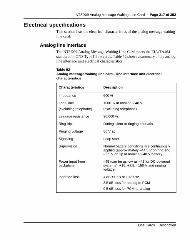
NT8D09 Analog Message Waiting Line Card Page 217 of 252
iting
alog
Electrical specificationsThis section lists the electrical characteristics of the analog message waline card.
Analog line interfaceThe NT8D09 Analog Message Waiting Line Card meets the EIA/TA464 standard for ONS Type II line cards. Table 52 shows a summary of the anline interface unit electrical characteristics.
Table 52Analog message waiting line card—line interface unit electrical characteristics
Characteristics Description
Impedance 600 ¾
Loop limit
(excluding telephone)
1000 ¾ at nominal –48 V
(excluding telephone)
Leakage resistance 30,000 ¾
Ring trip During silent or ringing intervals
Ringing voltage 86 V ac
Signaling Loop start
Supervision Normal battery conditions are continuously applied (approximately –44.5 V on ring and –2.5 V on tip at nominal –48 V battery)
Power input from backplane
–48 (can be as low as –42 for DC-powered systems), +15, +8.5, –150 V and ringing voltage
Insertion loss 4 dB ±1 dB at 1020 Hz
3.5 dB loss for analog to PCM
0.5 dB loss for PCM to analog
Line Cards Description
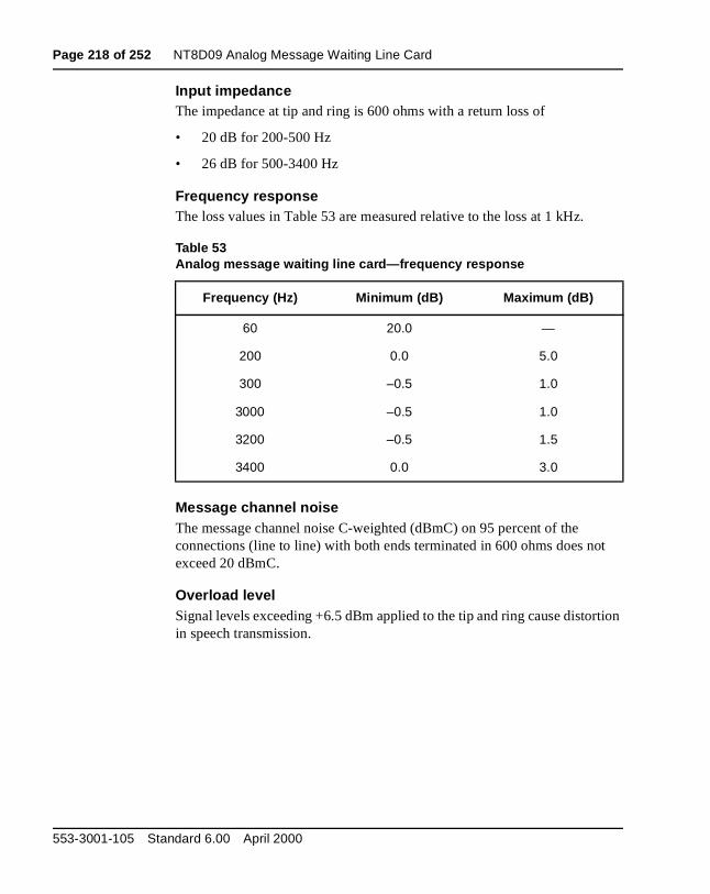
Page 218 of 252 NT8D09 Analog Message Waiting Line Card
t
tion
Input impedanceThe impedance at tip and ring is 600 ohms with a return loss of
• 20 dB for 200-500 Hz
• 26 dB for 500-3400 Hz
Frequency responseThe loss values in Table 53 are measured relative to the loss at 1 kHz.
Message channel noiseThe message channel noise C-weighted (dBmC) on 95 percent of the connections (line to line) with both ends terminated in 600 ohms does noexceed 20 dBmC.
Overload levelSignal levels exceeding +6.5 dBm applied to the tip and ring cause distorin speech transmission.
Table 53Analog message waiting line card—frequency response
Frequency (Hz) Minimum (dB) Maximum (dB)
60 20.0 —
200 0.0 5.0
300 –0.5 1.0
3000 –0.5 1.0
3200 –0.5 1.5
3400 0.0 3.0
553-3001-105 Standard 6.00 April 2000
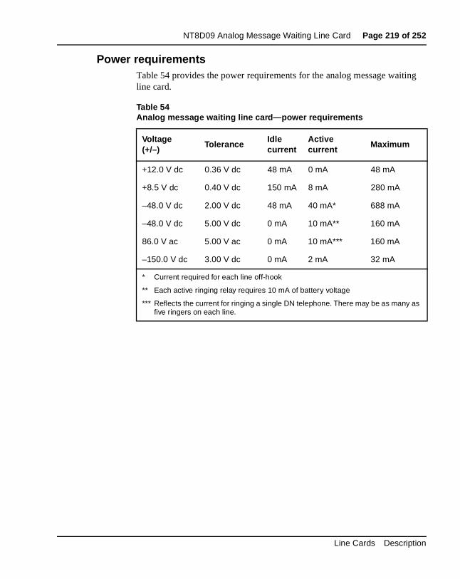
NT8D09 Analog Message Waiting Line Card Page 219 of 252
ng
Power requirementsTable 54 provides the power requirements for the analog message waitiline card.
Table 54Analog message waiting line card—power requirements
Voltage(+/–)
ToleranceIdlecurrent
Activecurrent
Maximum
+12.0 V dc 0.36 V dc 48 mA 0 mA 48 mA
+8.5 V dc 0.40 V dc 150 mA 8 mA 280 mA
–48.0 V dc 2.00 V dc 48 mA 40 mA* 688 mA
–48.0 V dc 5.00 V dc 0 mA 10 mA** 160 mA
86.0 V ac 5.00 V ac 0 mA 10 mA*** 160 mA
–150.0 V dc 3.00 V dc 0 mA 2 mA 32 mA
* Current required for each line off-hook
** Each active ringing relay requires 10 mA of battery voltage
*** Reflects the current for ringing a single DN telephone. There may be as many as five ringers on each line.
Line Cards Description

Page 220 of 252 NT8D09 Analog Message Waiting Line Card
on
e
rs e not
Foreign and surge voltage protectionsIn-circuit protection against power line crosses or lightning is not providedthe analog message waiting line card. When the card is used to service off-premise telephones, primary and secondary MDF protection must beinstalled. Details on installing protection devices are given in “Off-premisline protection” on page 41. Off-premise telephones served by cable pairouted through the central office, or crossing a public right-of-way, can bsubject to a requirement for on-card protection, and MDF protectors maybe acceptable. Check local regulations before providing such service.
Environmental specificationsTable 55 lists the environmental specifications for the analog message waiting line card.
Table 55Analog message waiting line card—environmental specifications
Parameter Specifications
Operating temperature 0° to +60° C (+32 to +140° F), ambient
Operating humidity 5 to 95% RH (noncondensing)
Storage temperature –40° to +70° C (–40° to +158° F)
553-3001-105 Standard 6.00 April 2000
NT8D09 Analog Message Waiting Line Card Page 221 of 252
E o the d to
sage nk
tor is
ach .
d at . See
Connector pin assignmentsThe analog message waiting line card brings the 16 phone lines to the IPbackplane through a 160-pin connector shroud. The backplane is cabled tinput/output (I/O) panel on the rear of the module, which is then connectethe main distribution frame (MDF) by 25-pair cables.
Telephone lines from station equipment cross connect to the analog meswaiting line card at the MDF using a wiring plan similar to that used for trucards. A typical connection example is shown in Figure 56, and Table 56shows the I/O pin designations at the backplane connector. This connecarranged as an 80-row by 2-column array of pins. Normally, these pin positions are cabled to 50-pin connectors at the I/O panel in the rear of emodule for connection with 25-pair cables to the cross-connect terminal
The information in Table 56 is provided as a reference and diagnostic aithe backplane, since the cabling arrangement may vary at the I/O panelSystem Installation Procedures (553-3001-210) for cable pinout informationat the I/O panel.
Line Cards Description

Page 222 of 252 NT8D09 Analog Message Waiting Line Card
Figure 56Analog message waiting line card—typical cross connection example
553-6169
NT8D37IPE Module
Slot 0
NT8D09 MessageWaiting
Line Card0T
0R
1T
1R
26
1
27
2
Meridian 1 Cross-connect OPS or ONStelephone
connectionswith messagewaiting lamps
A MDFTip
Ring
Tip
Ring
Tip
Ring
Tip
Ring
28
3
29
44T
4R
5T
5R
2T
2R
3T
3R
30
5
31
6
Tip
Ring
Note: Actual pin numbers may vary depending on the vintage of the card cage and the slot where the card is installed.
ModuleI/O PanelConnector
Part of25-paircable
Tip
Ring
Unit 0
Unit 15
Unit 1
Unit 2
Unit 3
(W-BL)
(BL-W)
(W-O)
(O-W)
(W-G)
(G-W)
(W-BR)
(BR-W)
(W-S)
(S-W)
(R-BL)
(BL-R)
553-3001-105 Standard 6.00 April 2000
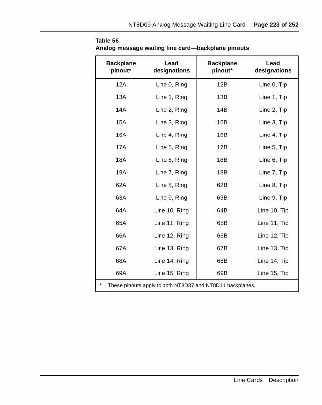
NT8D09 Analog Message Waiting Line Card Page 223 of 252
Table 56Analog message waiting line card—backplane pinouts
Backplane pinout*
Lead designations
Backplane pinout*
Lead designations
12A Line 0, Ring 12B Line 0, Tip
13A Line 1, Ring 13B Line 1, Tip
14A Line 2, Ring 14B Line 2, Tip
15A Line 3, Ring 15B Line 3, Tip
16A Line 4, Ring 16B Line 4, Tip
17A Line 5, Ring 17B Line 5, Tip
18A Line 6, Ring 18B Line 6, Tip
19A Line 7, Ring 18B Line 7, Tip
62A Line 8, Ring 62B Line 8, Tip
63A Line 9, Ring 63B Line 9, Tip
64A Line 10, Ring 64B Line 10, Tip
65A Line 11, Ring 65B Line 11, Tip
66A Line 12, Ring 66B Line 12, Tip
67A Line 13, Ring 67B Line 13, Tip
68A Line 14, Ring 68B Line 14, Tip
69A Line 15, Ring 69B Line 15, Tip
* These pinouts apply to both NT8D37 and NT8D11 backplanes.
Line Cards Description
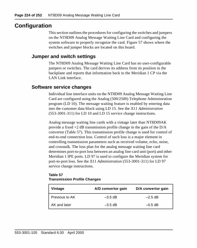
Page 224 of 252 NT8D09 Analog Message Waiting Line Card
pers
the
ble
ne ion ata
l of
se,
ther
ConfigurationThis section outlines the procedures for configuring the switches and jumon the NT8D09 Analog Message Waiting Line Card and configuring the system software to properly recognize the card. Figure 57 shows whereswitches and jumper blocks are located on this board.
Jumper and switch settingsThe NT8D09 Analog Message Waiting Line Card has no user-configurajumpers or switches. The card derives its address from its position in thebackplane and reports that information back to the Meridian 1 CP via theLAN Link interface.
Software service changesIndividual line interface units on the NT8D09 Analog Message Waiting LiCard are configured using the Analog (500/2500) Telephone Administratprogram (LD 10). The message waiting feature is enabled by entering dinto the customer data block using LD 15. See the X11 Administration (553-3001-311) for LD 10 and LD 15 service change instructions.
Analog message waiting line cards with a vintage later than NT8D09AKprovide a fixed +2 dB transmission profile change in the gain of the D/A convertor (Table 57). This transmission profile change is used for controend-to-end connection loss. Control of such loss is a major element in controlling transmission parameters such as received volume, echo, noiand crosstalk. The loss plan for the analog message waiting line card determines port-to-port loss between an analog line card unit (port) and oMeridian 1 IPE ports. LD 97 is used to configure the Meridian system forport-to-port loss. See the X11 Administration (553-3001-311) for LD 97 service change instructions.
Table 57Transmission Profile Changes
Vintage A/D convertor gain D/A convertor gain
Previous to AK –3.5 dB –2.5 dB
AK and later –3.5 dB –0.5 dB
553-3001-105 Standard 6.00 April 2000
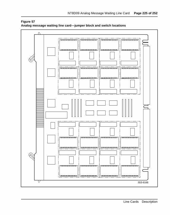
NT8D09 Analog Message Waiting Line Card Page 225 of 252
Figure 57Analog message waiting line card—jumper block and switch locations
553-6166
Line Cards Description

Page 226 of 252 NT8D09 Analog Message Waiting Line Card
553-3001-105 Standard 6.00 April 2000
Page 227 of 252
242
NTRD24 24-Port Digital Line CardContent list
The following are the topics in this section:
• Introduction 228
• Physical description 228
• Engineering guidelines 230
• Functional description 231
• Card interfaces 233
• Digital line interfaces 233
• Card control functions 234
• Circuit power 235
• Engineering guidelines 230
• Digital line interface specifications 236
• Power requirements 237
• Foreign and surge voltage protections 237
• Environmental specifications 237
• Connector pin assignments 238
• Configuration 240
• Backward Compatibility 240
• Jumper and switch settings 240
• Software service changes 241
Line Cards Description
Page 228 of 252 NTRD24 24-Port Digital Line Card
e
t of card 15 are
.
cm ane
ed, e uns.
Reference listThe following reference is in this section:
• System Installation Procedures (553-3001-210)
IntroductionThe NTRD24 24-Port Digital Line Card (EDLC) provides an alternative configuration to the existing NT8D02 16-Port Digital Line Card (XDLC). The EDLC provides 24 voice units and 8 data units. The following Meridian 1 systems support the 24-Port Digital Line Card:
• Option 51C
• Option 61C
• Option 81C
Note: The NTRD24 24-Port Digital Line Card is not supported on thOption 11C or Option 11C Mini.
The card has 24 ports. Sixteen of the ports have one unit for voice. Eighthe ports have two units, one unit for voice and one unit for data. So eachhas a total of 24 ports and 32 units. The port allocation is fixed. Ports 0 -support voice, and ports 16 - 23 support both voice and data. Units 0 - 23configured as voice units, and units 24 - 31 are configured as data units
Physical descriptionThe 24-Port Digital Line card may be equipped in any housing enclosurecapable of supporting Intelligent Peripheral Equipment (IPE).
The 24-Port Digital Line card circuitry is mounted on a 31.75 cm by 25.40 (12.5 in. by 10 in.) printed circuit board. The card connects to the backplthrough a 160-pin edge connector.
The faceplate of the digital line card (see Figure 58) is equipped with a rlight emitting diode (LED) that lights when the card is disabled. When thcard is installed, the LED remains lit for two to five seconds as a self-test r
553-3001-105 Standard 6.00 April 2000
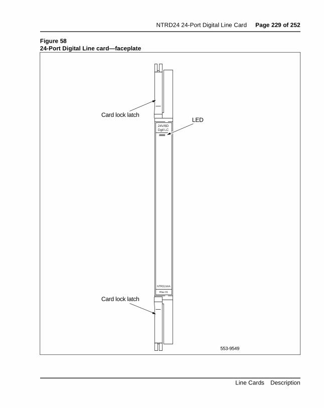
NTRD24 24-Port Digital Line Card Page 229 of 252
Figure 5824-Port Digital Line card—faceplate
553-9549
Card lock latch
Card lock latch
LED24V/8DDgtl LC
NTRD24AA
Rlse 01
Line Cards Description
Page 230 of 252 NTRD24 24-Port Digital Line Card
ED any ard
can
t of r,
l
If the self-test completes successfully, the LED flashes three times and remains lit until the card is configured and enabled in software, then the Lgoes out. If the LED does not follow the pattern described or operates inother manner (such as continually flashing or remaining weakly lit), the cshould be replaced.
Engineering guidelinesNTRD24 cards can require more power than currently installed systemsprovide. For example, the maximum rating of NT8D06 and NT6D40 power units in Meridian 1 IPE shelves will be reached before the full complemenavailable card slots is used. To ensure that each card has enough poweallocate cards in accordance with Table 58.
If a currently installed system has been upgraded, the existing peripherapower units in associated equipment modules were not upgraded, the NTRD24 card placement restrictions in Table 58 also apply.
Table 58NTRD24 card allocation
Power Unit
Type Application Maximum EDLC provisioning
NT8D06 AC 51C, 61C, 81C
Contact your system supplier or your Nortel Networks representative to verify the number of 24-port DLCs and mix of line/trunk cards supported in your IPE module.
NT6D40 DC 51C, 61C, 81C
Contact your system supplier or your Nortel Networks representative to verify the number of 24-port DLCs and mix of line/trunk cards supported in your IPE module.
553-3001-105 Standard 6.00 April 2000
NTRD24 24-Port Digital Line Card Page 231 of 252
ance
o. nd 2 e nits
ay of ice
The type of IPE module used to house the cards may also affect card placement. For installed base upgrades, install NTRD24 cards in accordwith Table 59.
Functional descriptionThe 24-Port Digital Line card is equipped with 24 ports, each capable ofconnecting to any digital telephone selected from the Meridian 1 portfoliEach port provides the capability to support a multiplexed voice, data, asignaling path to and from a digital telephone over a 2-wire full duplex 51kHz time compression multiplexed (TCM) digital link. Each digital telephonis assigned a separate Terminal Number (TN) in the system database. U0-15 are always assigned a class-of-service of VCE for voice-only applications. Units 16-23 are also assigned a VCE class of service, but mbe paired with Units 24-31, which are always allocated a data-only classservice of DTA.This arrangement provides a fixed configuration of 24 voports, 8 of which provide simultaneous voice and data capabilities.
Table 60 shows a block diagram of the major functions contained on the24-Port Digital Line card. Each of these functions are described on the following pages.
Table 59NTRD24 IPE module provisioning
IPE Module Power Cabling Maximum EDLC provisioning
NT8D37BA AC 24 pair See Note 1 for the number of 24-port DLCs located in any of slots 0-15.
NT8D37EC DC 24 pair See Note 1 for the number of 24-port DLCs located in any of slots 0-15.
NT8D37AA AC 16/24 pair See Note 1 for the number of 24-port DLCs located in slots 0, 4, 8, 12.
NT8D37DC DC 16/24 pair See Note 1 for the number of 24-port DLCs located in slots 0, 4, 8, 12.
Note 1: Contact your system supplier or your Nortel Networks representative to verify the number and slot location of 24-port DLCs with a mix of line/trunk cards supported in your IPE module.
Line Cards Description
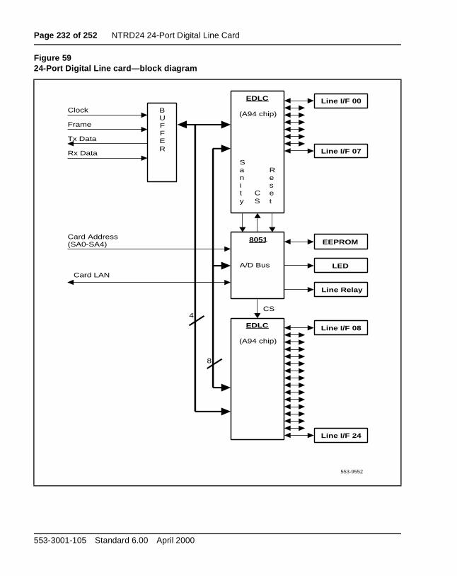
Page 232 of 252 NTRD24 24-Port Digital Line Card
Figure 5924-Port Digital Line card—block diagram
Clock
Frame
Tx Data
Rx Data
Card Address(SA0-SA4)
CS
8051
BUFFER
EDLC
(A94 chip)
Line I/F 00
Line I/F 07
Reset
Sanity
CS
EDLC
(A94 chip)
Line I/F 08
Line I/F 24
Card LAN
EEPROM
Line Relay
LED
4
8
A/D Bus
553-9552
553-3001-105 Standard 6.00 April 2000
NTRD24 24-Port Digital Line Card Page 233 of 252
30X
24 rd.
he
m smit
rm
ts work its the X
is only ixed
M gn ine set.
Card interfacesThe 24-Port Digital Line card passes voice, data, and signaling over DS-loops and maintenance data over the card LAN link.
Digital line interfacesThe 24 digital line interfaces and their corresponding ports on the NTRDare connected by two digital line interface circuits, located on the line caThe digital line interface circuit provides 16 time compression multiplex (TCM) loops for conversion into the DS-30X format. These loops carry multiplexed PCM voice, data, and signaling information as TCM links to tassociated digital telephones.
The purpose of each digital line interface circuit is to demultiplex data frothe DS-30X Tx channel into integrated voice and data bitstreams and tranthose bitstreams as Bi-Polar Return to Zero, Alternate Mark Inversion (BPRZ-AMI) data to the TCM loop. They also do the opposite: receive BPRZ-AMI bitstreams from the TCM loop and multiplex them onto the DS-30X Rx channel. The two digital line interface circuits together perfothe multiplexing and demultiplexing functions for the 24 digital telephonelines.
The digital line interface circuits also contain signaling and control circuithat establish, supervise, and take down call connections. These circuits with the on-card microcontroller to operate the digital line interface circuduring calls. The circuits receive outgoing call signaling messages from CP and return incoming call status information to the CP over the DS-30network loop.
As shown in Figure 3, the configuration of each digital line interface chipsuch that one supports eight integrated voice/data ports plus eight voiceports, and the other chip supports eight voice only ports. The result is a fconfiguration of sixteen voice only ports and eight integrated ports.
TCM loop interface circuitEach digital phone line terminates on the 24-Port Digital Line card at a TCloop interface circuit. The circuit provides transformer coupling and foreivoltage protection (up to 52 volts) between the TCM loop and the digital linterface circuit. It also provides battery voltage for the digital telephone
Line Cards Description
Page 234 of 252 NTRD24 24-Port Digital Line Card
card op d ine dc
he
on set
e r
To prevent undesirable side effects from occurring when the TCM loop interface cannot provide the proper signals on the digital phone line, the microcontroller can remove the ±15 V dc power supply from the TCM lointerfaces. This happens when either the microcontroller gets a commanfrom the Controller card to shut down the channel or the 24-Port Digital Lcard detects a loss of the 1 KHz frame synchronization signal. The ±15 Vpower supply signal is removed from all 24 TCM loop interface units at tsame time.
Each TCM loop interface circuit can service loops up to 3500 ft. in lengthwhen using 24-gauge wire. They allow for a maximum AC signal loss of15.5 dB at 256 KHz and a maximum DC loop resistance of 210 ohms.
Card control functionsControl functions are provided by a microcontroller and a card LAN link the 24-Port Digital Line card. A sanity timer is provided to automatically rethe card if the microcontroller stops functioning for any reason.
MicrocontrollerThe 24-Port Digital Line card contains a microcontroller that manages thinternal operation of the card and the serial card LAN link to the controllecard. The microcontroller controls the following:
• reporting to the CE CP via the card LAN link:
— line card status indication
— card identification (card type, vintage, and serial number)
— firmware version
— self-test status
— programmed configuration status
• receipt and implementation of card configuration:
— programming of the digital line interfaces
— enabling/disabling of individual units or entire card
— programming of loop interface control circuits for administration of line interface unit operation
— maintenance diagnostics
553-3001-105 Standard 6.00 April 2000
NTRD24 24-Port Digital Line Card Page 235 of 252
e
it
rd.
The microcontroller also controls the front panel LED when the card is enabled or disabled by instructions from the associated Controller card.
Card LAN interfaceMaintenance data is exchanged with the common equipment CP over adedicated asynchronous serial network called the card LAN link.
Sanity timerThe 24-Port Digital Line card also contains a sanity timer that resets themicrocontroller if program control is lost. The microcontroller must servicthe sanity timer every 1.2 seconds. If the timer is not properly serviced, times out and resets the microcontroller.
Circuit powerThe ±15.0 V DC inputs to the card are used to power the loop interface circuits. The ±5.0 V DC inputs to the card are used to power the internalcircuitry of the board.
Electrical specificationsThis section lists the electrical characteristic of the 24-Port Digital Line ca
Line Cards Description
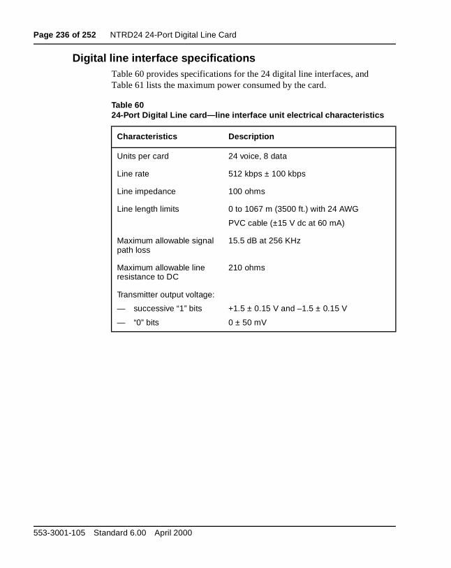
Page 236 of 252 NTRD24 24-Port Digital Line Card
Digital line interface specificationsTable 60 provides specifications for the 24 digital line interfaces, and Table 61 lists the maximum power consumed by the card.
Table 6024-Port Digital Line card—line interface unit electrical characteristics
Characteristics Description
Units per card 24 voice, 8 data
Line rate 512 kbps ± 100 kbps
Line impedance 100 ohms
Line length limits 0 to 1067 m (3500 ft.) with 24 AWG
PVC cable (±15 V dc at 60 mA)
Maximum allowable signal path loss
15.5 dB at 256 KHz
Maximum allowable line resistance to DC
210 ohms
Transmitter output voltage:
— successive “1” bits
— “0” bits
+1.5 ± 0.15 V and –1.5 ± 0.15 V
0 ± 50 mV
553-3001-105 Standard 6.00 April 2000
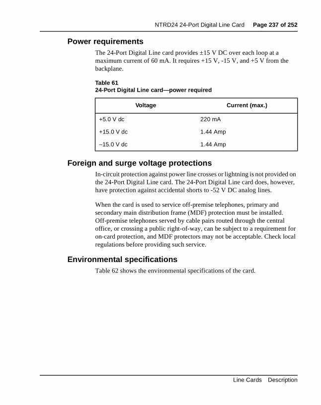
NTRD24 24-Port Digital Line Card Page 237 of 252
on er,
l for ocal
Power requirementsThe 24-Port Digital Line card provides ±15 V DC over each loop at a maximum current of 60 mA. It requires +15 V, -15 V, and +5 V from the backplane.
Foreign and surge voltage protectionsIn-circuit protection against power line crosses or lightning is not providedthe 24-Port Digital Line card. The 24-Port Digital Line card does, howevhave protection against accidental shorts to -52 V DC analog lines.
When the card is used to service off-premise telephones, primary and secondary main distribution frame (MDF) protection must be installed. Off-premise telephones served by cable pairs routed through the centraoffice, or crossing a public right-of-way, can be subject to a requirementon-card protection, and MDF protectors may not be acceptable. Check lregulations before providing such service.
Environmental specificationsTable 62 shows the environmental specifications of the card.
Table 6124-Port Digital Line card—power required
Voltage Current (max.)
+5.0 V dc 220 mA
+15.0 V dc 1.44 Amp
–15.0 V dc 1.44 Amp
Line Cards Description
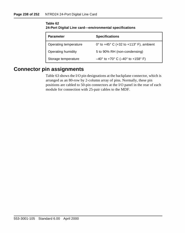
Page 238 of 252 NTRD24 24-Port Digital Line Card
ch is
ach
Connector pin assignmentsTable 63 shows the I/O pin designations at the backplane connector, whiarranged as an 80-row by 2-column array of pins. Normally, these pin positions are cabled to 50-pin connectors at the I/O panel in the rear of emodule for connection with 25-pair cables to the MDF.
Table 6224-Port Digital Line card—environmental specifications
Parameter Specifications
Operating temperature 0° to +45° C (+32 to +113° F), ambient
Operating humidity 5 to 90% RH (non-condensing)
Storage temperature –40° to +70° C (–40° to +158° F)
553-3001-105 Standard 6.00 April 2000
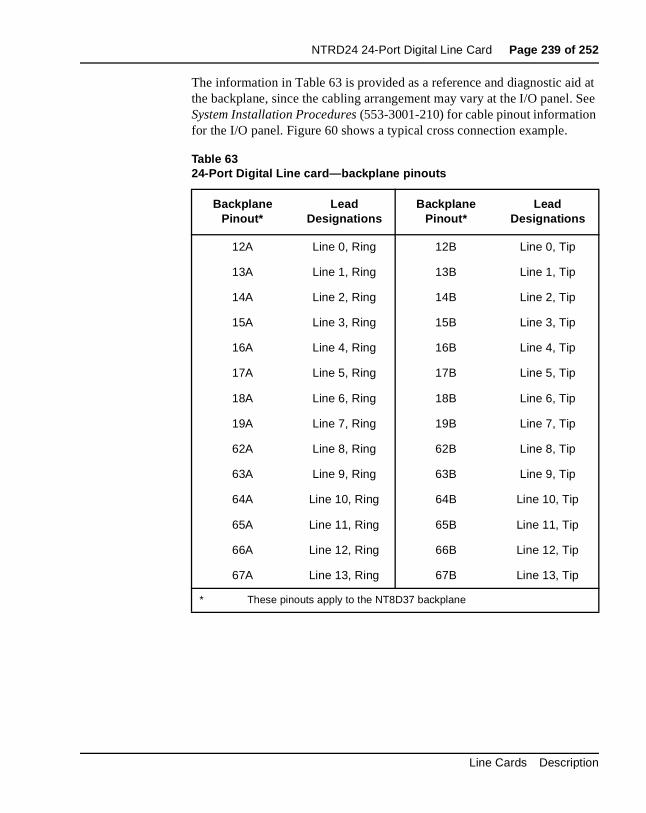
NTRD24 24-Port Digital Line Card Page 239 of 252
d at . See
The information in Table 63 is provided as a reference and diagnostic aithe backplane, since the cabling arrangement may vary at the I/O panelSystem Installation Procedures (553-3001-210) for cable pinout informationfor the I/O panel. Figure 60 shows a typical cross connection example.
Table 6324-Port Digital Line card—backplane pinouts
Backplane Pinout*
Lead Designations
Backplane Pinout*
Lead Designations
12A Line 0, Ring 12B Line 0, Tip
13A Line 1, Ring 13B Line 1, Tip
14A Line 2, Ring 14B Line 2, Tip
15A Line 3, Ring 15B Line 3, Tip
16A Line 4, Ring 16B Line 4, Tip
17A Line 5, Ring 17B Line 5, Tip
18A Line 6, Ring 18B Line 6, Tip
19A Line 7, Ring 19B Line 7, Tip
62A Line 8, Ring 62B Line 8, Tip
63A Line 9, Ring 63B Line 9, Tip
64A Line 10, Ring 64B Line 10, Tip
65A Line 11, Ring 65B Line 11, Tip
66A Line 12, Ring 66B Line 12, Tip
67A Line 13, Ring 67B Line 13, Tip
* These pinouts apply to the NT8D37 backplane
Line Cards Description
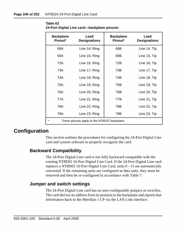
Page 240 of 252 NTRD24 24-Port Digital Line Card
ne
d lly
be
es. that
ConfigurationThis section outlines the procedures for configuring the 24-Port Digital Licard and system software to properly recognize the card.
Backward CompatibilityThe 24-Port Digital Line card is not fully backward compatible with the existing NT8D02 16-Port Digital Line Card. If the 24-Port Digital Line carreplaces a NT8D02 16-Port Digital Line Card, units 0 - 15 are automaticaconverted. If the remaining units are configured as data units, they mustremoved and then be re-configured in accordance with Table 7.
Jumper and switch settingsThe 24-Port Digital Line card has no user-configurable jumpers or switchThe card derives its address from its position in the backplane and reportsinformation back to the Meridian 1 CP via the LAN Link interface.
68A Line 14, Ring 68B Line 14, Tip
69A Line 15, Ring 69B Line 15, Tip
72A Line 16, Ring 72B Line 16, Tip
73A Line 17, Ring 73B Line 17, Tip
74A Line 18, Ring 74B Line 18, Tip
75A Line 19, Ring 75B Line 19, Tip
76A Line 20, Ring 76B Line 20, Tip
77A Line 21, Ring 77B Line 21, Tip
78A Line 22, Ring 78B Line 22, Tip
79A Line 23, Ring 79B Line 23, Tip
Table 6324-Port Digital Line card—backplane pinouts
Backplane Pinout*
Lead Designations
Backplane Pinout*
Lead Designations
* These pinouts apply to the NT8D37 backplane
553-3001-105 Standard 6.00 April 2000
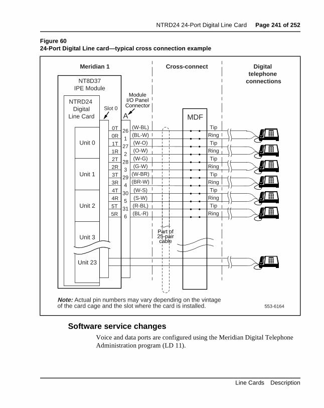
NTRD24 24-Port Digital Line Card Page 241 of 252
e
Software service changesVoice and data ports are configured using the Meridian Digital TelephonAdministration program (LD 11).
Figure 6024-Port Digital Line card—typical cross connection example
553-6164
NT8D37IPE Module
Slot 0NTRD24
DigitalLine Card
(W-BL)
(BL-W)
(W-O)
(O-W)
0T
0R
1T
1R
26
1
27
2
Meridian 1 Cross-connect Digital telephone
connections
A MDFTip
Ring
Tip
Ring
Tip
Ring
Tip
Ring
(W-G)
(G-W)
(W-BR)
(BR-W)
28
3
29
4(W-S)
(S-W)
(R-BL)
(BL-R)
4T
4R
5T
5R
2T
2R
3T
3R
30
5
31
6
Tip
Ring
Note: Actual pin numbers may vary depending on the vintage of the card cage and the slot where the card is installed.
ModuleI/O PanelConnector
Part of25-paircable
Tip
Ring
Unit 0
Unit 23
Unit 1
Unit 2
Unit 3
Line Cards Description
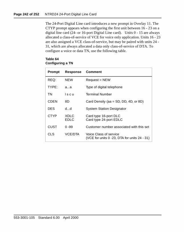
Page 242 of 252 NTRD24 24-Port Digital Line Card
e a s 23 4 -
The 24-Port Digital Line card introduces a new prompt in Overlay 11. ThCTYP prompt appears when configuring the first unit between 16 - 23 ondigital line card (24- or 16-port Digital Line card). Units 0 - 15 are alwayallocated a class-of-service of VCE for voice only application. Units 16 - are also assigned a VCE class-of-service, but may be paired with units 231, which are always allocated a data only class-of-service of DTA. To configure a voice or data TN, use the following table.
Table 64Configuring a TN
Prompt Response Comment
REQ: NEW Request = NEW
TYPE: a...a Type of digital telephone
TN l s c u Terminal Number
CDEN 8D Card Density (aa = SD, DD, 4D, or 8D)
DES d...d System Station Designator
CTYP XDLCEDLC
Card type 16-port DLCCard type 24-port EDLC
CUST 0 -99 Customer number associated with this set
CLS VCE/DTA Voice Class of service(VCE for units 0 -23, DTA for units 24 - 31)
553-3001-105 Standard 6.00 April 2000
Page 243 of 252
246
List of termsBIMP
Balance Impedance
CCITTInternational Telegraph and Telephone Consultive Committee
CIDCaller Identification
CLSClass of service
COCentral office
COSClass of service
CPCore processor
CPECustomer Premise Equipment
CSUChannel Service Unit
DTMFDual-tone multi-frequency
Line Cards Description
Page 244 of 252 List of terms
ICLInserted connection loss
IPEIntelligent peripheral equipment
LANLocal area network
LEDLight emitting diode
MDFMain Distribution Frame
MMIMan-Machine Interface
ONPOn-premise class of service
ONSOn-premises set (station)
OPSOff-premises set (station)
OPXOff-premise class of service
PBXPrivate branch exchange
PCMPulse code modulation
PSTNPublic Switched Telephone Network
553-3001-105 Standard 6.00 April 2000
List of terms Page 245 of 252
PEPeripheral equipment
PSNPublic switched network
PSTNPublic switched telephone network
RENRinger equivalence numbers
RHRelative humidity
RsyncRing synchronization
TCNTime compression multiplexed
TIMPTermination impedance
TNTerminal number
WATSWide-Area Transmission Service
Line Cards Description

Page 246 of 252 List of terms
553-3001-105 Standard 6.00 April 2000
Page 247 of 252
252
Index
,
Symbolsµ-Law companding support 23, 210
Numerics500/2500 telephones
line card for 210
AA-Law companding support 23, 210analog line call operation 27analog line cards 11
interface units 22ASCII terminals
with NT8D02 Digital Line Card 194
Bbalancing networks 23BPRZ-AMI (Bi-Polar Return to Zero-Alternate
Mark Inversion) data 25, 198, 233busses
card LAN link 20for DS-30X network loops 19IPE compared to PE 16
Ccabling
for line cards 15NT1R20 Off-Premise Station (OPS) Analog
Line Card 46, 61NT8D02 Digital Line Card 203, 238NT8D09 Analog Message Waiting Line Card
211
call signaling bits 19campus installations (off-premise applications) 11
12, 23, 41Card LAN link 20
NT1R20 Off-Premise Station (OPS) Analog Line Card 49, 52
NT8D02 Digital Line Card 197, 200, 232, 235NT8D09 Analog Message Waiting Line Card
214, 215codecs (Coder/Decoder) 22, 23, 49
NT1R20 Off-Premise Station (OPS) Analog Line Card 50
NT8D09 Analog Message Waiting Line Card 213, 214
connector pin assignmentsNT1R20 Off-Premise Station (OPS) Analog
Line Card 56, 57NT8D02 Digital Line Card 203, 204, 205, 238,
239, 241NT8D09 Analog Message Waiting Line Card
221, 222, 223
Ddata rates 19data service simultaneous with voice 13data valid bits 19digital line call operation 33digital line cards 11
interface units 25DLIC (digital line interface circuit) 25, 198
Line Cards
Page 248 of 252 Index
,
DS-30X loops 16, 17, 18, 19NT1R20 Off-Premise Station (OPS) Analog
Line Card 49, 50NT8D02 Digital Line Card 197, 198, 232, 233NT8D09 Analog Message Waiting Line Card
213, 214, 215DS-30Y network loops 20
Eelectrical specifications
NT1R20 Off-Premise Station (OPS) Analog Line Card 53
NT5D60AA CLASS Modem card 190NT8D02 Digital Line Card 201, 202, 235, 237NT8D09 Analog Message Waiting Line Card
217environmental specifications
NT1R20 Off-Premise Station (OPS) Analog Line Card 55
NT8D02 Digital Line Card 190, 203, 237NT8D09 Analog Message Waiting Line Card
220
Ggain filters 23glossary 243grounding for line protection 42
Iimpedance 23, 27
NT1R20 Off-Premise Station (OPS) Analog Line Card 50, 53, 58, 59
NT8D02 Digital Line Card 201, 236NT8D09 Analog Message Waiting Line Card
217, 218incoming (analog) calls 27IPE (intelligent peripheral equipment)
architecture 17comparison to PE modules 16DS-30X loops 18, 19installing line cards 14line cards for 11, 12
Jjumpers 15
field selectable settings symbol 48NT1R20 Off-Premise Station (OPS) Analog
Line Card 58, 60NT8D02 Digital Line Card 206, 207, 240NT8D09 Analog Message Waiting Line Card
224, 225
Kkey systems
line cards for 12, 13
LLD 10 for configuring interface units 15, 58, 224LD 11 for configuring interface units 15, 191, 206,
241LD 15 for configuring interface units 224LD 97 for configuring interface units 224line cards
for off-premise applications 11, 12, 23, 41installation 14operation 33
analog line call connection sequence 2728, 29
analog line interface units 22card LAN link 20digital line interface units 25DS-30X loops 18, 19host interface bus 16
selecting 11lines
number capacity of line cards 11loop interfaces
TCM (time compressed multiplexed) data 26,197, 198, 232, 233
loop limitsNT1R20 Off-Premise Station (OPS) Analog
Line Card 53NT8D02 Digital Line Card 201, 236NT8D09 Analog Message Waiting Line Card
217
553-3001-105 Standard 6.00 April 2000
Index Page 249 of 252
MMDF (main distribution frame)
connecting line cards 15Meridian 1 systems
related documentation 7message waiting handling
analog line calls 27, 30analog line interface units 22, 24characteristics of line cards 11, 12, 13
microcontrollers 16on NT1R20 Off-Premise Station (OPS) Analog
Line Card 49, 51on NT8D02 Digital Line Card 197, 199, 232,
234on NT8D09 Analog Message Waiting Line
Card 214, 215modems
line cards for 13with NT8D09 Analog Message Waiting Line
Card 210
NNT1R20 Off-Premise Station (OPS) Analog Line
Cardanalog line electrical characteristics 53applications 62, 63
transmission considerations 64, 66configuration
jumper straps 58, 60port-to-port loss 61, 64software service changes 58, 59
connector pin assignments 56, 57description 11, 12, 42, 45environmental specification 55faceplate 47, 48foreign and surge voltage protection 54functions
card control 51, 52card interfaces 50circuit power 52codecs 49, 50line interface units 50
power requirements 54ring limitations 55
NT5D11 Line Side T-1 Carddescription 12
NT5D11 Line Side T-1 Line Carddescription 11
NT5D60AA CLASS Modem cardconfiguration
software service changes 191electrical characteristics 190functions 186power requirements 190
Line Cards
Page 250 of 252 Index
e
NT8D02 Digital Line Cardconfiguration
jumper and switch settings 206, 207, 240software service changes 206, 241
connector pin assignments 203, 204, 205, 238, 239, 241
description 11, 13, 25, 185, 193, 227electrical characteristics 201, 202, 235, 237environmental specifications 190, 203, 237faceplate 186, 194, 195, 228foreign and surge voltage protection 202, 237functions 196, 197, 231, 232
card control 199, 234card interfaces 198, 233Card LAN interface 197, 200, 232, 235digital line interfaces 197, 198, 232, 233microcontroller 197, 199, 232, 234sanity timer 200, 235TCM loop interface circuit 198, 233
loop limits 201, 236power requirements 202, 237sanity timer 197, 199, 232, 234
NT8D09 Analog Message Waiting Line Cardconfiguration
jumper and switch settings 224, 225software service changes 224
connector pin assignments 221, 222, 223description 11, 13, 209, 211electrical specifications 217environmental specifications 220faceplate 211, 212foreign and surge voltage protection 220frequency response 218functions
card control 215card interfaces 213circuit power 215codecs 213, 214line interface units 213, 214microcontroller 214, 215
loop limits 217message channel noise 218overload level 218port-to-port loss 224power requirements 219
Ooff hook detection
analog line interface units 22off-hook detection
analog line interface units 24analog lines 27
off-premise applicationscompared to off-premise extension (OPX)
service 62line cards for 11, 12, 23, 41
off-premise extension (OPX) servicecompared to off-premise station (OPS) servic
62outgoing (analog) calls 27
PPCM (pulse code modulated) voice data 19
553-3001-105 Standard 6.00 April 2000
Index Page 251 of 252
PE (peripheral equipment)comparison to IPE modules 16installing line cards 14line cards for 11
port-to-port lossNT1R20 Off-Premise Station (OPS) Analog
Line Card 61, 64NT8D09 Analog Message Waiting Line Card
224power requirements
NT1R20 Off-Premise Station (OPS) Analog Line Card 49, 52, 54
NT5D60AA CLASS Modem card 190NT8D02 Digital Line Card 202, 237NT8D09 Analog Message Waiting Line Card
219
QQPC192 Off-Premise Extension (OPX) Analog
Line Carddescription 11
Rrelated documentation 7ringer limitations
NT1R20 Off-Premise Station (OPS) Analog Line Card 55
Ssignaling words 20SLIC (subscriber line interface circuit) 23switches 15
TTCM (time compressed multiplexed) data 19, 25
loop interfaces 26, 197, 198, 232, 233terminal equipment
connecting line cards 15testing
self-tests by IPE line cards 21self-tests by NT1R20 OPS card 47
timeslots 19tip and ring facilities 13, 18, 27
Vvariable gain filters 23voice-only communication 13voltage surge protection 12, 23, 42
grounding 42NT1R20 Off-Premise Station (OPS) Analog
Line Card 54NT8D02 Digital Line Card 202, 237NT8D09 Analog Message Waiting Line Card
220
Line Cards

Page 252 of 252 Index
553-3001-105 Standard 6.00 April 2000

Family Product Manual Contacts Copyright FCC notice Trademarks Document number Product release Document release Date Publish
Meridian 1
Line CardsDescription
Copyright © 1994–2000 Nortel NetworksAll Rights ReservedInformation is subject to change without notice. Nortel Networks reserves the right to make changes in design or components as progress in engineering and manufacturing may warrant. This equipment has been tested and found to comply with the limits for a Class A digital device pursuant to Part 15 of the FCC rules, and the radio interference regulations of Industry Canada. These limits are designed to provide reasonable protection against harmful interference when the equipment is operated in a commercial environment. This equipment generates, uses and can radiate radio frequency energy, and if not installed and used in accordance with the instruction manual, may cause harmful interference to radio communications. Operation of this equipment in a residential area is likely to cause harmful interference in which case the user will be required to correct the interference at their own expense.SL-1 and Meridian 1 are trademarks of Nortel Networks.Publication number: 553-3001-105Document release: Standard 6.00Date: April 2000Printed in Canada


![2019 Christmas Cards - EASE Products...三] I 2019 Christmas Cards Greeting, Mini Cards & Post Cards CONTENTS GREETING CARDS 03 Basic Christmas Cards 05 Import & Turnowsky Christmas](https://img.pdfslide.net/doc/110x75/5f07a85f7e708231d41e157a/2019-christmas-cards-ease-products-i-2019-christmas-cards-greeting-mini.jpg)