Embed Size (px)
Citation preview
Merminga, LRP2007, Jan 12-14 2007
e + p/A FacilitiesLia Merminga
Center for Advanced Studies of Accelerators
Jefferson Laboratory
January 12-14, 2007
APS Division of Nuclear Physics: 2007 Long Range Plan
Joint Town Meetings on Quantum Chromodynamics
Merminga, LRP2007, Jan 12-14 2007
OutlineOutline EIC Design Specifications
Proposed EIC Designs
Luminosity Concepts
Machine Designs
• eRHIC
• ELIC
• LHeC
R&D Required
Performance Summary
Conclusions
Merminga, LRP2007, Jan 12-14 2007
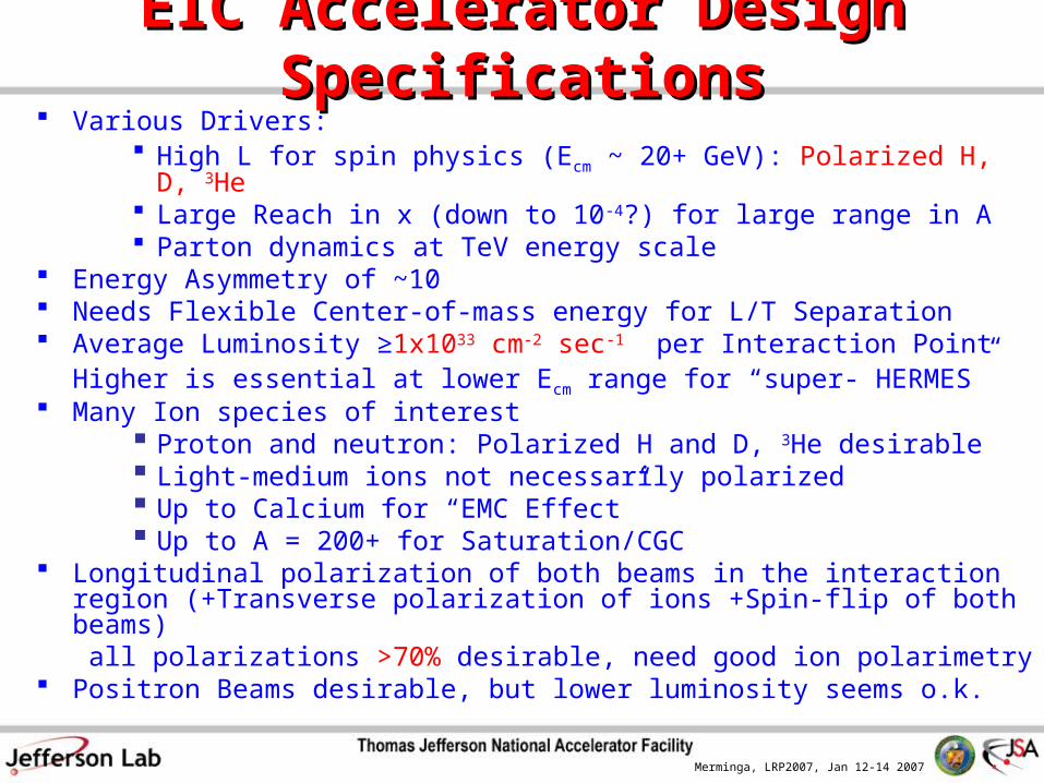
EIC Accelerator Design SpecificationsEIC Accelerator Design Specifications Various Drivers:
High L for spin physics (Ecm ~ 20+ GeV): Polarized H, D, 3He Large Reach in x (down to 10-4?) for large range in A Parton dynamics at TeV energy scale
Energy Asymmetry of ~10 Needs Flexible Center-of-mass energy for L/T Separation Average Luminosity ≥1x1033 cm-2 sec-1 per Interaction Point
Higher is essential at lower Ecm range for “super- HERMES” Many Ion species of interest
Proton and neutron: Polarized H and D, 3He desirable Light-medium ions not necessarily polarized Up to Calcium for “EMC Effect” Up to A = 200+ for Saturation/CGC
Longitudinal polarization of both beams in the interaction region (+Transverse polarization of ions +Spin-flip of both beams)
all polarizations >70% desirable, need good ion polarimetry Positron Beams desirable, but lower luminosity seems o.k.
Merminga, LRP2007, Jan 12-14 2007
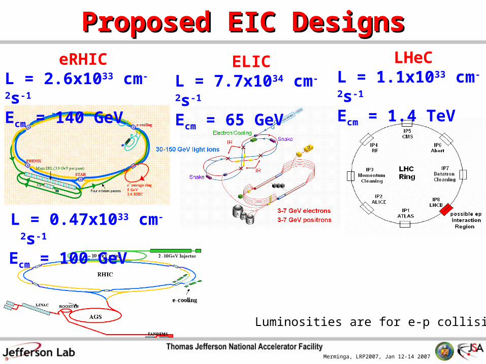
Proposed EIC DesignsProposed EIC DesignseRHIC
L = 2.6x1033 cm-2s-1 Ecm = 140 GeV
Luminosities are for e-p collisions
LHeCL = 1.1x1033 cm-2s-1 Ecm = 1.4 TeV
ELICL = 7.7x1034 cm-2s-1 Ecm = 65 GeV
L = 0.47x1033 cm-2s-1
Ecm = 100 GeV
Merminga, LRP2007, Jan 12-14 2007
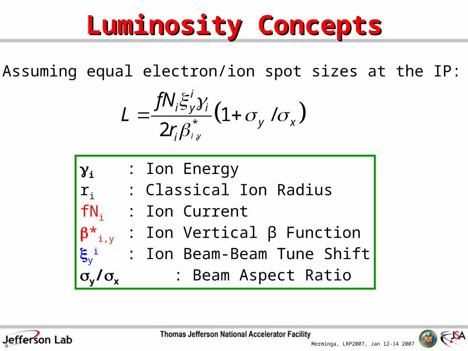
Luminosity ConceptsLuminosity Concepts
,
*1 /
2 i y
ii y i
y xi
fNL
r
i : Ion Energyri : Classical Ion RadiusfNi : Ion Current*i,y : Ion Vertical β Functiony
i : Ion Beam-Beam Tune Shifty/x : Beam Aspect Ratio
Assuming equal electron/ion spot sizes at the IP:
Merminga, LRP2007, Jan 12-14 2007
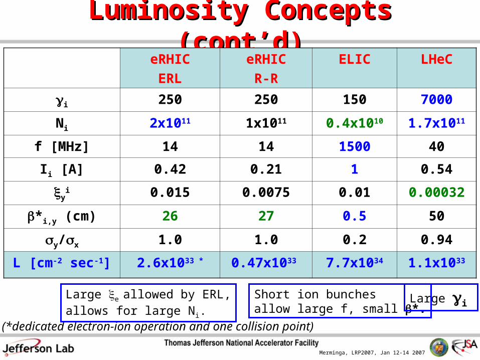
Luminosity Concepts (cont’d)Luminosity Concepts (cont’d)eRHIC
ERL
eRHIC
R-R
ELIC LHeC
i 250 250 150 7000
Ni 2x10¹¹ 1x10¹¹ 0.4x10¹⁰ 1.7x10¹¹
f [MHz] 14 14 1500 40
Ii [A] 0.42 0.21 1 0.54
yi 0.015 0.0075 0.01 0.00032
*i,y (cm) 26 27 0.5 50
y/x 1.0 1.0 0.2 0.94
L [cm-2 sec-1] 2.6x1033 * 0.47x1033 7.7x1034 1.1x1033
(*dedicated electron-ion operation and one collision point)
Large e allowed by ERL,allows for large Ni.
Short ion bunches allow large f, small *.
Large i
Merminga, LRP2007, Jan 12-14 2007
Machine DesignsMachine Designs
Merminga, LRP2007, Jan 12-14 2007
eRHIC• Integrated electron-nucleon luminosity of ~ 50 fb-1 over about a decade for both highly
polarized nucleon and nuclear (A = 2-208) RHIC beams.
50-250 GeV polarized protons up to 100 GeV/n gold ions up to 167 GeV/n polarized 3He ions
• Two accelerator design options developed in parallel (2004 Zeroth-Order Design Report):
ERL-based design (“Linac-Ring”; presently most promising design):• Superconducting energy recovery linac (ERL) for the polarized electron beam.• Peak luminosity of 2.6 1033 cm-2s-1 with potential for even higher luminosities.• R&D for a high-current polarized electron source needed to achieve the design
goals. Ring-Ring option:
• Electron storage ring for polarized electron or positron beam. • Technologically more mature with peak luminosity of 0.47 1033 cm-2s-1.
• Decision on polarized leptons approach will be driven by a number of considerations, among them experimental requirements, cost and timeline.
Merminga, LRP2007, Jan 12-14 2007
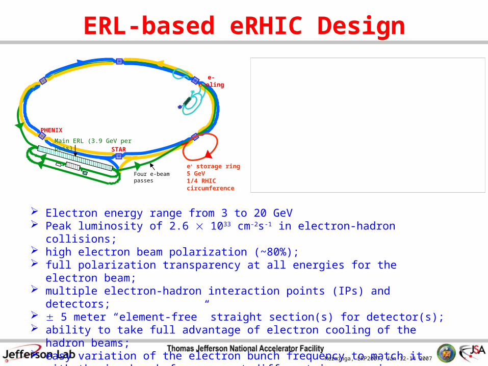
ERL-based eRHIC Design
PHENIX
STAR
e-cooling
Four e-beam passes
e+ storage ring5 GeV1/4 RHIC circumference
Main ERL (3.9 GeV per pass)
Electron energy range from 3 to 20 GeV Peak luminosity of 2.6 1033 cm-2s-1 in electron-hadron collisions; high electron beam polarization (~80%); full polarization transparency at all energies for the electron beam; multiple electron-hadron interaction points (IPs) and detectors; 5 meter “element-free” straight section(s) for detector(s); ability to take full advantage of electron cooling of the hadron beams; easy variation of the electron bunch frequency to match it with the ion bunch frequency at
different ion energies.
0
0.5
1
1.5
2
2.5
3
20 30 40 50 60 70 80 90 100 110 120 130 140 150
Center-Of-Mass Energy, GeV
Pe
ak
Lu
min
os
ity
, 1
033 c
m-2
s-1
3GeV(e)-50GeV(p) 20GeV(e)-50GeV(p)
3GeV(e)-250GeV(p) 20GeV(e)-250GeV(p)
0
0.5
1
1.5
2
2.5
3
20 30 40 50 60 70 80 90 100 110 120 130 140 150
Center-Of-Mass Energy, GeV
Pe
ak
Lu
min
os
ity
, 1
033 c
m-2
s-1
3GeV(e)-50GeV(p) 20GeV(e)-50GeV(p)
3GeV(e)-250GeV(p) 20GeV(e)-250GeV(p)
Merminga, LRP2007, Jan 12-14 2007
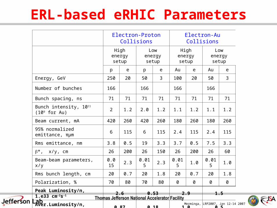
ERL-based eRHIC ParametersElectron-Proton Collisions Electron-Au Collisions
High energy setup
Low energy setup
High energy setup
Low energy setup
p e p e Au e Au e
Energy, GeV 250 20 50 3 100 20 50 3
Number of bunches 166 166 166 166
Bunch spacing, ns 71 71 71 71 71 71 71 71
Bunch intensity, 1011 (109 for Au) 2 1.2 2.0 1.2 1.1 1.2 1.1 1.2
Beam current, mA 420 260 420 260 180 260 180 260
95% normalized emittance, πμm 6 115 6 115 2.4 115 2.4 115
Rms emittance, nm 3.8 0.5 19 3.3 3.7 0.5 7.5 3.3
*, x/y, cm 26 200 26 150 26 200 26 60
Beam-beam parameters, x/y 0.015 2.3 0.015 2.3 0.015 1.0 0.015 1.0
Rms bunch length, cm 20 0.7 20 1.8 20 0.7 20 1.8
Polarization, % 70 80 70 80 0 0 0 0
Peak Luminosity/n, 1.e33 cm-2s-1 2.6 0.53 2.9 1.5
Aver.Luminosity/n, 1.e33 cm-2s-1 0.87 0.18 1.0 0.5
Luminosity integral /week, pb-1 530 105 580 290
Merminga, LRP2007, Jan 12-14 2007
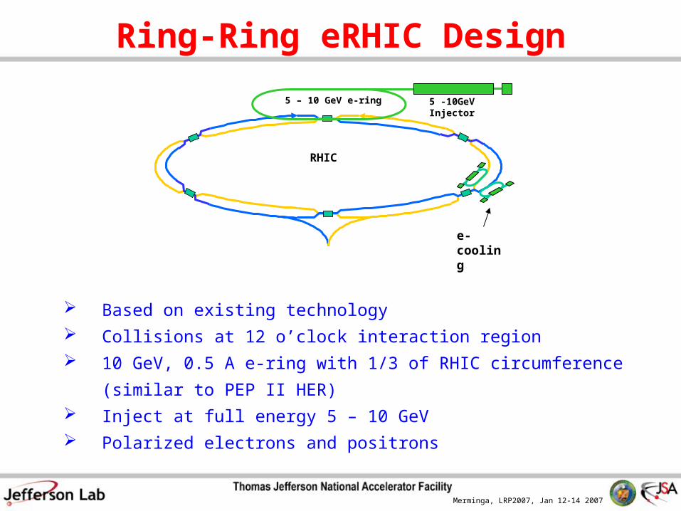
Ring-Ring eRHIC Design
Based on existing technology
Collisions at 12 o’clock interaction region
10 GeV, 0.5 A e-ring with 1/3 of RHIC circumference (similar to PEP II HER)
Inject at full energy 5 – 10 GeV
Polarized electrons and positrons
RHIC
5 – 10 GeV e-ring
e-cooling
5 -10GeV Injector
Merminga, LRP2007, Jan 12-14 2007
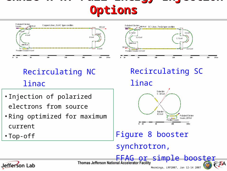
0 50 10010 150 200 250 275 m
2 GeV4 GeV
6 GeV4 GeV
200 MeV
200 MeV
Polarized ElectronSource
Positron Source
2 GeV
Copper Linac, SLAC type cavities10 GeV
8 GeV
1.7 GeV3.3 GeV
5 GeV6.7 GeV
200 MeV
200 MeV
Polarized ElectronSource
Positron Source 3.3 GeV
SC Linac, Tesla type cavities
8.3 GeV10 GeV
0 50 10010 150 200 250 275 m
Recirculating NC linac Recirculating SC linac
Figure 8 booster synchrotron,
FFAG or simple booster
Injection0.5 GeV
Polarized ElectronSource, 20 MeV
Positron Source
0 50 10010 150 m
Extraction5 - 10 GeV
• Injection of polarized electrons from
source
• Ring optimized for maximum current
• Top-off
eRHIC R-R: Full Energy Injection OptionseRHIC R-R: Full Energy Injection Options
Merminga, LRP2007, Jan 12-14 2007
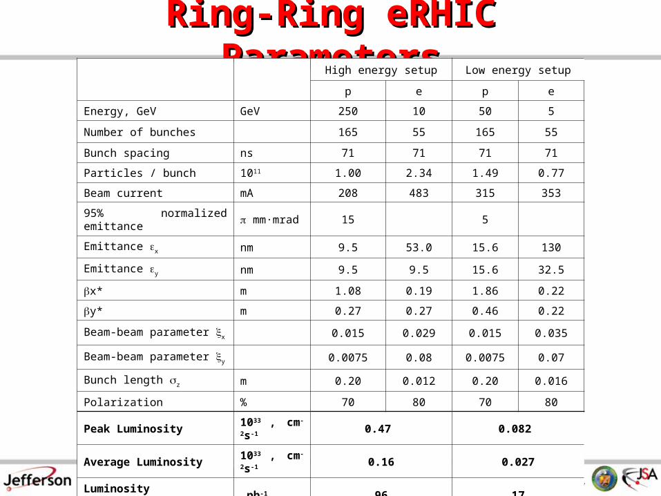
Ring-Ring eRHIC ParametersRing-Ring eRHIC ParametersHigh energy setup Low energy setup
p e p e
Energy, GeV GeV 250 10 50 5
Number of bunches 165 55 165 55
Bunch spacing ns 71 71 71 71
Particles / bunch 1011 1.00 2.34 1.49 0.77
Beam current mA 208 483 315 353
95% normalized emittance mm·mrad 15 5
Emittance x nm 9.5 53.0 15.6 130
Emittance y nm 9.5 9.5 15.6 32.5
x* m 1.08 0.19 1.86 0.22
y* m 0.27 0.27 0.46 0.22
Beam-beam parameter x 0.015 0.029 0.015 0.035
Beam-beam parameter y 0.0075 0.08 0.0075 0.07
Bunch length z m 0.20 0.012 0.20 0.016
Polarization % 70 80 70 80
Peak Luminosity 1033 , cm-2s-1 0.47 0.082
Average Luminosity 1033 , cm-2s-1 0.16 0.027
Luminosity Integral /week pb-1 96 17
Merminga, LRP2007, Jan 12-14 2007
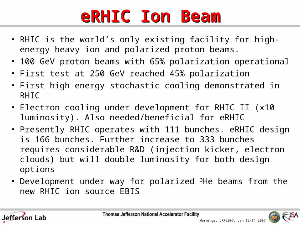
eRHIC Ion BeameRHIC Ion Beam• RHIC is the world’s only existing facility for high-energy
heavy ion and polarized proton beams.• 100 GeV proton beams with 65% polarization operational • First test at 250 GeV reached 45% polarization• First high energy stochastic cooling demonstrated in RHIC• Electron cooling under development for RHIC II (x10
luminosity). Also needed/beneficial for eRHIC• Presently RHIC operates with 111 bunches. eRHIC design is
166 bunches. Further increase to 333 bunches requires considerable R&D (injection kicker, electron clouds) but will double luminosity for both design options
• Development under way for polarized 3He beams from the new RHIC ion source EBIS
Merminga, LRP2007, Jan 12-14 2007
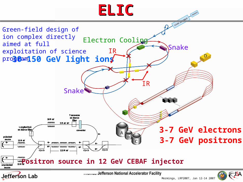
Electron Cooling
Snake
Snake
3-7 GeV electrons
30-150 GeV light ions
IR
IR
3-7 GeV positrons115 MeV
converter
e-
e-15 MeV
5 MeV e+
e-
e-
e-
e+
10 MeV
15 MeV
e-
e+e+
unpolarizedsource
polarized source
During positron production: - polarized source is off - dipoles are turned on
dipole
Transverse emittance
filter
Longitudinal emittance filter
dipole dipole115 MeV
converter
e-
e-15 MeV
5 MeV e+
e-
e-
e-
e+
10 MeV
15 MeV
e-
e+e+
unpolarizedsource
polarized source
During positron production: - polarized source is off - dipoles are turned on
dipole
Transverse emittance
filter
Longitudinal emittance filter
dipole dipole
ELICELIC
Positron source in 12 GeV CEBAF injector
Green-field design of ion complex directly aimed at full exploitation of science program.
Merminga, LRP2007, Jan 12-14 2007
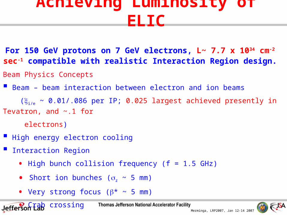
Achieving Luminosity of ELIC
For 150 GeV protons on 7 GeV electrons, L~ 7.7 x 1034 cm-2 sec-1 compatible with realistic Interaction Region design.
Beam Physics Concepts
Beam – beam interaction between electron and ion beams
(i/e ~ 0.01/.086 per IP; 0.025 largest achieved presently in Tevatron, and ~.1 for
electrons)
High energy electron cooling
Interaction Region
• High bunch collision frequency (f = 1.5 GHz)
• Short ion bunches (z ~ 5 mm)
• Very strong focus (* ~ 5 mm)
• Crab crossing

Merminga, LRP2007, Jan 12-14 2007
Short bunches make Crab Crossing feasible.
SRF deflectors at 1.5 GHz can be used to create a proper bunch tilt.
SRF dipole
Final lens FF
Crab CrossingCrab Crossing
Parasitic collisions are avoided without loss of luminosity.
Merminga, LRP2007, Jan 12-14 2007
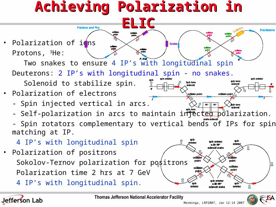
Achieving Polarization in ELICAchieving Polarization in ELIC
• Polarization of ions
Protons, 3He:
Two snakes to ensure 4 IP’s with longitudinal spin
Deuterons: 2 IP’s with longitudinal spin - no snakes.
Solenoid to stabilize spin. • Polarization of electrons
- Spin injected vertical in arcs.
- Self-polarization in arcs to maintain injected polarization.
- Spin rotators complementary to vertical bends of IPs for spin matching at IP.
4 IP’s with longitudinal spin• Polarization of positrons
Sokolov-Ternov polarization for positrons
Polarization time 2 hrs at 7 GeV
4 IP’s with longitudinal spin.
snake solenoid
spin rotator spin rotator
collision point collision point
Spin tune solenoid
spin tune solenoid
spin tune solenoid
spin tune solenoid
ii
e
e
spin
90º 90º
snake solenoid
spin rotator spin rotator
collision point collision point
Spin tune solenoid
spin tune solenoid
spin tune solenoid
spin tune solenoid
ii
e
e
spin
90º 90º
collision point
collision point
collision point
collision point
Solenoid
d
Deuteronscollision
point
collision point
collision point
collision point
Solenoid
d
collision point
collision point
collision point
collision point
Solenoid
d
collision point
collision point
collision point
collision point
Solenoid
d
Deuteronscollision
point
collision point
collision point
collision point
Snake
P, He3
Protons and 3He
collision point
collision point
collision point
collision point
Snake
P, He3
collision point
collision point
collision point
collision point
Snake
P, He3
collision point
collision point
collision point
collision point
Snake
P, He3
Protons and 3He
spin rotator
spin rotator
spin rotator
spin rotator
collision point
spin rotator with 90º
solenoid snake
collision point
collision point
collision point
spin rotator with 90º
solenoid snake
spin rotator
spin rotator
spin rotator
spin rotator
collision point
spin rotator with 90º
solenoid snake
collision point
collision point
collision point
spin rotator with 90º
solenoid snake
Merminga, LRP2007, Jan 12-14 2007
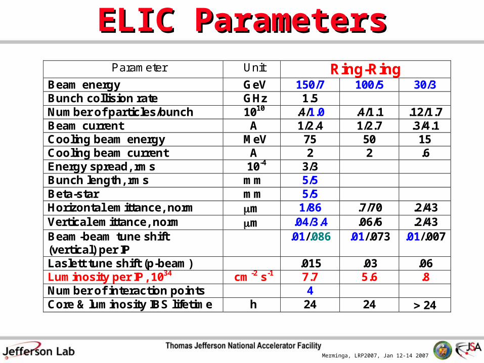
ELIC ParametersELIC Parameters Parameter Unit Ring-Ring Beam energy GeV 150/7 100/5 30/3 Bunch collision rate GHz 1.5 Number of particles/bunch 1010 .4/1.0 .4/1.1 .12/1.7 Beam current A 1/2.4 1/2.7 .3/4.1 Cooling beam energy MeV 75 50 15 Cooling beam current A 2 2 .6 Energy spread, rms 10-4 3/3 Bunch length, rms mm 5/5 Beta-star mm 5/5 Horizontal emittance, norm m 1/86 .7/70 .2/43 Vertical emittance, norm m .04/3.4 .06/6 .2/43 Beam-beam tune shift (vertical) per IP
.01/.086 .01/.073 .01/.007
Laslett tune shift (p-beam) .015 .03 .06 Luminosity per IP, 1034 cm-2 s-1 7.7 5.6 .8 Number of interaction points 4 Core & luminosity IBS lifetime h 24 24 24
Merminga, LRP2007, Jan 12-14 2007
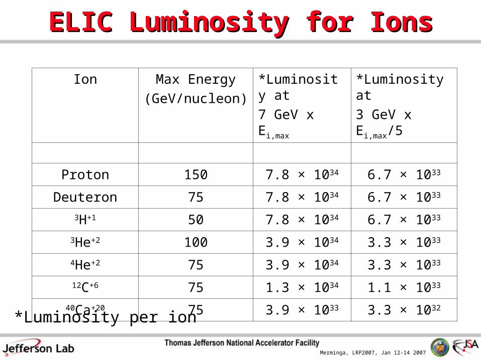
ELIC Luminosity for IonsELIC Luminosity for Ions
Ion Max Energy
(GeV/nucleon)
*Luminosity at
7 GeV x Ei,max
*Luminosity at
3 GeV x Ei,max/5
Proton 150 7.8 × 1034 6.7 × 1033
Deuteron 75 7.8 × 1034 6.7 × 1033
3H+1 50 7.8 × 1034 6.7 × 1033
3He+2 100 3.9 × 1034 3.3 × 1033
4He+2 75 3.9 × 1034 3.3 × 1033
12C+6 75 1.3 × 1034 1.1 × 1033
40Ca+20 75 3.9 × 1033 3.3 × 1032
*Luminosity per ion
Merminga, LRP2007, Jan 12-14 2007
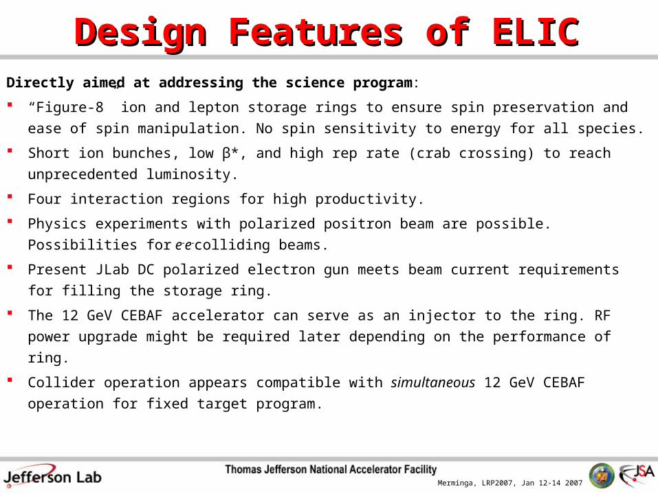
Design Features of ELICDesign Features of ELICDirectly aimed at addressing the science program:
“Figure-8” ion and lepton storage rings to ensure spin preservation and ease of spin
manipulation. No spin sensitivity to energy for all species.
Short ion bunches, low β*, and high rep rate (crab crossing) to reach unprecedented
luminosity.
Four interaction regions for high productivity.
Physics experiments with polarized positron beam are possible. Possibilities for e-e-
colliding beams.
Present JLab DC polarized electron gun meets beam current requirements for filling
the storage ring.
The 12 GeV CEBAF accelerator can serve as an injector to the ring. RF power
upgrade might be required later depending on the performance of ring.
Collider operation appears compatible with simultaneous 12 GeV CEBAF operation
for fixed target program.
Merminga, LRP2007, Jan 12-14 2007
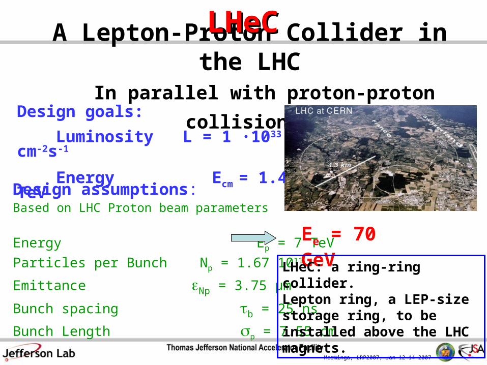
A Lepton-Proton Collider in the LHC In parallel with proton-proton collisions
LHeCLHeC
Design goals:
Luminosity L = 1 ∙1033 cm-2s-1
Energy Ecm = 1.4 TeV
Design assumptions: Based on LHC Proton beam parameters
Energy Ep = 7 TeV
Particles per Bunch Np = 1.67 1011
Emittance Np = 3.75 µm
Bunch spacing b = 25 ns
Bunch Length p = 7.55 cm
Ee = 70 GeV
LHeC: a ring-ring collider. Lepton ring, a LEP-size storage ring, to be installed above the LHC magnets.
Merminga, LRP2007, Jan 12-14 2007
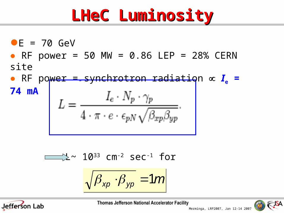
LHeC LuminosityLHeC Luminosity
L~ 1033 cm-2 sec-1 for
●E = 70 GeV ● RF power = 50 MW = 0.86 LEP = 28% CERN site● RF power = synchrotron radiation Ie = 74 mA
mypxp 1 mypxp 1
Merminga, LRP2007, Jan 12-14 2007
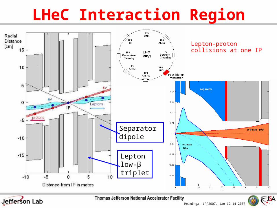
LHeC Interaction Region
Lepton-proton collisions at one IP
Lepton low-β triplet
Separator dipole
Merminga, LRP2007, Jan 12-14 2007
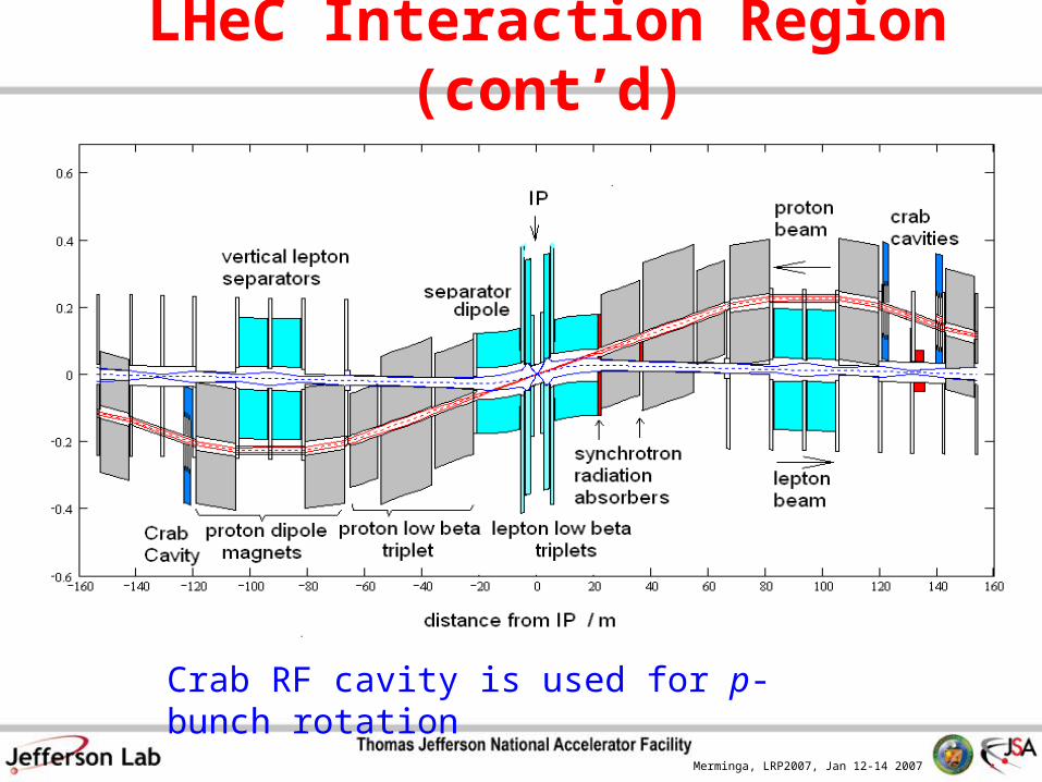
LHeC Interaction Region (cont’d)
Crab RF cavity is used for p-bunch rotation
Merminga, LRP2007, Jan 12-14 2007
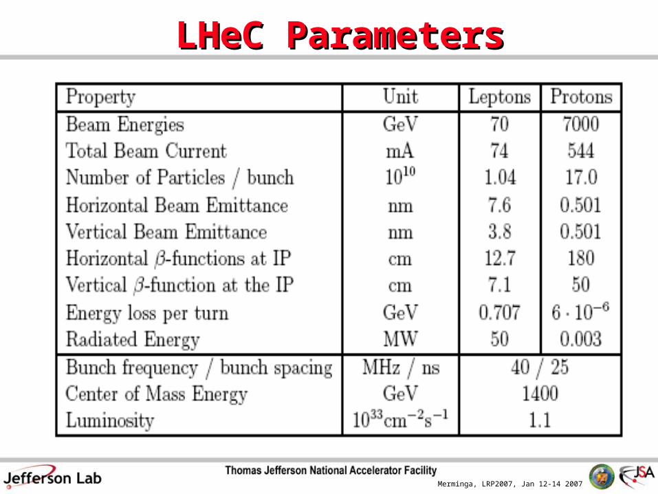
LHeC ParametersLHeC Parameters
Merminga, LRP2007, Jan 12-14 2007
R&D Required R&D Required
for for
eRHIC and ELIC eRHIC and ELIC
Merminga, LRP2007, Jan 12-14 2007
Common R&D TopicsCommon R&D Topics
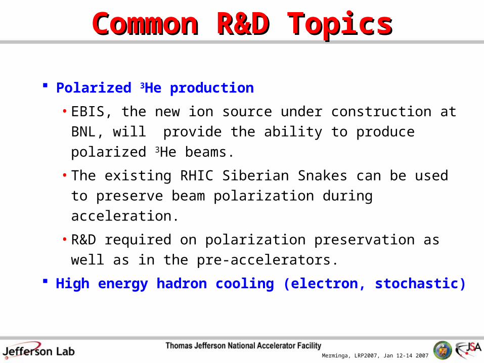
Polarized 3He production
• EBIS, the new ion source under construction at BNL,
will provide the ability to produce polarized 3He
beams.
• The existing RHIC Siberian Snakes can be used to
preserve beam polarization during acceleration.
• R&D required on polarization preservation as well as in
the pre-accelerators.
High energy hadron cooling (electron, stochastic)
Merminga, LRP2007, Jan 12-14 2007
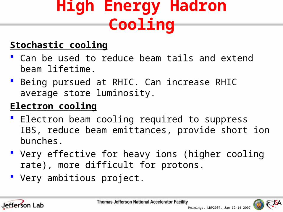
High Energy Hadron Cooling
Stochastic cooling Can be used to reduce beam tails and extend beam lifetime.
Being pursued at RHIC. Can increase RHIC average store
luminosity.
Electron cooling Electron beam cooling required to suppress IBS, reduce
beam emittances, provide short ion bunches. Very effective for heavy ions (higher cooling rate), more
difficult for protons. Very ambitious project.
Merminga, LRP2007, Jan 12-14 2007
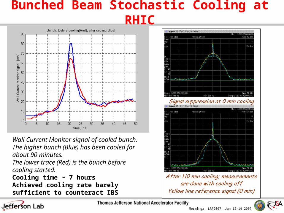
Bunched Beam Stochastic Cooling at RHIC
Wall Current Monitor signal of cooled bunch. The higher bunch (Blue) has been cooled for about 90 minutes. The lower trace (Red) is the bunch before cooling started.Cooling time ~ 7 hoursAchieved cooling rate barely sufficient to counteract IBS

Merminga, LRP2007, Jan 12-14 2007
Relativistic Electron Cooling at FNALRelativistic Electron Cooling at FNAL Fermilab made the next step in electron cooling technology Main Parameters
4.34 MeV electron beam [x20 previous experience], 0.5 A DC Magnetic field in the cooling section - 100 G
Feasibility of electron cooling with bunched beams remains to be demonstrated.
Merminga, LRP2007, Jan 12-14 2007
from RHIC
30 MeV
54.5 MeV
4.7 MeVLaser
54.5 MeV
1
2 3
44’
5
7
8
to RHIC
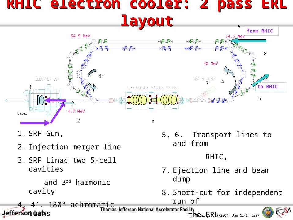
RHIC electron cooler: 2 pass ERL layoutRHIC electron cooler: 2 pass ERL layout
1. SRF Gun,
2. Injection merger line
3. SRF Linac two 5-cell cavities
and 3rd harmonic cavity
4, 4’. 180° achromatic turns
6
5, 6. Transport lines to and from
RHIC,
7. Ejection line and beam dump
8. Short-cut for independent run of
the ERL.

Merminga, LRP2007, Jan 12-14 2007
R&D Required for eRHICR&D Required for eRHIC R&D Required for Ion Beam – Applies to ERL and Ring-Ring eRHIC
• Increase number of bunches in RHIC From 111 to 166 within reach – 333 require significant R&D
R&D Required for Electron Beam - For ERL-eRHIC only• High Current Polarized Electron Source
Required average current 260 mA, 20 nC/bunchPresent state of art in polarized photocathode source:
0.3 mA average current (CEBAF, ~1 mA is expected to be reached shortly), 10 nC/bunch (SLC), 50mA/cm2 (CEBAF)
CEBAF, ILC, EIC developments expected to accelerate progress.
• Energy Recovery LinacsRequired 10X260 mA at ~20nC/bunchPresent state of art in SRF ERL: 2x10 mA at the JLab FEL at 135 pC/bunchNew BNL and JLab SRF cavity designs provide Amp level stability.
Linac ring beam-beam limits
Merminga, LRP2007, Jan 12-14 2007
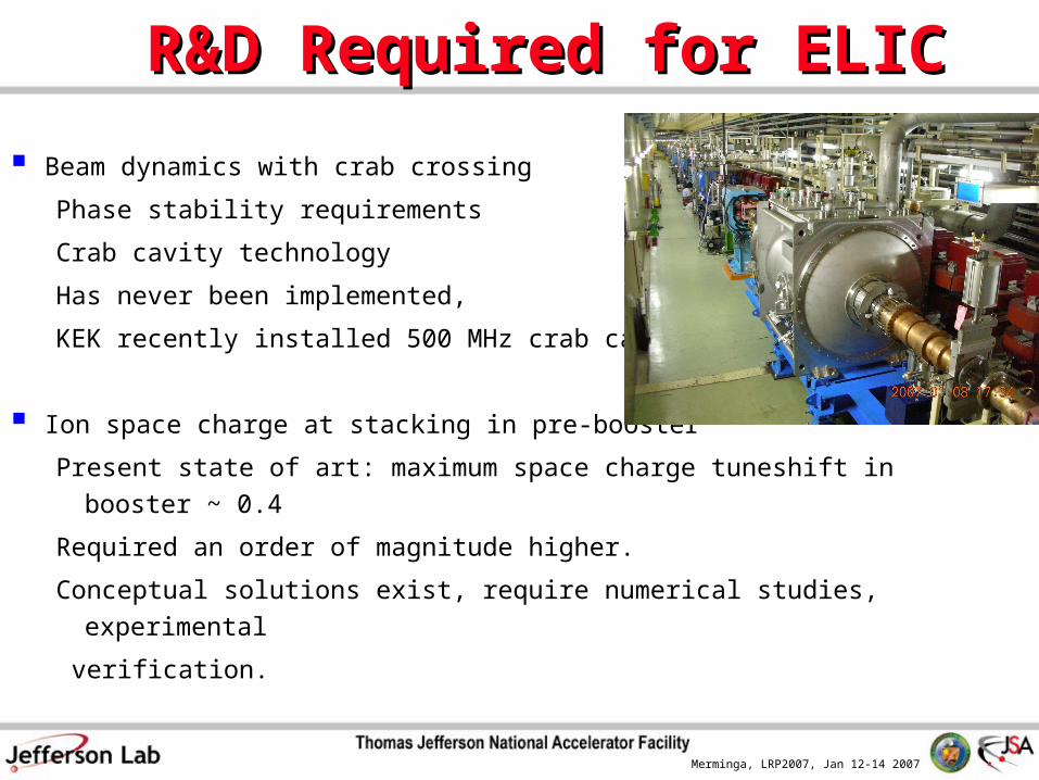
R&D Required for ELICR&D Required for ELIC
Beam dynamics with crab crossing
Phase stability requirements
Crab cavity technology
Has never been implemented,
KEK recently installed 500 MHz crab cavity
Ion space charge at stacking in pre-booster
Present state of art: maximum space charge tuneshift in booster ~ 0.4
Required an order of magnitude higher.
Conceptual solutions exist, require numerical studies, experimental
verification.
Merminga, LRP2007, Jan 12-14 2007
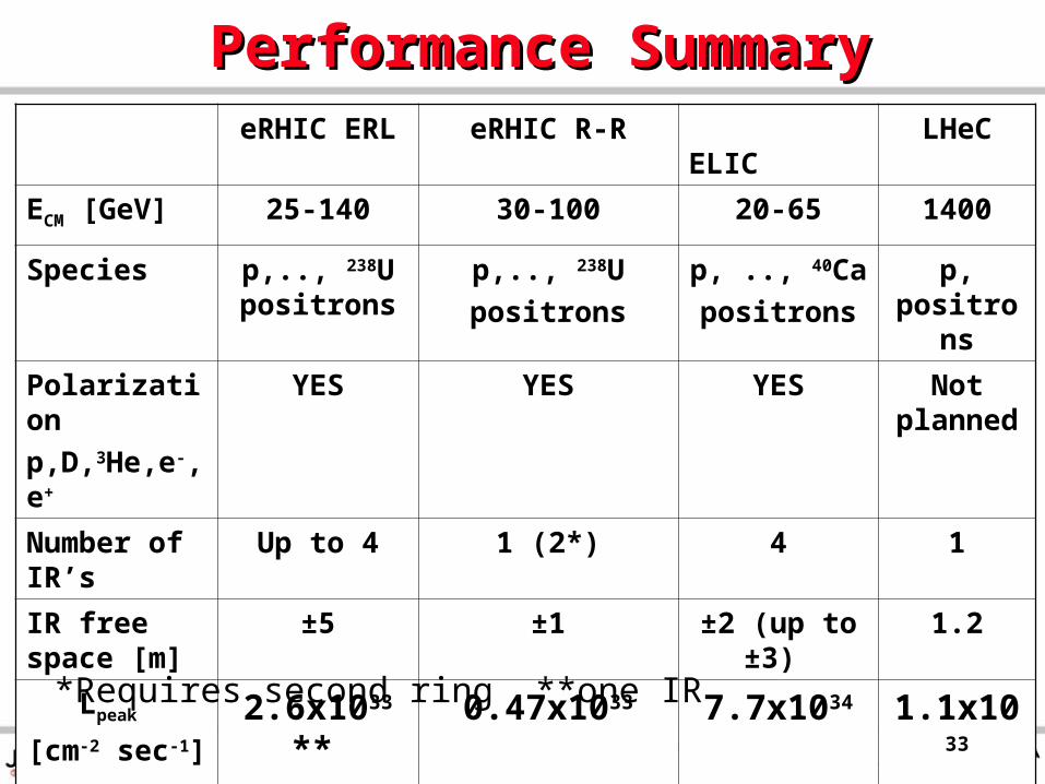
Performance SummaryPerformance SummaryeRHIC ERL eRHIC R-R ELIC LHeC
ECM [GeV] 25-140 30-100 20-65 1400
Species p,.., 238U positrons
p,.., 238U
positrons
p, .., 40Ca
positrons
p, positrons
Polarization
p,D,3He,e-,e+
YES YES YES Not planned
Number of IR’s
Up to 4 1 (2*) 4 1
IR free space [m]
±5 ±1 ±2 (up to ±3) 1.2
Lpeak
[cm-2 sec-1]
2.6x1033 ** 0.47x1033 7.7x1034 1.1x1033
*Requires second ring **one IR
Merminga, LRP2007, Jan 12-14 2007
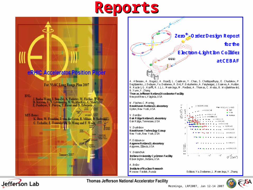
ReportsReports
Zeroth–Order Design Report
for the
Electron-Light Ion Collider
at CEBAF
A. Afanasev, A. Bogacz, A. Bruell, L. Cardman, Y. Chao, S. Chattopadhyay, E. Chudakov, P. Degtiarenko, J. Delayen, Ya. Derbenev, R. Ent, P. Evtushenko, A. Freyberger, J. Grames, A. Hutton, R. Kazimi, G. Krafft, R. Li, L. Merminga, M. Poelker, A. Thomas, C. Weiss, B. Wojtsekhowski, B. Yunn, Y. Zhang Thomas Jefferson National Accelerator Facility Newport News, Virginia, USA W. Fischer, C. Montag Brookhaven National Laboratory Upton, New York, USA V. Danilov Oak Ridge National Laboratory Oak Ridge, Tennessee, USA V. Dudnikov Brookhaven Technology Group New York, New York, USA P. Ostroumov Argonne National Laboratory Argonne, Illinois, USA
V. Derenchuk
Indiana University Cyclotron Facility Bloomington, Indiana, USA
A. Belov
Institute of Nuclear Research Moscow-Troitsk, Russia Editors: Ya. Derbenev, L. Merminga, Y. Zhang
Merminga, LRP2007, Jan 12-14 2007
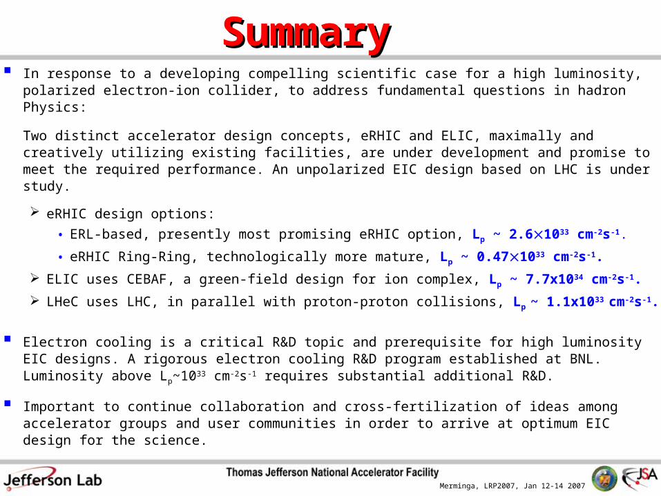
SummarySummary In response to a developing compelling scientific case for a high luminosity, polarized
electron-ion collider, to address fundamental questions in hadron Physics:
Two distinct accelerator design concepts, eRHIC and ELIC, maximally and creatively utilizing existing facilities, are under development and promise to meet the required performance. An unpolarized EIC design based on LHC is under study.
eRHIC design options:
• ERL-based, presently most promising eRHIC option, Lp ~ 2.61033 cm-2s-1.
• eRHIC Ring-Ring, technologically more mature, Lp ~ 0.471033 cm-2s-1.
ELIC uses CEBAF, a green-field design for ion complex, Lp ~ 7.7x1034 cm-2s-1.
LHeC uses LHC, in parallel with proton-proton collisions, Lp ~ 1.1x1033 cm-2s-1.
Electron cooling is a critical R&D topic and prerequisite for high luminosity EIC designs. A rigorous electron cooling R&D program established at BNL. Luminosity above Lp~1033
cm-2s-1 requires substantial additional R&D.
Important to continue collaboration and cross-fertilization of ideas among accelerator groups and user communities in order to arrive at optimum EIC design for the science.