Embed Size (px)
Citation preview

1
Computational Simulation in TBM TunnelingSTRUCTURAL
MECHANICS
Institute for Structural Mechanics Ruhr University Bochum, Germany
Computational Models and Simulation Methods in TBM Tunneling
Ruhr University Bochum
Günther Meschke
Institute For Building Science and Technology
August 5th, 2010, Hanoi, Vietnam
Computational Simulation in TBM Tunneling
• Trans European Network (TEN): Doubling of the border crossing traffic by 2020
• National and transnational high speed railway (Gotthard, Lötschberg, Brenner Base Tunnels, Lyon-Torino Tunnel, Koralm-Tunnel … (230 km))
• Development of urban centers (subways and suburban trains)
Social and technological aspects
Trans-European Network (TEN)
Background
Tokyo Subway - Iidabashi Station

2
Computational Simulation in TBM Tunneling
Wiener U-Bahnnetz 1982
• Trans European Network (TEN): Doubling of the border crossing traffic by 2020
• National and transnational high speed railway (Gotthard, Lötschberg, Brenner Base Tunnels, Lyon-Torino Tunnel, Koralm-Tunnel … (230 km))
• Development of urban centers (subways and suburban trains)
Tokyo Subway - Iidabashi StationVienna Subway Network, 2009
Background
Social and technological aspects
Computational Simulation in TBM Tunneling
Background
Tunnelling technology - 19th century and today
I. K. Brunel’s shield machine, building the Thames Tunnel 1824-1842[Gugliemelmetti, Grasso, Mahtab & Xu, 2007]

3
Computational Simulation in TBM Tunneling
Background
Very stiff support
Semmering Tunnel in 1848: Old Austrian Tunnelling Method
Flexible support
Westtangente Bochum in 1982: New Austrian Tunneling Method
Shotcreting Tunnelling Technology - 19th century and today
Computational Simulation in TBM Tunneling
Development trends in mechanized tunneling
Feasibility study Gibraltar TunnelPercentage of different construction methods for
subway tunnels [A. Haack, Tunnel, 2008]
• Increasing range of applications for different geological conditions
• International tunneling technology with increasing significance
• Tendency towards increasing diameters (2006: 15,4 m, 2009: 19 m?) and tunnel lengths
Background

4
Computational Simulation in TBM Tunneling
• Inhomogeneous ground: only sparse borehole data available, unclearground parameters
• Tunneling process: Highly variable, hardly predictable ground conditionsrequire the continuous adaptation of the process
• Risk of damage for vulnerable buildings
Boundary conditions in mechanized tunneling
Need for research
Computational Simulation in TBM Tunneling
Need for reliable prognoses in design stage Ground response in mechanized tunnelling influenced by various interacting mechanisms (ground conditions – TBM – face support – tail void support –linings)
Wrong decisions in planning stage (e.g. tunnel alignment of tunnel, excavation method, support design) may lead to problems during construction and to cost and time overruns
Pearl Line, Shanghai, 2003 N-S Metro Line Cologne, 2004
Low influenceHigh
expenditure
Unnecessarycosts
Extra cost
Design Construction Maintenace, repair and rehabilitation
High influenceLow expenditure
Aásko Sarja, Lifetime optimised planning and design concept 2007John Kelly & Steve Male, Value Management in Design and Construction. 1993
Unnecessarycosts
Cost
Need for research

5
Computational Simulation in TBM Tunneling
For more or less identical ground conditions often different design solutions – criteria often not fully transparentDesign process often not sufficiently structured
Need for reliable prognoses in design stage
Need for research
Computational Simulation in TBM Tunneling
Need for reliable prognoses during construction
Simulation
Monitoring
Continuous on site simulation of construction process to support steering and decisions during construction
Interaction between process parameters and ground response
Need for research

6
Computational Simulation in TBM Tunneling
Large Research Initiatives
Since July 2010:
Collaborative Research Center at Ruhr University Bochum, Germany
Interaction modeling in mechanized tunneling
• 14 Projects, ~2,5 Mio US $ per Year
• Fundamental Research:
• New computational Models and Simulation Methods (Design,Construction, Logistics)
• New Materials
• New Design concepts
Computational Simulation in TBM Tunneling
2005-2009:
European Integrated Project
Technology Innovation in Underground Construction
• 4 year, ~33 Mio US $ per
• Fundamental and Applied Research in SP1:
• Integrated Optimization Platform for Tunneling – Methods of Computational mechanics & Computational Intelligence
Large Research Initiatives

7
Computational Simulation in TBM Tunneling
Pre-design
Design
Construction
Maintenance and repair
Construction processes
Construction Equipment
Motivation Numerical Simulation for Mechanized TunnellingIntegrated Design Support System
Technology Innovation in Underground Construction The European Integrated Project TUNCONSTRUCT
Computational Simulation in TBM Tunneling
GEOLOGICAL MODEL
GROUND BEHAVIOUR
PRE-DESIGN
DESIGN - SYSTEM BEHAVIOUR
BEST DESIGN
CONSTRUCTION COSTS
GROUND MODEL
INTE
GR
ATE
D D
ESIG
N S
UP
PO
RT
SY
STE
M
(IO
PT)
Web serviceRUB -ISM
Simulationrequired?
RunSimulation
StoreResults
yes
UCIS
PerformAnalyticalcalculation
no
Store data
invoke
UCIS
Load data
Numerical Simulation for Mechanized TunnellingMotivation Integrated Design Support System

8
Computational Simulation in TBM Tunneling
GEOLOGICAL MODEL
GROUND BEHAVIOUR
PRE-DESIGN
DESIGN - SYSTEM BEHAVIOUR
BEST DESIGN
CONSTRUCTION COSTS
GROUND MODEL
Digital geological CAD model
Numerical Simulation for Mechanized TunnellingMotivation Integrated Design Support System
Stavropoulou, M., Exadaktylos, G., Saratsis, G., Rock Mech. Rock Engng. 2007
Computational Simulation in TBM Tunneling
GROUND MODEL
GROUND BEHAVIOUR
PRE-DESIGN
DESIGN - SYSTEM BEHAVIOUR
BEST DESIGN
CONSTRUCTION COSTS
GEOLOGICAL MODEL
Histogram , Semivariogram and Kriging of RMR values
Geotechnical layers, borehole data evaluation
Numerical Simulation for Mechanized TunnellingMotivation Integrated Design Support System
Stavropoulou, M., Exadaktylos, G., Saratsis, G., Rock Mech. Rock Engng. 2007
9
Computational Simulation in TBM Tunneling
GROUND BEHAVIOUR
GROUND MODEL
PRE-DESIGN
DESIGN - SYSTEM BEHAVIOUR
BEST DESIGN
CONSTRUCTION COSTS
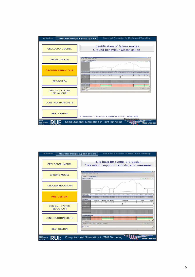
GEOLOGICAL MODELIdentification of failure modes
Ground behaviour Classification
Numerical Simulation for Mechanized TunnellingMotivation Integrated Design Support System
K. Oberste-Ufer, D. Hartmann, A. Steiner, W. Schubert, IACMAG 2008
Computational Simulation in TBM Tunneling
Rule base for tunnel pre-design Excavation, support methods, aux. measures
PRE-DESIGN
GROUND MODEL
GROUND BEHAVIOUR
DESIGN - SYSTEM BEHAVIOUR
BEST DESIGN
CONSTRUCTION COSTS
GEOLOGICAL MODEL
Numerical Simulation for Mechanized TunnellingMotivation Integrated Design Support System
10
Computational Simulation in TBM Tunneling
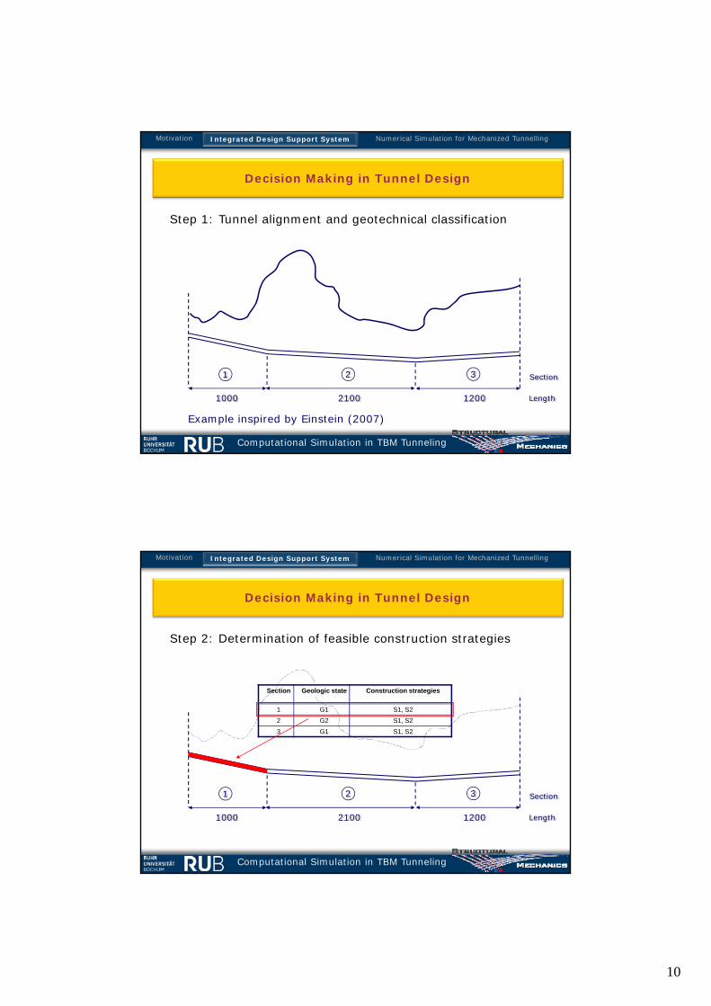
Step 1: Tunnel alignment and geotechnical classification
Length1000 2100 1200
1 2 3 Section
Example inspired by Einstein (2007)
Decision Making in Tunnel Design
Numerical Simulation for Mechanized TunnellingMotivation Integrated Design Support System
Computational Simulation in TBM Tunneling
Step 2: Determination of feasible construction strategies
1000 2100 1200
1 2 3
Length
Section
Section Geologic state Construction strategies
1 G1 S1, S22 G2 S1, S23 G1 S1, S2
Decision Making in Tunnel Design
Numerical Simulation for Mechanized TunnellingMotivation Integrated Design Support System

11
Computational Simulation in TBM Tunneling
Step 3: Assignment of construction strategies
1000 2100 1200
1 2 3
Length
Section
Construction strategy
Construction cost (per unit length) [EUR]
G1 G2S1 3000 3200S2 1500 3900
Decision Making in Tunnel Design
Numerical Simulation for Mechanized TunnellingMotivation Integrated Design Support System
Computational Simulation in TBM Tunneling
Step 4: Selection of “best” solution (w.r.t. expected costs)
1000 2100 1200
1 2 3
Length
Section
where m = total number of construction strategies
n = total number of geologic states
PiG = probability of geologic state i
Cji = cost of construction strategy Sj in geological state Gi
Decision Making in Tunnel Design
Numerical Simulation for Mechanized TunnellingMotivation Integrated Design Support System

12
Computational Simulation in TBM Tunneling
DESIGN - SYSTEM BEHAVIOUR
GROUND MODEL
GROUND BEHAVIOUR
BEST DESIGN
CONSTRUCTION COSTSRESIDUAL RISKS
GEOLOGICAL MODEL
PRE-DESIGN
Numerical Simulation
Numerical Simulation for Mechanized TunnellingMotivation Integrated Design Support System
ekate FEM-simulation model for shield tunnelling
BEFE++ BEM-simulation model for shieldtunnelling
T. Kasper & G. Meschke, Int. J.Numerical and Analytical Methodsin Geomechanics, 2004
G. Meschke, F. Nagel & J. Stascheit, ASCEJournal of Geomechanics, 2010
G. Beer, Technology Innovation inTunnelling, 2008
Computational Simulation in TBM Tunneling
CONSTRUCTION COSTS, RESIDUAL RISKS
GROUND MODEL
GROUND BEHAVIOUR
BEST DESIGN
GEOLOGICAL MODEL
PRE-DESIGN
DESIGN - SYSTEM BEHAVIOUR
Numerical Simulation for Mechanized TunnellingMotivation Integrated Design Support System
MitigationCosts
Std. Building
CostsProb. Class
Conseq.Costs
Proba-bility
Risk AddOns TotalDescription of possible hazards

13
Computational Simulation in TBM Tunneling
BEST DESIGN
GROUND MODEL
GROUND BEHAVIOUR
GEOLOGICAL MODEL
PRE-DESIGN
DESIGN - SYSTEM BEHAVIOUR
CONSTRUCTION COSTS
Numerical Simulation for Mechanized TunnellingMotivation Integrated Design Support System
Computational Simulation in TBM Tunneling
Numerical Simulation model for Mechanized Tunnelling
Integration of simulation software in structured design process
• loss-free flow of data
• user-friendly model generation
• consideration of scattered input parameters
Geological/ geostatistical
modelGroundmodel
Rock Lab data
Rules library
Design data
Time-costmodels
Sensitivities
Project database – data
mining
Risk analysis
Simulation models
IOPT
0
10 000
20 000
30 000
40 000
50 000
60 000
70 000
0 m 1 000 m 2 000 m 3 000 m 4 000 m 5 000 m 6 000 m 7 000 m 8 000 m 9 000 m 10 00
€/m
l
Integrated Design Support SystemMotivation Numerical Simulation for Mechanized Tunnelling

14
Computational Simulation in TBM Tunneling
Components
Geology
Examples
Conclusions
Components of Simulation model
• geological conditions including groundwater• interactions between construction process and soil • realistic simulation of advancement process
1
3
4
5
6
2• surrounding underground
• shield machine
• lining
• hydraulic jacks
• heading face support
• tail gap grouting
1
2
3
4
5
6
Consideration of
Soil
Interactions
Simulation
Applications
Integrated Design Support SystemMotivation Numerical Simulation for Mechanized Tunnelling
Computational Simulation in TBM Tunneling
Components
Geology
Conclusions
From geology to model parameters
Soil
Interactions
Simulation
Applications
Integrated Design Support SystemMotivation Numerical Simulation for Mechanized Tunnelling
Stavropoulou, M., Exadaktylos, G., Saratsis, G., Rock Mech. Rock Engng. 2007
•Underground Engineering: Advanced Simulation and Innovative ConceptsSTRUCTURAL
MECHANICS
Geostatistical modelling (TU Crete, Greece)

15
Computational Simulation in TBM Tunneling
Components
Geology
Soil
Conclusions
Interactions
Simulation
Applications
From geology to model parameters
Integrated Design Support SystemMotivation Numerical Simulation for Mechanized Tunnelling
Model generation: Geology and tunnel alignment
Computational Simulation in TBM Tunneling
Components
Geology
Soil
Conclusions
Modeling of partially saturated soils
RVE
WaterAir
Soil
Three-phase description: pore water, air and soil skeleton
• flow of water and air within the pore voids• coupling with soil displacements
Interactions
Simulation
Applications
Integrated Design Support SystemMotivation Numerical Simulation for Mechanized Tunnelling

16
Computational Simulation in TBM Tunneling
Components
Geology
Soil
Clay and sand model (CASM)[Yu, 1998]
Clay and Sand Model (CASM)
Interactions
Simulation
Conclusions
Applications • Cam-Clay type model• Lode angle dependency, non-associated flow rule• applicable to sandy and clayey soils
Modeling of partially saturated soils
Integrated Design Support SystemMotivation Numerical Simulation for Mechanized Tunnelling
Computational Simulation in TBM Tunneling
Components
Geology
Soil
Interactions
Interactions between TBM and soil
Heading face support modelled by boundary conditions• EPB shield• hydro shield• support by means of compressed air
Simulation
Conclusions
Applications
Integrated Design Support SystemMotivation Numerical Simulation for Mechanized Tunnelling

17
Computational Simulation in TBM Tunneling
Components
Geology
Soil
Interactions
Model for the TBM and contact between shield skin and soil• deformable shield• frictional contact along shield skin• flow of process fluids within steering gap
Generation of TBM
Simulation
Conclusions
Applications
Integrated Design Support SystemMotivation Numerical Simulation for Mechanized Tunnelling
Computational Simulation in TBM Tunneling
Components
Geology
Soil
Interactions
Model for the TBM and contact between shield skin and soil• deformable shield• frictional contact along shield skin• flow of process fluids within steering gap
Simulation
Conclusions
Applications
Integrated Design Support SystemMotivation Numerical Simulation for Mechanized Tunnelling
Generation of TBM

18
Computational Simulation in TBM Tunneling
Components
Geology
Soil
Interactions
• deformable shield• frictional contact along shield skin• Taper considered• flow of process fluids within steering gap
Interactions between TBM and soil
Simulation
Conclusions
Applications
Integrated Design Support SystemMotivation Numerical Simulation for Mechanized Tunnelling
T. Kasper & G. Meschke, Int. J. Num. Anal. Meth. Geomechanics 2004
Contact between TBM and soil
Shield Skin, Taper,Frictional properties
Positions of jacks
Computational Simulation in TBM Tunneling
Components
Geology
Soil
Interactions
Simulation
Conclusions
Model for tail gap grouting• two phase model to take into account pressurization of the
grouting mortar• hydration dependent stiffness and permeability
Applications
Interactions between TBM and soil
Integrated Design Support SystemMotivation Numerical Simulation for Mechanized Tunnelling

19
Computational Simulation in TBM Tunneling
Components
Geology
Soil
Interactions
Simulation
Applications
Conclusions
• continuous mesh adaptation in front of the machine• steering via hydraulic jacks: real kinematics of TBM, simulation
of curved alignment possible
Modelling of the construction process
Simulation Procedure
Integrated Design Support SystemMotivation Numerical Simulation for Mechanized Tunnelling
Computational Simulation in TBM Tunneling
Components
Geology
Soil
Interactions
Simulation
Applications
Conclusions Parallelization – Shared and Distributed Memory Concepts
Parallelized Numerical Simulation
Integrated Design Support SystemMotivation Numerical Simulation for Mechanized Tunnelling

20
Computational Simulation in TBM Tunneling
-0.5
0.0 3 10 40
-10.0
-8.0
-6.0
-4.0
-2.0
0.0
2.0
4.00.
19 1.3
Consolidation
Point A
Point B
Point C
Vert
ical
dis
plac
emen
ts (
cm)
days (log.)
Passing of tail
Tunnel advance
Passingof face
6.0
AB
C
T. KASPER & G. MESCHKE, Int. J. Num. Analy. Meth. Geom. 2004
Tunnel advance in soft soil beneath groundwater table
Integrated Design Support SystemMotivation Numerical Simulation for Mechanized Tunnelling
Computational Simulation in TBM Tunneling
Components
Geology
Soil
Interactions
Simulation
Applications
Conclusions
Compressed Air Intervention
Integrated Design Support SystemMotivation Numerical Simulation for Mechanized Tunnelling
High permeability of soilLow permeability of soilF, NAGEL & G. MESCHKE Int. J. Num. Analy. Meth. Geom. 2009

21
Computational Simulation in TBM Tunneling
-50
-41
-32
-23
-14
-5
4
13
22
31
40 Excess pore water pressure (kN/m2)
TBM without taperTBM with taper
Tunnel advance in soft soil beneath groundwater tableExcess pore water pressure during tunnel drive
Integrated Design Support SystemMotivation Numerical Simulation for Mechanized Tunnelling
Computational Simulation in TBM Tunneling
Components
Geology
Soil
Interactions
Simulation
Conclusions
Applications
Without consideration of grout
With consideration of grout
Distribution of gap width Settlements
(Cooperation with Deltares, The Netherlands)
Fluid flow around TBM
Nagel, Bezuijen, Stascheit & Meschke, EURO:TUN 2009
Computational Simulation in Mechanized Tunneling
Integrated Design Support SystemMotivation Numerical Simulation for Mechanized Tunnelling
F. Nagel, A. Bezuijen, J. Stascheit & G. Meschke, EURO:TUN 2009
22
Computational Simulation in TBM Tunneling
Components
Geology
Soil
Interactions
Simulation
Conclusions
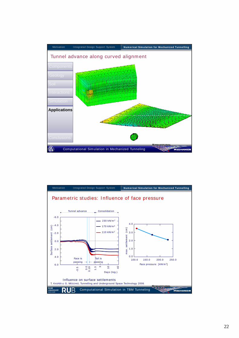
Tunnel advance along curved alignment
Applications
Computational Simulation in Mechanized Tunneling
Integrated Design Support SystemMotivation Numerical Simulation for Mechanized Tunnelling
Computational Simulation in TBM Tunneling
230 kN/m2
170 kN/m2
110 kN/m2
100.0 150.0 200.0 250.0
Face pressure [kN/m2]
Influence on surface settlements
-0.5 0.0 3 10 40
0.19 1.3
0.0
1.0
2.0
3.0
4.0
6.0
4.0
2.0
0.0
-2.0
-4.0
-6.0
Sur
face
set
tlem
ent
(cm
)
Days (log.)
Tail ispassing
Face ispassing
max
. se
ttle
men
t (
cm)
ConsolidationTunnel advance
Parametric studies: Influence of face pressure
Integrated Design Support SystemMotivation Numerical Simulation for Mechanized Tunnelling
T. KASPER & G. MESCHKE, Tunnelling and Underground Space Technology 2006

23
Computational Simulation in TBM Tunneling
180 kN/m2
150 kN/m2
120 kN/m2
-0.5 0.0 3 10 40
0.19 1.3
6.0
4.0
2.0
0.0
-2.0
-4.0
-6.0
Sur
face
set
tlem
ent
(cm
)
Days (log.)
Tail ispassing
Face ispassing
ConsolidationTunnel advance
Influence on surface settlements
110.0 130.0 150.0 190.0Grouting pressure [kN/m2]
170.00.0
1.0
2.0
3.0
4.0
max
. se
ttle
men
t (
cm)
T. KASPER & G. MESCHKE, Tunnelling and Underground Space Technology 2006
Parametric studies: Influence of grouting pressure
Integrated Design Support SystemMotivation Numerical Simulation for Mechanized Tunnelling
Computational Simulation in TBM Tunneling
Motivation
Components
Geology
Soil
Interactions
Simulation
Examples
Conclusions
Summary and Conclusions
Summary
• Tunnelling: A requirement for sustainable development of growing societies, in particular in congested urban areas
• Computational methods in Tunnelling: A pre-requiste for safe and economic design and construction
• Novel process oriented simulation in mechanized tunnelling proposed
• all relevant components and interactions considered

24
Computational Simulation in TBM Tunneling
Motivation
Components
Geology
Soil
Interactions
Simulation
Examples
Conclusions
Application during construction
• tool to investigate consequences of specified process variables
• on-site model update according to monitoring data
• support of steering process in mechanized tunnelling
Application in design stage
• determination of design relevant parameters (settlements, stresses in linings etc.)
• tool to investigate design variants
Summary and Conclusions


![2011 Aug10 Energy Perspectives[1]](https://img.pdfslide.net/doc/110x75/5416057a7bef0a7e3f8b49fc/2011-aug10-energy-perspectives1.jpg)