Embed Size (px)
Citation preview

Mesh Resolution Augmentation using 3D Skin BankWon-Sook Lee*, Andrew Soon
SITE, Faculty of Engineering, University of Ottawa, 800 King Edward Avenue, Ottawa, ON, Canada K1N 6N5
Abstract
We present 3D skin containing information of 3D details of high resolution facial mesh. Our 3D skin
bank is derived from several scanned faces with resolutions up to several million triangles, where even
the pores are clearly visible. We illustrate how to raise the resolution of the geometry of any given low
quality face by making use of 3D skin, where the resulted model’s final resolution is high enough to be
used in computer film industry. Our method can be deployed to produce numerous high resolution
versions of a single low quality face, each bearing different skin characteristics.
Keywords: 3D skin, skin transfer, mesh adaptation, decomposition, mesh parameterization
* Corresponding author, [email protected],
Tel: ++ 1-613-562-5800 ext. 2501
Fax: ++ 1-613-562-5664

1 Introduction
When the first 3D facial model was developed in 1972 [1], it was claimed that only approximately 250 polygons – defined by
about 400 vertices – are necessary to sufficiently approximate a face realistically. However, scanning technology used to capture
real-world objects has evolved in terms of user-friendliness and scanning resolution, making it both easier and more feasible to
obtain superior representations to those yielded by mathematical modeling. Laser scanning (for shape acquisition) and motion
capture are two common ways to obtain the static and dynamic forms of human subjects and they have become more accessible
research tools in many research and commercial labs.
Recent trends show that increasingly higher resolutions of 3D faces are being used for realistic representation. For instance,
about 70 000 vertices were used for a morphable model for the synthesis of 3D faces [2] with the help of Cyberware™ laser
scanning. At this resolution, facial shape structure is visible and individuals are recognizable even in the absence of texture
information. The game “Fight Night Round 3” for the Xbox 360 video game console also showcased extremely high quality face
modeling. The most recent progress in scanning equipment has made it possible to obtain scans of human faces that have
extremely high polygonal counts (10 million triangles) [3] suitable for production use in full-length feature films such as “The
Matrix Reloaded” [4]. The geometry in this production was based on a 100-micron resolution scan of plaster cast molds of the
actors’ faces. Human skin was modeled using a fine-scale, complicated and delicate 3D structure [5], which increased the realism
in the modeling and animation. However, the big drawback of this scanning technology is time and cost. The scanning process for
a human face takes a few days to complete and it is also highly costly.
This paper discusses methodologies to produce extremely high quality models from low quality data. The main idea is to apply
extremely high-quality skin samples from a 3D skin bank to a set of low quality face models obtained from conventional range
data equipment.
We first describe our face database (very high quality faces and low quality faces) and the motivation, and then existing
methodologies related to our work.
1.1 Face Database
1.1.1 Extremely High Quality Data
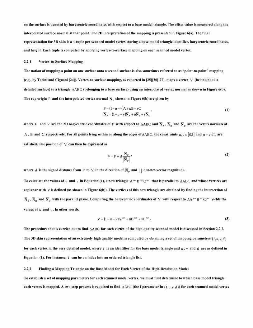
We have collected four very detailed scanned faces, each with a different resolution, as shown in Figure 1. Each individual is
presented with closed eyes and mouth due to the use of plaster modeling in the scanning process. Each model captures only the
facial region of its respective individual and thus lacks information for the rest of the head (including the ears). The faces are of
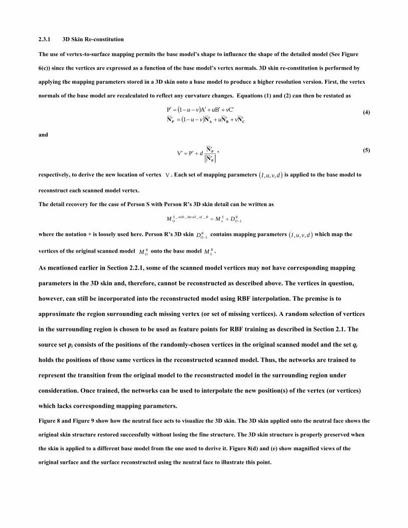
extremely high quality, utilizing millions of triangles to accurately capture the fine and distinct structure of the skin, as shown in
Figure 2(a) and (b).

1.1.2 Low Quality Data
There is a large database for the Civilian American and European Surface Anthropometry Resource Project (CAESARTM)
containing 3D information for thousands of human (male and female) subjects aged 18-65. The scanning process used to obtain
the models captures hundreds of thousands of 3D points on the human body surface in a few seconds. Although the models
provide valuable information such as height and head diameter, a close inspection of the facial region reveals that the data is not
of satisfactory visual quality to be used for other purposes such as computer graphics and animation.
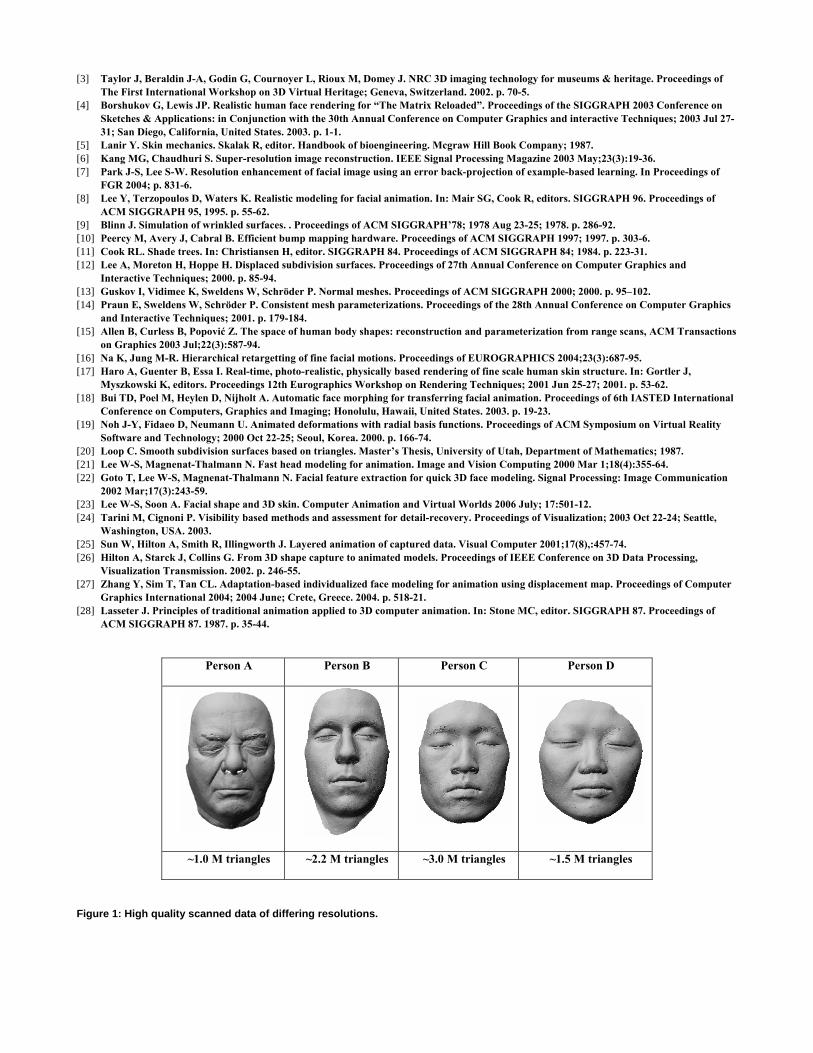
Figure 3 shows some examples from the CAESAR dataset. For our experiments, we retain only the head region (~20K triangles)
of each model and discard the rest of the body. Note that the faces have the correct global shape, but horizontal sliding lines are
quite visible and some faces have many missing points in the facial region. Additionally, some models are incomplete, i.e., holes
are present) in the head and ear regions.
1.2 Motivation
Our research aims to enhance the faces in the CAESAR database to the level of our extremely high quality models so that they
can be used not only for measurement but also for a larger range of applications. The main idea is to assign all the models – both
low and high quality – the same mesh parameterization using a base model so that we can: (a) compile a repository of 3D skin
information for our extremely high resolution models, and (b) apply the skin in our 3D skin bank to the CAESAR data set.
Applying 3D skin to a face in the CAESAR set yields a high quality facial mesh of the subject. This method of skin transfer allows
us to produce a larger dataset, i.e., the same person with several different characteristic skins.
1.3 Literature Review
There have been some trials [6] [7] in image quality augmentation. One of the methods [7] used a morphable 3D human face
database to obtain an approximation of the 3D face in a given facial image by finding optimized coefficients for a linear
combination of morphable models. A high-resolution facial image is obtained by using the optimal coefficients for the linear
combination of the high-resolution prototypes. The original 2D photo is then regenerated at a higher quality. In this case, the
quality of the photo is limited to the resolution of the morphable models.
The resolution of 3D objects can be manipulated using techniques such as Normal Mapping, Displacement Mapping, Displaced
Subdivision Surfaces (DSS), Normal Meshes and Consistent Mesh Parameterizations. The basic techniques behind them are
mesh adaptation [8], multi-resolution and detail restoration.
Normal Mapping [9] [10] is a render-time technique used to create the illusion of surface detail on a surface. The surface’s
normals are replaced completely by those stored in a normal map prior to performing shading calculations and, by doing so,
adds bumps and other surface detail that is absent in the geometrical representation. The UV mapping assigned to the surface
determines which value is retrieved from the image for a particular point on the surface. Normal mapping has grown in
popularity for real-time applications such as video games because it is a relatively inexpensive way of adding a high level of detail

to 3D objects. The major disadvantage of normal mapping is that there are no physical changes to the geometry of the rendered
surface. As a result, bumps that are added by normal mapping do not cast shadows correctly and can ruin the illusion.
Displacement Mapping [11] is a technique used in computer graphics to augment the appearance of a surface. Displacement
mapping yields a more detailed surface by perturbing a base surface along its normals. The perturbation values are retrieved
from the displacement map according to the base surface’s UV map. The offset stored in a pixel is obtained by mapping said pixel
onto the base surface and calculating the distance between the base and the high resolution surface along the surface normal at
the mapped point. The benefits of producing actual deformed geometry (e.g., proper shadow casting and occlusion) are offset by
the cost of the technique.
Lee et al. [12] proposed an efficient representation of high resolution geometry called DSS which essentially represents the high
resolution detail as a scalar displacement field over a smooth domain surface. The DSS representation is constructed in three
steps: building a control model, optimizing the control model and generating the displacement map. First, a low polygon mesh is
produced from the dense geometry. A smooth domain surface is obtained by performing subdivision. This mesh, which serves as
the control model for DSS, is subdivided to obtain a smooth domain surface. The control model is optimized so that the resulting
domain surface more closely approximates the original dense model.
We discuss displacement mapping and DSS in further detail in Section 4.1, comparing these techniques to our presented
methodology.
Several researchers [13] [14] [15] [16] proposed algorithms to generate parameterizations for a set of meshes, some of which are
used for the purposes of multi-resolution modeling and animation. The parameterizations are said to be consistent because they
share a common base domain (point connectivity) and respect the features of the domain, e.g., eyes of a human head. Features
are defined on each mesh in the set using feature detection schemes described in the literature. The feature vertices that result
are used to define patches on the mesh’s surface. The strength of consistent mesh parameterization is in its ability to establish a
common base domain between very different objects and in the use of its results in applications. The exact one-to-one point
correspondence across an entire set of models can then be exploited in applications such as animation, texture transfer and
principal component analysis.
Haro et al. [17] demonstrated the ability to render human faces realistically by properly reproducing the accurate fine-scale
structure of skin as well as the Bidirectional Reflectance Distribution Function (BRDF) properties of skin. Their method captures
the skin structures of small skin samples and uses them to synthesize skin structures for the entire face. Although their method
yields good renderings of human skin, it does not produce high resolution geometry which may be desired for certain
applications such as 3D printing.

2 3D skin bank
We describe first the meaning of 3D skin. 3D skin expresses geometric skin detail as a scalar offset field parameterized over an
aligned, low-resolution facial mesh (referred to as a base model, as shown in Figure 4(c)). Loosely stated, 3D skin is the difference
between the models depicted in Figure 4(a) and Figure 4(c). In this paper, we qualify the CAESAR dataset models (~20K
triangles) and the models defined in this section (~6K triangles) as low-resolution because their resolutions are notably lower
than the models described in Section 1.1.1 which have upward of one million triangles.
2.1 Consistent Facial Mesh Adaptation
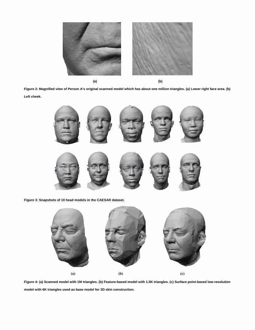
To obtain the base model, we use a two-step mesh adaptation method starting from the generic model shown in Figure 5(a).
Firstly, facial feature point-based adaptation is performed on the generic model to achieve a rough approximation of the high
quality scanned surface. Surface point-based adaptation using cylindrical projection is then applied on the model obtained from
the first step to improve the approximation.
Semi-automatically established 3D feature points on the scanned model, as shown in Figure 5(b), are used to deform the generic
model using Radial Basis Function (RBF) networks [18] [19] creating a coarse matching model as shown in Figure 4(b). The
resulting model is termed the feature-based model.
Two sets of feature points pi and qi, i=1,…,n, are used to train the RBF networks, where the source feature points pi lie on the
generic model and the target feature points qi correspond to features on the target (i.e., high quality) surface as shown in Figure
5(b). After training and weight vector computation, the new positions of the generic model’s non-feature vertices are calculated
by evaluating the RBF networks using said vertices’ initial positions. The feature-based model shares the same topology as the
generic model.
Before applying the second adaptation step, we use Loop’s subdivision scheme [20] designed to achieve a smooth surface to
increase the number of triangles in the feature-based model. We then apply cylindrical projection on the subdivided model to
more closely approximate the scanned surface. The result is shown in Figure 4(c). The details of the surface point-based
adaptation methodology are found in our previous works [21] [22] [23].
Each face in the extremely high quality dataset is processed to obtain a consistent mesh representation where the structure is
inherited from the generic model in Figure 5(a).
2.2 3D Skin Construction
For the high quality models, we derive 3D skin representations by expressing the extremely high quality scanned model as a
scalar offset field over the corresponding low-resolution base model yielded by Section 2.1. We build a map between each vertex
of the high quality model and the surface of the base model by performing vertex-to-surface mapping. Each offset value
represents the distance between a vertex in the high resolution model and a point on the base surface. The location of this point
on the surface is denoted by barycentric coordinates with respect to a base model triangle. The offset value is measured along the
interpolated surface normal at that point. The 2D interpretation of the mapping is presented in Figure 6(a). The final
representation for 3D skin is a 4-tuple per scanned model vertex storing a base model triangle identifier, barycentric coordinates,
and height. Each tuple is computed by applying vertex-to-surface mapping on each scanned model vertex.
2.2.1 Vertex-to-Surface Mapping
The notion of mapping a point on one surface onto a second surface is also sometimes referred to as “point-to-point” mapping
(e.g., by Tarini and Cignoni [24]). Vertex-to-surface mapping, as reported in [25] [26] [27], maps a vertex (belonging to a
detailed surface) to a triangle (belonging to a base surface) using an interpolated vertex normal as shown in Figure 6(b).
The ray origin P and the interpolated vertex normal
V
ABC∆
PN shown in Figure 6(b) are given by
( )( ) CBAP NNNN vuvu
vuvu++−−=
++−−=
1CBA1P , (1)
where u and are the 2D barycentric coordinates of P with respect to v ABC∆ and AN , BN and CN are the vertex normals at
, and C respectively. For all points lying within or along the edges ofA B ABC∆ , the constraints and [ ]1,0, ∈vu 1≤+ vu are
satisfied. The position of V can then be expressed as
P
P
NN
d+= PV , (2)
where d is the signed distance from P to V in the direction of PN and denotes vector magnitude.
To calculate the values of u and v in Equation (1), a new triangle that is parallel to and whose vertices are
coplanar with V is defined (as shown in Figure 6(b)). The vertices of this new triangle are obtained by finding the intersection of
parparpar CBA ABC∆
AN , BN and CN with the parallel plane. Computing the barycentric coordinates of with respect to yields the
values of u and v . In other words,
V parparpar CBA∆
( ) parparpar vuvu CBA1V ++−−= . (3)
The procedure that is carried out to find for each vertex of the high quality scanned model is discussed in Section 2.2.2. ABC∆
The 3D skin representation of an extremely high quality model is computed by obtaining a set of mapping parameters ( )dvuI ,,,
for each vertex in the very detailed model, where I is an identifier for the base model triangle and u , v and are as defined in
Equation (1). For instance,
d
I can be an index into an ordered triangle list.
2.2.2 Finding a Mapping Triangle on the Base Model for Each Vertex of the High-Resolution Model
To establish a set of mapping parameters for each scanned model vertex, we must first determine to which base model triangle
each vertex is mapped. A two-step process is required to find ABC∆ (the I parameter in ( )dvuI ,,, ) for each scanned model vertex

V . The first step consists of accumulating a “bin” of scanned model vertices for each low resolution triangle. Only scanned
model vertices in the vicinity of a triangle are added to its bin to accelerate the checking process. This judgment is made by
checking whether the vertices are situated within an expanded bounding box (see Figure 7) with the size of the expansion user-
definable. Bins are not mutually exclusive so that multiple triangles are checked for each vertex. Note that the purpose of
creating bins is to accelerate the process by limiting the number of vertex-triangle pairs checked in the step that follows.
Once the bins have been populated, the vertex-to-surface mapping scheme is performed iteratively for each vertex-triangle pair
and the best set of mapping parameters is chosen for each scanned model vertex. As the iterative process progresses, each newly
calculated parameter set for a particular scanned model vertex is compared to the incumbent set (if one has been established) for
the same vertex. The incumbent set is the best set of mapping parameters encountered at any given point in the iterative process
and there is at most one incumbent per vertex. A sequence of heuristics is used to decide whether the new set should become the
new incumbent.
1) If the incumbent set’s barycentric coordinates parameters satisfy the constraints [ ]1,0, εvu and , the new set is
removed from consideration if its parameters do not satisfy either constraint.
1≤+ vu
2) The new set is removed from consideration if its barycentric coordinates parameters do not satisfy either [ ]βαε ,,vu or
[ ]βαε ,vu + , where α and β are user-definable.
3) The new set is removed from consideration if its offset parameter exceeds a user-definable threshold.
4) The reconstruction error for each parameter set is the Euclidean distance between the reconstructed vertex and the original
scanned model vertex. The new set is removed from consideration if the reconstruction error exceeds a user-definable threshold.
5) The new set is removed for replacement if the absolute value of its offset parameters is larger than that of the incumbent.
6) The new set is removed from consideration if its associated reconstruction error is larger than that of the incumbent.
7) The new set becomes the incumbent if the preceding heuristics do not remove it from consideration.
After all vertex-triangle pairs are checked, the incumbent set for each vertex is used in the scanned model’s 3D skin. If there is no
incumbent for a vertex, that vertex has no mapping parameters in the 3D skin. Our experiments indicate that 99% of vertices for
most models and 95% for a certain model are mapped during 3D skin construction, depending on the models being used. During
3D skin re-constitution, special post-processing is required for vertices which do not have mapping parameters. Both 3D skin re-
constitution and the post-processing are discussed in Section 2.3.1.
2.3 Visualization of 3D Skin Bank
The 3D skin for extremely high quality models can be visualized on a neutral facial shape. To obtain a neutral shape, we take an
average of a set of base models. As each face inherits the structure from the generic model, each shares exactly the same number
of points and the same triangulation. Thus, a straightforward linear interpolation of 3D coordinates is performed to obtain the
average face.
2.3.1 3D Skin Re-constitution
The use of vertex-to-surface mapping permits the base model’s shape to influence the shape of the detailed model (See Figure
6(c)) since the vertices are expressed as a function of the base model’s vertex normals. 3D skin re-constitution is performed by
applying the mapping parameters stored in a 3D skin onto a base model to produce a higher resolution version. First, the vertex
normals of the base model are recalculated to reflect any curvature changes. Equations (1) and (2) can then be restated as
( )( ) CBAP NNNN ′+′+′−−=′
′+′+′−−=′
′ vuvuvuvu
1CBA1P (4)
and
P
P
NN′
′+′=′ dPV , (5)
respectively, to derive the new location of vertex V . Each set of mapping parameters ( )dvuI ,,, is applied to the base model to
reconstruct each scanned model vertex.
The detail recovery for the case of Person S with Person R’s 3D skin detail can be written as
RLO
SL
RofailwithSO DMM −+=__det__
where the notation + is loosely used here. Person R’s 3D skin contains mapping parameters which map the
vertices of the original scanned model onto the base model .
RLOD − ( dvuI ,,, )
ROM R
LM
As mentioned earlier in Section 2.2.1, some of the scanned model vertices may not have corresponding mapping
parameters in the 3D skin and, therefore, cannot be reconstructed as described above. The vertices in question,
however, can still be incorporated into the reconstructed model using RBF interpolation. The premise is to
approximate the region surrounding each missing vertex (or set of missing vertices). A random selection of vertices
in the surrounding region is chosen to be used as feature points for RBF training as described in Section 2.1. The
source set pi consists of the positions of the randomly-chosen vertices in the original scanned model and the set qi
holds the positions of those same vertices in the reconstructed scanned model. Thus, the networks are trained to
represent the transition from the original model to the reconstructed model in the surrounding region under
consideration. Once trained, the networks can be used to interpolate the new position(s) of the vertex (or vertices)
which lacks corresponding mapping parameters.
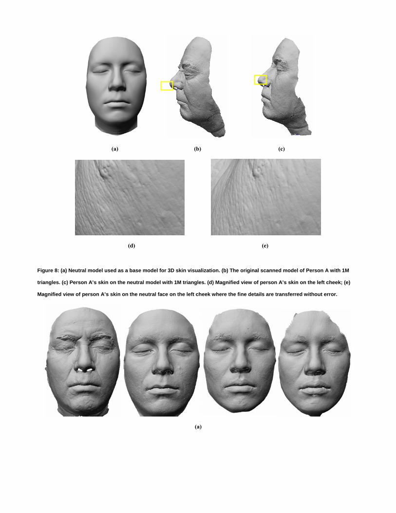
Figure 8 and Figure 9 show how the neutral face acts to visualize the 3D skin. The 3D skin applied onto the neutral face shows the
original skin structure restored successfully without losing the fine structure. The 3D skin structure is properly preserved when
the skin is applied to a different base model from the one used to derive it. Figure 8(d) and (e) show magnified views of the
original surface and the surface reconstructed using the neutral face to illustrate this point.

3 3D Mesh Resolution Augmentation
The method for augmenting the resolution of the low quality faces is to perform skin reconstitution as described in Section 2.3.1
on them. In order to do this, the low quality faces must be restructured using the consistent adaptation algorithm described in
Section 2.1. We derive a set of low resolution models for the low quality dataset as a result.
3.1 Low Quality Model to Base Model
Several examples of low quality data are shown in Figure 10(a) with the corresponding base models shown in Figure 10(b).
Transitioning from the scanned models to the base models removes local noise such as the horizontal sliding lines. Some of the
small holes in the low quality data are also filled in this step as RBF only relies on feature points to deform the generic head shape
and the cylindrical projection moves vertices only when it finds proper candidates on the scanned model. If there is a hole in the
scanned model, the cylindrical projection does not find proper candidates and the position of the base model vertex (after RBF) is
kept as it is; as a result, the holes in the input models are filled automatically.
The choice of the correct resolution of the base model is critical here. There is a trade-off between a preferred higher resolution
for better shape capture and a preferred lower resolution for noise removal. Empirically, we determined that a mesh with about
6K triangles is quite acceptable for satisfying both purposes.
3.2 3D Skin Applied on Low Quality Models
Figure 11(b) and (c) show two resolution augmentation examples of the model in Figure 11(a), where the corresponding low-
resolution base model is the rightmost model in Figure 10(b). The shape is properly captured from the low-quality model and the
3D skin applied on it increases the resolution. The appearance of the augmented face is affected by the choice of 3D skin. For
instance, the 3D skin from Person A is more aged then the 3D skin from Person D. Figure 12 also shows examples of resolution
augmentation for the leftmost and middle models illustrated in Figure 10 where the 3D skin of Persons C and B are used for each
respective model.
3.3 3D Skin on Low Quality Exaggerated Models
Face exaggeration is one of the key animation principles [28], making output more attractive and distinctive by exaggerating the
shape, color, emotion, or actions of a character. A 3D facial-caricaturing algorithm is usually applied on a homogeneously
structured (morphable) model (with approximately 20~70K triangles) to exaggerate the distinctive information both at a local
level by exaggerating small facial creases into wrinkles, and at a more global level to produce a more pronounced skull [2].
As all the faces share the same structure, it is straightforward to make exaggeration using a standard vector-based method. The
purpose of exaggeration is to ensure the identity of the human subject is emphasized after 3D skin augmentation. We select the
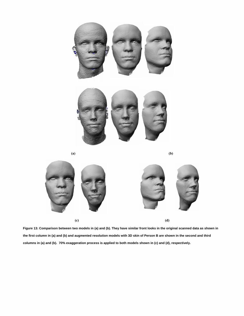
two most similar looking models in the low quality dataset. Figure 13 shows the effect of exaggeration where two models become

a lot more designable with 70% exaggeration as it emphasizes the characteristics of each individual. It is possible to control the
degree of exaggeration and the right degree works to emphasize the identity without losing it.
Standard exaggeration [2] can only exaggerate the morphable structure. It cannot be performed directly on the scanned faces as
they do not all share a common structure. Our exaggeration method is more general because we can also produce an exaggerated
version of the extremely high resolution scanned model even though the detailed faces do not share the same structure. In other
words, it is possible to exaggerate with or without 3D skin. The key to this possibility is to decompose the model into shape
(structurally consistent) and 3D skin, then apply standard exaggeration on only the shape and then finally recover the highly
detailed skin structure.
4 Discussion
4.1 The Difference from Displacement Mapping and DSS
Figure 14 shows the comparison between the respective results produced by the popular detail representation technique
Displacement Mapping and our methodology. Displacement mapping and DSS, where displacement mapping is used eventually
on the coarse base mesh, are not accurate enough to restore the quality of the extremely high resolution surface unless they use
an exceptionally high resolution. Displacement mapping and DSS approximate the very detailed original surface by sampling it
at regular intervals and they are designed to capture quite accurate approximations for lower resolution models. Usually,
displacement mapping is successful because many mesh objects are coarser in resolution than the pixel resolution used in
displacement UV mapping to capture the details. However, our skin models are of extremely high resolution where the face
region has upward of one million triangles. In order to capture the details using approximation, we need to use very high
resolution displacement mapping. Our experiment shows in Figure 14(b) that displacement mapping at a resolution of 2048x2048
( ~4M pixels) failed to capture the exact structure of certain skin regions of a face which has about 1M triangles. These triangles
are irregular and displacement mapping’s regular intervals are not guaranteed to capture the irregular triangle details unless we
operate at a resolution much higher than the triangle mesh resolution. Displacement mapping showed quite acceptable results
for areas in which the mesh distribution is less dense or more regular such as some parts of the forehead, but it failed to capture
the details where the mesh shows fine details with a high degree of irregularity. It is possible to raise the displacement mapping
resolution to capture all the irregular points using regular intervals, but in that case, it raises the question of cost and time
effectiveness of using a very high resolution displacement map. Our methods reconstruct extremely highly dense irregular
meshes by capturing only the existing vertices; hence, it does not raise the question of sampling frequency that displacement
mapping does. Figure 15 depicts the limitation of displacement mapping.

4.2 Flexibility
The presented methods for resolution augmentation of 3D object show experiments optimized for the human face. However, the
basic methodology is applicable for any object with desired adaptation for certain steps in the consistent mesh parameterization.
Consistent mesh parameterization described in Section 2.1 is specialized for human faces in the sense that the feature points that
are used were carefully defined for the purpose of identifying an individual. The use of cylindrical projection for shape
refinement is also often used for human heads because of their somewhat cylindrical shape. When an object is different from
simple geometry, we can adapt more general methods such as error minimization optimization [15], which usually takes longer
calculation time with iteration of several error parameters. So it is the choice between a rapid dedicated algorithm tailored for a
certain fixed shape and a general purpose algorithm which works on general objects depending on the application. Surface
approximation using RBF networks, 3D skin construction using vertex-to-surface mapping, 3D skin transfer onto another mesh
model, 3D model reconstruction and 3D mesh model exaggeration are general-purpose ideas and techniques that can be used for
other classes of objects.
4.3 Current Limitations and Future Work
Our experiments show successful results to raise the resolution of given low quality facial mesh data. However, there are some
limitations to discuss and they are as follows:
(i) Only the face region of the 3D skin used to augment the given facial mesh is retained. One of the main reasons we do not
include the whole head region is because of ears. As we do not have enough data to estimate the proper ear shape, it is not
straightforward to restore the ear regions with the methods proposed in this paper. Special algorithms are needed to treat only
the ear areas. One such algorithm is to use only feature point-based adaptation without going through surface point-based
adaptation with a database of ears. Then, the head region can also be kept with proper ears.
(ii) The faces which contribute to the 3D skin bank have closed eyes due to the very accurate as well as very heavy scanning
process. However, the low-quality models have open eyes and our current experiments do not include eye treatment. The eyes of
the generic model can be controlled to be either open or closed by an animation system as the generic model has an embedded
animation structure. One possible strategy is to use closed-eyed scanned models and a closed-eyed generic model to compile the
skin database. In this case, we would use an open-eyed generic model to produce the base models since the low quality models
have open eyes. When we apply the 3D skin onto the open-eyed low resolution models, the augmented faces should also be open-
eyed because the augmentation result depends on the condition of the base model.
(iii) The human face in real-life is equipped with geometry as well as skin color information. The faces shown here do not have
texture information. The skin bank is considered to provide the color information. The conventional 2D face texture mapping
used in coarse face models contains psudo-3D information such as 3D looking in a specific view while 2D looking in other views.

As our 3D skin already provides detailed 3D-geometry structure, the true Skin color is to be built by the amount and type of the
pigment melanin in the skin.
5 Conclusion
A high quality, high resolution model is necessary for certain applications such as films, high quality computer games and virtual
reality. It also gives us the freedom to control resolution for our needs. However, the time and financial costs of obtaining high
quality models are significant. We have shown how to raise the resolution of a low quality model using a 3D skin databank in an
efficient way in terms of time, cost and resources. Once the 3D skin bank is created, any skin in the bank can be chosen to
augment the resolution of the low quality model.
The methodologies make use of mesh adaptation with a generic model to extract the shape of a low quality model where the local
noise of the model is removed as well.
3D skin is constructed using decomposition of extremely detailed 3D scans into dense offsets and overall 3D geometry. The 3D
geometry shares the same structure with the generic model used for the low quality models, which enables the transfer of dense
geometric detail from one face to another.
The time required to construct the 3D skin for a 1M triangle face using the current base model with 6K triangles is about 11
seconds. Additionally, execution time for 3D skin re-constitution is fairly constant at about 2 seconds for all 3D skin cases on a PC
equipped with a 2.6 GHz Opteron 252 processor. Times can vary if the base model resolution is changed, e.g., longer execution
time for a higher resolution base model.
Even though a large database is not necessary for our system, a larger 3D skin bank is preferred by users to offer a wider
selection of skins from which to choose. In our experiments, we find that Asian skin (thicker lips) works better to provide 3D skin
on Asian and African ethnic groups than Caucasian skin (normally thinner lips). Ethnicity, age correspondence as well as gender
correspondence may give more natural looking results when we apply 3D skin on low quality models. 3D-based biomechanical
simulation and visualization of skin is the future direction of this 3D skin research.
Acknowledgements
We would like to thank XYZ RGB Inc. for providing us with its scanning service and data sets for our face database. We wish to
acknowledge the use of faces from the CAESAR database in our own low quality face collection. We would also like to
acknowledge the contributions of Lijia Zhu and Quan Zhou to this research. This research is partly supported by NSERC
DISCOVERY and ORNEC grants.
References
[1] Parke FI. Computer generated animation of faces. Proceedings of The ACM Annual Conference - Volume 1; 1972 Aug 1-1; Boston, Massachusetts, United States. 1972. p. 451-7.
[2] Blanz V, Vetter T. A morphable model for the synthesis of 3D faces. Proceedings of ACM SIGGRAPH‘99, 1999. p. 187-94.
[3] Taylor J, Beraldin J-A, Godin G, Cournoyer L, Rioux M, Domey J. NRC 3D imaging technology for museums & heritage. Proceedings of The First International Workshop on 3D Virtual Heritage; Geneva, Switzerland. 2002. p. 70-5.
[4] Borshukov G, Lewis JP. Realistic human face rendering for “The Matrix Reloaded”. Proceedings of the SIGGRAPH 2003 Conference on Sketches & Applications: in Conjunction with the 30th Annual Conference on Computer Graphics and interactive Techniques; 2003 Jul 27-31; San Diego, California, United States. 2003. p. 1-1.
[5] Lanir Y. Skin mechanics. Skalak R, editor. Handbook of bioengineering. Mcgraw Hill Book Company; 1987. [6] Kang MG, Chaudhuri S. Super-resolution image reconstruction. IEEE Signal Processing Magazine 2003 May;23(3):19-36. [7] Park J-S, Lee S-W. Resolution enhancement of facial image using an error back-projection of example-based learning. In Proceedings of
FGR 2004; p. 831-6. [8] Lee Y, Terzopoulos D, Waters K. Realistic modeling for facial animation. In: Mair SG, Cook R, editors. SIGGRAPH 96. Proceedings of
ACM SIGGRAPH 95, 1995. p. 55-62. [9] Blinn J. Simulation of wrinkled surfaces. . Proceedings of ACM SIGGRAPH’78; 1978 Aug 23-25; 1978. p. 286-92. [10] Peercy M, Avery J, Cabral B. Efficient bump mapping hardware. Proceedings of ACM SIGGRAPH 1997; 1997. p. 303-6. [11] Cook RL. Shade trees. In: Christiansen H, editor. SIGGRAPH 84. Proceedings of ACM SIGGRAPH 84; 1984. p. 223-31. [12] Lee A, Moreton H, Hoppe H. Displaced subdivision surfaces. Proceedings of 27th Annual Conference on Computer Graphics and
Interactive Techniques; 2000. p. 85-94. [13] Guskov I, Vidimee K, Sweldens W, Schröder P. Normal meshes. Proceedings of ACM SIGGRAPH 2000; 2000. p. 95–102. [14] Praun E, Sweldens W, Schröder P. Consistent mesh parameterizations. Proceedings of the 28th Annual Conference on Computer Graphics
and Interactive Techniques; 2001. p. 179-184. [15] Allen B, Curless B, Popović Z. The space of human body shapes: reconstruction and parameterization from range scans, ACM Transactions
on Graphics 2003 Jul;22(3):587-94. [16] Na K, Jung M-R. Hierarchical retargetting of fine facial motions. Proceedings of EUROGRAPHICS 2004;23(3):687-95. [17] Haro A, Guenter B, Essa I. Real-time, photo-realistic, physically based rendering of fine scale human skin structure. In: Gortler J,
Myszkowski K, editors. Proceedings 12th Eurographics Workshop on Rendering Techniques; 2001 Jun 25-27; 2001. p. 53-62. [18] Bui TD, Poel M, Heylen D, Nijholt A. Automatic face morphing for transferring facial animation. Proceedings of 6th IASTED International
Conference on Computers, Graphics and Imaging; Honolulu, Hawaii, United States. 2003. p. 19-23. [19] Noh J-Y, Fidaeo D, Neumann U. Animated deformations with radial basis functions. Proceedings of ACM Symposium on Virtual Reality
Software and Technology; 2000 Oct 22-25; Seoul, Korea. 2000. p. 166-74. [20] Loop C. Smooth subdivision surfaces based on triangles. Master’s Thesis, University of Utah, Department of Mathematics; 1987. [21] Lee W-S, Magnenat-Thalmann N. Fast head modeling for animation. Image and Vision Computing 2000 Mar 1;18(4):355-64. [22] Goto T, Lee W-S, Magnenat-Thalmann N. Facial feature extraction for quick 3D face modeling. Signal Processing: Image Communication
2002 Mar;17(3):243-59. [23] Lee W-S, Soon A. Facial shape and 3D skin. Computer Animation and Virtual Worlds 2006 July; 17:501-12. [24] Tarini M, Cignoni P. Visibility based methods and assessment for detail-recovery. Proceedings of Visualization; 2003 Oct 22-24; Seattle,
Washington, USA. 2003. [25] Sun W, Hilton A, Smith R, Illingworth J. Layered animation of captured data. Visual Computer 2001;17(8),:457-74. [26] Hilton A, Starck J, Collins G. From 3D shape capture to animated models. Proceedings of IEEE Conference on 3D Data Processing,
Visualization Transmission. 2002. p. 246-55. [27] Zhang Y, Sim T, Tan CL. Adaptation-based individualized face modeling for animation using displacement map. Proceedings of Computer
Graphics International 2004; 2004 June; Crete, Greece. 2004. p. 518-21. [28] Lasseter J. Principles of traditional animation applied to 3D computer animation. In: Stone MC, editor. SIGGRAPH 87. Proceedings of
ACM SIGGRAPH 87. 1987. p. 35-44.
Person A Person B Person C Person D
~1.0 M triangles ~2.2 M triangles ~3.0 M triangles ~1.5 M triangles
Figure 1: High quality scanned data of differing resolutions.
(a) (b)
Figure 2: Magnified view of Person A’s original scanned model which has about one million triangles. (a) Lower right face area. (b)
Left cheek.
Figure 3: Snapshots of 10 head models in the CAESAR dataset.
(a) (b) (c)
Figure 4: (a) Scanned model with 1M triangles. (b) Feature-based model with 1.5K triangles. (c) Surface point-based low-resolution
model with 6K triangles used as base model for 3D skin construction.
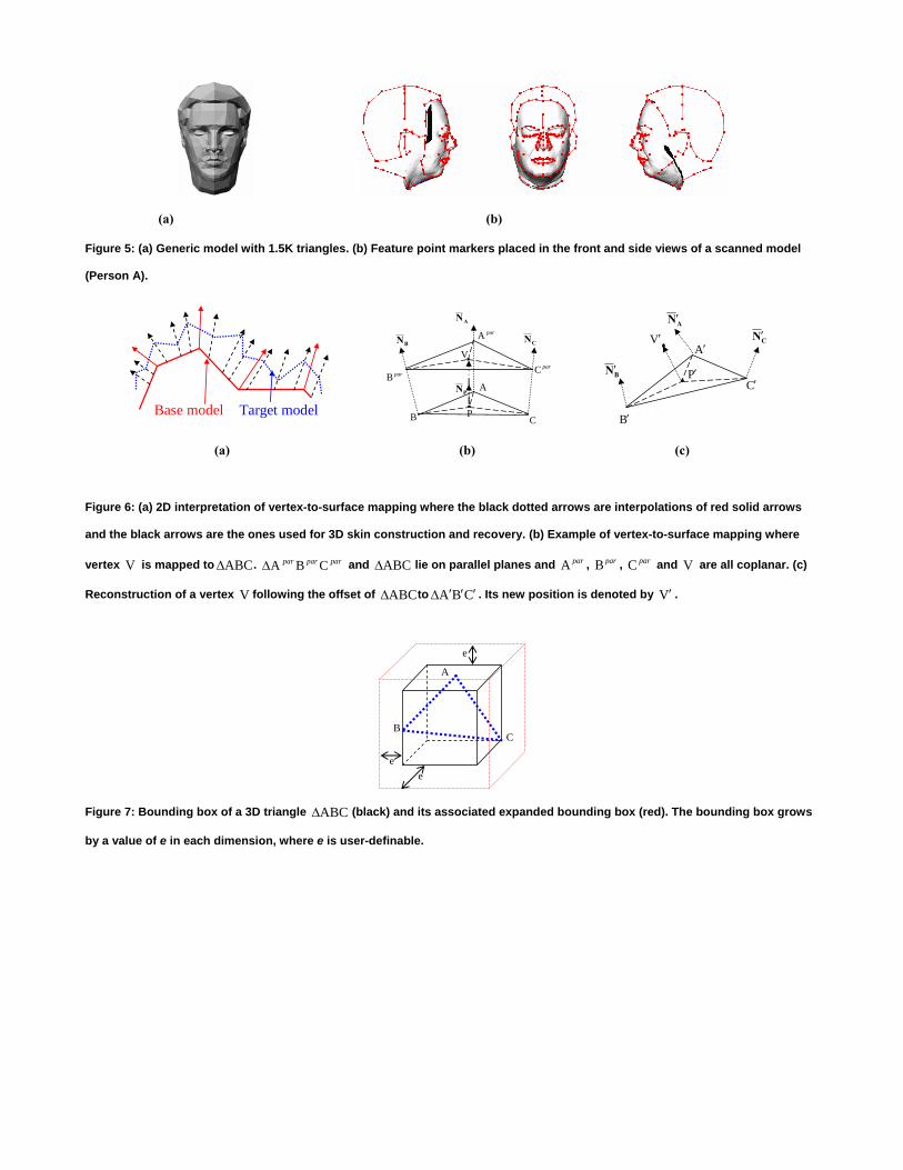
(a) (b)
Figure 5: (a) Generic model with 1.5K triangles. (b) Feature point markers placed in the front and side views of a scanned model
(Person A).
Base model Target model
AN
BN CN
A
B CP
V
parB
parA
PN
parC
AN′
BN′
CN′A′
B′
C′P′
V′
(a) (b) (c)
Figure 6: (a) 2D interpretation of vertex-to-surface mapping where the black dotted arrows are interpolations of red solid arrows
and the black arrows are the ones used for 3D skin construction and recovery. (b) Example of vertex-to-surface mapping where
vertex V is mapped to . and ABC∆ parparpar CBA∆ ABC∆ lie on parallel planes and , , and are all coplanar. (c)
Reconstruction of a vertex following the offset of
parA parB parC V
V ABC∆ to CBA ′′′∆ . Its new position is denoted by . V′
A
BC
ee
e
Figure 7: Bounding box of a 3D triangle (black) and its associated expanded bounding box (red). The bounding box grows
by a value of e in each dimension, where e is user-definable.
ABC∆
(a) (b) (c)
(d) (e)
Figure 8: (a) Neutral model used as a base model for 3D skin visualization. (b) The original scanned model of Person A with 1M
triangles. (c) Person A’s skin on the neutral model with 1M triangles. (d) Magnified view of person A’s skin on the left cheek; (e)
Magnified view of person A’s skin on the neutral face on the left cheek where the fine details are transferred without error.
(a)
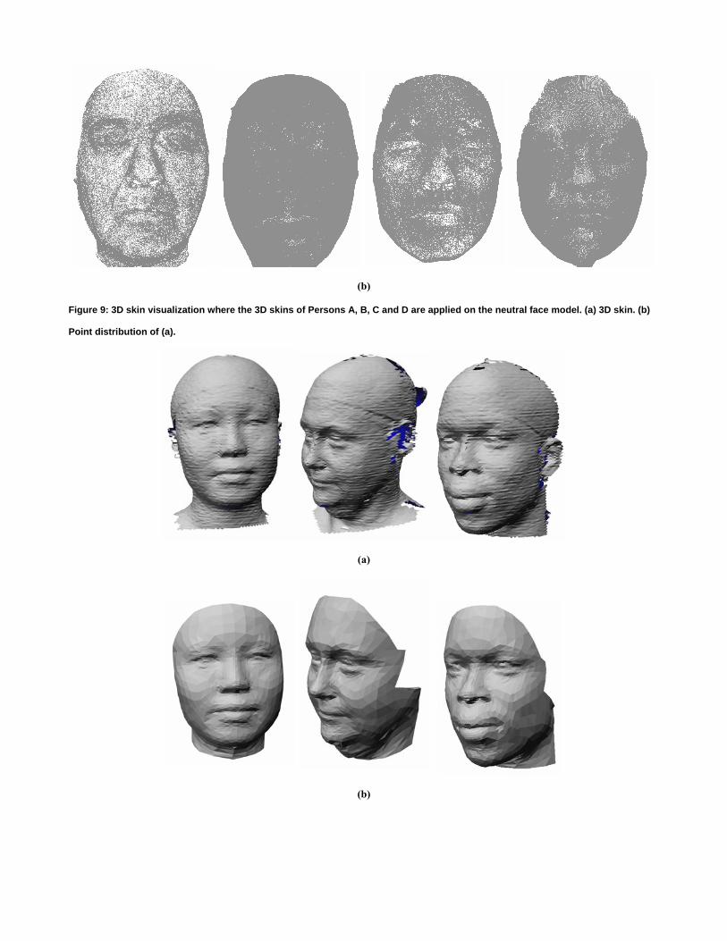
(b)
Figure 9: 3D skin visualization where the 3D skins of Persons A, B, C and D are applied on the neutral face model. (a) 3D skin. (b)
Point distribution of (a).
(a)
(b)
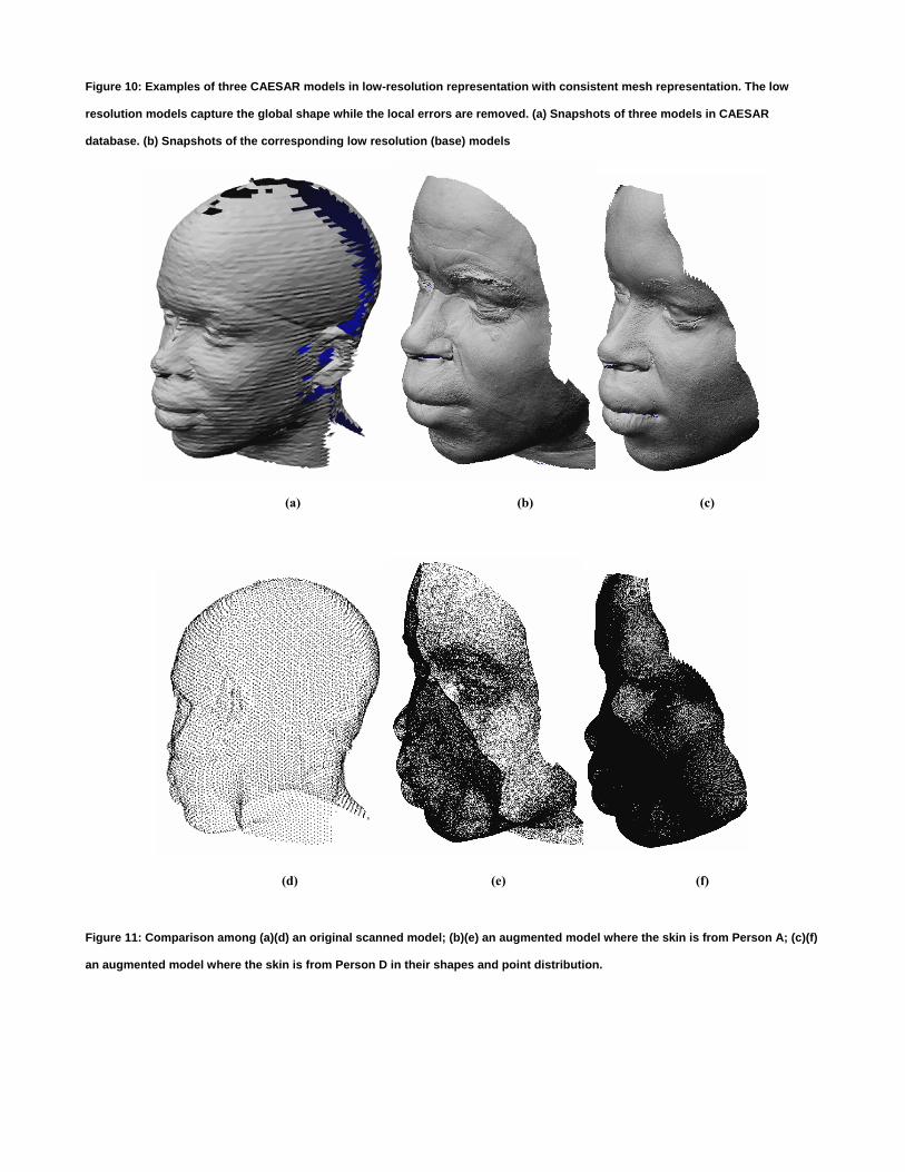
Figure 10: Examples of three CAESAR models in low-resolution representation with consistent mesh representation. The low
resolution models capture the global shape while the local errors are removed. (a) Snapshots of three models in CAESAR
database. (b) Snapshots of the corresponding low resolution (base) models
(a) (b) (c)
(d) (e) (f)
Figure 11: Comparison among (a)(d) an original scanned model; (b)(e) an augmented model where the skin is from Person A; (c)(f)
an augmented model where the skin is from Person D in their shapes and point distribution.

(a)
(b)
Figure 12: Comparison between original low quality data (left) and augmented data (right). (a) Augmented using Person C’s skin.
(b) Augmented using Person B’s skin.
(a) (b)
(c) (d)
Figure 13: Comparison between two models in (a) and (b). They have similar front looks in the original scanned data as shown in
the first column in (a) and (b) and augmented resolution models with 3D skin of Person B are shown in the second and third
columns in (a) and (b). 70% exaggeration process is applied to both models shown in (c) and (d), respectively.
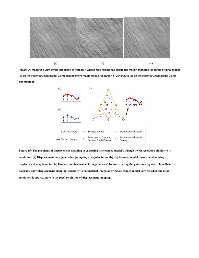
(a) (b) (c)
Figure 14: Magnified view of the left cheek of Person A whose face region has about one million triangles (a) on the original model
(b) on the reconstructed model using displacement mapping at a resolution of 2048x2048 (c) on the reconstructed model using
our methods.
(c)
(b)
Low-res Model Scanned Model
Surface Normal Point used to Capture Scanned Model Vertex
Reconstructed Model Vertex
(a)
Reconstructed Model
Figure 15: The problems of displacement mapping in capturing the scanned model’s triangles with resolution similar to its
resolution. (a) Displacement map generation (sampling at regular intervals). (b) Scanned model reconstruction using
displacement map from (a). (c) Our method to construct irregular mesh by constructing the points one by one. These three
diagrams show displacement mapping’s inability to reconstruct irregular original scanned model vertices when the mesh
resolution is approximate to the pixel resolution of displacement mapping.