Embed Size (px)
Citation preview

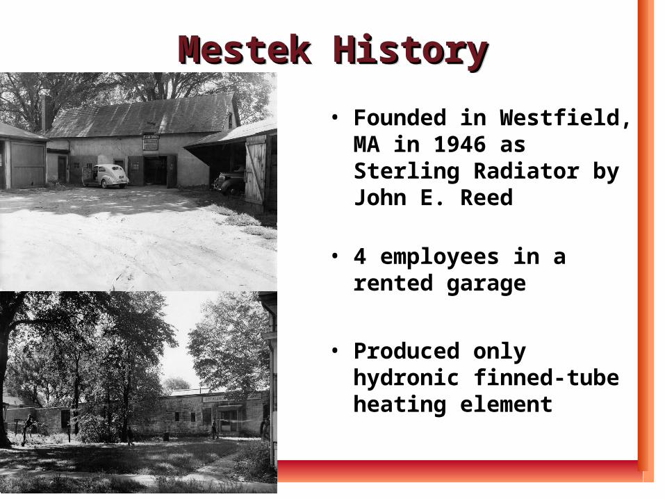
Mestek HistoryMestek HistoryMestek HistoryMestek History
• Founded in Westfield, MA in 1946 as Sterling Radiator by John E. Reed
• 4 employees in a rented garage
• Produced only hydronic finned-tube heating element
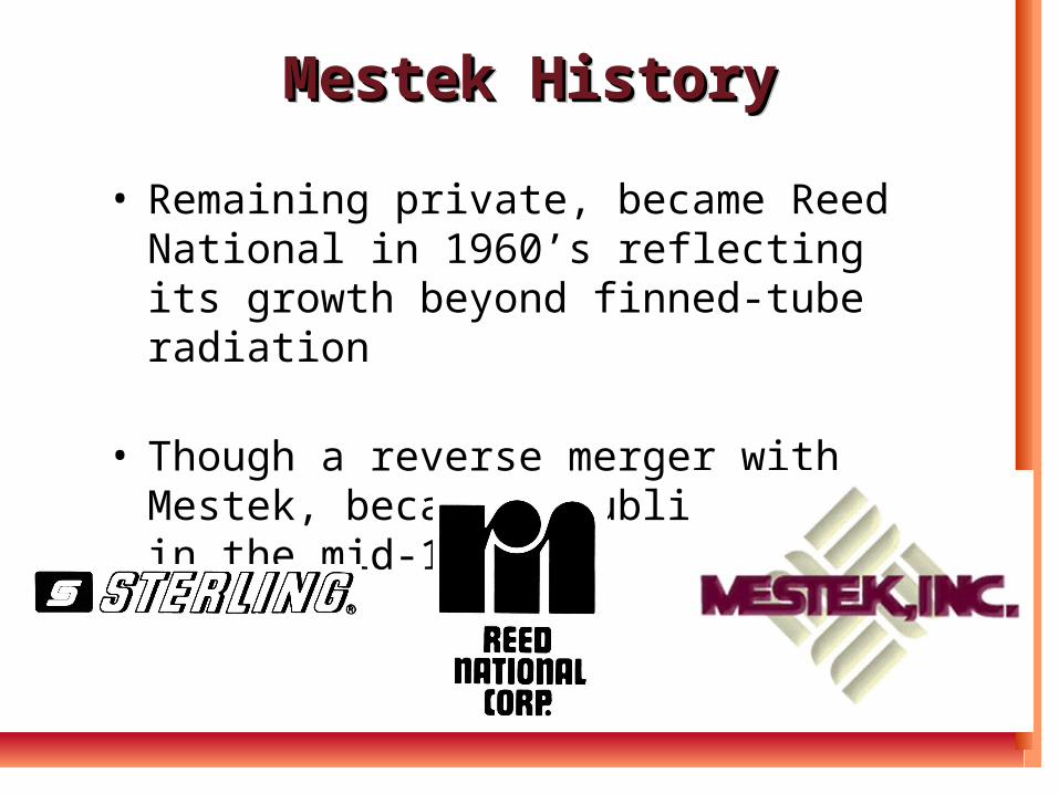
Mestek HistoryMestek HistoryMestek HistoryMestek History
• Remaining private, became Reed National in 1960’s reflecting its growth beyond finned-tube radiation
• Though a reverse merger with Mestek, became a public company in the mid-1980’s
HVAC HVAC ActivitiesActivities
HVAC HVAC ActivitiesActivities
PLUMBING/HEATING WHOLESALERS
PLUMBING/HEATING WHOLESALERS
MECHANICAL, SHEET METAL & GENERAL CONTRACTORS
MECHANICAL, SHEET METAL & GENERAL CONTRACTORS
HVAC DISTRIBUTORS
PLUMBING/HEATING
WHOLESALERS
HVAC HVAC ActivitiesActivities
HVAC HVAC ActivitiesActivities
OEM National AccountsOEM National AccountsOEM National AccountsOEM National Accounts
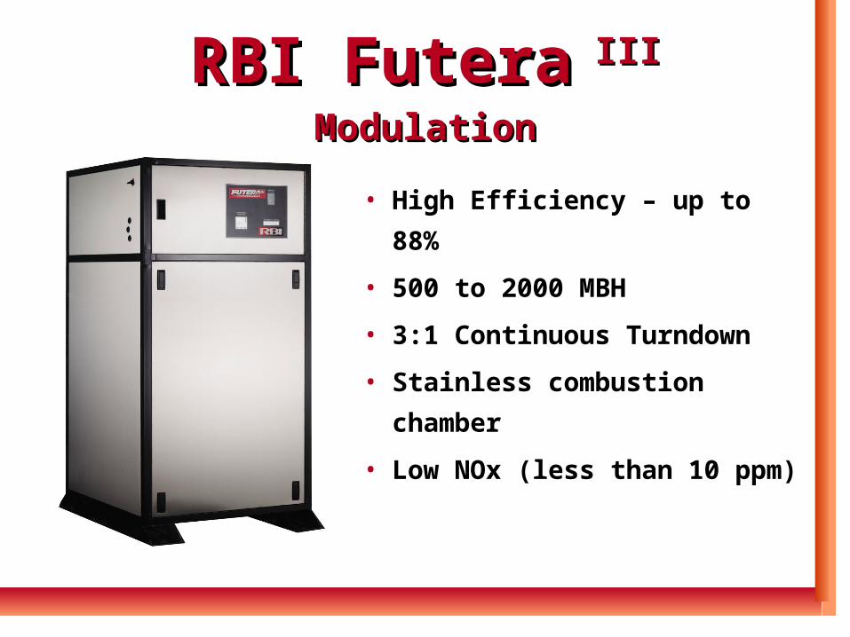
RBI FuteraRBI Futera III Modulation III Modulation
• High Efficiency – up to 88%
• 500 to 2000 MBH
• 3:1 Continuous Turndown
• Stainless combustion
chamber
• Low NOx (less than 10 ppm)
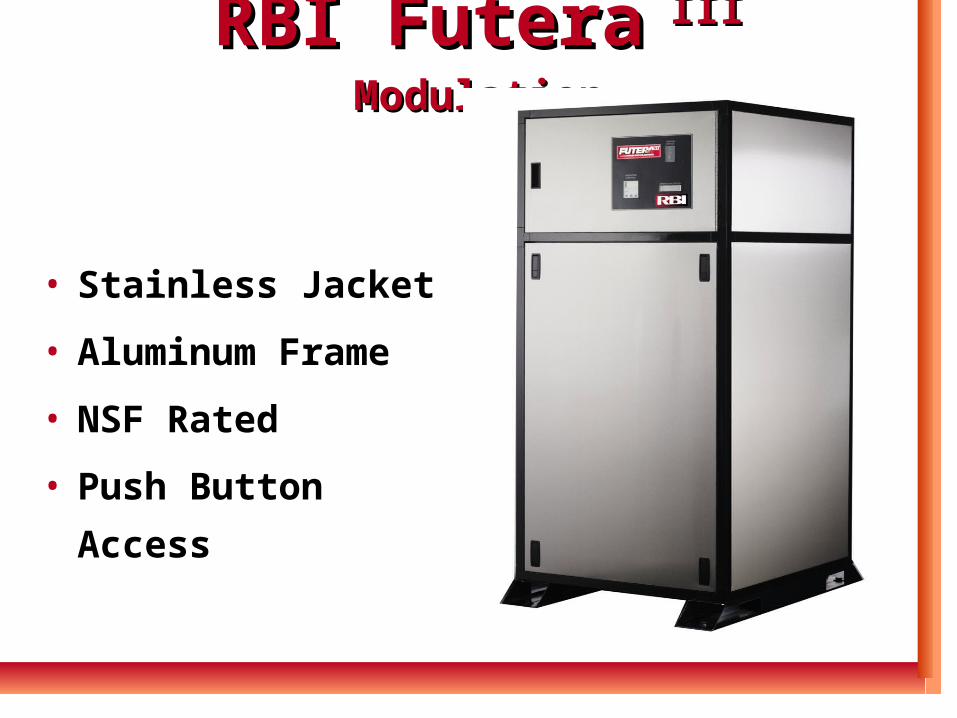
RBI FuteraRBI Futera III Modulation III Modulation
• Stainless Jacket
• Aluminum Frame
• NSF Rated
• Push Button Access
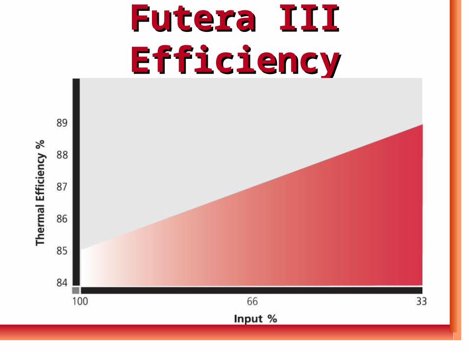
Futera III EfficiencyFutera III Efficiency
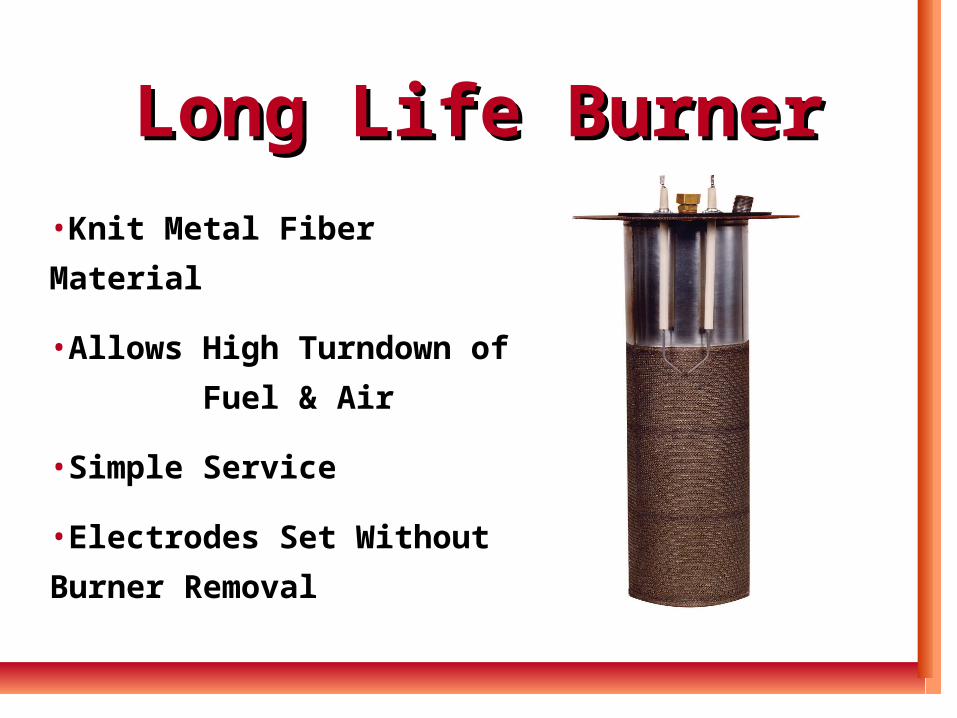
Long Life BurnerLong Life Burner
•Knit Metal Fiber Material
•Allows High Turndown of
Fuel & Air
•Simple Service
•Electrodes Set Without
Burner Removal
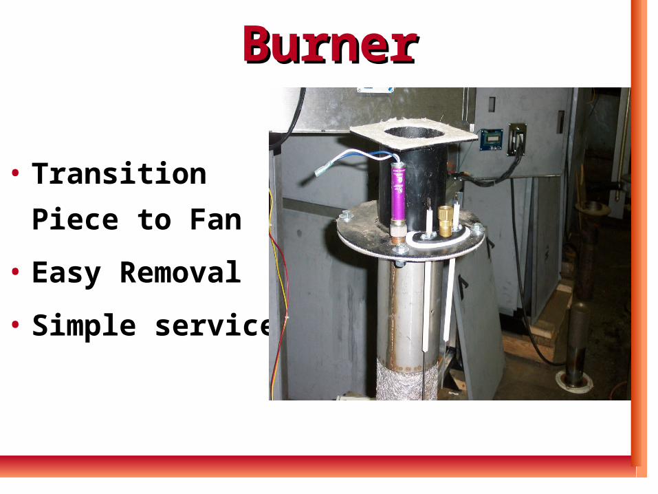
BurnerBurner
• Transition Piece
to Fan
• Easy Removal
• Simple service
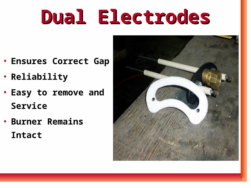
Dual ElectrodesDual Electrodes
• Ensures Correct Gap
• Reliability
• Easy to remove and
Service
• Burner Remains Intact
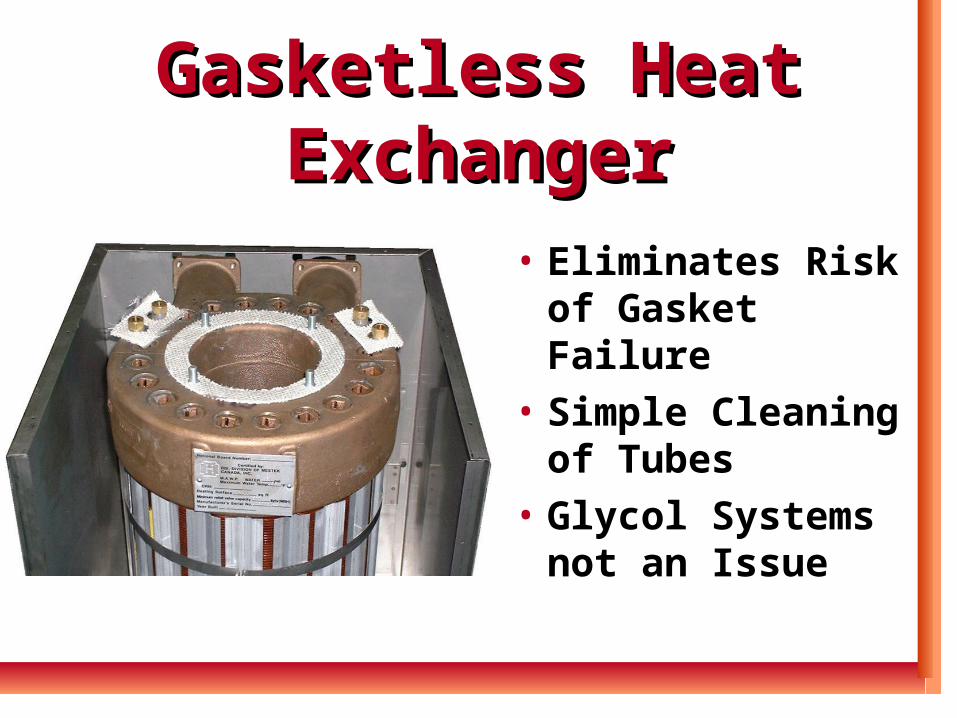
Gasketless Heat Gasketless Heat ExchangerExchanger
• Eliminates Risk of Gasket Failure
• Simple Cleaning of Tubes
• Glycol Systems not an Issue
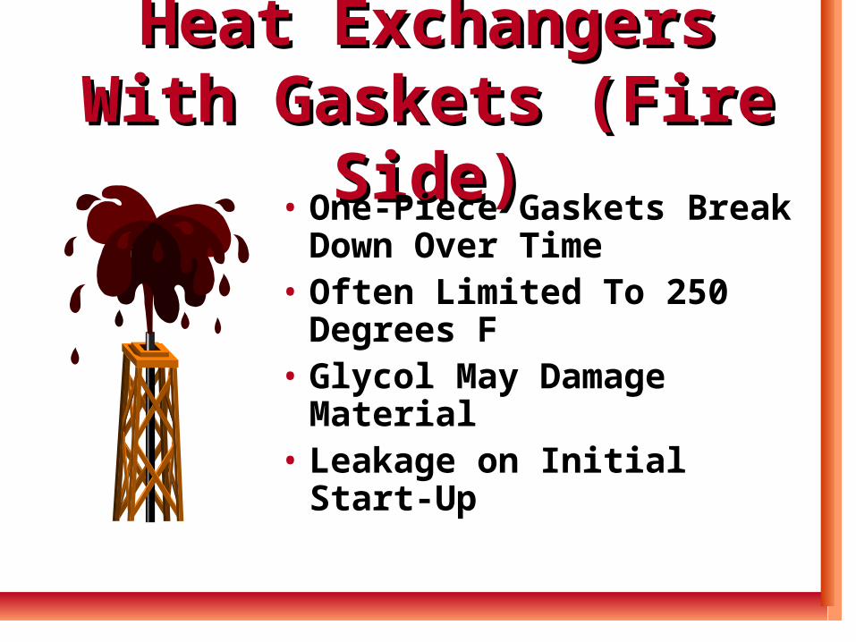
Heat Exchangers With Heat Exchangers With Gaskets (Fire Side)Gaskets (Fire Side)
• One-Piece Gaskets Break Down Over Time
• Often Limited To 250 Degrees F
• Glycol May Damage Material
• Leakage on Initial Start-Up
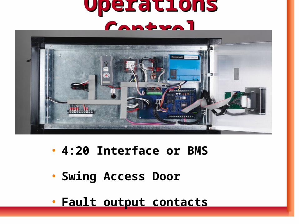
• 4:20 Interface or BMS
• Swing Access Door
• Fault output contacts
Operations ControlOperations Control
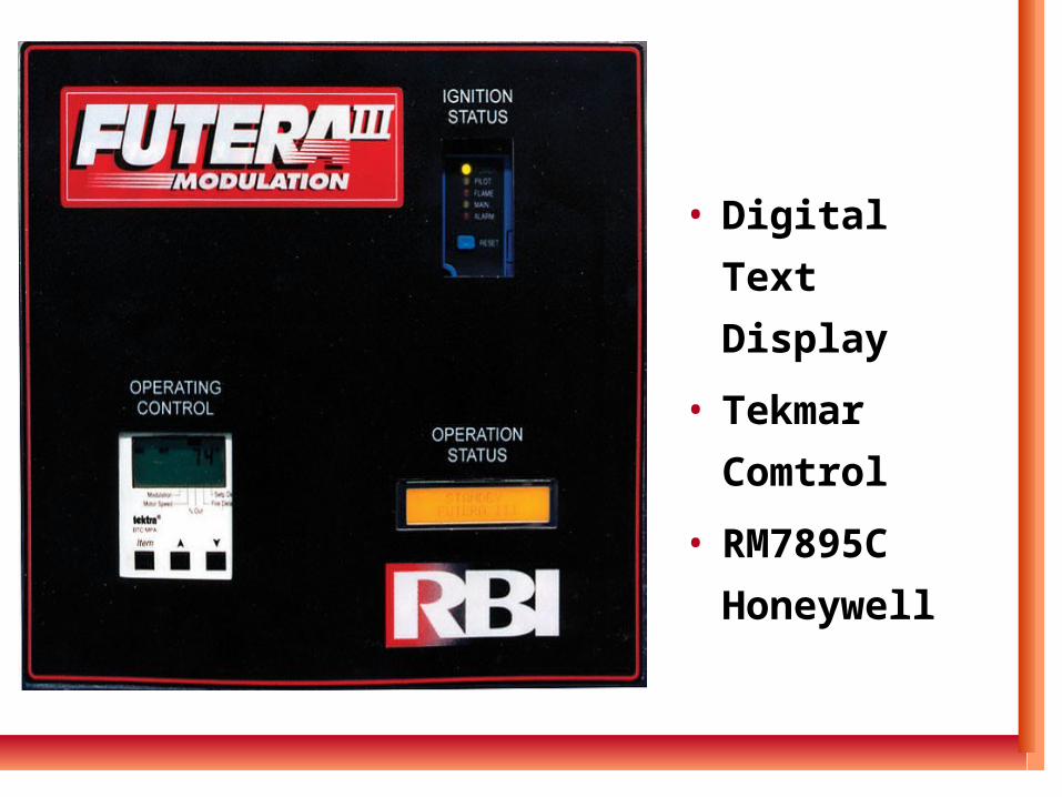
• Digital Text
Display
• Tekmar
Comtrol
• RM7895C
Honeywell
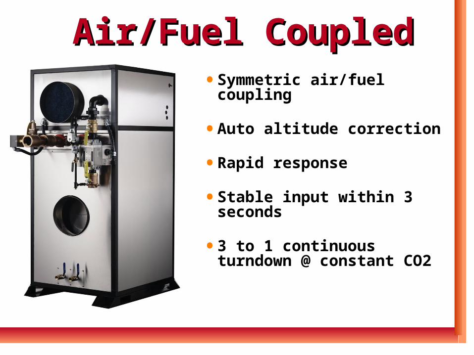
• Symmetric air/fuel coupling
• Auto altitude correction
• Rapid response
• Stable input within 3 seconds
• 3 to 1 continuous turndown @ constant CO2
Air/Fuel CoupledAir/Fuel Coupled
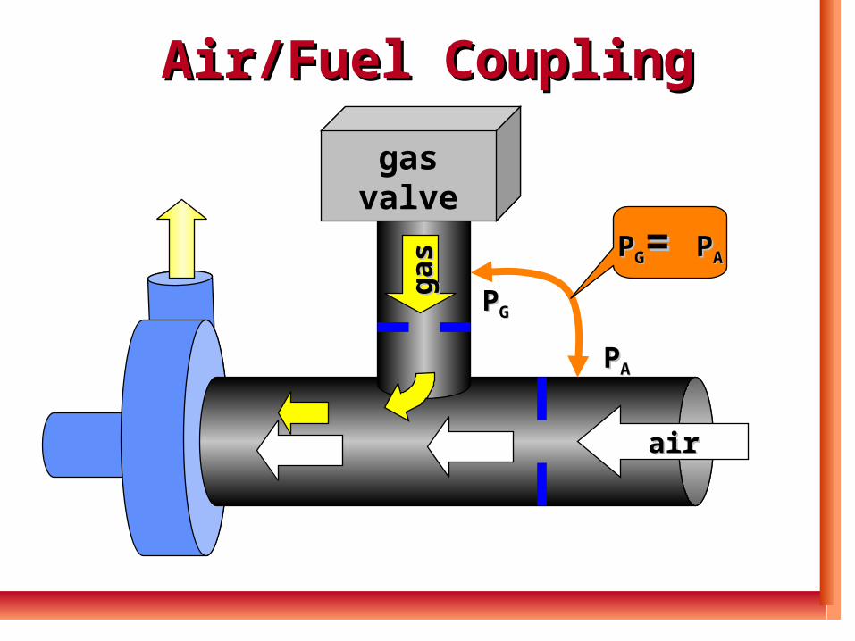
Air/Fuel CouplingAir/Fuel Coupling
gasgasvalvevalve
gas
gas
PPGG= = PPAA
PPAA
PPGG
airair
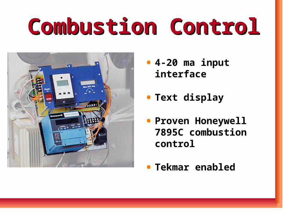
Combustion ControlCombustion Control
• 4-20 ma input interface
• Text display
• Proven Honeywell 7895C combustion control
• Tekmar enabled
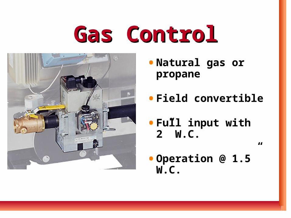
Gas ControlGas Control• Natural gas or
propane
• Field convertible
• Full input with 2” W.C.
• Operation @ 1.5” W.C.
VentingVenting• Low noise blower
• Direct vented boiler
• 4-10” stainless steel single wall venting
• 40 or 60 foot equivalent vent runs
Venting Futera IIIVenting Futera III
• Separated combustion
• Category II or IV
• 320° F stack temperature
• Use AL29-4C vent Pipe
Venting Futera IIIVenting Futera III
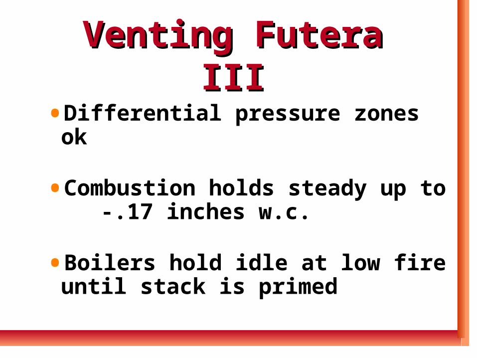
• Differential pressure zones ok
• Combustion holds steady up to -.17 inches w.c.
• Boilers hold idle at low fire until stack is primed
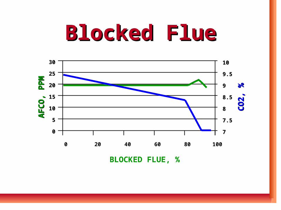
Blocked FlueBlocked Flue
0 20 40 60 80 100
BLOCKED FLUE, %
1010
9.59.5
99
8.58.5
88
7.57.5
77
CO
2, %
CO
2, %
3030
2525
2020
1515
1010
55
00
AF
CO
, PP
MA
FC
O, P
PM
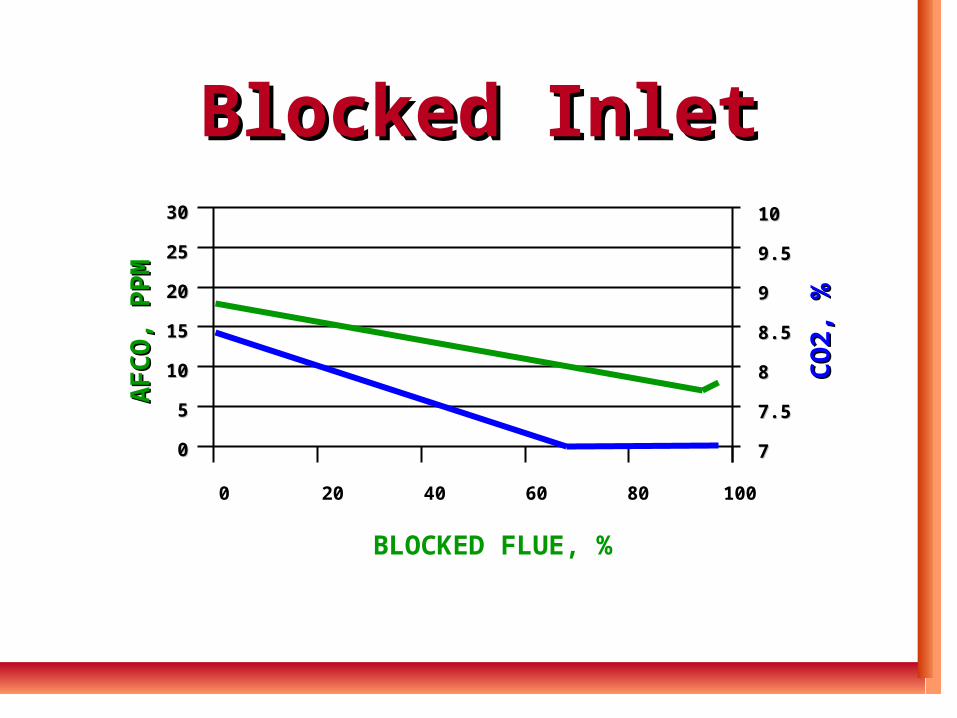
Blocked InletBlocked Inlet3030
2525
2020
1515
1010
55
00
AF
CO
, PP
MA
FC
O, P
PM
0 20 40 60 80 100
BLOCKED FLUE, %
1010
9.59.5
99
8.58.5
88
7.57.5
77
CO
2, %
CO
2, %
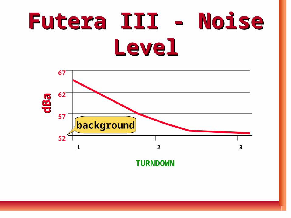
Futera III - Noise LevelFutera III - Noise Level
67
62
57
52
dB
ad
Ba
1 2 3
TURNDOWN
background
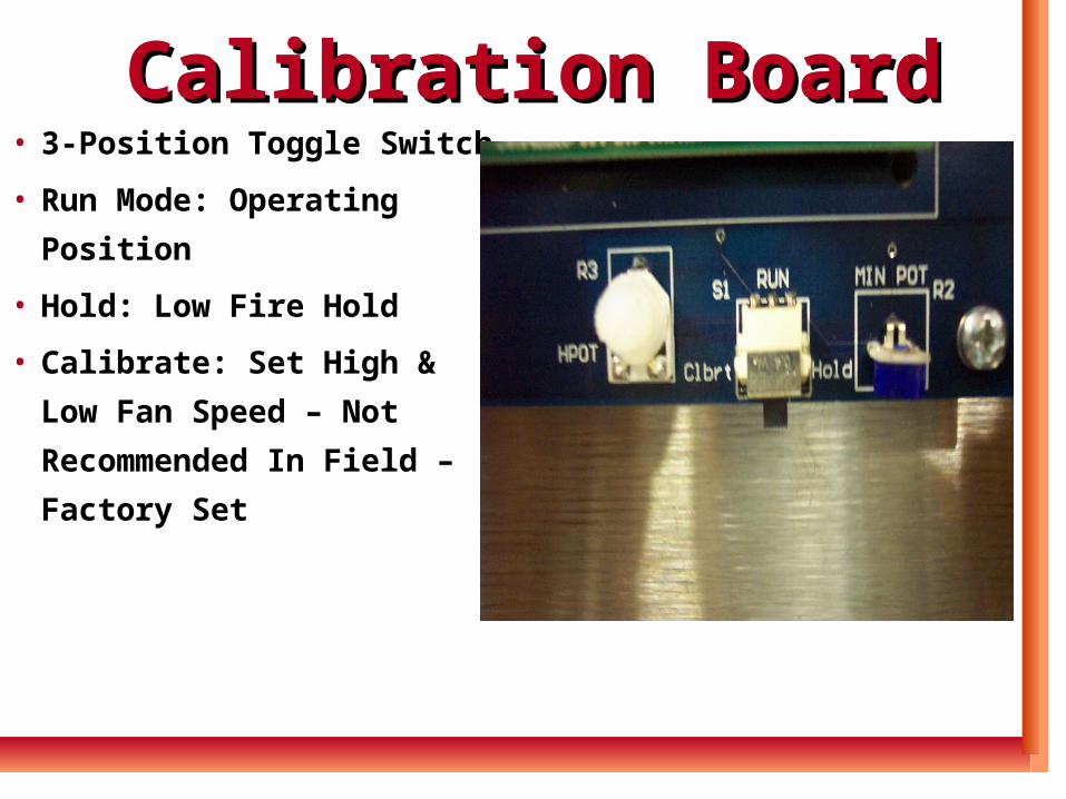
Calibration BoardCalibration Board• 3-Position Toggle Switch
• Run Mode: Operating
Position
• Hold: Low Fire Hold
• Calibrate: Set High & Low
Fan Speed – Not
Recommended In Field –
Factory Set
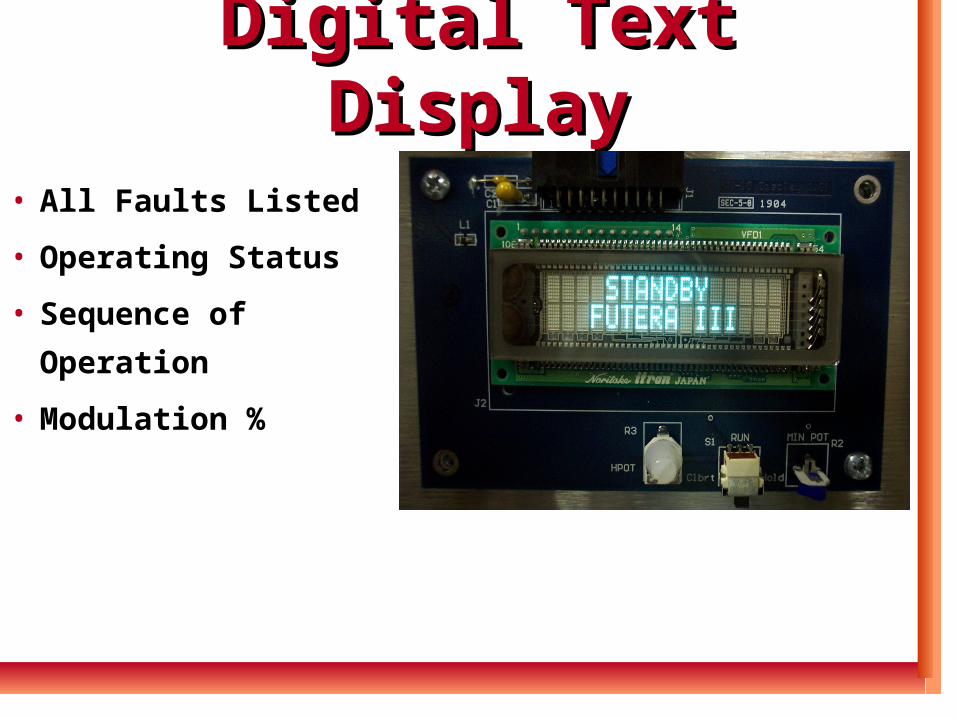
Digital Text DisplayDigital Text Display
• All Faults Listed
• Operating Status
• Sequence of
Operation
• Modulation %
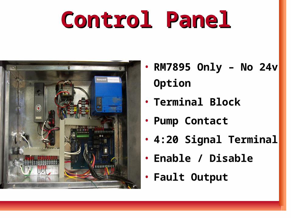
Control PanelControl Panel
• RM7895 Only – No 24v
Option
• Terminal Block
• Pump Contact
• 4:20 Signal Terminal
• Enable / Disable
• Fault Output
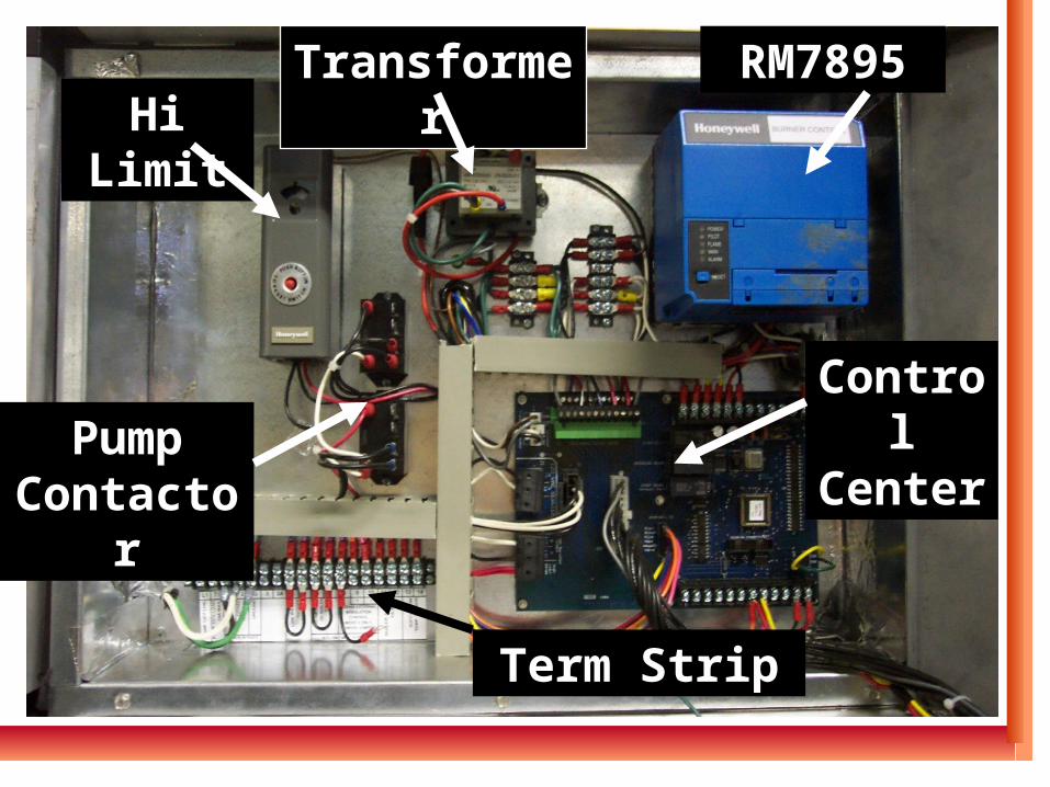
Hi LimitHi LimitTransformerTransformer RM7895RM7895
Control Control CenterCenterPump Pump
ContactorContactor
Term StripTerm Strip
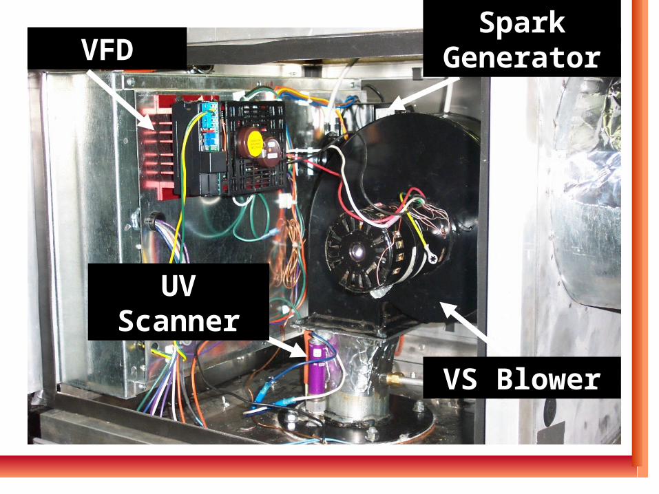
VFDVFD
VS BlowerVS Blower
UV ScannerUV Scanner
Spark Spark GeneratorGenerator
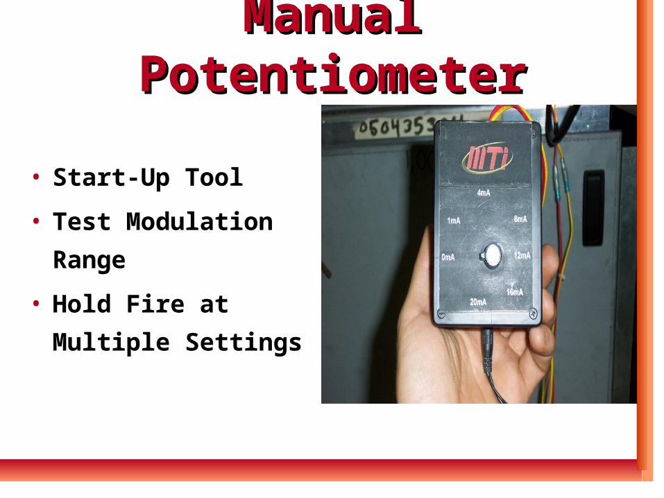
Manual PotentiometerManual Potentiometer
• Start-Up Tool
• Test Modulation
Range
• Hold Fire at Multiple
Settings
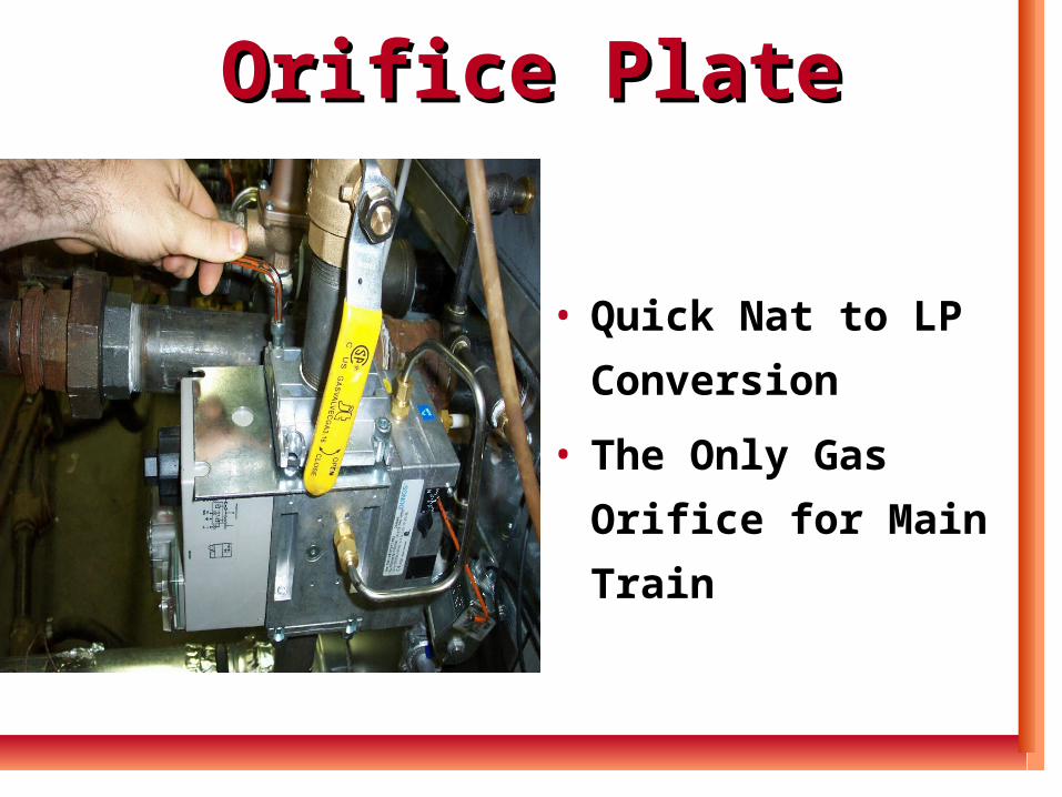
Orifice PlateOrifice Plate
• Quick Nat to LP
Conversion
• The Only Gas Orifice
for Main Train
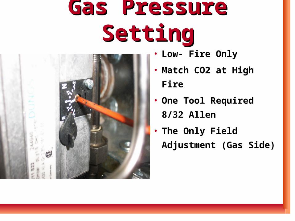
Gas Pressure SettingGas Pressure Setting
• Low- Fire Only
• Match CO2 at High Fire
• One Tool Required 8/32
Allen
• The Only Field
Adjustment (Gas Side)
Thank You For Your Thank You For Your Time !!Time !!