Embed Size (px)
Citation preview
MET 306 Lab 10
11/7/2012 1
Lab 10 Expert Framework Extension
Creo 2.0
Important: Save your work often as Pro/E often spikes the CPU and causes the computer to hang requiring you to use Task Manager to kill the process (at least on my office machine).
Begin Level 7 Learning the Basics of EFX
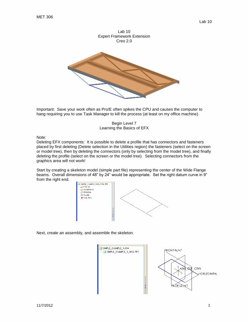
Note: Deleting EFX components: It is possible to delete a profile that has connectors and fasteners placed by first deleting (Delete selection in the Utilities region) the fasteners (select on the screen or model tree), then by deleting the connectors (only by selecting from the model tree), and finally deleting the profile (select on the screen or the model tree). Selecting connectors from the graphics area will not work! Start by creating a skeleton model (simple part file) representing the center of the Wide Flange beams. Overall dimensions of 48” by 24” would be appropriate. Set the right datum curve in 9” from the right end.
Next, create an assembly, and assemble the skeleton.
MET 306 Lab 10
11/7/2012 2
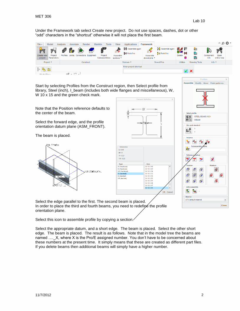
Under the Framework tab select Create new project. Do not use spaces, dashes, dot or other “odd” characters in the “shortcut” otherwise it will not place the first beam.
Start by selecting Profiles from the Construct region, then Select profile from library, Steel (inch), I_beam (includes both wide flanges and miscellaneous), W, W 10 x 15 and the green check mark. Note that the Position reference defaults to the center of the beam. Select the forward edge, and the profile orientation datum plane (ASM_FRONT). The beam is placed.
Select the edge parallel to the first. The second beam is placed. In order to place the third and fourth beams, you need to redefine the profile orientation plane. Select this icon to assemble profile by copying a section. Select the appropriate datum, and a short edge. The beam is placed. Select the other short edge. The beam is placed. The result is as follows. Note that in the model tree the beams are named …._X, where X is the Pro/E assigned number. You don’t have to be concerned about these numbers at the present time. It simply means that these are created as different part files. If you delete beams then additional beams will simply have a higher number.
MET 306 Lab 10
11/7/2012 3
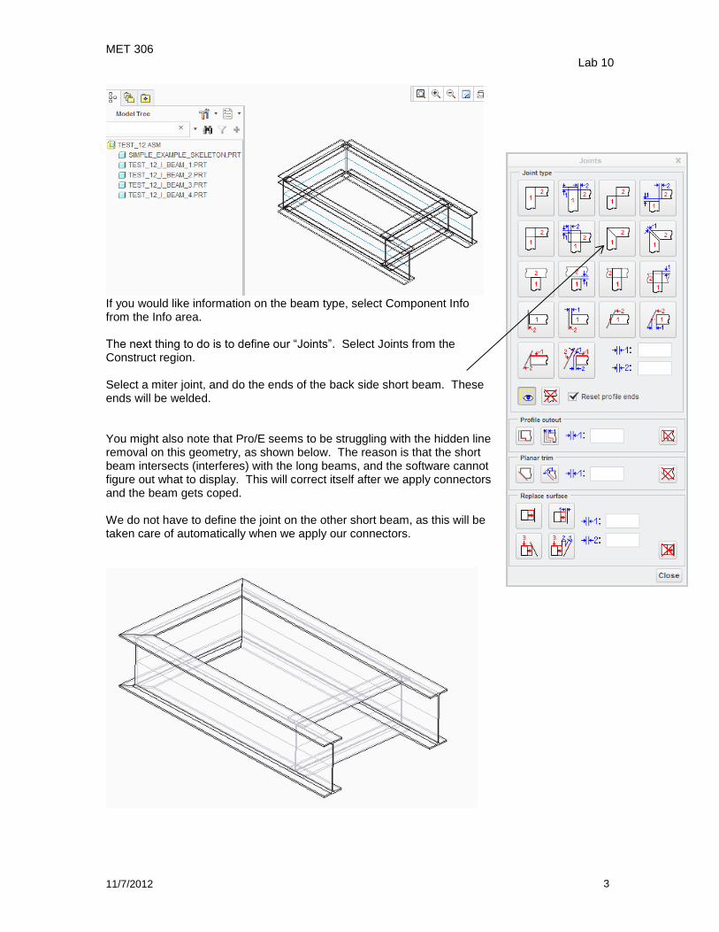
If you would like information on the beam type, select Component Info from the Info area. The next thing to do is to define our “Joints”. Select Joints from the Construct region. Select a miter joint, and do the ends of the back side short beam. These ends will be welded. You might also note that Pro/E seems to be struggling with the hidden line removal on this geometry, as shown below. The reason is that the short beam intersects (interferes) with the long beams, and the software cannot figure out what to display. This will correct itself after we apply connectors and the beam gets coped. We do not have to define the joint on the other short beam, as this will be taken care of automatically when we apply our connectors.
MET 306 Lab 10
11/7/2012 4
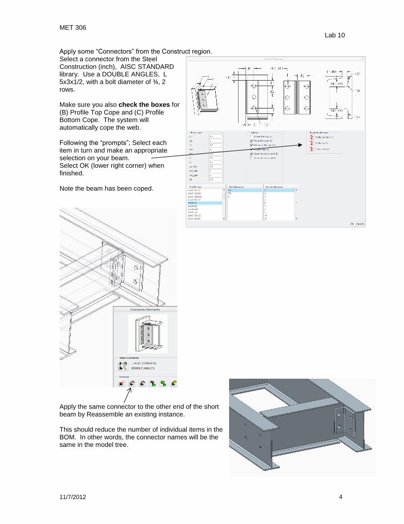
Apply some “Connectors” from the Construct region. Select a connector from the Steel Construction (inch), AISC STANDARD library. Use a DOUBLE ANGLES, L 5x3x1/2, with a bolt diameter of ¾, 2 rows. Make sure you also check the boxes for (B) Profile Top Cope and (C) Profile Bottom Cope. The system will automatically cope the web. Following the “prompts”; Select each item in turn and make an appropriate selection on your beam. Select OK (lower right corner) when finished. Note the beam has been coped.
Apply the same connector to the other end of the short beam by Reassemble an existing instance. This should reduce the number of individual items in the BOM. In other words, the connector names will be the same in the model tree.
MET 306 Lab 10
11/7/2012 5
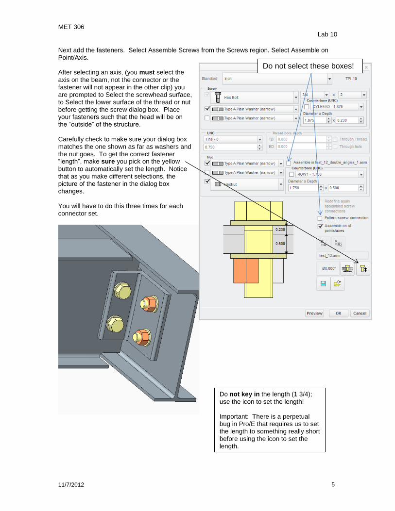
Next add the fasteners. Select Assemble Screws from the Screws region. Select Assemble on Point/Axis. After selecting an axis, (you must select the axis on the beam, not the connector or the fastener will not appear in the other clip) you are prompted to Select the screwhead surface, to Select the lower surface of the thread or nut before getting the screw dialog box. Place your fasteners such that the head will be on the “outside” of the structure. Carefully check to make sure your dialog box matches the one shown as far as washers and the nut goes. To get the correct fastener “length”, make sure you pick on the yellow button to automatically set the length. Notice that as you make different selections, the picture of the fastener in the dialog box changes. You will have to do this three times for each connector set.
Do not key in the length (1 3/4); use the icon to set the length! Important: There is a perpetual bug in Pro/E that requires us to set the length to something really short before using the icon to set the length.
Do not select these boxes!
MET 306 Lab 10
11/7/2012 6
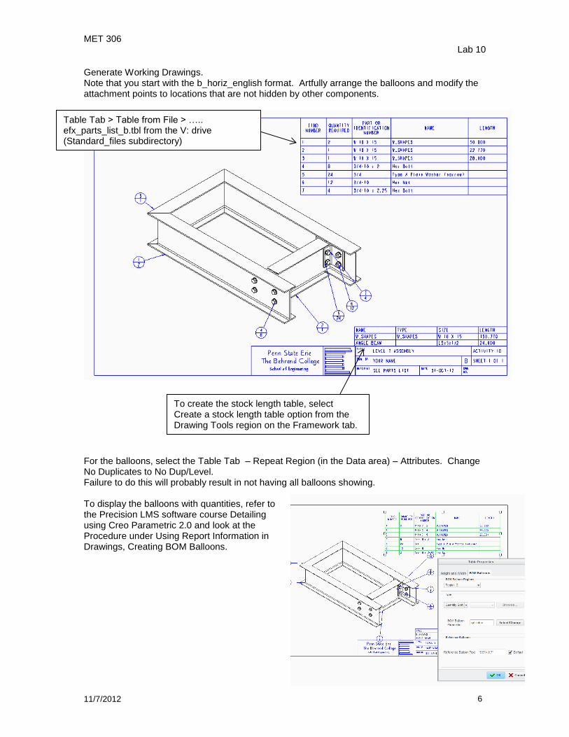
Generate Working Drawings. Note that you start with the b_horiz_english format. Artfully arrange the balloons and modify the attachment points to locations that are not hidden by other components.
For the balloons, select the Table Tab – Repeat Region (in the Data area) – Attributes. Change No Duplicates to No Dup/Level. Failure to do this will probably result in not having all balloons showing. To display the balloons with quantities, refer to the Precision LMS software course Detailing using Creo Parametric 2.0 and look at the Procedure under Using Report Information in Drawings, Creating BOM Balloons.
To create the stock length table, select Create a stock length table option from the Drawing Tools region on the Framework tab.
Table Tab > Table from File > ….. efx_parts_list_b.tbl from the V: drive (Standard_files subdirectory)
MET 306 Lab 10
11/7/2012 7
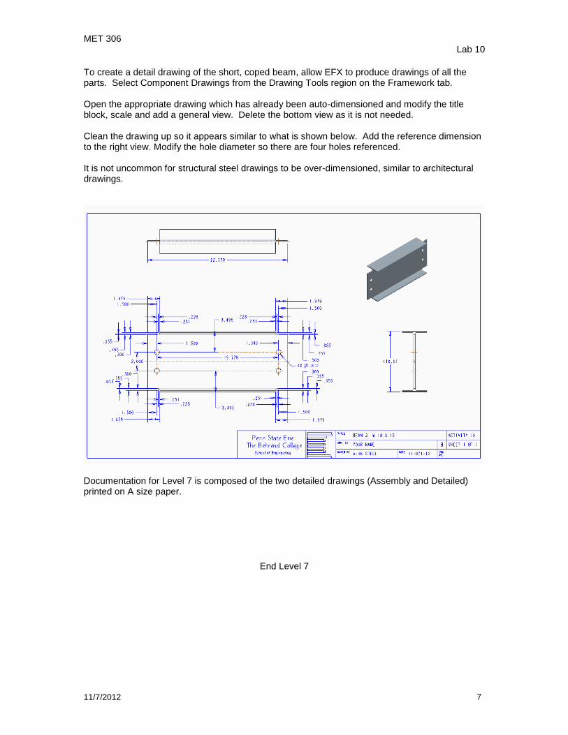
To create a detail drawing of the short, coped beam, allow EFX to produce drawings of all the parts. Select Component Drawings from the Drawing Tools region on the Framework tab. Open the appropriate drawing which has already been auto-dimensioned and modify the title block, scale and add a general view. Delete the bottom view as it is not needed. Clean the drawing up so it appears similar to what is shown below. Add the reference dimension to the right view. Modify the hole diameter so there are four holes referenced. It is not uncommon for structural steel drawings to be over-dimensioned, similar to architectural drawings.
Documentation for Level 7 is composed of the two detailed drawings (Assembly and Detailed) printed on A size paper.
End Level 7

MET 306 Lab 10
11/7/2012 8
Level 8.5 Build the following skeleton part using the dimensions shown.
Assume a 9k loading at the center (4.5k/truss). Use your spreadsheet to define the sizes (minimum based on weight) of the structure. For the long center beam, use a W6x20. Use EFX to build the structure. Hints (these are really important): 1) The bottom centers of the C channels are aligned with the skeleton.
2) The 96” long C channels are the same size as the top chord of the truss.
3) The neutral axis of the angles is aligned with the skeleton.
4) When assembling the profiles, always select New and not Reassemble existing profile
instance.
5) The top of the W6x20 is aligned with the top of the C channels (the depth of the WF is 6.2”). This can be moved under the Profiles – Move Tab.
6) When using the Profiles – Move tab; Select the Rotate Profile (+90, -90 etc), then Select the profile you wish to rotate, then select OK from the Select Dialog box.
7) Notice the orientation of the L members. The open side of the angle faces “out” and the flat side is always “up” so that water does not pond on the steel.
7) Use 3-1/2 x 3-1/2 x ½ angle clips. The L clips for the WF will need to have their “L2” value changed to 2” or they will be too long and run into the flanges of the wide flange.. You can place the “default” size and then replace it with a modified version using “Modify connector element”.
8” overhang, each end
MET 306 Lab 10
11/7/2012 9
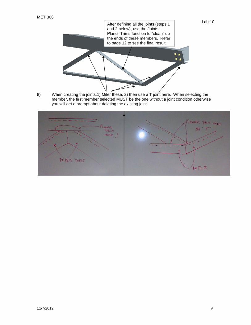
8) When creating the joints,1) Miter these, 2) then use a T joint here. When selecting the
member, the first member selected MUST be the one without a joint condition otherwise you will get a prompt about deleting the existing joint.
After defining all the joints (steps 1 and 2 below), use the Joints – Planer Trims function to “clean” up the ends of these members. Refer to page 12 to see the final result.
MET 306 Lab 10
11/7/2012 10
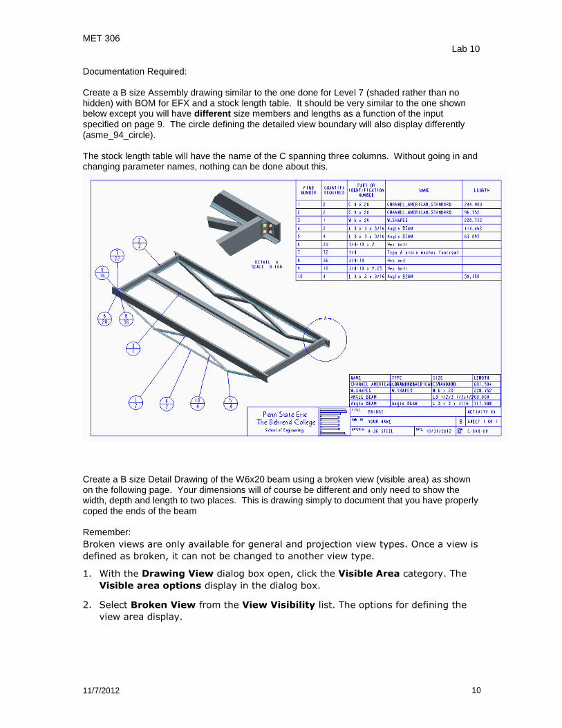
Documentation Required: Create a B size Assembly drawing similar to the one done for Level 7 (shaded rather than no hidden) with BOM for EFX and a stock length table. It should be very similar to the one shown below except you will have different size members and lengths as a function of the input specified on page 9. The circle defining the detailed view boundary will also display differently (asme_94_circle). The stock length table will have the name of the C spanning three columns. Without going in and changing parameter names, nothing can be done about this.
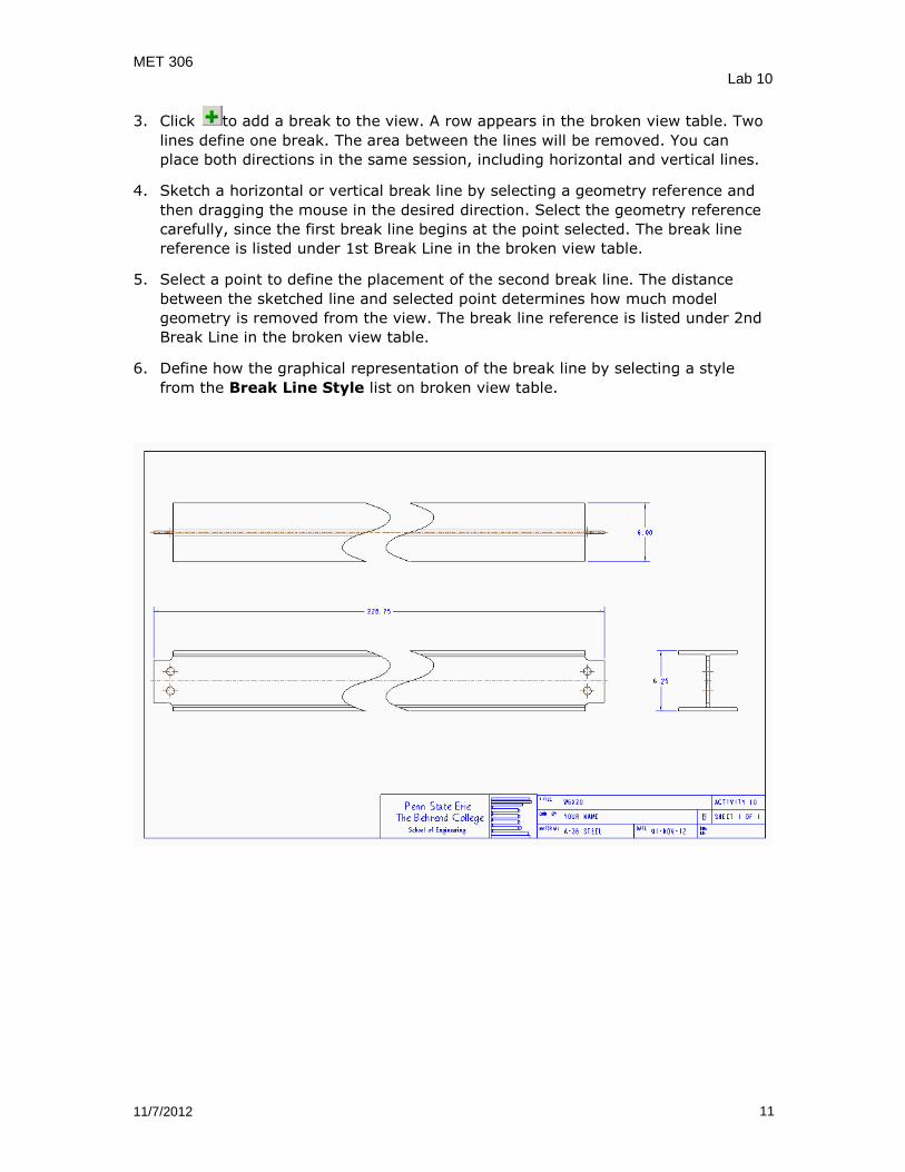
Create a B size Detail Drawing of the W6x20 beam using a broken view (visible area) as shown on the following page. Your dimensions will of course be different and only need to show the width, depth and length to two places. This is drawing simply to document that you have properly coped the ends of the beam Remember:
Broken views are only available for general and projection view types. Once a view is
defined as broken, it can not be changed to another view type.
1. With the Drawing View dialog box open, click the Visible Area category. The
Visible area options display in the dialog box.
2. Select Broken View from the View Visibility list. The options for defining the
view area display.
MET 306 Lab 10
11/7/2012 11
3. Click to add a break to the view. A row appears in the broken view table. Two
lines define one break. The area between the lines will be removed. You can
place both directions in the same session, including horizontal and vertical lines.
4. Sketch a horizontal or vertical break line by selecting a geometry reference and
then dragging the mouse in the desired direction. Select the geometry reference
carefully, since the first break line begins at the point selected. The break line
reference is listed under 1st Break Line in the broken view table.
5. Select a point to define the placement of the second break line. The distance
between the sketched line and selected point determines how much model
geometry is removed from the view. The break line reference is listed under 2nd
Break Line in the broken view table.
6. Define how the graphical representation of the break line by selecting a style
from the Break Line Style list on broken view table.
MET 306 Lab 10
11/7/2012 12
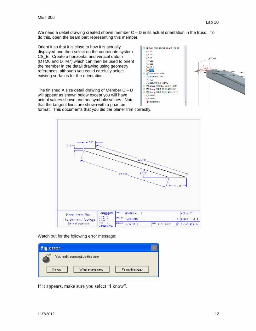
We need a detail drawing created shown member C – D in its actual orientation in the truss. To do this, open the beam part representing this member. Orient it so that it is close to how it is actually displayed and then select on the coordinate system CS_E. Create a horizontal and vertical datum (DTM6 and DTM7) which can then be used to orient the member in the detail drawing using geometry references, although you could carefully select existing surfaces for the orientation. The finished A size detail drawing of Member C – D will appear as shown below except you will have actual values shown and not symbolic values. Note that the tangent lines are shown with a phantom format. This documents that you did the planer trim correctly.
Watch out for the following error message:
If it appears, make sure you select “I know”.
MET 306 Lab 10
11/7/2012 13
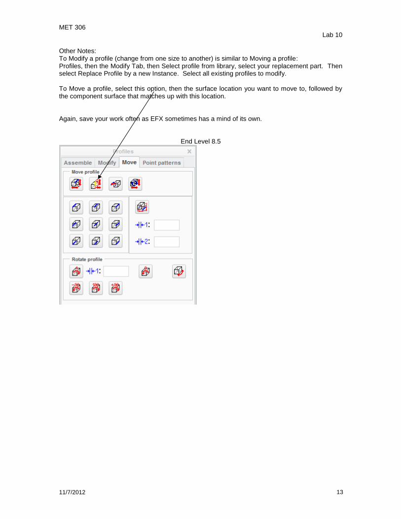
Other Notes: To Modify a profile (change from one size to another) is similar to Moving a profile: Profiles, then the Modify Tab, then Select profile from library, select your replacement part. Then select Replace Profile by a new Instance. Select all existing profiles to modify. To Move a profile, select this option, then the surface location you want to move to, followed by the component surface that matches up with this location. Again, save your work often as EFX sometimes has a mind of its own.
End Level 8.5
MET 306 Lab 10
11/7/2012 14
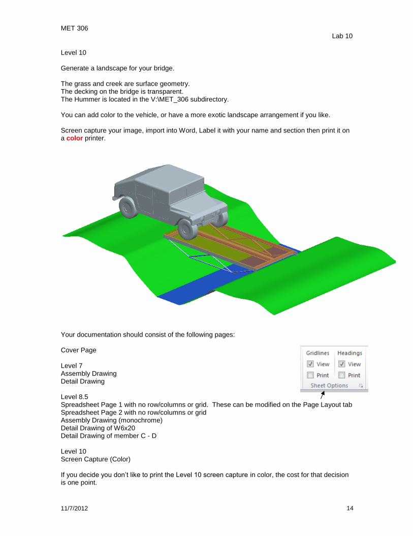
Level 10 Generate a landscape for your bridge. The grass and creek are surface geometry. The decking on the bridge is transparent. The Hummer is located in the V:\MET_306 subdirectory. You can add color to the vehicle, or have a more exotic landscape arrangement if you like. Screen capture your image, import into Word, Label it with your name and section then print it on a color printer.
Your documentation should consist of the following pages: Cover Page Level 7 Assembly Drawing Detail Drawing Level 8.5 Spreadsheet Page 1 with no row/columns or grid. These can be modified on the Page Layout tab Spreadsheet Page 2 with no row/columns or grid Assembly Drawing (monochrome) Detail Drawing of W6x20 Detail Drawing of member C - D Level 10 Screen Capture (Color) If you decide you don’t like to print the Level 10 screen capture in color, the cost for that decision is one point.