Embed Size (px)
Citation preview
Metal Additive Manufacturing: A ReviewWilliam E. Frazier
(Submitted February 24, 2014; published online April 8, 2014)
This paper reviews the state-of-the-art of an important, rapidly emerging, manufacturing technology that isalternatively called additive manufacturing (AM), direct digital manufacturing, free form fabrication, or3D printing, etc. A broad contextual overview of metallic AM is provided. AM has the potential to revo-lutionize the global parts manufacturing and logistics landscape. It enables distributed manufacturing andthe productions of parts-on-demand while offering the potential to reduce cost, energy consumption, andcarbon footprint. This paper explores the material science, processes, and business consideration associatedwith achieving these performance gains. It is concluded that a paradigm shift is required in order to fullyexploit AM potential.
Keywords fabricated metal, modeling processes, powder metal-lurgy
1. Introduction
ASTM has defined additive manufacturing (AM) as ‘‘aprocess of joining materials to make objects from 3D modeldata, usually layer upon layer, as opposed to subtractivemanufacturing methodologies. Synonyms: additive fabrication,additive processes, additive techniques, additive layer manu-facturing, layer manufacturing, and freeform fabrication’’(Ref 1). This definition is broadly applicable to all classes ofmaterials including metals, ceramics, polymers, composites,and biological systems. While AM has been around as a meansof processing materials for, arguably, over two decades, it hasonly recently begun to emerge as an important commercialmanufacturing technology.
In 2009, Bourell et al. (Ref 2) published a roadmap for AMbased on a workshop of 65 key people in AM. Their reportexplored important facets of the AM including:
• Design• Process modeling and control• Materials, processes, and machines• Biomedical applications• Energy and sustainability applications
In 2010, Frazier (Ref 3) published the results of a Navyworkshop entitled ‘‘direct digital manufacturing (DDM) ofmetallic components: affordable, durable, and structurallyefficient aircraft.’’ A vision of parts on demand when andwhere they are needed was articulated. Achieving the visionstate would enhance operational readiness, reduce energyconsumption, and reduce the total ownership cost of navalaircraft through the use of AM. Specific technical challenges
were identified to address the quantitative objectives in theareas of (i) innovative structural design, (ii) qualification andcertification, (iii) maintenance and repair, and (iv) DDMscience and technology. Top level findings include
• High priority should be given to developing integratedin-process, sensing, monitoring, and controls. Machine-to-machine variability must be understood and controlled.
William E. Frazier, Naval Air Systems Command, Patuxent River,MD. Contact e-mail: [email protected].
Nomenclature
3D Three dimensional
AM Additive manufacturing
BCA Business case analysis
BREW Business resource efficiency and waste
CO2PE! Cooperative effort on process emissions in
manufacturing
DDM Direct digital manufacturing
DFE Design for environment
DMLS Direct metal laser sintering
DoD Department of defense
EBPB Electron beam powder bed
EBFFF Electron beam free form fabrication
EIA Environmental impact assessment
EISS Environmental impact scoring systems
FFF Free form fabrication
HIP Hot isotactic pressing
IDA Institute for defense analysis
LAM Laser additive manufacturing
LBPB Laser beam powder bed
LCA Life-cycle analysis
LENS Laser engineered net shaping
NIST National institute for standards and technology
PTAS FFF Plasma transferred arc selected free form fabrication
SBIR Small business innovative research
SLM Selective laser melting
SLS Selective laser sintering
SMD Shaped metal deposition
WAAM Wire and arc additive manufacturing
WFLB Wire fed laser beam
JMEPEG (2014) 23:1917–1928 �ASM InternationalDOI: 10.1007/s11665-014-0958-z 1059-9495/$19.00
Journal of Materials Engineering and Performance Volume 23(6) June 2014—1917
• Alternatives to conventional qualification methods mustbe found; these are likely based upon validated models,probabilistic methods, and part similarities. Part-by-partcertification is costly, time consuming, and antithetical toachieving the Navy�s vision of producing and using AMparts on demand.
• Priority should be given to the development of integratedstructural and materials design tools. This is needed toaccelerate the adoption of AM by the aircraft design com-munity and to promote new innovative structural designsneeded to save energy and weight.
• Underline science of DDM needs to be developed. Phys-ics-based models are needed relating microstructure, prop-erties, and performance. New alloys must be developed tooptimize properties. An understanding of how to controlfatigue properties and reduce surface roughness, must bedeveloped.
Hederick (Ref 4) published a review of AM of metals in 2011.Presented is a nice summary of the various AM technologiesand the dominate AM equipment manufacturers. AM equip-ment was broadly divided into powder bed systems, laserpowder injection systems, and free form fabrication (FFF)systems. Some of the major findings of the report include:
• Materials processed using AM experience complex ther-mal processing cycles. There is a need to better under-stand the link between microstructure, processing, andproperties for AM fabricated parts, as well as developingan AM materials database. He reports that there has beena lot of work on Ti-6Al-4V, but not so much on otheralloys.
• There is a need reduce the variance in properties and qual-ity from machine-to-machine across materials and machinetypes. Therefore, closed-loop feedback control and sensingsystems with intelligent feed forward capability needs tobe developed. Further, the ruggedization of AM equip-ment is needed.
• AM can be applied to the manufacturing of parts that can-not be made with standard machining practices. This pos-sibility enables novel design methodologies.
NIST held a workshop in December of 2012 and recentlypublished the results ‘‘Measurement Science Roadmap forMetal-Based Additive Manufacturing’’ (Ref 5). Importanttechnology challenges were identified in the areas (i) AMmaterials, (ii) AM process and equipment, (iii) AM qualifica-tion and certification, and (iv) AM modeling and simulation.The technology development opportunities identified include:
• Robust in situ process monitoring techniques includingsensors for measuring and monitoring AM processes andproducts.
• A metals design allowable and performance capabilitydatabase
• A shared 3rd party database• An expert system for AM design• Validated physics and properties-based models.
Common to the aforementioned work is the recognition thatAM is a transformative technology. AM will impact componentdesign, cost, and product delivery; it will affect global business
models and logistics; it should enable increased energyefficiency and lower environmental impact.
Standardization of AM processes is an important step in theadvancement of metals AM and is currently on-going. In 2009,the American Society for Testing and Materials (ASTM) F42Committee on AM Technologies was created to guide thedevelopment of international standards in AM. ASTM F2924Specification for AM Titanium-6 Aluminum-4 Vanadium withPowder Bed Fusion was approved in 2012. Other importantstandardizations were created that ultimately assist the advance-ment of AM including, ASTM F2792 standardized AMterminology (2009) and ASTM F2915 Specification for AMFile Format (2011). Standardization of the file formats toadditive manufacturing file (AMF) format allows designs to betransferred between different hardware and software systemsand was developed to support full-color multi-material geom-etries with microstructure and material gradients.
The 2009 RapidTech paper by Bourell et al. (Ref 2)identified the need for a National test bed Center with expertsthat would facilitate the leveraging of equipment and humanresources. In August 2012, the National Additive Manufactur-ing Innovation Institute, now called America Makes, wasformed by President Obama as part of the National Network forManufacturing Innovation. Based in Youngstown, Ohio,NAMII serves as a national resource in expertise for AM.NAMII�s mission is to ‘‘accelerate AM technologies to the U.S.manufacturing sector and increase domestic manufacturingcompetitiveness by fostering a highly collaborative infrastruc-ture for the open exchange of AM information and research;facilitating the development, evaluation, and deployment ofefficient and flexible AM technologies; and educating studentsand training workers in AM technologies to create an adaptive,leading workforce.’’[NAMII website] NAMII has recentlyfunded six AM projects, three on metals, and three onpolymers.
2. Metallic Additive Manufacturing Systems
AM system may be classified/categorized in terms of thematerial feed stock, energy source, build volume, etc. Table 1 isa selected list of equipment manufactures and their equipment.In this table, manufacturing systems are divided into threebroad categories (although there are many more): (i) powderbed systems, (ii) powder feed systems, and (iii) wire feedsystems. The energy source (electron beam, laser, arc, etc.) forthese systems is also provided.
2.1 Powder Bed Systems
All the powder bed systems are manufactured by companieslocated outside the United States. In general, the build volumesof these units are less than 0.03 m3. ARCAM, a Swedishcompany, manufactures the only powder bed electron beamsystem, the ARCAM A2.
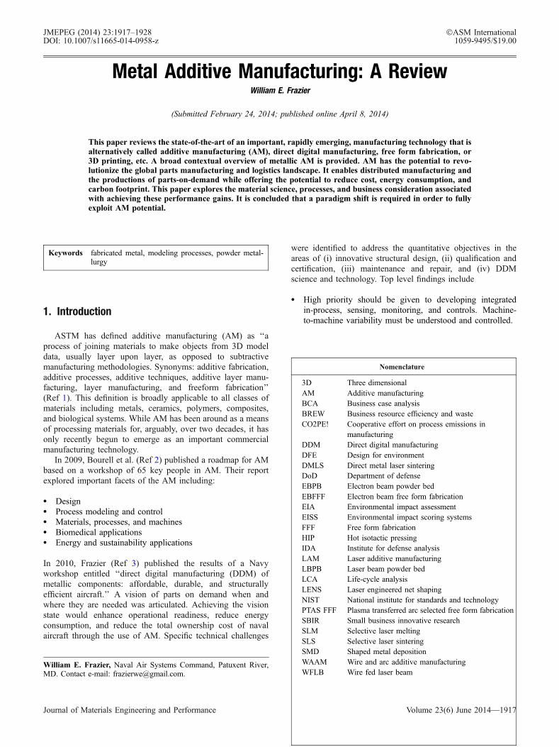
Figure 1 is a schematic of a generic powder bed system. Apowder bed is created by raking powder across the work area.The energy source (electron beam or laser beam) is pro-grammed to deliver energy to the surface of the bed melting orsintering the powder into the desired shape. Additional powderis raked across the work area, and the process is repeated tocreate a solid three dimensional component. The advantages of
1918—Volume 23(6) June 2014 Journal of Materials Engineering and Performance
this system include its ability to produce high resolutionfeatures, internal passages, and maintain dimensional control.
2.2 Powder Feed Systems
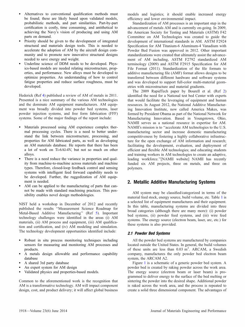
A generic illustration of AM powder feed systems is shownin Fig. 2. The build volumes of these systems are generallylarger (e.g., >1.2 m3 for the Optomec LENS 850-R unit).Further, the powder feed systems lend themselves more readilyto build volume scale up than do the powder bed units. In thesesystems, powders are conveyed through a nozzle onto the buildsurface. A laser is used to melt a monolayer or more of thepowder into the shape desired. This process is repeated to createa solid three dimensional component. There are two dominatetypes of systems in the market. 1. The work piece remainsstationary, and deposition head moves. 2. The deposition headremains stationary, and the work piece is moved. Theadvantages of this type of system include its larger build
volume and its ability to be used to refurbish worn or damagedcomponents.
2.3 Wire Feed Systems
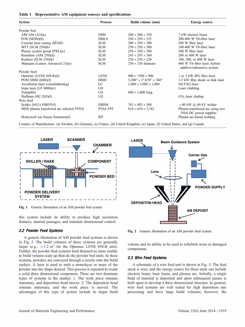
A schematic of a wire feed unit is shown in Fig. 3. The feedstock is wire, and the energy source for these units can includeelectron beam, laser beam, and plasma arc. Initially, a singlebead of material is deposited and upon subsequent passes isbuilt upon to develop a three dimensional structure. In general,wire feed systems are well suited for high deposition rateprocessing and have large build volumes; however, the
Table 1 Representative AM equipment sources and specifications
System Process Build volume (mm) Energy source
Powder bedARCAM (A2)(a) EBM 2009 2009 350 7 kW electron beamEOS (M280)(b) DMLS 2509 2509 325 200-400 W Yb-fiber laserConcept laser cusing (M3)(b) SLM 3009 3509 300 200 W fiber laserMTT (SLM 250)(b) SLM 2509 2509 300 100-400 W Yb-fiber laserPhenix system group (PXL)(c) SLM 2509 2509 300 500 W fiber laserRenishaw (AM 250)(d) SLM 2459 2459 360 200 or 400 W laserRealizer (SLM 250)(b) SLM 2509 2509 220 100, 200, or 400 W laserMatsuura (Lumex Advanced 25)(e) SLM 2509 250 diameter 400 W Yb fiber laser; hybrid
additive/subtractive systemPowder feedOptomec (LENS 850-R)(f) LENS 9009 15009 900 1 or 2 kW IPG fiber laserPOM DMD (66R)(f) DMD 3,200� 9 3�,670� 9 360� 1-5 kW fiber diode or disk laserAccufusion laser consolidation(g) LC 1,0009 1,0009 1,000 Nd:YAG laserIrepa laser (LF 6000)(c) LD Laser claddingTrumpf(b) LD 6009 1,000 longHuffman (HC-205)(f) LD CO2 laser clading
Wire feedSciaky (NG1) EBFFF(f) EBDM 7629 4839 508 >40 kW @ 60 kV welderMER plasma transferred arc selected FFF(f) PTAS FFF 6109 6109 5,182 Plasma transferred arc using two
350A DC power suppliesHoneywell ion fusion formation(f) IFF Plasma arc-based welding
Country of Manufacturer: (a) Sweden, (b) Germany, (c) France, (d) United Kingdom, (e) Japan, (f) United States, and (g) Canada
LASER SCANNER
POWDER BED
COMPONENT
POWDER DELIVERYSYSTEM
ROLLER / RAKE
CHAMBER
Fig. 1 Generic illustration of an AM powder bed system
LASER Beam Guidance System
POWDER SUPPLY
Carrier Gas
Lens
DEPOSITON HEAD
AM DEPOSIT
Fig. 2 Generic illustration of an AM powder feed system
Journal of Materials Engineering and Performance Volume 23(6) June 2014—1919
fabricated product usually requires more extensive machiningthan the powder bed or powder fed systems do.
In summary, there are a large number of diverse AM piecesof equipment commercially available. These may be broadlycharacterized as powder bed, powder fed, and wire fed systems.There are distinct advantages to each type of system dependentupon the intended applications, e.g., repair and refurbishment,small part fabrication, large part fabrication.
3. Technology Challenges
3.1 Process Controls, Sensors and Models
In 2012, the Institute for Defense Analysis (Science andTechnology Policy Institute) reported on status and opportuni-ties of AM (Ref 6). A key finding was that additional R&Dresources need to be applied to technical challenges such asprocess control and modeling. There is a need for real-time,closed-loop process controls and sensor in order to ensurequality, consistency, and reproducibility across AM machines(Ref 3, 6). Since the properties of AM materials are tied to theimmediate past processing history (e.g., build temperature, partgeometry), sensors are being developed to measure melt poolsize and shape as well as melt pool and build temperatures.These concepts are being explored under Navy SBIR projects(Ref 7). These data in combination with predictive algorithmsare needed in order to adjust and control process parameters inreal time to ensure quality, consistency, and reliability.
3.2 Metallurgy
To date, there have been only a limited number of commercialalloys used in AM. Some of these are presented in Table 2. As theAMfieldmatures, it is clear to this author that new alloys will needto be developed in order to exploit the advantages of AM. Ti-6Al-4V has been by far the most extensively investigated. This can beattributed to the strong business case that can be developed forcomplex, low production volume titanium parts.
Electron Beam
EB Gun
Wire Feed
Deposition Layers Substrate
Fig. 3 Generic illustration of an AM wire feed system
Table 2 Selected alloys commercially used in AM processing
Titanium Aluminum Tool steels Super alloys Stainless steel Refractory
Ti-6Al-4V Al-Si-Mg H13 IN625 316 & 316L MoReELI Ti 6061 Cermets IN718 420 Ta-WCP Ti Stellite 347 CoCrc-TiAl PH 17-4 Alumina
2500
2000
1500
1000
500
Tem
per
atu
re, K
1 2 3 4 5 6 7
Time Index
Liquid
β
α + β
Fig. 4 Notional thermal profile of a single layer of Ti-6Al-4Vduring AM
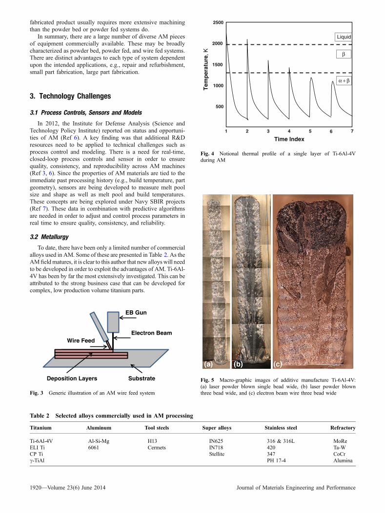
Fig. 5 Macro-graphic images of additive manufacture Ti-6Al-4V:(a) laser powder blown single bead wide, (b) laser powder blownthree bead wide, and (c) electron beam wire three bead wide
1920—Volume 23(6) June 2014 Journal of Materials Engineering and Performance
AM is a layer by layer manufacturing process. A single layerof metal is ‘‘cast’’ upon a previous layer resulting in a complex,time dependent temperature profiles within the part beingfabricated. The result is that the alloy may experience repeatedsolid state and liquid-solid phase transformations. Figure 4 is anotional thermal profile for a single layer AM processedTi-6Al-4V (Ref 8, 9). In this graph, the temperature of a singlelayer is mapped showing that this layer experienced two liquid-solid transformation and two alpha-beta transformations. Theseprofiles are dependent upon a number of variables including theAM equipment, the time between passes, and the size of thepart being fabricated.
In general, AM is a relatively rapid solidification process.Zheng et al. (Ref 10-12) report cooling rates for the LENSprocess to be between 103 and 104 K/s. Vilaro et al. (Ref 10)reported cooling rates of 104 K/s for SLM. Zheng et al. (Ref 12)used dendrite arm spacing to establish the cooling rate of LENSprocessed 316L. Further, the heat flow in AM processes isdirectional frequently resulting in columnar microstructures.Kobryn and Semiatin developed a solidification map forTi-6Al-4V using Nd:YAG laser and a CO2 Laser. Using thismethod, the maps of columnar, mixed, and equiaxed structureswere developed as a function of cooling rate, G(K/s), versussolidification rate, R(cm/s) (Ref 13).
The combined effect of rapid solidification, directionalcooling, and phase transformations induced by repeated thermal
cycles has a profound influence on the microstructures of thematerials deposited. Rapid solidification reduces elementalpartitioning and extends solid solubility and can result inmetastable phase formation. Directional heat extraction mayresult in preferred directionality in grain growth. Repeatedthermal cycles have a possible complex set of effects, includingmicrostructural banding, i.e., microstructural differencesbetween depositions layers (Ref 1, 14-16). For Ti-6Al-4V,Vilaro et al. reported large columnar grains 150-lm wide;re-melting resulted in a strong texture as a result of epitaxialgrowth nucleating on columnar grain sites. A strong anisotropyin fracture behavior was also noted and attributed to manufac-turing defects. Some of the typical defects observed in the SLMprocess were micro-porosity and lack of fusion. The micro-porosity (10-50 lm at less than 1 vol.%) was reported andattributed to gas entrapment (Ref 11) as was the alpha primephase due to rapid cooling.
Macro-graphic images of additive manufacture Ti-6Al-4Vare presented in Fig. 5. Figure 5(a) and (b) is materialsproduced by ARL Penn States laser beam, powder blownsystem. Figure 5(c) is produced by NASA�s electron beam,wire fed system. The typically observed columnar grains areseen growing in the z-direction (i.e., perpendicular to the buildplane) and in the direction of heat extraction. Althoughcolumnar grain growth is observed in materials produced byboth systems, it is less prominent in the single pass laser
Fig. 7 Optical micrographs of electron beam wire produced Ti-6Al-4V in the as-fabricated condition
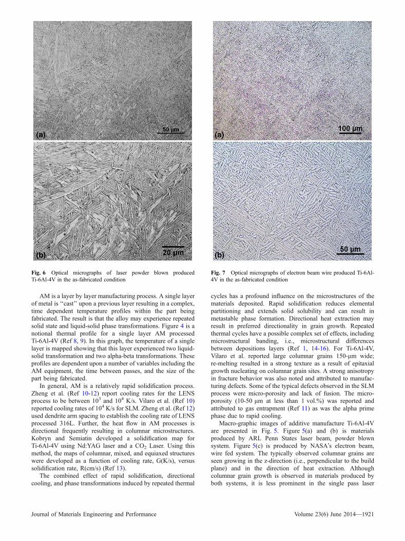
Fig. 6 Optical micrographs of laser powder blown producedTi-6Al-4V in the as-fabricated condition
Journal of Materials Engineering and Performance Volume 23(6) June 2014—1921
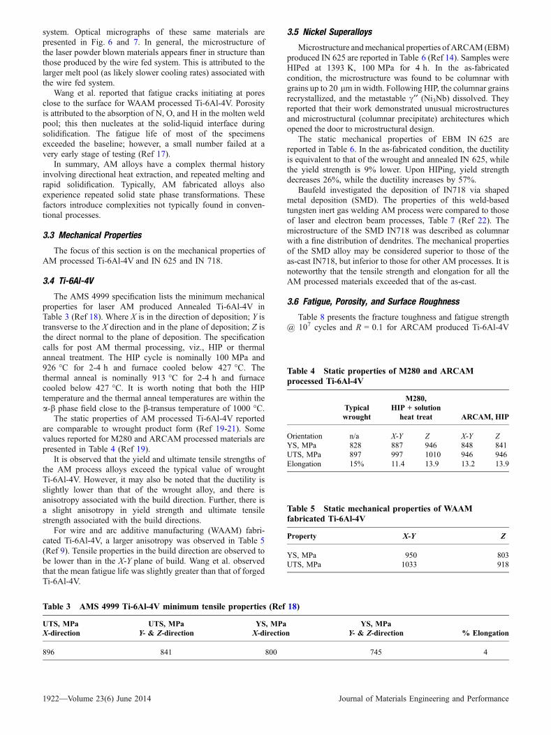
system. Optical micrographs of these same materials arepresented in Fig. 6 and 7. In general, the microstructure ofthe laser powder blown materials appears finer in structure thanthose produced by the wire fed system. This is attributed to thelarger melt pool (as likely slower cooling rates) associated withthe wire fed system.
Wang et al. reported that fatigue cracks initiating at poresclose to the surface for WAAM processed Ti-6Al-4V. Porosityis attributed to the absorption of N, O, and H in the molten weldpool; this then nucleates at the solid-liquid interface duringsolidification. The fatigue life of most of the specimensexceeded the baseline; however, a small number failed at avery early stage of testing (Ref 17).
In summary, AM alloys have a complex thermal historyinvolving directional heat extraction, and repeated melting andrapid solidification. Typically, AM fabricated alloys alsoexperience repeated solid state phase transformations. Thesefactors introduce complexities not typically found in conven-tional processes.
3.3 Mechanical Properties
The focus of this section is on the mechanical properties ofAM processed Ti-6Al-4V and IN 625 and IN 718.
3.4 Ti-6Al-4V
The AMS 4999 specification lists the minimum mechanicalproperties for laser AM produced Annealed Ti-6Al-4V inTable 3 (Ref 18). Where X is in the direction of deposition; Y istransverse to the X direction and in the plane of deposition; Z isthe direct normal to the plane of deposition. The specificationcalls for post AM thermal processing, viz., HIP or thermalanneal treatment. The HIP cycle is nominally 100 MPa and926 �C for 2-4 h and furnace cooled below 427 �C. Thethermal anneal is nominally 913 �C for 2-4 h and furnacecooled below 427 �C. It is worth noting that both the HIPtemperature and the thermal anneal temperatures are within thea-b phase field close to the b-transus temperature of 1000 �C.
The static properties of AM processed Ti-6Al-4V reportedare comparable to wrought product form (Ref 19-21). Somevalues reported for M280 and ARCAM processed materials arepresented in Table 4 (Ref 19).
It is observed that the yield and ultimate tensile strengths ofthe AM process alloys exceed the typical value of wroughtTi-6Al-4V. However, it may also be noted that the ductility isslightly lower than that of the wrought alloy, and there isanisotropy associated with the build direction. Further, there isa slight anisotropy in yield strength and ultimate tensilestrength associated with the build directions.
For wire and arc additive manufacturing (WAAM) fabri-cated Ti-6Al-4V, a larger anisotropy was observed in Table 5(Ref 9). Tensile properties in the build direction are observed tobe lower than in the X-Y plane of build. Wang et al. observedthat the mean fatigue life was slightly greater than that of forgedTi-6Al-4V.
3.5 Nickel Superalloys
Microstructure andmechanical properties ofARCAM (EBM)produced IN 625 are reported in Table 6 (Ref 14). Samples wereHIPed at 1393 K, 100 MPa for 4 h. In the as-fabricatedcondition, the microstructure was found to be columnar withgrains up to 20 lm in width. Following HIP, the columnar grainsrecrystallized, and the metastable c¢¢ (Ni3Nb) dissolved. Theyreported that their work demonstrated unusual microstructuresand microstructural (columnar precipitate) architectures whichopened the door to microstructural design.
The static mechanical properties of EBM IN 625 arereported in Table 6. In the as-fabricated condition, the ductilityis equivalent to that of the wrought and annealed IN 625, whilethe yield strength is 9% lower. Upon HIPing, yield strengthdecreases 26%, while the ductility increases by 57%.
Baufeld investigated the deposition of IN718 via shapedmetal deposition (SMD). The properties of this weld-basedtungsten inert gas welding AM process were compared to thoseof laser and electron beam processes, Table 7 (Ref 22). Themicrostructure of the SMD IN718 was described as columnarwith a fine distribution of dendrites. The mechanical propertiesof the SMD alloy may be considered superior to those of theas-cast IN718, but inferior to those for other AM processes. It isnoteworthy that the tensile strength and elongation for all theAM processed materials exceeded that of the as-cast.
3.6 Fatigue, Porosity, and Surface Roughness
Table 8 presents the fracture toughness and fatigue strength@ 107 cycles and R = 0.1 for ARCAM produced Ti-6Al-4V
Table 3 AMS 4999 Ti-6Al-4V minimum tensile properties (Ref 18)
UTS, MPa UTS, MPa YS, MPa YS, MPa% ElongationX-direction Y- & Z-direction X-direction Y- & Z-direction
896 841 800 745 4
Table 4 Static properties of M280 and ARCAMprocessed Ti-6Al-4V
Typicalwrought
M280,HIP + solution
heat treat ARCAM, HIP
Orientation n/a X-Y Z X-Y ZYS, MPa 828 887 946 848 841UTS, MPa 897 997 1010 946 946Elongation 15% 11.4 13.9 13.2 13.9
Table 5 Static mechanical properties of WAAMfabricated Ti-6Al-4V
Property X-Y Z
YS, MPa 950 803UTS, MPa 1033 918
1922—Volume 23(6) June 2014 Journal of Materials Engineering and Performance
(Ref 20). The porosity in the as-fabricated specimens wasreport to be less than 50 lm in diameter and was attributed toargon gas entrapment. HIP processing eliminated the residualporosity and enhances properties. Fatigue strength of the HIPedalloy in the Z orientation is 24% greater than in theas-fabricated condition. Similarly, the fatigue strength ofthe HIPed alloy in the X-Y orientation is 27% greater than inthe as-fabricated condition. Fatigue strength in the X-Yorientation is nearly 8% greater than in the Z orientation forthe as-fabricated material; in the HIPed condition, the fatiguestrength is 11% greater.
Surface finish also affects fatigue performance (Ref 23). Chanet al. investigated the effect of surface roughness on the fatiguelife of EBM &LBM Ti-6Al-4V using an ARCAM and EOS,respectively. They employed a three point bend test with amaximum surface stress of 600 MPa and a stress ratio, R, of 0.1.They found that the fatigue life of rolled Ti-6Al-4V>LBM>EBM fabricated alloys. They correlated fatigue life to surfacefinish, and from their data, Eq 1 can readily be derived
lnðfatigue lifeÞ ¼ �0:34 lnðSurface RougnessÞ þ Constant
ðEq 1Þ
Very roughly, this means as surface roughness increases from3 to 1000 Ra, the fatigue life decreases from 105 to 104
cycles.Greitemeir et al. (Ref 24) investigated the properties and
microstructure of Ti-6Al-4V produced using electron beampowder bed (EBPB) and laser beam powder bed (LBPB)techniques as well as wire fed laser beam (WFLB). Theyreported that the morphology of the porosity for EBPB andLBPB differed significantly. The LBPB processed materialexhibited irregular-shaped pores whereas the porosity of theEBPB produced alloys was spherical. With regard to high cycle
fatigue life, they concluded that surface defects had the mostpronounced impact on reducing high cycle fatigue life. In termsof fatigue crack growth performance, Greitemeir et al. (Ref 24)concluded that porosity was not the dominant factor rather itwas the alloy�s microstructure. Stated another way, theyconcluded that HIP closure of porosity did not have asignificant impact on fatigue crack growth.
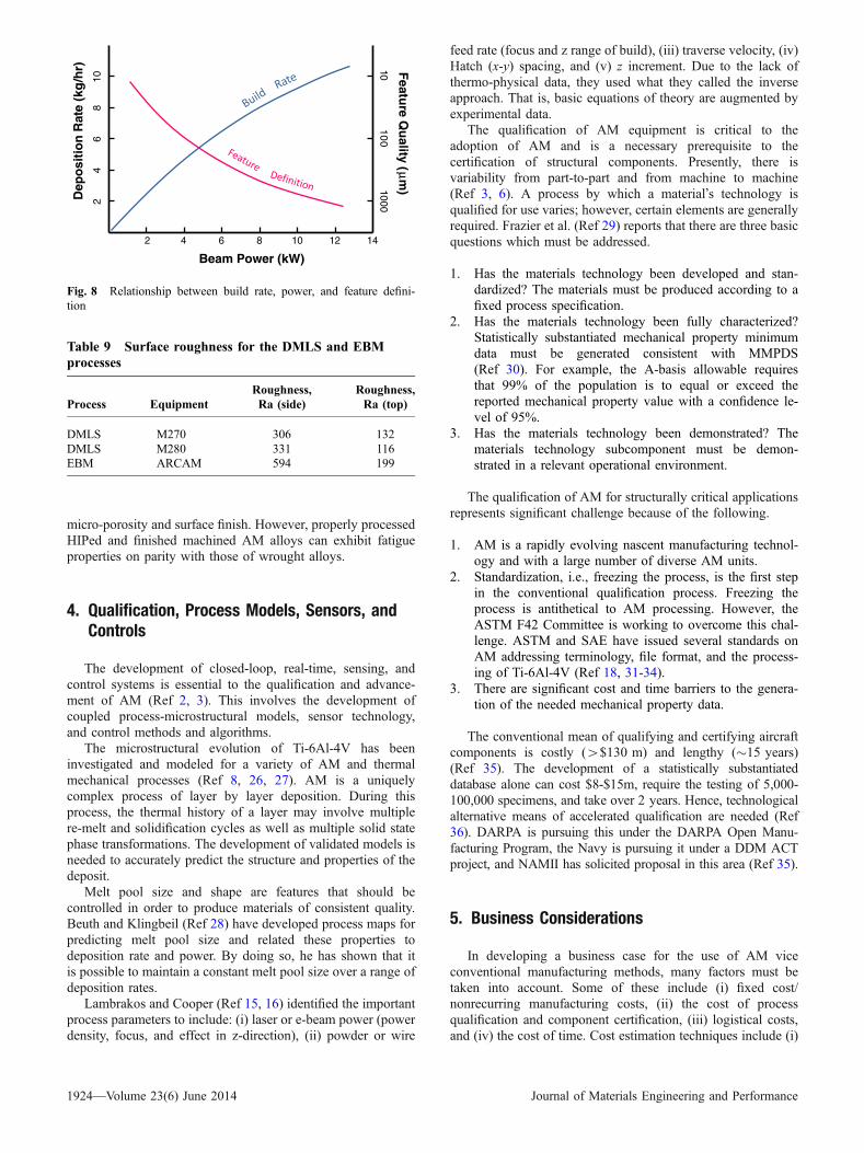
Martukanitz and Simpson (Ref 25) reported that build rateand feature definition are closely linked and related to surfacequality. Figure 8 illustrates the relationship between build rate,power, and feature quality. In general, as build rate increases,feature quality/resolution decreases. The implication is that forfatigue critical parts fabricated using high deposition rate AMprocesses, post process surface finishing may be necessary.
The surface finish is affected by the type of equipment, thedirection of build, and the process parameters used (Ref 19).Table 9 illustrates this impact.
It can be observed that the surface roughness of the build atright angles to the energy source (side) is 2-3 times as rough asthe surfaces parallel to the energy source (top). It may befurther noted that the DMLS systems produce surfacesapproximately twice as smooth as the EBM. Surface conditionis most important for fatigue critical parts intended for use intheir as-fabricated, net shape condition. This is especiallyrelevant for parts with complex internal features where surfacefinishing may be impracticable.
In summary, when properly processed, the static mechanicalproperties of AM metallic materials are comparable to conven-tionally fabricated metallic components. The relatively highcooling rates achieved reduce partitioning and favor reducedgrain sizes. However, AM fabricated materials do exhibitmicrostructural and mechanical property anisotropy with theZ-direction generally being the weakest. Dynamic properties ofAM produced alloys are dominated by defect structures, viz.,
Table 6 Static mechanical properties of AM fabricated IN625 (Ref 14)
Process Yield strength, MPa Tensile strength, MPa % Elongation
Wrought (annealed) 450 890 44As-fabricated EBM 410 750 44EBM + HIP 330 770 69Wrought (cold worked) 1,100 ÆÆÆ 18
Table 7 Mechanical properties of AM fabricated IN718 (Ref 22)
AM Process UTS, MPa YS, MPa % Elongation
SMD 828± 8 473± 6 28± 2As-cast 786 488 11Laser 904 552 16EB 910 580 22
Table 8 Fatigue and fracture toughness properties of ARCAM produced Ti-6Al-4V (Ref 20)
Process Orientation Porosity, % KIC, MPa�m STD, MPa�m Fatigue strength at 107 cycles, MPa
As-fabricated Z 0.19 78.1 2.3 407As-fabricated X-Y 0.11 96.9 0.99 441HIP Z 0.00 83.1 0.09 538HIP X-Y 0.00 99.0 1.1 607
Journal of Materials Engineering and Performance Volume 23(6) June 2014—1923
micro-porosity and surface finish. However, properly processedHIPed and finished machined AM alloys can exhibit fatigueproperties on parity with those of wrought alloys.
4. Qualification, Process Models, Sensors, andControls
The development of closed-loop, real-time, sensing, andcontrol systems is essential to the qualification and advance-ment of AM (Ref 2, 3). This involves the development ofcoupled process-microstructural models, sensor technology,and control methods and algorithms.
The microstructural evolution of Ti-6Al-4V has beeninvestigated and modeled for a variety of AM and thermalmechanical processes (Ref 8, 26, 27). AM is a uniquelycomplex process of layer by layer deposition. During thisprocess, the thermal history of a layer may involve multiplere-melt and solidification cycles as well as multiple solid statephase transformations. The development of validated models isneeded to accurately predict the structure and properties of thedeposit.
Melt pool size and shape are features that should becontrolled in order to produce materials of consistent quality.Beuth and Klingbeil (Ref 28) have developed process maps forpredicting melt pool size and related these properties todeposition rate and power. By doing so, he has shown that itis possible to maintain a constant melt pool size over a range ofdeposition rates.
Lambrakos and Cooper (Ref 15, 16) identified the importantprocess parameters to include: (i) laser or e-beam power (powerdensity, focus, and effect in z-direction), (ii) powder or wire
feed rate (focus and z range of build), (iii) traverse velocity, (iv)Hatch (x-y) spacing, and (v) z increment. Due to the lack ofthermo-physical data, they used what they called the inverseapproach. That is, basic equations of theory are augmented byexperimental data.
The qualification of AM equipment is critical to theadoption of AM and is a necessary prerequisite to thecertification of structural components. Presently, there isvariability from part-to-part and from machine to machine(Ref 3, 6). A process by which a material�s technology isqualified for use varies; however, certain elements are generallyrequired. Frazier et al. (Ref 29) reports that there are three basicquestions which must be addressed.
1. Has the materials technology been developed and stan-dardized? The materials must be produced according to afixed process specification.
2. Has the materials technology been fully characterized?Statistically substantiated mechanical property minimumdata must be generated consistent with MMPDS(Ref 30). For example, the A-basis allowable requiresthat 99% of the population is to equal or exceed thereported mechanical property value with a confidence le-vel of 95%.
3. Has the materials technology been demonstrated? Thematerials technology subcomponent must be demon-strated in a relevant operational environment.
The qualification of AM for structurally critical applicationsrepresents significant challenge because of the following.
1. AM is a rapidly evolving nascent manufacturing technol-ogy and with a large number of diverse AM units.
2. Standardization, i.e., freezing the process, is the first stepin the conventional qualification process. Freezing theprocess is antithetical to AM processing. However, theASTM F42 Committee is working to overcome this chal-lenge. ASTM and SAE have issued several standards onAM addressing terminology, file format, and the process-ing of Ti-6Al-4V (Ref 18, 31-34).
3. There are significant cost and time barriers to the genera-tion of the needed mechanical property data.
The conventional mean of qualifying and certifying aircraftcomponents is costly (>$130 m) and lengthy (�15 years)(Ref 35). The development of a statistically substantiateddatabase alone can cost $8-$15m, require the testing of 5,000-100,000 specimens, and take over 2 years. Hence, technologicalalternative means of accelerated qualification are needed (Ref36). DARPA is pursuing this under the DARPA Open Manu-facturing Program, the Navy is pursuing it under a DDM ACTproject, and NAMII has solicited proposal in this area (Ref 35).
5. Business Considerations
In developing a business case for the use of AM viceconventional manufacturing methods, many factors must betaken into account. Some of these include (i) fixed cost/nonrecurring manufacturing costs, (ii) the cost of processqualification and component certification, (iii) logistical costs,and (iv) the cost of time. Cost estimation techniques include (i)
Beam Power (kW)
Dep
osi
tio
n R
ate
(kg
/hr) F
eature Q
uality (μ
m)
2 4 6 8 10 12 14
24
68
10
1010
01000
Fig. 8 Relationship between build rate, power, and feature defini-tion
Table 9 Surface roughness for the DMLS and EBMprocesses
Process EquipmentRoughness,Ra (side)
Roughness,Ra (top)
DMLS M270 306 132DMLS M280 331 116EBM ARCAM 594 199
1924—Volume 23(6) June 2014 Journal of Materials Engineering and Performance
analogy based, (ii) parametric, and (iii) engineering (Ref 37).Further, the method of allocating cost is also relevant andincludes (i) activity-based costing, (ii) total life cycle costs, (iii)target costs, and (iv) full costing (Ref 37-40).
The UK Technology Strategy Board reported on shaping thenational (UK) competency for AM. In 2011, AM sales werevalued at $1.9B with a sustained double digit growth. Basedupon projections, sales are expected to grow at a rate of $7.5B/year by 2020; however, if the barriers to AM are addressed,sales could exceed $100B/year (Ref 41). The principle barriersto full realization of this target were identified as cost, quality,range of materials, and size limitations. Among the areas thatwere identified as needing work were (i) increase in depositionrate by 4-109, lower material costs, in-process, closed-loopcontrol systems to reduce process variance, training fordesigners of AM, industry standards for AM qualification,and materials optimized for AM.
Gnam et al. (Ref 42) examined LENS repair of IN 625 3rdstage turbine blades at the Anniston Army Depot. They foundsavings of $6,297/part or $1,444,416/year. For an AV8B Ti-6Al-4V engine blade tip repair, Kelly (Ref 43) calculated an81% cost saving at a value of $715 k/year. Phinazee (Ref 44)describes the benefits of using the Sciaky EBFFF process tofabricate a typical Ti-6Al-4V airframe component. The AMprocess was found to have 79% greater material utilizationefficiency, and the fabrication cost was reduced from $17, 430to $9,810. Kinsella investigated the deposition of IN718 alloyfeatures on a forged engine case. A 30% cost savings wererealized using electron beam wire deposition as compared toconventional fabrication methods (Ref 45). Lockheed Martin(LM) is pursing the application of AM Ti-6Al-4V on the JSF(Ref 46). Considerable potential cost saving was identified forparts such as the F-35 CTOL/STOVL Flaperon Spar. Brice,Needler, and Rosenberger quote a LM VP for global integra-tion, ‘‘This new process offers the potential to save between 30and 50% of the cost of machining aerospace titanium structuralcomponents, which are some of the most expensive compo-nents in the F-35 airframe.’’
Wide spread acceptance of AM necessarily implies thatmanufactures can be profitable. Factors favoring AM are listedin Table 10.
The cost associated with manufacturing can be divided intocosts which are fixed and those which are recurring. Fixed costsinclude such things as tools, dies, buildings, etc. These costsmust be amortized over the number of items produced.Recurring costs are cost such as materials, labor, etc. Thesecosts are more directly associated with a part being produced.
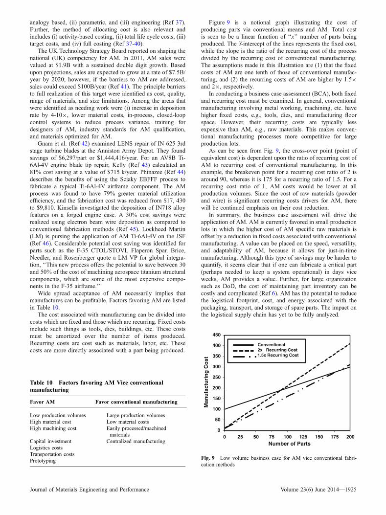
Figure 9 is a notional graph illustrating the cost ofproducing parts via conventional means and AM. Total costis seen to be a linear function of ‘‘x’’ number of parts beingproduced. The Y-intercept of the lines represents the fixed cost,while the slope is the ratio of the recurring cost of the processdivided by the recurring cost of conventional manufacturing.The assumptions made in this illustration are (1) that the fixedcosts of AM are one tenth of those of conventional manufac-turing, and (2) the recurring costs of AM are higher by 1.59and 29, respectively.
In conducting a business case assessment (BCA), both fixedand recurring cost must be examined. In general, conventionalmanufacturing involving metal working, machining, etc. havehigher fixed costs, e.g., tools, dies, and manufacturing floorspace. However, their recurring costs are typically lessexpensive than AM, e.g., raw materials. This makes conven-tional manufacturing processes more competitive for largeproduction lots.
As can be seen from Fig. 9, the cross-over point (point ofequivalent cost) is dependent upon the ratio of recurring cost ofAM to recurring cost of conventional manufacturing. In thisexample, the breakeven point for a recurring cost ratio of 2 isaround 90, whereas it is 175 for a recurring ratio of 1.5. For arecurring cost ratio of 1, AM costs would be lower at allproduction volumes. Since the cost of raw materials (powderand wire) is significant recurring costs drivers for AM, therewill be continued emphasis on their cost reduction.
In summary, the business case assessment will drive theapplication of AM. AM is currently favored in small productionlots in which the higher cost of AM specific raw materials isoffset by a reduction in fixed costs associated with conventionalmanufacturing. A value can be placed on the speed, versatility,and adaptability of AM, because it allows for just-in-timemanufacturing. Although this type of savings may be harder toquantify, it seems clear that if one can fabricate a critical part(perhaps needed to keep a system operational) in days viceweeks, AM provides a value. Further, for large organizationsuch as DoD, the cost of maintaining part inventory can becostly and complicated (Ref 6). AM has the potential to reducethe logistical footprint, cost, and energy associated with thepackaging, transport, and storage of spare parts. The impact onthe logistical supply chain has yet to be fully analyzed.
Table 10 Factors favoring AM Vice conventionalmanufacturing
Favor AM Favor conventional manufacturing
Low production volumes Large production volumesHigh material cost Low material costsHigh machining cost Easily processed/machined
materialsCapital investment Centralized manufacturingLogistics costsTransportation costsPrototyping
0
50
100
150
200
250
300
350
400
450
0 25 50 75 100 125 150 175 200
Man
ufa
ctu
rin
g C
ost
Number of Parts
Conventional2x Recurring Cost1.5x Recurring Cost
Fig. 9 Low volume business case for AM vice conventional fabri-cation methods
Journal of Materials Engineering and Performance Volume 23(6) June 2014—1925
6. Environment, Energy Consumption and CarbonFootprint
Drizo and Pegna (Ref 47) reviewed the state-of-the-artenvironmental impact assessment (EIA) of rapid prototyping. Avariety of methods were examined to measure environmentalimpact including life-cycle analysis (LCA), environmentalimpact scoring systems (EISS), and design for environment(DFE). They found that the scarcity of research and the rapidevolution of this technology left a large number of unresolvedissues (Ref 47). The authors recommend a joint effort ofprocess control engineers, designers, and environmental spe-cialist to assess the impact.
Morrow et al. (Ref 48) examined the environmental impactof laser-based AM vice conventional manufacturing for thefabrication of tool and dies. Three case studies were presented,and quantitative estimates were generated for energy con-sumed, and the emissions produced. It was found that laser-based remanufacturing of tooling had the greatest potential toreduced environmental impact and cost. Further, the authorsdescribe a complex set of trade-offs between economic,environmental ramifications, and manufacturing processes.Luo et al. (Ref 49) reported on an environmental assessmentof solid FFF. They reported that the waste stream is much lessin SFF processes that in conventional manufacturing.
Kellens et al. (Ref 50) examined the energy efficiencies of theselective laser sintering (SLS) and the selective laser meltingprocesses (SLM). The methodology employed was CooperativeEffort on Process Emissions in Manufacturing (CO2PE!) initia-tive (Ref 51). The authors point out that quantitative analyses ofthe environmental impact of SFF processes are very limited andthat the detailed information needed regarding energy consump-tion, waste flows, and emissions is often lacking (Ref 2). Scotet al. (Ref 6) confirmed this assessment stating, ‘‘To date, fewstudies have examined the variety of environmental impacts ofAM.’’ Their analysis does a nice job in defining the system-levelboundaries forwhich environmental in and outputs aremeasured.The energy efficiency is the ratio of output energy content of theproduct/the total energy used in fabrication. For these processes,it was determined that the energy efficiencywas 0.086, or 8.6%ofthe total energy used goes into the part. While this is an excellentapproach at the system level, it does not provide for a holistic lifecycle assessment.
Unocic and Dupont (Ref 52) examined the efficiency ofLENS processes use to produce H-13 tool steel and copperpowder deposits. The measured laser energy transfer efficiencyranged from 30-50%. The laser energy transfer efficiency is theratio of the energy absorbed by the work piece divided by theenergy of the heat source. Further, under optimum conditions,they found that the maximum deposition efficiency wasapproximately 14%.
Sreenivasan and Bourell (Ref 53) examined the SLS processfrom an energy use stand point. The system investigated wasthe #D Systems Vanguard. The average power consumed was19.6 kW, and the primary sources of energy consumption were(i) chamber heater, 36%, (ii) stepper motors, 26%, the rollerdrives, 16%, and the laser, 16%. They concluded that the SLSprocess was a sustainable system due to its low energyconsumption, minimal waste products, and a favorable totalenergy indicator.
AM holds the potential to reduce carbon footprint throughdesign optimization and the reduction in the material waste
stream. The ATIKINS project concluded that an optimal designcould show a weight and material saving of almost 40% (Ref54). Their analysis showed that for long range aircraft, reducingthe weight of an aircraft by 100 kg results in both a 2.5 mdollars saving in fuel and a 1.3 MtCO2 savings over thelifetime of the aircraft.
It is clear that more work needs to be done to investigate theimpact of AM on the environment. A systems approach whichspans the cradle to grave life cycle of AM fabricatedcomponent(s) is needed to capture the true benefits andpossible pitfalls of using AM. It appears that componentsdesigned to exploit the unique weight savings characteristics ofAM hold the greatest potential to reduce environmental impact.
7. Summary and Conclusions
AM is a process of making parts from 3D model data.Usually, the parts are fabricated layer upon layer viceconvention subtractive (e.g., machining, milling, etc.) means.There are a large number of diverse pieces of AM equipmentcommercially available, and their numbers continue to grow.These may be broadly characterized as powder bed, powderfed, and wire fed systems.
During fabrication, metallic AM parts/alloys experience acomplex thermal history involving directional heat extraction, andrepeated melting and rapid solidification. Many alloys alsoexperience repeated solid state phase transformations. These factorsintroduce complexities to the analysis of microstructural evolutionand properties not typically found in conventional processes.
In general, the static mechanical properties of AM metallicmaterials are comparable to conventionally fabricated metalliccomponents. The relatively high cooling rates achieved inmany of the AM processes reduce partitioning and favorreduced grain sizes. Microstructural and mechanical propertyanisotropy is ubiquitous in AM with the Z-direction generallybeing the weakest. Processing defects (e.g., micro-porosity andsurface finish) dominate the fatigue properties of AM producedalloys. However, HIPed and finish machined AM alloys canexhibit fatigue properties on parity with those of wroughtalloys.
Qualification and certification has been repeatedly identifiedas a challenge to widespread adoption of AM structurallycritical components; the current process is too costly and takestoo long. Hence, technological alternative means of acceleratedqualification are needed.
Ultimately, the business case assessment will determine thesuccess of AM. AM is currently favored in small productionlots in which the higher cost of AM specific raw materials isoffset by a reduction in fixed costs associated with conventionalmanufacturing. Further, there is a value to be placed on thespeed, versatility, and adaptability of AM as it allows for just-in-time manufacturing. The economic viability of producinglarge production lots of AM parts depends heavily on thereduction of reoccurring costs, i.e., the cost of the startingmaterials used in AM fabrication.
AM is projected to have a positive impact on the environ-ment by reducing energy consumption and carbon footprint. Itis clear, however, that further work needs to be done. A systemsapproach which spans the cradle to grave life cycle of AMfabricated component(s) is needed to capture the true benefitsand possible pitfalls of using AM.
1926—Volume 23(6) June 2014 Journal of Materials Engineering and Performance
Acknowledgments
The author is gratefully to Dr. Jennifer Williams, Mr. ChrisWilliams, and Dr. Venkatman Manivanin for their technical reviewof this manuscript, and to Drs. Richard Martukanitz and ToddPalmer for providing the optical micrographs. The author alsowishes to thank Ms. Malinda Pagett, Mr. Anthony Zaita, Dr.Madan Kittur, Dr. Venkatman Manivanin, and Dr. Charles Lei formany enlightening discussions regarding additive manufacturing.
References
1. J.Alcisto,A. Enriquez,H.Garcia, S.Hinkson,T. Steelman,E. Silverman,P. Valdovino, H. Gigerenzer, J. Foyos, J. Ogren, J. Dorey, K. Karg, T.McDonald, and O.S. Es-Said, Tensile Properties and Microstructures ofLaser-Formed Ti-6Al-4V, JMEP, 2011, 20(2), p 203–212
2. D.L. Bourell, M.C. Leu, and D.W. Rosen, Ed., Roadmap for AdditiveManufacturing, University of Texas at Austin, Austin TX, 2009
3. W.E. Frazier, ‘‘Digital Manufacturing of Metallic Components: Visionand Roadmap’’, Solid Free Form Fabrication Proceedings, Universityof Texas at Austin, Austin TX, 2010, p 717–732
4. E. Herderick, Additive Manufacturing of Metals: A Review, Proceed-ings of MS&T�11, Additive Manufacturing of Metals, Columbus, OH,2011
5. NIST, ‘‘Measurement Science Roadmap for Metal-Based AdditiveManufacturing,’’ US Department of Commerce, National Institute ofStandards and Technology, Prepared by Energetics Incorporated, May2013
6. J. Scott, N. Gupta, C. Weber, S. Newsome, T. Wohlers, and T. Caffrey,Additive Manufacturing: Status and Opportunities, IDA, Science andTechnology Policy Institute, Washington, DC, 2012
7. DoD SBIR/STTR Database (https://www.dodsbir.net, ContractsN00014-12-C-0411, N00014-12-C-0221, N00014-13-C-0057, Nov2013
8. S.M. Kelly and S.L. Kampe, Microstructural Evolution in Laser-Deposited Multilayer Ti-6Al-4V Builds: Part II. Thermal Modeling,Metall. Trans. A., 2004, 35A, p 1869–1879
9. F. Wang, S. Williams, P. Colegrove, and A.A. Antonysamy, Micro-structure and Mechanical Properties of Wire and Arc AdditiveManufactured Ti-6Al-4V, Metall. Trans. A., 2013, 44A, p 968–977
10. B. Zheng, Y. Zhou, J.E. Smugeresky, J.M. Schoenung, and E.J.Lavernia, Thermal Behavior and Microstructural Evolution duringLaser Deposition with Laser-Engineered Net Shaping: Part I. Numer-ical Calculations, Metall. Trans. A., 2013, 39A, p 2237–2245
11. T. Vilaro, C. Colin, and J.D. Bartout, As-fabricated and Heat-TreatedMicrostructures of the Ti-6Al-4V Alloy Processed by Selective LaserMelting, Metall. Trans. A., 2011, 42A, p 3190–3199
12. B. Zheng, Y. Zhou, J.E. Smugeresky, J.M. Schoenung, and E.J.Lavernia, Thermal Behavior and Microstructure Evolution duringLaser Deposition with Laser-Engineered Net Shaping: Part II. Exper-imental Investigation and Discussion, Metall. Trans. A., 2008, 39A, p2228
13. P.A. Kobryn and S.L. Semiatin, The Laser Additive Manufacturing ofTi-6Al-4V, JOM, 2011, 53, p 40–43
14. L.E. Murr, E. Martinez, S.M. Gaytan, D.A. Ramirez, B.I. Machado,P.W. Shindo, J.L. Martinez, F. Medina, J. Wooten, D. Ciscel, U.Ackelid, and R.B. Wicker, Microstructural Architecture, Microstruc-tures, and Mechanical Properties of a Nickel-Base Superalloy Fabri-cated by Electron Beam Melting,Metall. Trans. A., 2011, 42A, p 3491–3508
15. S.G. Lambrakos and K.P. Cooper, An Algorithm for Inverse Modelingof Layer-by-Layer Deposition Processes, JMEP, 2009, 18(3), p 221–230
16. S.G. Lambrakos and K.P. Cooper, A General Algorithm for InverseModeling of Layer-by-Layer Deposition Processes, JMEP, 2010, 19(3),p 314–324
17. F. Wang, S. Williams, P. Colegrove, and A.A. Antonysamy, Micro-structure and Mechanical Properties of Wire and Arc AdditiveManufactured Ti-6Al-4V, Metall. Trans. A., 2013, 44A, p 968–977
18. AMS 4999 Specification, Titanium Alloy Laser Deposited Products6Al-4V Annealed, SAE, Warrendale, PA 2002
19. S. Rengers, Electron Beam Melting [EBM] vs. Direct Metal LaserSintering [DMLS], Presented at SAMPE Midwest Chapter, Direct PartManufacturing Workshop, Wright State University, Nov 2012
20. M. Svensson, Ti6Al4V manufactured with Electron Beam Melting(EBM): Mechanical and Chemical Properties, Presented at Aeromat2009, Dayton OH, Jun 2009
21. M.K.E. Ramosoeu, G. Booysen, T.N. Ngonda, and H.K. Chikwanda,Mechanical Properties of Direct Laser Sintered Ti-6Al-V4, MS&T�11,Columbus, OH, 2011
22. B. Baufeld, Mechanical Properties of INCONEL 718 Parts Manufac-tured by Shaped Metal Deposition (SMD), JMEP, 2012, 21(7), p 1416–1421
23. K.S. Chan, M. Koike, R.L. Mason, and T. Okabe, Fatigue Life ofTitanium Alloys Fabricated by Additive Layer Manufacturing Tech-niques for Dental Implants, Metall. Trans. A., 2013, 44A, p 1010–1022
24. D. Greitemeir, K. Schmidtke, V. Holzinger, and C. D. Donne, AdditiveLayer Manufacturing of Ti-6Al-4V and Scalmalloyrp� Fatigue andFracture, 27th ICAF Symposium, Jerusalem, June 2013
25. R. Martukanitz and T. Simpson, The Center for Innovative MaterialsProcessing through Direct Digital Deposition (CIMP-3D), Brief at theTechnology Showcase, ARL Penn State, State College, PA Jan 2013
26. C. Charles, ‘‘Modeling microstructure evolution of weld deposited Ti-6Al-4V,’’ Ph.D. thesis, Lulea University of Technology, Lulea,Sweden, 2008
27. S.M. Kelly, ‘‘Thermal and Microstructure Modeling of Metal Depo-sition Processes with Application to Ti-6Al-4V,’’ Ph.D. thesis, VirginiaPolytechnic Institute, VA, 2004
28. J. Beuth and N. Klingbeil, The Role of Process Variables in Laser-Based Direct Metal Solid Freeform Fabrication, JOM, 2001, 53, p 36–39
29. W.E. Frazier, D. Polakovics, and W. Koegel, Qualifying of MetallicMaterials and Structures for Aerospace Applications, JOM, 2001, 53, p16–18
30. Metallic Materials Properties Development and Standardization(MMPDS-02). FAA, Battelle Memorial Institute, Atlantic City, NJ,2005
31. ASTM F2921-11, Standard Terminology for Additive Manufacturing-Coordinate Systems and Test Methodologies, ASTM International,West Conshohocken, PA, 2011
32. ASTM F2792-12a, Standard Terminology for Additive ManufacturingTechnologies, ASTM International, West Conshohocken, PA, 2012
33. ASTM F2915-12, Standard Specification for Additive ManufacturingFile Format (AFM) Version 1.1., ASTM International, West Cons-hohocken, PA, 2012
34. ASTM F2924-12, Standard Specification for Additive ManufacturingTitanium-6 Aluminum-4 Vanadium with Powder Bed Fusion, ASTMInternational, West Conshohocken, PA, 2012
35. M. Maher, Open Manufacturing, Brief Presented at the SAMPE DirectPart Manufacturing Workshop, Dayton OH, 2012
36. T.H. Benson Tolle, and G.A. Shoeppner, Accelerating MaterialsInsertion by Evolving the DoD Materials Qualification-TransitionParadigm, AMMITAC Q., 2002, 6(1), p 3–6
37. M. Ruffo, C. Tuck, and R. Hague, Cost Estimation for RapidManufacturing: Laser Sintering Production for Low to MediumVolumes, J. Eng. Manuf. Proc. IMech E, 2006, 220B, p 1417–1427
38. A. Gunasekaran, Design of Activity-Based Costing in a SmallCompany: A Case Study, Comput. Ind. Eng., 1999, 37, p 413–416
39. T. Wen-Hsien, Activity-Based Costing Model for Joint Products, Proc.18th International Conference on Computers and Industrial Engineer-ing, Vol. 31(3/4), Computers Industrial Engineering, 1996, p. 725–729
40. A. Gunaesekaran, R. McNeil, and D. Singh, Activity Based Manage-ment in a Small Company: A Case Study, Prod. Plan. Control, 2000,11(4), p 391–399
41. Materials KTN, Shaping Our National Competency in AdditiveManufacturing, 27th ed., Additive Manufacturing Special InterestGroup for the Technology Strategy Board, UK, 2012
42. M. Gnam, R. Plourde, and T. McDonald, ‘‘Laser Engineered NetShaping (LENS),’’ Paper Presented at the National Center forManufacturing Sciences, JTEG Business Meeting, 2000
43. S.M. Kelly, Cost Benefit Analysis of Direct Digital Manufacturing,Private Communications, ARL Penn State University, 2010
44. S. Phinazee, Efficiencies: Saving Time and Money with Electron BeamFree Form Fabrication, Fabricator, 2007, p 15–20
Journal of Materials Engineering and Performance Volume 23(6) June 2014—1927

45. M.E. Kinsella, Additive Manufacturing of Superalloys for AerospaceApplications, WPAFB AFRL, Report Number AFRL-RX-WP-TP-2008-4318, Dayton OH 2008
46. C.A. Brice, S.D. Needler, and B.T. Rosenberger, Direct Manufacturingat Lockheed Martin Aeronautics Co., Paper Presented at AeroMatConference, Seattle Washington, 2010
47. A. Drizo and J. Pegna, Environmental Impacts of Rapid Prototyping: AnOverview of Research to Date, Rapid Prototyp. J., 2006, 12(2), p 64–71
48. W.R. Morrow, H. Qi, I. Kim, J. Mazumder, and S.J. Skerlos,Environmental Aspects of Laser-Based and Conventional Tool andDie Manufacturing, J. Clean. Prod., 2007, 15, p 932–943
49. Y. Luo, Z. Ji, M.C. Leu, and R. Caudill, Environmental PerformanceAnalysis of Solid Freeform Fabrication Processes, IEEE 0-7803-5495-8/99, 1999
50. K. Kellens, E. Yasa, Renaldi, W. Dewulf, J.P. Kruth, and J.R. Duflou,Energy and Resource Efficiency of SLS/SLM Processes, Proceedings
Twenty-Second Annual International Solid Freeform FabricationSymposium, 2011
51. M. Goedkoop, R. Heijungs, M. Huijbregts, A. De Schryver, J. Struijs,and R. van Zelm, ReCiPe 2008 A Life Cycle Impact AssessmentMethod Which Comprises Harmonised Category Indicators at theMidpoint and the Endpoint Level, Ruimte en Milieu Ministerie vanVolkshuisvesting, Ruimtelijke Ordening en Milieubeheer, http://www.mech.kuleuven.be/co2pe, 2013
52. R.R. Unocic and J.N. DuPont, Process Efficiency Measurements in theLaser Engineered Net Shaping Process, Metall. Trans. B, 2004, 35B,p 143–152
53. R. Sreenivasan and D. Bourell, Sustainability Study in Selective LaserSinterin: An Energy Perspective, Conference Proceedings, Universityof Texas at Austin, Austin TX, 2009, p 257–265
54. ATKINS, Manufacturing a Low Carbon Footprint, LoughboroughUniversity Project No: N0012J, 2007
1928—Volume 23(6) June 2014 Journal of Materials Engineering and Performance