Embed Size (px)
Citation preview

Journal of Manufacturing Science and Engineering
1
Metal Binder Jetting Additive Manufacturing: A Literature Review
Ming Lia, Wenchao Dua, Alaa Elwanya, Zhijian Peia, Chao Maa,b,*
a Department of Industrial & Systems Engineering, Texas A&M University, College Station, TX
b Department of Engineering Technology & Industrial Distribution, Texas A&M University, College Station, TX
ABSTRACT
Binder jetting is an additive manufacturing process utilizing a liquid-based binding agent to selectively bind
the material in a powder bed. It is capable of manufacturing complex-shaped parts from a variety of materials
including metals, ceramics, and polymers. This paper provides a comprehensive review on currently available
reports on metal binder jetting from both academia and industry. Critical factors and their effects in metal binder
jetting are reviewed and divided into two categories, namely material-related factors and process-related
parameters. Reported data on density, dimensional and geometric accuracy, and mechanical properties achieved
by metal binder jetting are summarized. With parameter optimization and a suitable sintering process, ten
materials have been proven to achieve a relative density of higher than 90%. In-depth discussion is provided
regarding densification as a function of various attributes of powder packing, printing, and post-processing. A
few grades of stainless steel obtained equivalent or superior mechanical properties compared to cold working.
Although binder jetting has gained its popularity in the past several years, it has not been sufficiently studied
compared with other metal AM processes such as powder bed fusion and directed energy deposition. Some aspects
that need further research include the understanding of powder spreading process, binder-powder interaction,
and part shrinkage.
Keywords: Additive manufacture, binder jetting, density, dimensional and geometric accuracy, mechanical
properties, literature review
Journal of Manufacturing Science and Engineering
2
1 INTRODUCTION
Since its inception in the 1980s, additive manufacturing (AM) technologies have demonstrated notable
application potential across many industries, including the aerospace, biomedical, and automotive industries [1-
12]. Unlike conventional fabrication methods such as formative and subtractive manufacturing, components are
fabricated in a layer-by-layer fashion in AM processes [13]. This makes the AM processes suitable for producing
parts with high degrees of geometric complexity. Furthermore, they can be used to process a variety of materials
including metallic, ceramic, and polymeric materials [14]. Technical committees ISO 261 and ASTM F42
classified commonly used AM technologies into seven categories: binder jetting, directed energy deposition
(DED), material extrusion, material jetting, powder bed fusion (PBF), sheet lamination, and vat
photopolymerization [13].
Most commonly used feedstock forms of metal AM are powder and wire [1], although other feedstock forms
(such as sheets, foils, and slurry) have also been used [15-17]. Several types of powder-based AM technologies
were introduced and have witnessed notable advancements. Perhaps most common ones are PBF, DED, and
binder jetting. PBF and DED employ thermal energy sources (e.g., laser or electron beam) to fuse the material in
an inert atmosphere or vacuum [1]. Therefore, the rapid heating and cooling cycles pose difficulties in
microstructure prediction and control [18]. Parts manufactured by PBF and DED are typically accompanied by
residual stresses which can lead to cracks and failures [19-21]. Compared to PBF and DED, fewer studies have
been conducted on binder jetting, whose working principle is different from PBF and DED.
Binder jetting is a powder-bed-based AM technology similar to PBF. The key difference lies in the mechanism
used to form successive layers. In contrast to directly fusing the raw feedstock to build the part, binder jetting
separates the process into two phases. In the printing process, liquid binding agents are first selectively deposited
onto the powder bed, guided by the CAD model, to form the cross section of each layer. Curing and depowdering
of the printed part are conducted afterwards. Next, the debinding and sintering processes are performed, where

Journal of Manufacturing Science and Engineering
3
the printed parts are placed in a homogeneous thermal environment to enhance the mechanical integrity.
Therefore, the printing process in binder jetting has no demand for an enclosed environment of vacuum or inert
protective atmosphere and the grain structure from binder jetting tends to be more equiaxed compared to that of
PBF or DED [22-25]. In addition, the combination of low-temperature shape formation and controlled
consolidation processes makes binder jetting suitable for fabricating a wide variety of materials. Binder jetting is
capable of working with many material systems including polymers, ceramics, metals, and their composites. Since
its invention, multiple companies have commercialized this AM technology, including 3D Systems (formerly Z-
Corp), Desktop Metal, Digital Metal, ExOne, HP, Microjet, and Voxeljet. Specifically, ExOne and Desktop Metal
have been marketing several metal binder jetting printers (e.g., X1 160Pro™ from ExOne, DM P2500 from
Digital Metal, and Production™ from Desktop Metal) [26-28].
Advantages and drawbacks of commonly used metal AM processes are listed in Table 1. The first advantage
of binder jetting is its relatively low machine cost. The cost structure of metal AM process built by Lindemann et
al. confirmed that machine cost substantially contributes to the lifecycle cost of a part [29] and it is known that
the required initial investment of PBF and DED is typically high. The second advantage is the wide range of
available materials. Unlike the AM technologies using a high energy beam to directly fuse the part, binder jetting
can be more capable of processing metals with 1) high optical reflectivity, 2) high thermal conductivity, and 3)
low thermal stability. Binder jetting has a high scalability because numerous nozzles can be employed
simultaneously. Though binder jetting requires certain opening on the parts for depowdering like the other
powder-based AM processes, it does not need explicit support structures to act as heat sinks or mechanical anchors
for overhang geometries, enabling more possible geometries (e.g., internal cavity). However, the final density of
most metal parts processed by binder jetting is not as high as that of parts made by powder metallurgy or other
metal AM processes [23, 30, 31].

Journal of Manufacturing Science and Engineering
4
Table 1. Comparison of metal AM processes
AM process Advantages Disadvantages
Binder jetting
Relatively low machine cost
Ability to print a wide range of
materials
High scalability
No explicit support structures
required
Relatively low density
Powder bed fusion [18, 19,
21-23, 32-44]
High accuracy
Fully dense parts
Good mechanical properties
High cost (both machine
depreciation and operation)
Significant residual stress
Support material required
Direct energy deposition
[20, 45-55]
Large build volume possible
Graded materials capability
Good mechanical properties
Ability to build on or repair parts
High cost (both machine
depreciation and operation)
Low resolution
Significant residual stress
Relatively rough surface
Several excellent review papers on binder jetting are available in the literature [10, 31, 56-62]. Ziaee and
Crane provided a review on processes, challenges, and applications of binder jetting [58]. Their review paper
covered the details of each step of binder jetting and the current development and challenges of binder jetting.
Lores et al. focused on metallic materials and provided an in-depth review on several important factors of binder
jetting and their effects [57]. Mirzababaei et al. summarized the existing studies specifically on stainless steel
316L components fabricated by binder jetting [60].
Complementary to the existing review papers, the objectives of this work are 1) to direct readers through the
almost countless research articles in the literature by grouping them according to the investigated factors and their
effects and 2) to reveal currently achievable printing quality by collecting comprehensive data (e.g., density,
shrinkage, and mechanical properties) from both academia and industry. The paper starts with an overview of
metal binder jetting in Section 2. Section 3 categorizes the research articles by the factors of interest and their

Journal of Manufacturing Science and Engineering
5
effects. Based on a large dataset collected in this work, Section 4 summarizes the density evolution during the
entire process chain from apparent and tap densities of the feedstock powder, powder bed density, to green and
sintered densities of printed parts. Sections 5 and 6 present the state of the art on dimensional and geometric
accuracy and mechanical properties, respectively. Finally, the current knowledge gaps and future perspectives are
identified in Section 7.
2 OVERVIEW OF METAL BINDER JETTING
As a non-fusion AM method, binder jetting first forms the shape of metallic parts, followed by post-processing
for densification. The typical process is illustrated in Figure 1. Section 2.1 describes how the printing process
forms the part in a powder bed. Section 2.2 introduces post-processing methods for the printed part. Section 2.3
gives an overview of the metallic materials reported in the literature.
Figure 1. Process flow of metal binder jetting
2.1 Printing Process
Figure 2 shows a schematic of the printing process of binder jetting. Typically, a binder jetting system consists
of a powder supply platform, build platform, leveling roller, and binder printhead. The printing process is
essentially a three-dimensional version of inkjet printing. The CAD model of the part is first sliced into layers of
the selected thickness. A layer of powder is spread by the roller across the build platform, on which a liquid binder
is then selectively deposited to bond the loose powder particles within the cross-sectional area of the part. The
build platform then descends by a distance equal to the predetermined thickness of each layer. This process is
repeated until the entire part (called the green part at this stage) is completed. In most cases, the strength of green
Journal of Manufacturing Science and Engineering
6
parts is not sufficient to satisfy most applications. Some subsequent processes (i.e. post-processing) are needed
to enhance the density and thus the mechanical properties of the final part.
Figure 2. Schematic of the printing process of binder jetting
2.2 Post-processing
Similar to many other AM processes, post-processing is necessary for parts made by binder jetting. Prior to
removing the loose powder particles around a green part (depowdering), drying and curing are usually conducted
in an ambient environment to slightly strengthen the green part for better handling. Sintering is a common method
to eliminate voids in the parts and improve the mechanical properties. Before the sintering process, the binder in
green parts needs to be removed. The sintering process is usually combined with debinding in a single heat
treatment process. Here is a typical thermal profile for binder jetting parts: 1) the green part is heated at a low
temperature (usually 175–450 °C) for several hours to completely burn out the binder; 2) the debound part (brown
part) is then sintered at an elevated temperature; and 3) the sintered part is cooled down. If debinding is
incomplete, the residual binder can result in unexpected compositions. Unlike the curing process, debinding and
sintering are usually conducted in a protective atmosphere (e.g., argon) or vacuum to avoid oxidation. If the
material is easy to oxidize at high temperature, such as copper, pure hydrogen or a forming gas (mixture of
hydrogen and argon) could be used for sintering [23, 63-65].
2.2.1 Sintering
Reduction of the surface energy of powder particles is the driving force of sintering [66]. Generally, the atoms
in the powder are not active enough for sintering at a low temperature. However, the mobility of atoms increases
with raised temperature and eventually activates the sintering. During sintering, metallic bonds are formed and
mass transport occurs between powder particles, reducing the system energy [66]. There are two categories of

Journal of Manufacturing Science and Engineering
7
sintering mechanisms, non-densifying and densifying. At a lower temperature, sintering is dominated by non-
densifying sintering, such as surface diffusion, lattice (volume) diffusion on the particle surface, and vapor
transport. These mechanisms couple with particle coarsening and negligible neck growth. Densifying mechanisms
begin to dominate as the temperature increases. For metals, grain boundary diffusion and lattice diffusion between
particles are the dominant densifying mechanisms. The densifying mechanisms are favored to produce dense parts
[66].
Figure 3 shows three stages of the sintering process: the initial, intermediate, and final stages. The initial stage
occurs at a low temperature dominated by the non-densifying sintering, which does not generate obvious
densification and particle movements [66, 67]. The size of interparticle neck is less than 1/3 of the particle size
[67]. Pores are distributed across the entire part due to the voids existing in the powder bed. The size of pores is
relatively small compared to the two latter stages. Generally, the density of the part is below 70% of the theoretical
density in this sintering stage [67].
The intermediate stage occurs when the temperature increases to a certain material-dependent threshold. The
sintering mechanisms are dominated by grain boundary diffusion and lattice diffusion between particles, which
promote neck growth and mass movement [67, 68]. As the sintering process progresses, the necks grow to a point
where their size is approximately 1/2 of the particle size. Along with the growing interparticle necks, the large
pores start to merge with the others and become tubular while the fine pores are gradually eliminated. It densifies
the part to a density ranging from 70% to 92% of the theoretical density [67]. In the first two stages, the pores
remain open to the external surface of the part, allowing gas passing in and out freely.
The sintering enters the final stage in a similar sintering temperature range of the intermediate stage [68]. The
highest sintering densification can be achieved if the sintering conditions permit. The pores become isolated and,
if possible, are eliminated during sintering in the final stage [67, 68]. When the sintering temperature is high
enough, liquid-phase sintering occurs with melting on particle surfaces. If a material is heated to a temperature

Journal of Manufacturing Science and Engineering
8
between its solidus and liquidus, supersolidus liquid phase sintering (SLPS) occurs. The densification is enhanced
as liquid forms and spreads to wet the particles [25, 67]. The presence of liquid is beneficial for densification but
can also lead to part distortion [25, 69].
Figure 3. Illustration of microstructure evolution during sintering [67].
The sintering parameters are determined by material composition, particle size, and powder packing. The
required energy for densification can be affected by the chemical composition and particle size so the sintering
parameters are powder-dependent [24, 25, 69]. Sintering temperature and sintering time are critical sintering
parameters. The sintering temperature is a dominant sintering parameter for final density and the densification
rate [67]. As already discussed, high sintering temperature can trigger atom motion and mass transport, and
meantime, with sufficient sintering time to promote densification. The total surface energy and surface contact
area vary with particle sizes. Smaller particles have larger surface energy, hence, the higher particle bonding rate
during sintering [67]. A higher contact area facilitated by the powder packing can also shorten the sintering time.
The sintering parameters should be selected based on the property requirements. Practically, within the
temperature range for acceptable densification, a lower temperature should be selected to not only avoid the grain
coarsening but also mitigate the dimensional distortion.
2.2.2 Other Densification Techniques
In some cases, additional post-processing techniques can be applied to binder jetting parts. Sintering additive
and infiltration are the common methods used to increase densification. Metallic powders with a lower melting
point than the primary material of the part are often chosen as sintering additives or infiltrants. Sintering additives
are usually blended with the primary powder material prior to binder jetting process [30, 70, 71]. Infiltrants are
introduced to the part before, during, or after the sintering process [72-75]. Special attention must be paid to the

Journal of Manufacturing Science and Engineering
9
composition, dimensional accuracy, and mechanical properties [70]. By using an infiltrant similar to the matrix
material, homogenous infiltration technique shows a potential to mitigate the impact of soft infiltrant materials
on the mechanical properties [76-78]. Hot isostatic pressing (HIP) was also conducted as post-processing to obtain
high density and superior mechanical properties [64, 73].
2.3 Reported Materials
To date, the number of studied metallic materials on binder jetting is relatively smaller than that of PBF or
DED. Among all metallic materials reported in the 82 research articles collected in this review, as Figure 4 shows,
the most investigated materials are pure iron and ferrous alloys (38 articles) [30, 70-74, 79-110], followed by
nickel and its alloys (13 articles) [24, 25, 69, 111-120], titanium and its alloy (9 articles) [68, 86, 121-127], copper
(9 articles) [23, 63-65, 86, 128-131], and other materials [84, 110, 132-143]. Some researchers printed metal
matrix composites or cermets by mixing pure metals or alloys with ceramic materials [118, 133-136, 138-142] to
combine the stiffness and thermal stability of ceramics and the ductility and toughness of metals [144, 145].
Figure 4. Proportions of investigated metallic materials using binder jetting and corresponding numbers of
reports
3 CRITICAL FACTORS OF BINDER JETTING
3.1 Summary of Critical Factors and Their Effects
The quality of metal parts fabricated via binder jetting depends on the materials-related factors and the
process-related parameters which can be considered as two main sets of factors. This section summarizes the
factors involved in binder jetting and their impacts on the physical and mechanical properties.

Journal of Manufacturing Science and Engineering
10
The factors and their associated effects are listed in Table 2. The material-related factors include the properties
of feedstock powder and binding agents. The properties of the powder play a significant role in determining the
powder bed conditions (e.g., powder bed density) and densification of the green parts. Moreover, the geometry
and strength of the green parts are greatly affected by the nature of binder. The process-related parameters for
binder jetting can be divided into: 1) parameters for the printing process (e.g., layer thickness and binder
saturation) and 2) parameters for the post-processing (e.g., temperature-time profile and additional densification
aids such as sintering additives and infiltrants). The parameters related to post-processing are mainly about the
sintering process. The number of studies about the other post-processing steps is still limited. Among all listed
factors, the five most critical ones are introduced in detail.
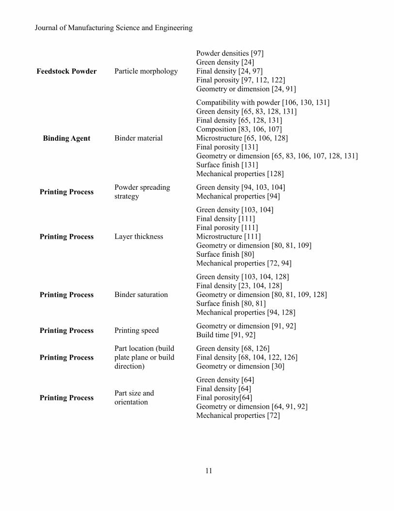
Table 2. Investigated binder jetting factors and related properties
Category Factor Related properties
Feedstock Powder Particle size
Compatibility with binder [108]
Powder densities [23, 91, 108, 111]
Green density [63, 64, 68-70, 84, 91, 108, 111, 121,
126]
Final density [23, 25, 63, 64, 68, 69, 84, 91, 97, 126]
Final porosity [68, 69, 84, 97, 121, 126]
Surface finish [91, 108]
Oxidation [68, 70, 126]
Microstructure [25, 68, 69, 84, 91, 126]
Geometry or dimension [23, 25, 63, 68, 69, 84, 91,
108, 121, 126]
Mechanical properties [91, 97, 104, 121]
Feedstock Powder Particle size
distribution
Powder densities [63]
Green density [68, 69, 126]
Final density [63, 68, 69, 97, 126]
Microstructure [69]
Geometry or dimension [63, 69, 121]
Mechanical properties [121]
Journal of Manufacturing Science and Engineering
11
Feedstock Powder Particle morphology
Powder densities [97]
Green density [24]
Final density [24, 97]
Final porosity [97, 112, 122]
Geometry or dimension [24, 91]
Binding Agent Binder material
Compatibility with powder [106, 130, 131]
Green density [65, 83, 128, 131]
Final density [65, 128, 131]
Composition [83, 106, 107]
Microstructure [65, 106, 128]
Final porosity [131]
Geometry or dimension [65, 83, 106, 107, 128, 131]
Surface finish [131]
Mechanical properties [128]
Printing Process Powder spreading
strategy
Green density [94, 103, 104]
Mechanical properties [94]
Printing Process Layer thickness
Green density [103, 104]
Final density [111]
Final porosity [111]
Microstructure [111]
Geometry or dimension [80, 81, 109]
Surface finish [80]
Mechanical properties [72, 94]
Printing Process Binder saturation
Green density [103, 104, 128]
Final density [23, 104, 128]
Geometry or dimension [80, 81, 109, 128]
Surface finish [80, 81]
Mechanical properties [94, 128]
Printing Process Printing speed Geometry or dimension [91, 92]
Build time [91, 92]
Printing Process
Part location (build
plate plane or build
direction)
Green density [68, 126]
Final density [68, 104, 122, 126]
Geometry or dimension [30]
Printing Process Part size and
orientation
Green density [64]
Final density [64]
Final porosity[64]
Geometry or dimension [64, 91, 92]
Mechanical properties [72]

Journal of Manufacturing Science and Engineering
12
Debinding and
Sintering Processes Processing time
Final density [23, 63, 64, 97, 104]
Composition [104]
Geometry or dimension [30, 63, 64, 70, 98, 104]
Surface finish [104]
Mechanical properties [104]
Debinding and Sintering
Processes Processing temperature
Final density [23-25, 30, 63, 64, 68, 69, 71, 97, 104,
111, 112, 120, 126, 131, 143]
Final porosity [69, 111, 120, 143]
Composition [120]
Microstructure [24, 25, 69, 71, 111, 112, 143]
Geometry or dimension [23-25, 63, 64, 69-71, 89, 98,
101, 104, 111, 112]
Surface finish [104]
Mechanical properties [23, 24, 70, 71, 97, 104, 112,
121, 143]
Debinding and Sintering
Processes Heating rate Geometry or dimension [89, 98]
Debinding and Sintering
Processes Atmosphere
Final density [23, 70, 116]
Porosity [116]
Composition [70, 116]
Microstructure [70, 116]
Oxidation [23, 70, 86, 116]
Geometry or dimension [23]
Other Sintering additives and
infiltrants
Final density [30, 70-72, 101]
Microstructure [30]
Geometry or dimension [30, 70, 71, 101]
Surface finish [30, 70]
Mechanical properties [70, 71]
3.2 Material-Related Factors
3.2.1 Particle Size and Its Distribution
Particle size and its distribution noticeably affect the flowability and the sinterability of powder, which are the
dominant properties in the printing and post-processing of binder jetting, respectively. A good flowability
facilitates the powder spreading process during printing [61]. The powder flow characteristics can be measured
using flowmeters (e.g., Hall flowmeter funnel or Carney funnel), according to the ASTM standard [146-148]. As

Journal of Manufacturing Science and Engineering
13
an alternative, the ratio (Hausner ratio, 𝐻𝑅) of apparent density (𝜌𝑎𝑝) to tap density (𝜌𝑡), which is defined by
Equation (1), has been used to compare the flowability between different powders [149].
𝐻𝑅 = 𝜌𝑡
𝜌𝑎𝑝 (1)
The smaller the 𝐻𝑅, the better the flowability. Bai et al. investigated the flowability of powders with different
average sizes of 77.9 μm, 26.4 μm, and 5.5 μm, which demonstrated 𝐻𝑅 of 1.16, 1.25, and 1.33, respectively
[63]. Finer powder generally demonstrates a lower flowability due to the more significant effects of particle
interactions (e.g., van der Waals, electrostatic, and capillary interaction) [10, 64, 68, 84, 91, 97, 150]. In contrast,
the flow of powder with a larger particle size is less affected by the interparticle forces due to the larger inertia
and fewer contact points.
With different particle sizes, the powders could have distinct impacts on the powder bed and green parts.
When spreading spherical Inconel 718 powder, Turker et al. found that the printer had no spreading issue with the
coarse powder (<53 μm), however, it failed to spread the fine powder (<20 μm) due to powder agglomeration
[111]. The powder spreading issues caused by the presence of agglomerated fine powders were reported by many
other researchers [68, 84, 97]. The agglomeration of fine powder particles leaves more pores in the powder bed,
thus decreasing the green density. According to Turker et al., parts printed from the fine powders achieved very
low green densities due to the spreading difficulty [111]. Similar dependency of green density on particle size was
observed in other experiments: a higher green density can be achieved by coarse powder than fine powder.
Dourandish et al. reported that the 75 μm Co-Cr-Mo powder yielded a relative green density of 54% whilst the
20 μm powder yielded a lower green density of 49% [84]. On some newly released binder jetting printers, the
spreading difficulty with fine powder is mitigated by advanced spreading mechanisms, such as ultrasonic
recoating and powder compaction, which can significantly reduce the printable particle size to lower than 5 µm
[26, 151].

Journal of Manufacturing Science and Engineering
14
The particle size has a critical impact on the inherent sinterability of powder. Sinterability can be used to
evaluate the sintering performance of powder. Sinterability is defined by Equation (2) [9],
𝜑 = 𝜌𝑠 − 𝜌𝑔
𝜌𝑡ℎ − 𝜌𝑔 (2)
where 𝜌𝑠, 𝜌𝑔, and 𝜌𝑡ℎ are the sintered density, green density, and theoretical density. Fine powder typically has
a high sinterability. The increased surface area of fine powder allows for higher sintering driving forces [63]. For
instance, the sintering neck of the 7 μm Inconel 718 powder developed to near the particle size at 1230 °C while
that of the 70 μm powder was still invisible [25].
The particle size distribution (PSD) also has a direct influence on both the printing and sintering processes.
Mixing different unimodal powders can improve powder packing and green density. Bai et al. mixed coarse and
fine copper powders with a 73:27 or 27:73 weight ratio by a rotating drum [63]. Both the apparent density and
tap density of coarse powders (77.9 μm, 26.4 μm and 17 μm) increased by adding 27 wt.% of 17 μm or 5.5 μm
fine powders. In the meantime, adding 27 wt.% of coarse powder (26.4 μm) to the fine powder (5.5 μm) could
substantially increase the green density from 44% to 51.4%. The work by Mostafaei et al. compared the green
and sintered Inconel 625 parts from powders with different PSDs [69]. Unlike the wide PSD powder (16-63 μm)
which yielded nearly a full density when sintered at 1285 °C, the powders with narrower PSDs (16-25 μm and
53-63 μm) showed more incomplete sintering areas.
3.2.2 Particle Morphology
Owing to its influence on the spreading and powder arrangement in a powder bed, the shape of the powder
particles affects the powder bed condition, green density, and final density. Spherical powder is preferred in binder
jetting due to the low internal friction and thus good flowability [61]. Verlee et al. found that both green density
and the average of apparent density and tap density of the non-spherical powder were only the half of those of the
spherical one [97]. Haeri et al. studied the effects of particles with various aspect ratios on the powder bed density

Journal of Manufacturing Science and Engineering
15
and surface smoothness using discrete element method (DEM) [152]. The highest density was obtained by rod-
shaped particles with an aspect ratio of 1.5 for roller spreading while by spherical particles for blade spreading.
The surface smoothness decreased with increasing aspect ratio for both roller and blade spreading. The
sinterability of spherical powder is considered to be better than that of powder in irregular shapes because of the
more effective powder packing [24, 97, 122]. It is possible that the irregular-shaped powder has less interparticle
contact area, and therefore, leaving more and larger pores in the green part.
Thus, many researchers used atomized powders for binder jetting because of their high sphericity [23, 24, 63].
Schade et al. and Mostafaei et al. compared the gas-atomized and water-atomized powders and reached the same
conclusion that the gas-atomized powder is more spherical and preferred for binder jetting [24, 153]. According
to Mostafaei et al., the difference in particle morphology of water-atomized and gas-atomized powders can affect
the green density [24]. The green part from water-atomized powder exhibited a relative density of 42% while the
gas-atomized obtained an increase to 55% [24].
3.2.3 Binder Materials
Since the geometry of the part is formed through the deposition of binding agents, the binder plays a key role
in the quality of binder jetting parts. Utela et al. summarized eight available binder classes, including acid/base,
hydration based, metal salts, inorganics, organics, phase changing materials, solvent, and thermal behavior
alteration [62]. The compatibility of binder and powder is critical for successful printing. The main criteria of
binder selection are the wettability and permeation ability which determine the spreading of binder in a powder
bed and the strength of green part [61, 62, 130]. Figure 5 illustrates the binder-powder interaction and binder
deposition process. Starting with the initial contact with the powder bed (Figure 5(a)), the binder droplet
permeates the powder bed (Figure 5(b)) and form the powder into agglomerates (primitives) within and between
the printing layers [130, 154]. The newly deposited droplets overlap with the previous one to ensure a continuous

Journal of Manufacturing Science and Engineering
16
bonding (Figure 5(c)). The binder deposition is controlled by the droplet volume as well as the spacing between
binder droplets.
Figure 5. Illustration of binder deposition and powder primitive formation
Two other binder selection criteria concern the debinding and sintering temperatures and the residue
composition. For most binders which require full decomposition before sintering, a distinct temperature gap
between the binder decomposition and powder sintering is necessary [128]. The decomposed binder could leave
a residue that affects the composition of the base material. For example, carbon- or oxygen-rich residues form
carbides or oxides that degrade the microstructure of materials like Ti-6Al-4V [86], Inconel 625 [24], and stainless
steels [70, 86].
A binder-powder compatibility test should be conducted to identify a suitable binder for the feedstock powder.
Figure 6 shows three different methods to examine the binder-powder interaction. Two benchtop tests were
summarized and introduced by Utela et al. [61]. As shown in Figure 6(a), the binder is introduced to a pile of
feedstock powder using a syringe. The strength of the binder-powder mixture is then evaluated after drying. Figure
6(b) illustrates another method that manually mixes the binder and powder with a designated ratio. Then the
strength and edge sharpness of the mixture are examined after shaping it into a bar or a cube. Alternatively, the
contact angle of binder and the powder bed was introduced to indirectly evaluate the binder compatibility by
Stevens et al., as shown in Figure 6(c) [122]. A low contact angle shows a good binder-powder wettability and
thus is considered to be compatible. A suitable binder material should be absorbed by the powder easily and
provide the green part with enough bonding after curing. A thermogravimetric analysis (TGA) can be carried out
to examine the decomposition or sintering characteristic once a new binder-powder system is selected.
Journal of Manufacturing Science and Engineering
17
Figure 6. Binder-powder compatibility tests [61, 122]
3.3 Process-Related Parameters
3.3.1 Layer Thickness
Layer thickness is an important process parameter that controls the amount of powder spread onto each layer of
the powder bed. The selection of layer thickness is dependent on the powder particle size [62]. Meier et al. applied
discrete element method (DEM) that involved particle-to-particle and particle-to-wall interactions to simulate the
powder spreading process [155]. They found that both the density and surface smoothness of the powder bed can
be improved by increasing the layer thickness. A layer thickness of approximately three times the maximum
particle size is considered to be optimal due to the sufficient space for the powder rearrangement and less influence
from the top and bottom boundaries. Dourandish et al. reported their spreading experiments of fine (20 μm) and
coarse (75 μm) powders with different layer thicknesses (75 μm, 100 μm, and 150 μm) [84]. The best printing
quality was obtained at a layer thickness of 75 μm for the fine powder and 150 μm for the coarse powder. Using
Inconel 718 powder of 26 μm, Turker et al. studied the density of parts printed with different layer thicknesses
but sintered at the same temperature (1260 °C) [111]. The density of the parts with 200 μm layer thickness was
about 88% while that with 100 μm layer thickness was about 92%. Shrestha et al. tested the transverse rupture
strength of sintered stainless steel 316L samples with variable layer thicknesses [94]. The strength obtained a
trend that first increased and then slightly decreased when the layer thickness was changed from 80 μm to 100
μm and 120 μm and the powder particle size was maintained at 30 μm.
3.3.2 Binder Saturation
Binder jetting controls the deposition of binder via the level of binder saturation (Sa), which is the volume
fraction of binder in the void space within a predefined powder bed, as defined by Equation (3),

Journal of Manufacturing Science and Engineering
18
𝑆𝑎 = 𝑉𝑏
𝑉𝑣=
𝑉𝑏
(1 − 𝜌𝑝𝑏′) × 𝑉𝑝𝑏
(3)
where the 𝜌𝑝𝑏′ represents the relative packing density of the powder bed, 𝑉𝑝𝑏 is the volume of the predefined
powder bed, 𝑉𝑏 represents the volume of the binder, and 𝑉𝑣 is the volume of the void spaces. Relative packing
density refers to the volume fraction of powder in the powder bed, which is defined by Equation (4),
𝜌𝑝𝑏′ =
𝑉𝑝
𝑉𝑝 + 𝑉𝑣 (4)
where 𝑉𝑝 is the volume of the powder in the powder bed.
Binder saturation affects surface quality and dimensional and geometric accuracy. Inadequate binder
saturation (i.e., undersaturation) can cause powder to drop from the green part and deteriorate the surface finish
and dimensional and geometric accuracy [80, 81]. If the binder saturation is too high (i.e., oversaturation), the
binder may migrate to outside the defined area (a phenomenon commonly called bleeding), bonding excessive
powder and thus worsening surface finish and dimensional and geometric accuracy as well [80, 81].
Binder saturation also influences the density and mechanical properties. Undersaturation can cause inadequate
bonding between layers or within one layer, leaving pores in the part that could deteriorate the properties [94].
Shrestha et al. tested the transverse rupture strength of stainless steel 316L samples printed with different binder
saturations (35%, 70%, 100%) [94]. They reported that the strength of sintered samples was obviously lower for
the 35% binder saturation than that for the others. Oversaturation leads to a lower volume fraction of powder and
creates more pores after debinding [23]. Thus, the neck formation during sintering is hindered, resulting in
decreased sintered density. But if the binder saturation is within a suitable range, there is no obvious impact on
the sintered density because of the binder removal process (debinding). As reported by Bai et al., both 60% and
80% binder saturation provided similar sintered densities for the same copper powders with a particle size of 15
μm [23].
Journal of Manufacturing Science and Engineering
19
To predict the suitable binder saturation, a physics-based model was developed by Miyanaji et al. to estimate
the capillary pressure based on the binder-powder interaction in the equilibrium state [156]. The predicted binder
saturation agreed well with the experimental results on Ti-6Al-4V. This work indicates that the binder-powder
interaction in the powder bed is driven by the capillary pressure over the interfaces of binder and air. Therefore,
the selection of binder saturation should consider the interactions of binder, powder, and air.
4 DENSITY
The density of additively manufactured parts is one of the essential properties driving the quality of functional
parts. Pores in the parts concentrate the local stresses, thus deteriorating the mechanical performance [157].
Different terminologies of density and porosity and their definitions were summarized by Du et al. [10]. This
section discusses the densities in different stages with a focus on the effects of the critical factors and then
summarizes the densities of the feedstock powder, powder bed, green part, and final part obtained by different
post-processing technologies reported in prior works.
4.1 Powder Bed Density
Like many other powder-bed-based AM technologies, powder bed density is a critical factor of the binder
jetting process. The powder bed density demonstrates how dense a predefined powder bed region is. For example,
if the powder bed density is 55%, there is void space of 45% in powder bed region.
4.1.1 Measurements of Powder Bed Density
There are a few methods to measure the powder bed density. For example, a number of researchers printed a
cup in the powder bed [63, 91, 119]. The powder bed density is calculated by dividing the mass of the powder
contained in the cup by the volume of the cup. It is important to remove powder from the cup completely before
weighing. Another measurement, reported by Ziaee et al., involves spreading a number of layers of powder on
the build platform. Once the powder is spread, a tube with thin walls and sharp edges is vertically inserted into

Journal of Manufacturing Science and Engineering
20
the powder bed. The mass of the powder contained in the tube is measured after removing the powder around
[101]. The final powder thickness in the tube has to be measured accurately.
4.1.2 Factors of Powder Bed Density
The powder flowability and the powder spreading condition are the two main factors affecting powder bed
density. As mentioned in Section 3, powder flowability can be influenced by particle size, distribution, and
morphology [24, 63, 69, 97, 119, 152]. Besides the inherent powder properties, there are reports on the effects of
the spreading process on the formation of powder bed. Using discrete element method (DEM), Haeri et al.
simulated the powder spreading process using rod-shaped particles with various aspect ratios to examine the
effects of spreader type, spreading velocity, and layer thickness [152]. Their results showed that both the powder
bed density and surface smoothness were more significantly affected by the spreader type and spreading velocity
than the layer thickness. Budding et al. and Rishmawi et al. experimentally investigated the powder bed densities
achieved via different shapes and motions of powder spreader [104, 158]. The counter-rotating roller demonstrates
higher powder bed density and smoother surface than the forward-rotating roller, static roller, and blade. Budding
et al. claimed that the combination of blade and forward-rotating roller has the potential to achieve a higher
powder bed density than that using a counter-rotating roller [158]. A roller with a larger diameter or a blade that
has a wider head profile is also beneficial because of the increased compaction area and pressure [152, 159]. The
powder spreading velocity and layer thickness are the two major process-related parameters that affect powder
bed density. DEM simulations demonstrated that slower powder spreading and decreasing layer thickness both
lead to a denser and smoother powder bed [152, 160].
4.1.3 Density Variations within Powder Bed
A uniform powder bed ensures a consistent part quality in binder jetting. However, density variations in
powder bed have been reported. Do et al. reported that the shrinkage of green parts varied with regards to the
location of the powder bed [30]. They explained that, due to the movement of the roller spreading mechanism,
Journal of Manufacturing Science and Engineering
21
the powder was pushed towards the end of the build platform. More powder was accumulated and therefore higher
localized powder bed density occurred at the further end from the powder supply, causing the green density
difference and thus the shrinkage variation.
Lee et al. reported the downward displacement of the powder bed caused by compressive pressure (e.g., the
weight of subsequent layers) [161]. The displacement of powder layers was a function of particle morphology
and packing density. It was found that the displacement was more significant for the middle region of powder bed
compared to the top or bottom region. This downward displacement could raise concerns about the powder bed
uniformity.
4.2 Green Density
Geometry method is commonly used to measure the green density of regular shapes (e.g., cubes and
cylinders). For parts with complex shapes, geometry method can be inaccurate. In this case, computed
tomography (CT) could be used. The green density of binder jetting parts is usually 40–60% of the theoretical
density. Once the printing process is finished, the green part typically consists of more than 30 vol.% voids and
10 vol.% binder [61]. The green density plays a key role in the final density and the shrinkage induced by the
densification post-processing. Since the part is printed from the powder bed, the quality of green part is governed
by the density and uniformity of powder bed. Therefore, the factors (i.e., powder flowability and powder
spreading condition) influencing the powder bed density lead to consistent consequences to the green density.
The detailed effects of the two major types of factors are discussed in Section 4.1.2.
4.3 Sintered Density
The driving force for the densification in sintering is the reduction in surface energy. The powder with a large
specific surface area (e.g., fine powder) is preferred for densification. For example, the fine spherical stainless
steel 316L powder (38 µm) obtained a density of 89.4% after sintered at 1432 °C for 90 min while the coarse

Journal of Manufacturing Science and Engineering
22
spherical powder (73 µm) obtained only a density of 71.6%, though both powders had similar powder bed
densities [97]. The detailed effects of powder properties on sintered density are discussed in Sections 3.2.1 and
3.2.2.
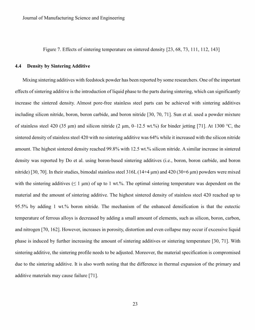
In addition to the powder properties, the sintering temperature and time have direct impacts on the
densification. As presented in Figure 7, the higher sintering temperature yields a higher sintered density as sintered
density is determined by the amount of energy provided to the sintering. The required sintering temperature varies
with the composition, powder properties, and application, as discussed in Section 2.2.1. For example, the sintering
behavior of Inconel 718 parts was discussed in the study of Nandwana et al. [25]. At 1185 °C, no obvious neck
formation occurred in the 21 μm and 70 μm powders because only initial sintering stage was reached. As the
sintering temperature increased to 1230 °C, intermediate-stage sintering was activated on both powders where
the mass started to transport between the contacting particles. As the sintering temperature increased from 1290
°C to 1330 °C, the sintered density of 21 μm powder reached 99.7% as the relatively large and tubular pores were
reduced to small and spherical ones. Meantime, a sufficient sintering time is required for the neck growth between
the powder particles. Bai et al. sintered the copper green parts in a mixed hydrogen and argon atmosphere for
different sintering times [23]. By increasing the sintering time from 120 min to 360 min, the sintered density
increased from 76% to 81%. Longer sintering time and higher sintering temperature could potentially increase
the final density whilst the grain size may grow remarkably. Mostafaei et al. measured the grain sizes of Inconel
625 samples sintered at different temperatures for 4 h [24]. The samples sintered at 1225 °C had a relative density
of 85% with a grain size of 39 ± 4 μm. As the temperature increased to 1300 °C, the sintered density increased to
99% whilst the grain size grew by about four times to 106 ± 27 μm.
Journal of Manufacturing Science and Engineering
23
Figure 7. Effects of sintering temperature on sintered density [23, 68, 73, 111, 112, 143]
4.4 Density by Sintering Additive
Mixing sintering additives with feedstock powder has been reported by some researchers. One of the important
effects of sintering additive is the introduction of liquid phase to the parts during sintering, which can significantly
increase the sintered density. Almost pore-free stainless steel parts can be achieved with sintering additives
including silicon nitride, boron, boron carbide, and boron nitride [30, 70, 71]. Sun et al. used a powder mixture
of stainless steel 420 (35 μm) and silicon nitride (2 μm, 0–12.5 wt.%) for binder jetting [71]. At 1300 °C, the
sintered density of stainless steel 420 with no sintering additive was 64% while it increased with the silicon nitride
amount. The highest sintered density reached 99.8% with 12.5 wt.% silicon nitride. A similar increase in sintered
density was reported by Do et al. using boron-based sintering additives (i.e., boron, boron carbide, and boron
nitride) [30, 70]. In their studies, bimodal stainless steel 316L (14+4 μm) and 420 (30+6 μm) powders were mixed
with the sintering additives (≤ 1 μm) of up to 1 wt.%. The optimal sintering temperature was dependent on the
material and the amount of sintering additive. The highest sintered density of stainless steel 420 reached up to
95.5% by adding 1 wt.% boron nitride. The mechanism of the enhanced densification is that the eutectic
temperature of ferrous alloys is decreased by adding a small amount of elements, such as silicon, boron, carbon,
and nitrogen [70, 162]. However, increases in porosity, distortion and even collapse may occur if excessive liquid
phase is induced by further increasing the amount of sintering additives or sintering temperature [30, 71]. With
sintering additive, the sintering profile needs to be adjusted. Moreover, the material specification is compromised
due to the sintering additive. It is also worth noting that the difference in thermal expansion of the primary and
additive materials may cause failure [71].

Journal of Manufacturing Science and Engineering
24
4.5 Density by Infiltration Process
Infiltration can be applied to increase the final part density. Inaekyan et al. infiltrated bronze into cured iron
parts at 1100 °C in argon and achieved a final density of 85% with a transverse rupture strength 25 times better
than the iron parts processed by HIP [73]. In the work by Doyle et al., the cured stainless steel 420 samples were
infiltrated with tin-bronze (90 wt.% copper and 10 wt.% tin) at ~1100 °C in an argon atmosphere [72]. Liquid
phase sintering of the tin-bronze infiltrant was observed. A low porosity (~1%) of the composite was measured
by optical microscopy. Tungsten and stainless steel (316L and 420) obtained a density of above 95% after
infiltrated with bronze, as reported by ExOne [110]. However, similar to the effect of adding sintering additives,
the purity has to be sacrificed in this case.
4.6 Summary of Achieved Density
Due to the sequential steps involved, density should be tracked through each of the steps to understand the
whole process. Table 3 summarizes the density evolution during the entire process chain and its correlation with
the particle size. The reported materials include cobalt alloys, pure copper, nickel-based alloys, pure iron and
ferrous alloys, pure titanium and its alloy, and tungsten. About 60% of prior works that investigated densification
have demonstrated the possibility of reducing porosity to less than 10%. The studies on the effects of particle size
and its distribution pointed out their significance to the densities. With parameter optimization and a suitable
sintering process, ten materials have been proven to achieve a density of higher than 90%. The highest relative
density achieved for each material is listed in Table 4. However, the number of materials that have reached a high
density in binder jetting is still very limited compared with those in other metal AM processes such as powder
bed fusion and directed energy deposition.
Table 3. Powder, green, and sintered densities of different materials with their feedstock powder particle
sizes

Journal of Manufacturing Science and Engineering
25
Material Particle
size (μm)
Powder
density
(%)
Green
density
(%)
Sintered
density
(%)
Density by
other
densification
techniques
(%)
Note Reference
Co-Cr-
Mn 20 P*: 53 49 75 /** / [84]
Co-Cr-
Mn 75 P: 53 53 81 / / [84]
Co-Cr-
Mn 72.5 ± 21.2 / 44.1 97.2 / / [143]
Cu 15.3 P: 56 / 85.5 / / [23]
Cu 16.5 P: 63 / 77.6 / / [23]
Cu 75.2 P: 55 / 63.2 / / [23]
Cu
Bimodal 5
(73 wt.%) +
30
A: 54.4,
T: 61.2 51.4 92.3 / / [64]
Cu
Bimodal 15
(73 wt.%) +
5
A: 54.6,
T: 67.4 53.4 85.5 / / [63, 64]
Cu
Bimodal 30
(73 wt.%) +
5
/ / 90.8 / / [129]
Cu
Bimodal 30
(73 wt.%) +
5
A: 53.7,
T: 63.9 52.2 87.1 / / [63, 64]
Cu
Bimodal 30
(73 wt.%) +
5
/ / / 99.9 Treated with HIP [64]
Cu
Bimodal 75
(73 wt.%) +
15
A: 59.7,
T: 66.9 57.2 74.5 / / [63, 64]
Cu 17 / 47 87.4 /
Cu
nanosuspension
as binder
[65, 128]

Journal of Manufacturing Science and Engineering
26
IN 625 22.5 (16–
25) / 45 98.2 / / [69]
IN 625 31.8 (16–
63) / 51.5 99.9 / / [69]
IN 625 31.8 (16–
53) / 53 99.6 / / [112]
IN 625 32 (18.6–
44.2) / 55 99.2 / / [24]
IN 625 32 / / >99 / / [114]
IN 625 32 / / 98.9 / / [113]
IN 625 34.5 (17.6–
53.6) / 42 95 / / [24]
IN 625 53.1 (53–
63) / 47.5 97.5 / / [69]
IN 718 7.09 / / 99.9 / / [25]
IN 718 19.75 / / 92 / / [25]
IN 718 65.72 / / 99.9 / / [25]
IN 718 26 (<53) A: 50,
T: 63.4 / 99 / / [117]
IN 718 26 (<53) A: 50,
T: 63.4 / 98.5 / / [111]
Ni-Mn-
Ga ~25 / / 66.3 /
Ball milled
magnetic shape
memory material
[115]
Ni-Mn-
Ga ~40 / / ~55 /
Ball milled
magnetic shape
memory material
[116]
Ni-Mn-
Ga <63 / / 99 /
Ball milled
magnetic shape
memory material
[120]
Iron 34.1 (<63) / 48.1 91.3 / Mixed with 1
wt.% PVA [103, 104]
Iron 29.1 A:44.3,
T:50.7 40 43 / / [73]

Journal of Manufacturing Science and Engineering
27
Iron 29.1 A:44.3,
T:50.7 40 / 53 Treated with HIP [73]
Iron 29.1 A:44.3,
T:50.7 40 / 82
Infiltrated with
bronze [73]
SS 17-
4H <15
T:52.8
P:43 43 ~100
Coated with
polymer
ammonium
polymethacrylate;
Vibration
spreading
employed
[105]
SS 17-
4H / / / 98 /
Provided by
ExOne [110]
SS 304L / / / 97 / Provided by
ExOne [110]
SS 316L / / / 98 / Provided by
ExOne [110]
SS 316L / / / / >95
Provided by
ExOne;
Infiltrated with
bronze
[110]
SS 316L Bimodal 14
(60 %) + 4 P: ~60 60 / ~99
Mixed with 1
wt.% BN
additive; Sintered
in vacuum
[70]
SS 316L 14 (5–25) P: 51 53 80 / / [91]
SS 316L 15–30 P: 57 / 78 / / [90]
SS 316L 20 P: 53 52 88 / / [84]
SS 316L <22
A:44,
T:55,
P: 56.5
56.5 93.9 / / [101]
SS 316L 22 P: 58.6 / 97.5 / / [97]
SS 316L 30 (22–43) / / 50 / Lattice structure [95]
SS 316L 30 / / 52.4 / / [100]

Journal of Manufacturing Science and Engineering
28
SS 316L 31 P: 57.6 / 98.7 / / [97]
SS 316L 45–90 P: 55.5 / 71.6 / / [97]
SS 316L 55
A:41,
T:48, P:
56
/ 96 /
Cured
agglomerate of
powder <22 μm
as feedstock
[101]
SS 316L 75 P: 53 54 80.5 / / [84]
SS 316L 78 (44–106) P: 61 58 72 / / [91]
SS 420 / / / / 95
Provided by
ExOne;
Infiltrated with
bronze
[110]
SS 420 30 / / / 96.98 Mixed with 1
wt.% B additive [30]
SS 420 30 / / / 99
Infiltrated with
0.45 vol.%
bronze
[72]
SS 420 35 (22–53) / 57 / 99.8
Mixed with 12.5
wt.% Si3N4
additive
[71]
SS 420 Bimodal 30
(60 %) + 6 P: ~60 60 / 99.6
Mixed with 1
wt.% BN
additive; Sintered
in vacuum
[70]
Fe-Mn <44 / / 60.5 / Ball milled bio-
material [88]
Fe-Mn-
Ca <44 / / 47.1 /
Ball milled bio-
material [88]
Ti 45–75 / / 68 / Mixed with 3 or
5 wt.% PVA [121]
Ti 45–150 / / 59 / Mixed with 5
wt.% PVA [121]
Ti 45–106 / 47.9 70.5 / Mixed with 3
wt.% PVA [68]

Journal of Manufacturing Science and Engineering
29
Ti 75–90 / / 71.7 /
Graded material;
Mixed with 3
wt.% PVA
[125]
Ti 106–150 / 57.6 71.5 / Mixed with 3
wt.% PVA [68]
Ti
bimodal: 0–
45 (50
wt.%) +
106–150
/ 53 84.6 / Mixed with 3
wt.% PVA [68]
Ti
bimodal: 0–
45 (50
wt.%) + 45–
106
/ 45.9 82.7 / Mixed with 3
wt.% PVA [68]
Ti6Al4V 44–147 / / 81.9 / / [122]
W / / / / 97
Provided by
ExOne;
Infiltrated with
bronze
[110]
Note: * A: apparent density, T: tap density, P: powder bed density; ** /: Not specified
Table 4. Materials with reported relative final density of higher than 90%
Material Number of articles Highest relative density (%)
Iron 1 [104] 91.3
Stainless steel 17-4PH 1 [110] 98
Stainless steel 304L 1 [110] 97
Stainless steel 316L 5 [70, 97, 101, 110] 98.7
Stainless steel 420 5 [30, 70-72, 110] 99.8
Inconel 625 5 [24, 69, 112-114] 99.9
Inconel 718 3 [25, 111, 117] 99.9
Ni-Mn-Ga 1 [120] 99
Copper (Cu) 3 [64, 129] 99.9
Tungsten (W) 1 [110] 97

Journal of Manufacturing Science and Engineering
30
5 DIMENSIONAL AND GEOMETRIC ACCURACY
5.1 Dimensional Accuracy
The dimensional accuracy of binder jetting parts might be affected by the characteristics of powder and binder
materials and process-related parameters [30, 70, 80, 81, 91, 92, 108, 127, 156]. Some of the processing
parameters, including printing orientation and speed, binder saturation, and layer thickness have been empirically
studied [80, 81, 91, 92, 105, 127, 156]. Seluga reported that the use of vector printing on the part outlines followed
by filling the content using raster printing can possess a better surface definition compared to a complete raster
printing [105]. Miyanaji et al. reported that the printing orientation and speed have impacts on the dimensional
accuracy due to the initial velocity of binder droplets from the printhead [92]. They investigated the accuracy of
the formation of single and multiple tracks with different printing orientations and speeds. The widths of tracks
printed along the direction of printhead movement were more dimensionally accurate and consistent than those
oriented perpendicularly to the movement direction. With increasing printing speed, the width of printed tracks
decreased, and the consistency became worse as more unsaturated spots were observed on the tracks. Lu and
Reynolds investigated the effects of binder saturation and layer thickness on the dimension of printed TiNiHf
meshes using powders of 5.5 µm [127]. Three binder saturations (55%, 110%, and 170%) and layer thicknesses
(20 µm, 35 µm, and 50 µm) led to different mesh widths, which were falling in the range of 280–340 µm while
the designed is 200 µm. Bleeding was more pronounced at 20 µm layer thickness due to oversaturation. The most
accurate mesh was printed with 35 µm layer thickness and 55% binder saturation achieving average width of 280
µm with the best consistency among all samples.
One of the biggest concerns that aggravate the dimensional accuracy is the shrinkage induced during sintering
[23, 70, 72, 105]. To achieve a high final density, green parts must be sintered to at least the intermediate stage
where the powder undergoes significant diffusion. As a result, shrinkage occurs due to the reduction of pores via

Journal of Manufacturing Science and Engineering
31
grain boundary diffusion and volume diffusion of particles. Volumetric shrinkage (𝑆) is given by the relative
volume change before and after sintering, i.e., the relative difference between green (𝑉𝑔) and sintered (𝑉𝑠) volumes:
𝑆 =𝑉𝑔 − 𝑉𝑠
𝑉𝑔
= 1 −𝑉𝑠
𝑉𝑔 (5)
Mass is conserved in most sintering processes without considering the weight loss during debinding. In this
case, the volumetric shrinkage can be rewritten as
𝑆 = 1 −𝜌𝑔
𝜌𝑠 (6)
This equation implies that the shrinkage dictates the ratio of green density to sintered density. In other words,
densification is at the expense of increasing shrinkage given the same green density.
Figure 8 shows the shrinkages of different materials with the green and sintered densities. The volumetric
shrinkage is calculated if linear shrinkages are reported. Most samples with relative sintered density over 80%
have an average volumetric shrinkage of higher than 40% as most of green densities are 40–55%. This paper finds
that the attainable density of green part may not be greater than 60% due to the non-optimal spreading process
and the powder packing limitation. Some possible modifications to further retain the dimensions of the part are
discussed in Section 7.3.
Figure 8. Shrinkage and relative densities of binder jetting parts [23-25, 63-65, 69, 73, 88, 101, 112, 114,
117, 121, 125, 128]
Many researchers have investigated the relationship between the level of shrinkage and the properties of the
feedstock powder [25, 63, 69, 84, 97, 122]. Nandwana et al. evaluated the shrinkage of sintered Inconel 718 parts

Journal of Manufacturing Science and Engineering
32
from gas atomized powders with different sizes [25]. The fine powder (7 μm) obtained an increase in shrinkage
from 31 vol.% at 1185 °C to 46 vol.% at 1290 °C. However, for the coarse powder (70 μm), no obvious
dimensional change was observed until the temperature became higher than 1230 °C. It is indicative of the better
sinterability of the fine powder, leading to higher shrinkage. Mostafaei et al. investigated the shrinkage of three
Inconel 625 powders with different mean sizes and size distributions [69]. They reported that the green density
was 45% for the fine powder (16–25 μm), 48% for the coarse powder (53–63 μm), and 52% for the powder with
a wide particle size distribution (16–63 μm). For sintering temperatures below 1270 °C, the sintered density of
fine powder was higher than those of the other two powders. The fine powder also led to the larger shrinkage after
sintering at temperatures from 1225 °C to 1285 °C. The higher sintered density and larger shrinkage of the fine
powder are probably due to its higher sinterability. The addition of nanoparticles to the green part was found to
mitigate the shrinkage level through increasing the green density [65, 75, 79, 128, 131]. Bai et al. reported that,
after adding copper nanoparticles to an organic binder, the sintered density was similar to that without
nanoparticles while the shrinkage decreased [128]. The reason is that the jetted nanoparticles fill the powder bed
voids, thus increasing the green density and decreasing the sintering shrinkage.
In addition to the overall dimensional deviations after sintering, the linear shrinkage along the build direction
(z-axis) was observed to be greater than that in the powder bed plane (x-y plane) [64, 69]. Two possible reasons
are: 1) the presence of more porosity in the z-direction than in the x-y plane due to the layering process and the
spreading of binder and 2) the gravity effect during sintering process. Non-uniform shrinkage after sintering is
another issue for metal AM parts [71, 75]. In binder jetting, the sintering could be very different from what has
been studied in traditional powder metallurgy due to the complicated geometry.

Journal of Manufacturing Science and Engineering
33
5.2 Geometric Accuracy
In the current literature, only a few studies reported the accuracy of the parts with complex geometries. Sun
et al. measured the inner corner angle of L-shaped stainless steel 420 samples and compared it to the design [71].
The as-printed samples acquired an angle of 90 ± 0.2 deg. As the sintering temperature increased above 1150 °C,
the inner corner angle was increased by 0.5–1.0 deg. The shape was more distorted with increasing temperature
as higher fraction of liquid phase formed. Geometric accuracy issues were also reported by other studies on
simpler geometries (e.g., cylinders and cubes) [30, 69, 70]. More significant shape changes (e.g., distortion or
even collapse) occurred when the sintering temperature exceeded the critical liquidation temperature. However,
there is still limited investigation of the accuracy of complex geometry.
6 MECHANICAL PROPERTIES
In contrast to PBF and DED, only a few investigations have been conducted on mechanical properties of
binder jetting parts to date. Table 5 shows the yield strength (YS), ultimate tensile strength (UTS), and elongation
reported in the literature and the datasheet provided by ExOne and Desktop Metal. Values in the parentheses are
the mechanical properties obtained by cold working. Among the surveyed papers, only eight of them investigated
the mechanical strength of parts via binder jetting. Among all of the reported mechanical strength values, more
than 30% are reported by the ExOne and Digital Metal. With the help of conventional aging treatment, the UTS
of Inconel 625 increased by 12% from 644 ± 16 MPa to 718 ± 14 MPa [24]. In particular, stainless steel 17-4H,
316L, and 420 have demonstrated an equivalent or superior UTS compared to the cold worked samples [163].
Doyle et al. [72] reported that parameter optimization for stainless steel 420 has demonstrated promising
mechanical strength that is higher than that reported by ExOne.

Journal of Manufacturing Science and Engineering
34
Table 5. Yield strength, ultimate tensile strength, and elongation of binder jetting (compared with cold working)
parts
Material Final
Density (%)
Yield Strength
(MPa)
Ultimate tensile
strength (MPa)
Elongation
(%) Reference
Iron 91.3 30.6 (50) / (540) / [164, 165]
Stainless steel 17-
4PH 98
730–1034
(980) 900–1317 (1060) 8.5–12 (8) [110, 166, 167]
Stainless steel
304L 97 205 (215) 579 (550) 60 (70) [110, 168]
Stainless steel
316L 95–98 180–224 (170) 494–582 (425) 51–61.9 (40)
[97, 110, 166,
169]
Stainless steel
316L 95* 283* (170) 580* (425) 14.5* (40) [110, 169]
Stainless steel
420 95–99*
249.9–455*
(345) 682–737.3* (655) 2.3–2.7* (25) [72, 110, 170]
Fe-Mn Alloy 60.7 189.7 228.1 / [88]
Inconel 625 98.9–99.6 327–376 (414) 612–644 (827) 40.9–47 (30) [24, 112, 170]
Inconel 625 99.2** 394** (952) 718** (1269) 29.1** (32) [24, 165]
Ti6Al4V / 790 (880) 890 (950) 8 (14) [165, 166]
Copper (Cu) 85.5 / (333) 116.7 (344) / [23, 165]
Tungsten (W) 97* 420* (750) 427* (980) 0 [110, 165]
Note: *infiltrated with bronze; ** treated by aging.
7 KNOWLEDGE GAPS AND FUTURE PERSPECTIVES
7.1 Powder Spreading Process
In binder jetting, the powder spreading process is crucial since it affects not only the density but the
homogeneity of the part. There are some studies about the effects of powder spreading process in powder-bed-
based AM [152, 158, 160, 171, 172]. Some process optimization efforts have been conducted experimentally in
binder jetting regarding the powder spreading parameters such as layer thickness and spreading speed, leading to
improved properties of the green part [72, 80, 81, 84, 94, 109, 164]. However, the underlying physical aspects in
terms of the dynamic flow behavior of the powder during spreading are very complicated and have not been
sufficiently investigated.

Journal of Manufacturing Science and Engineering
35
As discussed in Section 3.2, flowability has a noticeable influence on powder spreading and it is a function
of some critical powder properties (e.g., average particle size, particle size distribution, and particle shape) [69,
84, 111, 153, 173]. During the powder spreading process, the forces acting on the particles include the gravity,
van der Waals, and electrostatic and frictional forces between the particles. It is also known that the effects of
spreader type and spreading strategy on powder bed are significant [152, 160].
Powder segregation was observed, especially when the powder had a wide particle size distribution. Wheat et
al. used CT images to analyze the green and sintered titanium parts from plasma atomized powders with three
different sizes (0–45 μm, 45–106 μm, and 106–150 μm) and their mixtures [68]. Periodic powder heterogeneity
was observed along the z-axis. Powder particles tended to segregate depending on their sizes, thus causing the
localized variation. A cause of this periodic segregation could be that the particles with a similar size have a
similar movement during powder spreading, owing to gravity and the interparticle forces. Therefore, the
segregation of a group of similar particles from the others occurs in each layer. Further investigations are still
needed to confirm the explanation. Similar heterogeneous microstructure was also observed in Inconel 625 [69].
However, the collective effects of powder properties and spreading conditions on the dynamic flow behavior
are still not clear. Further knowledge to control and improve the powder spreading process is necessary. With the
knowledge of the resultant conditions of powder spreading process, the powder bed of binder jetting is more
predictable, leading to better mechanical properties and homogeneity for the printed parts. Moreover, the
comprehension of powder bed formation may enable delicate control of the porosity of binder jetting parts. It
could advance the application of binder jetting in a wide range of industries such as healthcare and tooling [114,
132, 174].

Journal of Manufacturing Science and Engineering
36
7.2 Binder-Powder Interaction
The interactions between the binder and powder particles significantly influence the strength and geometry of
green parts and the quality of the final parts. Stevens et al. summarized three stages of binder-powder interaction
[122]. In this review, the three stages are modified considering other studies, especially Parab et al.’s recent work
on real time observation using high-speed X-ray imaging [108, 112, 130, 154, 156, 175, 176]. In the first stage,
the powder is impacted by the jetted binder droplet. The droplet brings disturbance to the powder bed, possibly
accompanying splashing, bouncing, and powder ejection. The second stage is the binder spreading, during which
the binder migrates into the gaps between surface particles. The third stage is the capillary action of the binder
contributing to the migration to the adjacent particles until a capillary pressure equilibrium is reached. As a result,
the saturated particles are pulled together in response to the surface tension of liquid.
The binder deposition is controlled by numerous process-related parameters, including binder saturation,
printing speed, and binder drying time. Binder saturation affects surface quality, dimensional and geometric
accuracy, density, and mechanical properties of the part. The desired amount of binder deposited to a part is
coupled with the powder bed density, on which particle size and morphology show great impacts. The fine and
irregular-shaped particles generally require a higher binder saturation likely due to the lower powder bed density
[154].
Moreover, the binder can be engineered to offer more features. For example, a number of efforts have been
made to improve the density of green parts and mitigate sintering shrinkage with nanosuspension binders [65, 75,
79, 83, 128, 130]. In the series work of Bai et al., a nanosuspension binder was introduced to the green part during
printing [65, 128, 130, 131]. Both the density and strength of green parts could be enhanced by adding more
nanosuspension binder [128]. As another result, the sintered shrinkage level was decreased due to the increased
green density.

Journal of Manufacturing Science and Engineering
37
There is still a large room for the research on the binder-powder interactions. The overall effect of the binder
deposition and migration on the powder bed is not clear yet because of the limitation of predictive models for
binder-powder interaction and inadequate knowledge about the effects of process-related parameters. Therefore,
further investigation of the empirical observation coupled with modeling analysis is required to provide insight
into the binder-powder interactions. To empirically study the binder-powder interactions, high-speed video can
be used to capture the transient dynamics. The morphology and structure of binder-powder mixture can be
analyzed by the micrographs and CT images of cured parts.
7.3 Part Shrinkage
From the existing literature, the densification-induced shrinkage can lead to substantial dimensional
deviations on a variety of materials [25, 30, 69, 70, 111, 122]. Therefore, it is of importance to mitigate the impact
of high-level shrinkage to better benefit from the complex-shape manufacturing ability of binder jetting. The
requirement of a low shrinkage level and a high dimensional accuracy contradicts with the nature of densification.
To mitigate this contradiction, a higher green density is needed. One of the effective solutions is to increase the
green density by employing multimodal powders [9, 61, 63, 68, 173]. However, the sintered density may not
always increase with the increased green density [69, 97]. Multimodal powder is known to cause layer-wise
density variation [68]. The presence of localized density variation may lead to non-uniform shrinkage or even
cracking. Moreover, as discussed in Section 7.1, the optimal powder spreading mechanism and strategy can be
developed to attain a higher green density. Nanoparticles can be also introduced to the binder to increase the green
density and reduce the shrinkage level [75, 79, 128]. Another method to retain the dimension is to infiltrate the
green part [83, 85]. Ultimately, when designing parts for binder jetting, geometric and dimensional compensations
can be applied. In this case, the understanding of dimensional change in complex shapes must be developed.
Considerations need to be given to sintering parameters and other factors such as part geometry and orientation
of the part during sintering [64, 69-71].

Journal of Manufacturing Science and Engineering
38
8 SUMMARY
Over the past decade, binder jetting of metals has received increasing attention due to its low cost and high
scalability, making it a popular and viable alternative to other AM processes based on high energy beams such as
powder bed fusion and directed energy deposition. This paper summarizes the available data from both academia
and industry and analyzes the important aspects of metal binder jetting, including density and mechanical
properties. A final density higher than 90% is attainable for ten materials. A few grades of stainless steel obtained
equivalent or superior mechanical properties compared to cold working. Critical factors that affect part properties
in binder jetting are identified and correlated with the corresponding effects. Powder properties such as powder
particle size and morphology play an important role in the formation of powder bed and green part and the
densification process. Small particle size and spherical shape are proven beneficial to a high density. Approaches
like the use of multimodal powder and addition of nanoparticles to the binder have a potential to enhance the part
quality. However, the occurrence of high-level part shrinkage in contradiction to full densification is among the
most notable challenges for metal binder jetting. The fundamental knowledge related to the powder spreading
process and binder-powder interaction is inadequate.
ACKNOWLEDGEMENT
This material is based upon work supported by the National Science Foundation under Grant No. 1762341.
REFERENCES
[1] Frazier, W. E., 2014, "Metal Additive Manufacturing: A Review," Journal of Materials Engineering and Performance, 23(6),
pp. 1917-1928.
[2] Guo, N., and Leu, M. C., 2013, "Additive manufacturing: technology, applications and research needs," Frontiers of Mechanical
Engineering, 8(3), pp. 215-243.
[3] Kumar, A., Mandal, S., Barui, S., Vasireddi, R., Gbureck, U., Gelinsky, M., and Basu, B., 2016, "3D printing of ceramic
implants," Materials Science and Engineering: R: Reports, 103, pp. 1-39.
[4] Lyons, B., 2014, "Additive manufacturing in aerospace: Examples and research outlook," The Bridge, 44(3).
[5] OHJI, T., 2018, "Additive manufacturing of ceramic components," Synthesiology, 11(2), pp. 81-93.
[6] Song, Y., Yan, Y., Zhang, R., Xu, D., and Wang, F., 2002, "Manufacture of the die of an automobile deck part based on rapid
prototyping and rapid tooling technology," Journal of materials processing technology, 120(1-3), pp. 237-242.

Journal of Manufacturing Science and Engineering
39
[7] Thomas, C. L., Gaffney, T. M., Kaza, S., and Lee, C. H., 1996, "Rapid prototyping of large scale aerospace structures,"
Aerospace Applications Conference, 1996, pp. 219-230.
[8] Yap, C. Y., Chua, C. K., Dong, Z. L., Liu, Z. H., Zhang, D. Q., Loh, L. E., and Sing, S. L., 2015, "Review of selective laser
melting: Materials and applications," Applied Physics Reviews, 2(4).
[9] Du, W., Ren, X., Ma, C., and Pei, Z., 2017, "Binder Jetting Additive Manufacturing of Ceramics: A Literature Review," ASME
2017 International Mechanical Engineering Congress and Exposition, pp. V014T007A006-V014T007A006.
[10] Du, W., Ren, X., Pei, Z., and Ma, C., 2020, "Ceramic Binder Jetting Additive Manufacturing: A Literature Review on Density,"
Journal of Manufacturing Science Engineering, 142(4).
[11] Li, M., Du, W., Elwany, A., Pei, Z., and Ma, C., 2019, "Binder Jetting Additive Manufacturing of Metals: A Literature Review,"
ASME 2019 International Manufacturing Science and Engineering Conference, p. V001T001A033.
[12] Medellin, A., Du, W., Miao, G., Zou, J., Pei, Z., and Ma, C., 2019, "Vat Photopolymerization 3D Printing of Nanocomposites:
A Literature Review," Journal of Micro Nano-Manufacturing, 7(3).
[13] ISO/ASTM 52900, 2015, "Additive manufacturing-General principles-terminology," ASTM F2792-10e1.
[14] Wong, K. V., and Hernandez, A., 2012, "A review of additive manufacturing," ISRN Mechanical Engineering, 2012.
[15] Ren, X., Shao, H., Lin, T., Zheng, H. J., 2016, "3D gel-printing—An additive manufacturing method for producing complex
shape parts," Materials & Design, 101, pp. 80-87.
[16] White, D., and Carmein, D. E. E., 2003, "Ultrasonic object consolidation," Solidica Inc, U.S. Patent 6519500.
[17] White, D., and Carmein, D. E., 2002, "Ultrasonic object consolidation system and method," Solidica Inc., U.S. Patent 6463349
[18] Olakanmi, E. O., Cochrane, R. F., and Dalgarno, K. W., 2015, "A review on selective laser sintering/melting (SLS/SLM) of
aluminium alloy powders: Processing, microstructure, and properties," Progress in Materials Science, 74, pp. 401-477.
[19] Kruth, J. P., Froyen, L., Van Vaerenbergh, J., Mercelis, P., Rombouts, M., and Lauwers, B., 2004, "Selective laser melting of
iron-based powder," Journal of materials processing technology, 149(1-3), pp. 616-622.
[20] Moat, R. J., Pinkerton, A. J., Li, L., Withers, P. J., and Preuss, M., 2011, "Residual stresses in laser direct metal deposited
Waspaloy," Materials Science and Engineering: A, 528(6), pp. 2288-2298.
[21] Yu, T., Li, M., Breaux, A., Atri, M., Obeidat, S., and Ma, C., 2019, "Experimental and numerical study on residual stress and
geometric distortion in powder bed fusion process," Journal of Manufacturing Processes, 46, pp. 214-224.
[22] Jiang, R., Mostafaei, A., Pauza, J., Kantzos, C., and Rollett, A. D., 2019, "Varied heat treatments and properties of laser powder
bed printed Inconel 718," Materials Science Engineering: A, 755, pp. 170-180.
[23] Bai, Y., and Williams, C. B., 2015, "An exploration of binder jetting of copper," Rapid Prototyping Journal, 21(2), pp. 177-
185.
[24] Mostafaei, A., Toman, J., Stevens, E. L., Hughes, E. T., Krimer, Y. L., and Chmielus, M., 2017, "Microstructural evolution
and mechanical properties of differently heat-treated binder jet printed samples from gas- and water-atomized alloy 625 powders," Acta
Materialia, 124, pp. 280-289.
[25] Nandwana, P., Elliott, A. M., Siddel, D., Merriman, A., Peter, W. H., and Babu, S. S., 2017, "Powder bed binder jet 3D printing
of Inconel 718: Densification, microstructural evolution and challenges☆," Current Opinion in Solid State and Materials Science, 21(4),
pp. 207-218.
[26] ""ExOne X1 160PRO™", May 2020, https://www.exone.com/en-US/X1-160Pro-(1)."
[27] ""Production System™", May 2020, https://www.desktopmetal.com/products/production."
[28] ""DIGITAL METAL®DM P2500", May 2020, https://digitalmetal.tech/printer-line/dm-p2500/."
[29] Lindemann, C., Jahnke, U., Moi, M., and Koch, R., 2012, "Analyzing product lifecycle costs for a better understanding of cost
drivers in additive manufacturing," 23th Annual International Solid Freeform Fabrication Symposium, pp. 177-188.
[30] Do, T., Shin, C. S., Stetsko, D., VanConant, G., Vartanian, A., Pei, S., and Kwon, P., 2015, "Improving Structural Integrity
with Boron-based Additives for 3D Printed 420 Stainless Steel," Procedia Manufacturing, 1, pp. 263-272.
[31] Zhang, Y., Wu, L., Guo, X., Kane, S., Deng, Y., Jung, Y.-G., Lee, J.-H., Zhang, J. J., 2018, "Additive manufacturing of metallic
materials: A review," Journal of Materials Engineering and Performance, 27(1), pp. 1-13.
[32] Abd-Elghany, K., and Bourell, D., 2012, "Property evaluation of 304L stainless steel fabricated by selective laser melting,"
Rapid Prototyping Journal, 18(5), pp. 420-428.
[33] Li, S., Wei, Q., Shi, Y., Zhu, Z., and Zhang, D., 2015, "Microstructure characteristics of Inconel 625 superalloy manufactured
by selective laser melting," Journal of Materials Science & Technology, 31(9), pp. 946-952.
[34] Louvis, E., Fox, P., and Sutcliffe, C. J., 2011, "Selective laser melting of aluminium components," Journal of Materials
Processing Technology, 211(2), pp. 275-284.
[35] Rafi, H., Karthik, N., Gong, H., Starr, T. L., and Stucker, B. E., 2013, "Microstructures and mechanical properties of Ti6Al4V
parts fabricated by selective laser melting and electron beam melting," Journal of Materials Engineering and Performance, 22(12), pp.
3872-3883.
[36] Murr, L. E., 2015, "Metallurgy of additive manufacturing: Examples from electron beam melting," Additive Manufacturing, 5,
pp. 40-53.

Journal of Manufacturing Science and Engineering
40
[37] Hinojos, A., Mireles, J., Reichardt, A., Frigola, P., Hosemann, P., Murr, L. E., and Wicker, R. B., 2016, "Joining of Inconel
718 and 316 Stainless Steel using electron beam melting additive manufacturing technology," Materials & Design, 94, pp. 17-27.
[38] Murr, L. E., Gaytan, S. M., Ramirez, D. A., Martinez, E., Hernandez, J., Amato, K. N., Shindo, P. W., Medina, F. R., and
Wicker, R. B., 2012, "Metal Fabrication by Additive Manufacturing Using Laser and Electron Beam Melting Technologies," Journal of
Materials Science & Technology, 28(1), pp. 1-14.
[39] Murr, L. E., Martinez, E., Amato, K. N., Gaytan, S. M., Hernandez, J., Ramirez, D. A., Shindo, P. W., Medina, F., and Wicker,
R. B., 2012, "Fabrication of Metal and Alloy Components by Additive Manufacturing: Examples of 3D Materials Science," Journal of
Materials Research and Technology, 1(1), pp. 42-54.
[40] Murr, L. E., Martinez, E., Gaytan, S. M., Ramirez, D. A., Machado, B. I., Shindo, P. W., Martinez, J. L., Medina, F., Wooten,
J., Ciscel, D., Ackelid, U., and Wicker, R. B., 2011, "Microstructural Architecture, Microstructures, and Mechanical Properties for a
Nickel-Base Superalloy Fabricated by Electron Beam Melting," Metallurgical and Materials Transactions A, 42(11), pp. 3491-3508.
[41] Li, H., Ramezani, M., Li, M., Ma, C., and Wang, J., 2018, "Tribological performance of selective laser melted 316L stainless
steel," Tribology International, 128, pp. 121-129.
[42] Li, H., Ramezani, M., Li, M., Ma, C., and Wang, J., 2018, "Effect of process parameters on tribological performance of 316L
stainless steel parts fabricated by selective laser melting," Manufacturing Letters, 16, pp. 36-39.
[43] Li, M., Fang, A., Martinez-Franco, E., Alvarado-Orozco, J., Pei, Z., and Ma, C., 2019, "Selective laser melting of metal matrix
composites: Feedstock powder preparation by electroless plating," Materials Letters, 247, pp. 115-118.
[44] Graybill, B., Li, M., Malawey, D., Ma, C., Alvarado-Orozco, J.-M., and Martinez-Franco, E., 2018, "Additive Manufacturing
of nickel-based superalloys," 13th International Manufacturing Science and Engineering Conference, p. V001T001A015.
[45] Wang, Z., Palmer, T. A., and Beese, A. M., 2016, "Effect of processing parameters on microstructure and tensile properties of
austenitic stainless steel 304L made by directed energy deposition additive manufacturing," Acta Materialia, 110, pp. 226-235.
[46] Carroll, B. E., Otis, R. A., Borgonia, J. P., Suh, J.-o., Dillon, R. P., Shapiro, A. A., Hofmann, D. C., Liu, Z.-K., and Beese, A.
M., 2016, "Functionally graded material of 304L stainless steel and inconel 625 fabricated by directed energy deposition:
Characterization and thermodynamic modeling," Acta Materialia, 108, pp. 46-54.
[47] Thompson, S. M., Bian, L., Shamsaei, N., and Yadollahi, A., 2015, "An overview of Direct Laser Deposition for additive
manufacturing; Part I: Transport phenomena, modeling and diagnostics," Additive Manufacturing, 8, pp. 36-62.
[48] Carroll, B. E., Palmer, T. A., and Beese, A. M., 2015, "Anisotropic tensile behavior of Ti–6Al–4V components fabricated with
directed energy deposition additive manufacturing," Acta Materialia, 87, pp. 309-320.
[49] Fujishima, M., Oda, Y., Ashida, R., Takezawa, K., and Kondo, M., 2017, "Study on factors for pores and cladding shape in the
deposition processes of Inconel 625 by the directed energy deposition (DED) method," CIRP Journal of Manufacturing Science and
Technology, 19, pp. 200-204.
[50] Arrizubieta, J. I., Lamikiz, A., Cortina, M., Ukar, E., and Alberdi, A., 2018, "Hardness, grainsize and porosity formation
prediction on the Laser Metal Deposition of AISI 304 stainless steel," International Journal of Machine Tools and Manufacture, 135,
pp. 53-64.
[51] Beese, A. M., and Carroll, B. E., 2015, "Review of Mechanical Properties of Ti-6Al-4V Made by Laser-Based Additive
Manufacturing Using Powder Feedstock," JOM, 68(3), pp. 724-734.
[52] Reichardt, A., Dillon, R. P., Borgonia, J. P., Shapiro, A. A., McEnerney, B. W., Momose, T., and Hosemann, P., 2016,
"Development and characterization of Ti-6Al-4V to 304L stainless steel gradient components fabricated with laser deposition additive
manufacturing," Materials & Design, 104, pp. 404-413.
[53] Puppala, G., Moitra, A., Sathyanarayanan, S., Kaul, R., Sasikala, G., Prasad, R. C., and Kukreja, L. M., 2014, "Evaluation of
fracture toughness and impact toughness of laser rapid manufactured Inconel-625 structures and their co-relation," Materials & Design,
59, pp. 509-515.
[54] Javidani, M., Arreguin-Zavala, J., Danovitch, J., Tian, Y., and Brochu, M., 2016, "Additive Manufacturing of AlSi10Mg Alloy
Using Direct Energy Deposition: Microstructure and Hardness Characterization," Journal of Thermal Spray Technology, 26(4), pp. 587-
597.
[55] Guo, P., Zou, B., Huang, C., and Gao, H., 2017, "Study on microstructure, mechanical properties and machinability of
efficiently additive manufactured AISI 316L stainless steel by high-power direct laser deposition," Journal of Materials Processing
Technology, 240, pp. 12-22.
[56] Dini, F., Ghaffari, S. A., Jafar, J., Hamidreza, R., and Marjan, S. J., 2019, "A review of binder jet process parameters; powder,
binder, printing and sintering condition." Metal Powder Report, 75, pp. 95-100.
[57] Lores, A., Azurmendi, N., Agote, I., and Zuza, E., 2019, "A review on recent developments in binder jetting metal additive
manufacturing: materials and process characteristics," Powder Metallurgy, 62(5), pp. 267-296.
[58] Ziaee, M., and Crane, N. B., 2019, "Binder Jetting: A Review of Process, Materials, and Methods," Additive Manufacturing,
28, pp. 781-801.
[59] Wieland, S., and Petzoldt, F., 2016, "Binder jet 3D‐printing for metal additive manufacturing: applications and innovative
approaches," Ceramic Forum International DKG, pp. E26-E30.

Journal of Manufacturing Science and Engineering
41
[60] Mirzababaei, S., and Pasebani, S., 2019, "A Review on Binder Jet Additive Manufacturing of 316L Stainless Steel," Journal of
Manufacturing Materials Processing, 3(3), p. 82.
[61] Utela, B., Storti, D., Anderson, R., and Ganter, M., 2008, "A review of process development steps for new material systems in
three dimensional printing (3DP)," Journal of Manufacturing Processes, 10(2), pp. 96-104.
[62] Utela, B. R., Storti, D., Anderson, R. L., and Ganter, M., 2010, "Development process for custom three-dimensional printing
(3DP) material systems," Journal of Manufacturing Science Engineering, 132(1), p. 011008.
[63] Bai, Y., Wagner, G., and Williams, C. B., 2015, "Effect of bimodal powder mixture on powder packing density and sintered
density in binder jetting of metals," 2015 Annual International Solid Freeform Fabrication Symposium, pp. 758-771.
[64] Kumar, A., Bai, Y., Eklund, A., and Williams, C. B., 2017, "Effects of Hot Isostatic Pressing on Copper Parts Fabricated via
Binder Jetting," Procedia Manufacturing, 10, pp. 935-944.
[65] Bai, Y., and Williams, C. B., 2017, "Binderless Jetting: Additive Manufacturing of metal parts via jetting nanoparticles," 28th
Annual International Solid Freeform Fabrication Symposium, pp. 249-260.
[66] Rahaman, M., 2010, "Kinetics and mechanisms of densification," Sintering of advanced materials, Elsevier, pp. 33-64.
[67] German, R., 2010, "Thermodynamics of sintering," Sintering of Advanced Materials, Elsevier, pp. 3-32.
[68] Wheat, E., Vlasea, M., Hinebaugh, J., and Metcalfe, C., 2018, "Sinter structure analysis of titanium structures fabricated via
binder jetting additive manufacturing," Materials & Design, 156, pp. 167-183.
[69] Mostafaei, A., De Vecchis, P. R., Nettleship, I., and Chmielus, M., 2019, "Effect of powder size distribution on densification
and microstructural evolution of binder-jet 3D-printed alloy 625," Materials & Design, 162, pp. 375-383.
[70] Do, T., Kwon, P., and Shin, C. S., 2017, "Process development toward full-density stainless steel parts with binder jetting
printing," International Journal of Machine Tools and Manufacture, 121, pp. 50-60.
[71] Sun, L., Kim, Y.-H., and Kwon, P., 2009, "Densification and properties of 420 stainless steel produced by three-dimensional
printing with addition of Si3N4 powder," Journal of Manufacturing Science and Engineering, 131(6), p. 061001.
[72] Doyle, M., Agarwal, K., Sealy, W., and Schull, K., 2015, "Effect of Layer Thickness and Orientation on Mechanical Behavior
of Binder Jet Stainless Steel 420 + Bronze Parts," Procedia Manufacturing, 1, pp. 251-262.
[73] Inaekyan, K., Paserin, V., Bailon-Poujol, I., and Brailovski, V., 2016, "Binder-jetting additive manufacturing with water
atomized iron powders," Proceedings of the AMPM 2016 Conference on Additive Manufacturing, pp. 5-7.
[74] Sachs, E., Wylonis, E., Allen, S., Cima, M., Guo, H., 2000, "Production of injection molding tooling with conformal cooling
channels using the three dimensional printing process," Polymer Engineering & Science, 40(5), pp. 1232-1247.
[75] Crane, N. B., Wilkes, J., Sachs, E., and Allen, S. M., 2006, "Improving accuracy of powder-based SFF processes by metal
deposition from a nanoparticle dispersion," Rapid Prototyping Journal, 12(5), pp. 266-274.
[76] Kernan, B. D., Sachs, E. M., Allen, S. M., Lorenz, A., Sachs, C., Raffenbeul, L., and Pettavino, A., 2005, "Homogeneous steel
infiltration," Metallurgical Materials Transactions A, 36(10), pp. 2815-2827.
[77] Lorenz, A., Sachs, E., Kernan, B., Posco, S. A., and Rafflenbful, L., 2004, "Densification of a powder-metal skeleton by
transient liquid-phase infiltration," Metallurgical Materials Transactions A, 35(2), pp. 631-640.
[78] Lorenz, A. M., 2002, "Transient liquid-phase infiltration of a powder-metal skeleton," Ph.D. Dissertation, Massachusetts
Institute of Technology.
[79] Bailey, A., Merriman, A., Elliott, A., and Basti, M., 2016, "Preliminary testing of nanoparticle effectiveness in binder jetting
applications," 27th Annual International Solid Freeform Fabrication Symposium, pp. 1069-1077.
[80] Chen, H., 2016, "A process modelling and parameters optimization and recommendation system for binder jetting additive
manufacturing process," Ph.D. Dissertation, McGill University.
[81] Chen, H., and Zhao, Y. F., 2016, "Process parameters optimization for improving surface quality and manufacturing accuracy
of binder jetting additive manufacturing process," Rapid Prototyping Journal, 22(3), pp. 527-538.
[82] Chou, D.-T., Wells, D., Hong, D., Lee, B., Kuhn, H., and Kumta, P. N., 2013, "Novel processing of iron–manganese alloy-
based biomaterials by inkjet 3-D printing," Acta Biomaterialia, 9(10), pp. 8593-8603.
[83] Crane, N. B., Sachs, E. M., and Frank, A., 2004, "Strengthening Porous Skeletons by Metal Deposition from a Nanoparticle
Suspension," Ph.D. Dissertation, Massachusetts Institute of Technology.
[84] Dourandish, M., Godlinski, D., and Simchi, A., 2007, "3D printing of biocompatible PM-materials," Materials science forum,
pp. 453-456.
[85] Elliott, A., AlSalihi, S., Merriman, A. L., Basti, M. M., and Sciences, A., 2016, "Infiltration of nanoparticles into porous binder
jet printed parts," American Journal of Engineering and Applied Sciences, 9(1).
[86] FRYKHOLM, R., TAKEDA, Y., ANDERSSON, B.-G., and CARLSTRÖM, R., 2016, "Solid state sintered 3-D printing
component by using inkjet (binder) method," Journal of the Japan Society of Powder and Powder Metallurgy, 63(7), pp. 421-426.
[87] Godlinski, D., Pohl, H., and Morvan, S., 2004, "Rapid manufacturing of dense stainless steel parts by 3D Printing," Euro PM,
2, pp. 131-136.
[88] Hong, D., Chou, D. T., Velikokhatnyi, O. I., Roy, A., Lee, B., Swink, I., Issaev, I., Kuhn, H. A., and Kumta, P. N., 2016,
"Binder-jetting 3D printing and alloy development of new biodegradable Fe-Mn-Ca/Mg alloys," Acta Biomaterialia, 45, pp. 375-386.

Journal of Manufacturing Science and Engineering
42
[89] Johnston, S., Frame, D., Anderson, R., and Storti, D., 2004, "Strain Analysis of Initial Stage Sintering of 316L SS Three
Dimensionally Printed (3DP™) Components," 15th Annual International Solid Freeform Fabrication Symposium, pp. 129–140.
[90] Michaels, S., Sachs, E. M., and Cima, M. J., 1992, "Metal parts generation by three dimensional printing," 1992 International
Solid Freeform Fabrication Symposium, pp. 244-250.
[91] Miyanaji, H., 2018, "Binder jetting additive manufacturing process fundamentals and the resultant influences on part quality,"
Ph.D. Dissertation, Louisville, Kentucky.
[92] Miyanaji, H., Momenzadeh, N., and Yang, L., 2018, "Effect of printing speed on quality of printed parts in Binder Jetting
Process," Additive Manufacturing, 20, pp. 1-10.
[93] Sachs, E., Wylonis, E., Allen, S., Cima, M., and Guo, H., 2000, "Production of injection molding tooling with conformal
cooling channels using the three dimensional printing process," Polymer Engineering & Science, 40(5), pp. 1232-1247.
[94] Shrestha, S., and Manogharan, G., 2017, "Optimization of Binder Jetting Using Taguchi Method," JOM, 69(3), pp. 491-497.
[95] Tang, Y., Zhou, Y., Hoff, T., Garon, M., and Zhao, Y. F., 2016, "Elastic modulus of 316 stainless steel lattice structure
fabricated via binder jetting process," Materials Science and Technology, 32(7), pp. 648-656.
[96] Techapiesancharoenkij, R., 2004, "Bimetallic bars with local control of composition by three-dimensional printing," Master
Thesis, Massachusetts Institute of Technology.
[97] Verlee, B., Dormal, T., and Lecomte-Beckers, J., 2013, "Density and porosity control of sintered 316L stainless steel parts
produced by additive manufacturing," Powder Metallurgy, 55(4), pp. 260-267.
[98] Wang, Y., and Zhao, Y. F., 2017, "Investigation of Sintering Shrinkage in Binder Jetting Additive Manufacturing Process,"
Procedia Manufacturing, 10, pp. 779-790.
[99] Zhang, B., Zhan, Z., Cao, Y., Gulan, H., Linner, P., Sun, J., Zwick, T., and Zirath, H., 2016, "Metallic 3-D Printed Antennas
for Millimeter- and Submillimeter Wave Applications," IEEE Transactions on Terahertz Science and Technology, 6(4), pp. 592-600.
[100] Zhou, Y., Tang, Y., Hoff, T., Garon, M., and Zhao, F. Y., 2015, "The Verification of the Mechanical Properties of Binder
Jetting Manufactured Parts by Instrumented Indentation Testing," Procedia Manufacturing, 1, pp. 327-342.
[101] Ziaee, M., Tridas, E. M., and Crane, N. B., 2016, "Binder-Jet Printing of Fine Stainless Steel Powder with Varied Final
Density," JOM, 69(3), pp. 592-596.
[102] Chou, D.-T., Wells, D., Hong, D., Lee, B., Kuhn, H., and Kumta, P. N., 2013, "Novel processing of iron–manganese alloy-
based biomaterials by inkjet 3-D printing," Acta Biomaterialia, 9(10), pp. 8593-8603.
[103] Rishmawi, I., Salarian, M., and Vlasea, M., "Binder Jetting Additive Manufacturing Of Water-Atomized Iron," 29th Annual
International Solid Freeform Fabrication Symposium, pp. 160–170.
[104] Rishmawi, I., Salarian, M., and Vlasea, M., 2018, "Tailoring Green and Sintered Density of Pure Iron Parts using Binder Jetting
Additive Manufacturing," Additive Manufacturing, 24, pp. 508–520.
[105] Seluga, K. J., 2001, "Three dimensional printing by vector printing of fine metal powders," Master Thesis, Massachusetts
Institute of Technology.
[106] Yoo, H. J., 1997, "Reactive binders for metal parts produced by three dimensional printing," Master Thesis, Massachusetts
Institute of Technology.
[107] Crane, N. B., Wilkes, J., Sachs, E., and Allen, S. M., 2006, "Improving accuracy of powder‐based SFF processes by metal
deposition from a nanoparticle dispersion," Rapid Prototyping Journal, 12(5), pp. 266-274.
[108] Miyanaji, H., Momenzadeh, N., and Yang, L., 2019, "Effect of powder characteristics on parts fabricated via binder jetting
process," Rapid Prototyping Journal, 25(2), pp. 332-342.
[109] Atre, S., Porter, J., Batchelor, T., Bulger, K. K. M., and Gangopadhya, P., 2016, "Process parameter optimization for binder
jetting using 420 stainless steel," European Congress and Exhibition on Powder Metallurgy. European PM Conference Proceedings,
The European Powder Metallurgy Association, pp. 1-6.
[110] ""Metal 3D Printing Materials and Binders of ExOne", November 19, 2019, https://www.exone.com/en-US/3d-printing-
materials-and-binders/metal."
[111] Turker, M., Godlinski, D., and Petzoldt, F., 2008, "Effect of production parameters on the properties of IN 718 superalloy by
three-dimensional printing," Materials Characterization, 59(12), pp. 1728-1735.
[112] Mostafaei, A., Stevens, E. L., Hughes, E. T., Biery, S. D., Hilla, C., and Chmielus, M., 2016, "Powder bed binder jet printed
alloy 625: Densification, microstructure and mechanical properties," Materials & Design, 108, pp. 126-135.
[113] Mostafaei, A., Neelapu, S. H. V. R., Kisailus, C., Nath, L. M., Jacobs, T. D. B., and Chmielus, M., 2018, "Characterizing
surface finish and fatigue behavior in binder-jet 3D-printed nickel-based superalloy 625," Additive Manufacturing, 24, pp. 200-209.
[114] Mostafaei, A., Stevens, E. L., Ference, J. J., Schmidt, D. E., and Chmielus, M., 2018, "Binder jetting of a complex-shaped
metal partial denture framework," Additive Manufacturing, 21, pp. 63-68.
[115] Caputo, M., and Solomon, C., 2017, "A facile method for producing porous parts with complex geometries from ferromagnetic
Ni-Mn-Ga shape memory alloys," Materials Letters, 200, pp. 87-89.

Journal of Manufacturing Science and Engineering
43
[116] Mostafaei, A., Kimes, K. A., Stevens, E. L., Toman, J., Krimer, Y. L., Ullakko, K., and Chmielus, M., 2017, "Microstructural
evolution and magnetic properties of binder jet additive manufactured Ni-Mn-Ga magnetic shape memory alloy foam," Acta Materialia,
131, pp. 482-490.
[117] Türker, M., Godlinski, D., Pohl, H., and Petzoldt, F., 2005, "Rapid Prototyping of Inconel Alloys by Direct Metal Laser
Sintering and Three Dimensional Printing," Euro PM, pp. 2-5.
[118] Kakisawa, H., Minagawa, K., Ida, K., Maekawa, K., and Halada, K., 2005, "Dense P/M Component Produced by Solid
Freeform Fabrication (SFF)," Materials Transactions, 46(12), pp. 2574-2581.
[119] Elliott, A. M., Nandwana, P., Siddel, D. H., and Compton, B., 2016, "A method for measuring powder bed density in binder
jet additive manufacturing process and the powder feedstock characteristics influencing the powder bed density," Oak Ridge National
Lab.(ORNL), Oak Ridge, USA.
[120] Mostafaei, A., Rodriguez De Vecchis, P., Stevens, E. L., and Chmielus, M., 2018, "Sintering regimes and resulting
microstructure and properties of binder jet 3D printed Ni-Mn-Ga magnetic shape memory alloys," Acta Materialia, 154, pp. 355-364.
[121] Basalah, A., Shanjani, Y., Esmaeili, S., and Toyserkani, E., 2012, "Characterizations of additive manufactured porous titanium
implants," Journal of Biomedical Materials Research Part B: Applied Biomaterials, 100(7), pp. 1970-1979.
[122] Stevens, E., Schloder, S., Bono, E., Schmidt, D., and Chmielus, M., 2018, "Density variation in binder jetting 3D-printed and
sintered Ti-6Al-4V," Additive Manufacturing, 22, pp. 746-752.
[123] Sheydaeian, E., and Toyserkani, E., 2017, "A system for selectively encapsulating porogens inside the layers during additive
manufacturing: From conceptual design to the first prototype," Journal of Manufacturing Processes, 26, pp. 330-338.
[124] Sheydaeian, E., Sarikhani, K., Chen, P., and Toyserkani, E., 2017, "Material process development for the fabrication of
heterogeneous titanium structures with selective pore morphology by a hybrid additive manufacturing process," Materials & Design,
135, pp. 142-150.
[125] Sheydaeian, E., and Toyserkani, E., 2018, "Additive manufacturing functionally graded titanium structures with selective
closed cell layout and controlled morphology," The International Journal of Advanced Manufacturing Technology, 96(9-12), pp. 3459-
3469.
[126] Wheat, E., 2018, "Process Mapping and Optimization of Titanium Parts Made by Binder Jetting Additive Manufacturing,"
Ph.D. Dissertation, University of Waterloo.
[127] Lu, K., and Reynolds, W. T., 2008, "3DP process for fine mesh structure printing," Powder Technology, 187(1), pp. 11-18.
[128] Bai, Y., and Williams, C. B., 2018, "The effect of inkjetted nanoparticles on metal part properties in binder jetting additive
manufacturing," Nanotechnology, 29(39), p. 395706.
[129] Meeder, M. P., 2016, "Modeling the thermal and electrical properties of different density sintered binder jetted copper for
verification and revision of the Wiedemann-Franz law," Master Thesis, Virginia Tech.
[130] Bai, Y., Wall, C., Pham, H., Esker, A., and Williams, C. B., 2018, "Characterizing Binder–Powder Interaction in Binder Jetting
Additive Manufacturing Via Sessile Drop Goniometry," Journal of Manufacturing Science and Engineering, 141(1).
[131] Bai, Y., and Williams, C. B., 2018, "Binder jetting additive manufacturing with a particle-free metal ink as a binder precursor,"
Materials & Design, 147, pp. 146-156.
[132] Snelling, D., Li, Q., Meisel, N., Williams, C. B., Batra, R. C., and Druschitz, A. P., 2015, "Lightweight metal cellular structures
fabricated via 3D printing of sand cast molds," Advanced Engineering Materials, 17(7), pp. 923-932.
[133] Enrique, P. D., Mahmoodkhani, Y., Marzbanrad, E., Toyserkani, E., and Zhou, N. Y., 2018, "In situ formation of metal matrix
composites using binder jet additive manufacturing (3D printing)," Materials Letters, 232, pp. 179-182.
[134] Rambo, C. R., Travitzky, N., Zimmermann, K., and Greil, P., 2005, "Synthesis of TiC/Ti–Cu composites by pressureless
reactive infiltration of TiCu alloy into carbon preforms fabricated by 3D-printing," Materials Letters, 59(8-9), pp. 1028-1031.
[135] Sheydaeian, E., and Toyserkani, E., 2018, "A new approach for fabrication of titanium-titanium boride periodic composite via
additive manufacturing and pressure-less sintering," Composites Part B: Engineering, 138, pp. 140-148.
[136] Snelling, D. A., Williams, C. B., Suchicital, C. T. A., and Druschitz, A. P., 2017, "Binder jetting advanced ceramics for metal-
ceramic composite structures," The International Journal of Advanced Manufacturing Technology, 92(1-4), pp. 531-545.
[137] Stoyanov, P., Andre, K., Prichard, P., Yao, M., and Gey, C., 2016, "Microstructural and mechanical characterization of Mo-
containing Stellite alloys produced by three dimensional printing," Procedia CIRP, 45, pp. 167-170.
[138] Dilip, J. J. S., Miyanaji, H., Lassell, A., Starr, T. L., and Stucker, B., 2017, "A novel method to fabricate TiAl intermetallic
alloy 3D parts using additive manufacturing," Defence Technology, 13(2), pp. 72-76.
[139] Yin, X., Travitzky, N., Melcher, R., and Greil, P., 2006, "Three-dimensional printing of TiAl3/Al2O3 composites," Zeitschrift
für Metallkunde, 97(5), pp. 492-498.
[140] Levy, A., Miriyev, A., Elliott, A., Babu, S. S., and Frage, N., 2017, "Additive manufacturing of complex-shaped graded
TiC/steel composites," Materials & Design, 118, pp. 198-203.
[141] Uduwage, D. S. D., 2015, "Binder Jet Additive Manufacturing of Stainless Steel-Hydroxyapatite Bio-composite." Master
Thesis, Minnesota State University.

Journal of Manufacturing Science and Engineering
44
[142] Melcher, R., Martins, S., Travitzky, N., and Greil, P., 2006, "Fabrication of Al2O3-based composites by indirect 3D-printing,"
Materials Letters, 60(4), pp. 572-575.
[143] Rodriguez, P., Mostafaei, A., and Chmielus, M., 2018, "Binder Jet Additive Manufacturing of Dental Material from Cobalt-
Chrome Alloy," Highlighting Undergraduate Research at the University of Pittsburgh Swanson School of Engineering, p. 63.
[144] Ibrahim, I., Mohamed, F., and Lavernia, E., 1991, "Particulate reinforced metal matrix composites—a review," Journal of
Materials Science, 26(5), pp. 1137-1156.
[145] Kaczmar, J., Pietrzak, K., and Włosiński, W., 2000, "The production and application of metal matrix composite materials,"
Journal of Materials Processing Technology, 106(1-3), pp. 58-67.
[146] International ASTM, 2014, "Standard Guide for Characterizing Properties of Metal Powders Used for Additive Manufacturing
Processes," ASTM F3049-14.
[147] International ASTM, 2013, "Standard test methods for flow rate of metal powders using the hall flowmeter funnel," B213.
[148] International ASTM, 2016, "Test Methods for Flow Rate of Metal Powders Using the Carney Funnel," B964.
[149] Grey, R., and Beddow, J., 1969, "On the Hausner ratio and its relationship to some properties of metal powders," Powder
Technology, 2(6), pp. 323-326.
[150] Gu, D., Xia, M., and Dai, D., 2019, "On the role of powder flow behavior in fluid thermodynamics and laser processability of
Ni-based composites by selective laser melting," International Journal of Machine Tools Manufacture, 137, pp. 67-78.
[151] ""ExOne Innovent+®", January 2020, https://www.exone.com/en-US/3D-printing-systems/metal-3d-printers/Innovent."
[152] Haeri, S., Wang, Y., Ghita, O., and Sun, J., 2017, "Discrete element simulation and experimental study of powder spreading
process in additive manufacturing," Powder Technology, 306, pp. 45-54.
[153] Schade, C. T., Murphy, T. F., and Walton, C., 2014, "Development of atomized powders for additive manufacturing," Powder
Metallurgy Word Congress.
[154] Cima, M., Lauder, A., Khanuja, S., and Sachs, E., 1992, "Microstructural elements of components derived from 3D printing,"
1992 International Solid Freeform Fabrication Symposium, pp. 20-227.
[155] Meier, C., Weissbach, R., Weinberg, J., Wall, W. A., and Hart, A. J., 2019, "Critical influences of particle size and adhesion
on the powder layer uniformity in metal additive manufacturing," Journal of Material Processing Technology, 266, pp. 484-501.
[156] Miyanaji, H., Zhang, S., and Yang, L., 2018, "A new physics-based model for equilibrium saturation determination in binder
jetting additive manufacturing process," International Journal of Machine Tools and Manufacture, 124, pp. 1-11.
[157] Pollock, T. M., and Tin, S. J., 2006, "Nickel-based superalloys for advanced turbine engines: chemistry, microstructure and
properties," Journal of Propulsion and Power, 22(2), pp. 361-374.
[158] Budding, A., and Vaneker, T. H. J., 2013, "New Strategies for Powder Compaction in Powder-based Rapid Prototyping
Techniques," Procedia CIRP, 6, pp. 527-532.
[159] Shanjani, Y., and Toyserkani, E., 2008, "Material spreading and compaction in powder-based solid freeform fabrication
methods: mathematical modeling," 19th Annual International Solid Freeform Fabrication Symposium, pp. 399-410.
[160] Chen, H., Wei, Q., Wen, S., Li, Z., and Shi, Y., 2017, "Flow behavior of powder particles in layering process of selective laser
melting: Numerical modeling and experimental verification based on discrete element method," International Journal of Machine Tools
and Manufacture, 123, pp. 146-159.
[161] Lee, S.-J., Sachs, E., and Cima, M., 1995, "Layer position accuracy in powder-based rapid prototyping," Rapid Prototyping
Journal, 1(4), pp. 24-37.
[162] Gale, W. F., and Totemeier, T. C., 2003, Smithells metals reference book, Elsevier.
[163] Company, S. S., 2019, "https://www.sandmeyersteel.com/17-4PH.html."
[164] Rishmawi, I., Salarian, M., and Vlasea, M., 2018, "Tailoring Green and Sintered Density of Pure Iron Parts using Binder Jetting
Additive Manufacturing," Additive Manufacturing, 24, pp. 508-520.
[165] ""MatWeb Material Property Data," January 2020, http://www.matweb.com/."
[166] ""DIGITAL METAL®Materials for 3D Printing", May 2020, https://digitalmetal.tech/materials/."
[167] ""Precipitation hardening material", Lucefin, May 2020, http://www.lucefin.com/wp-content/files_mf/1.4542pha63062.pdf."
[168] ""ASM AISI Type 304 Stainless Steel," January 2020,
http://asm.matweb.com/search/SpecificMaterial.asp?bassnum=mq304a."
[169] Internasional ASTM, 2004, "Standard Specification for Chromium and Chromium-Nickel Stainless Steel Plate, Sheet, and
Stripe for Pressure Vessels and for General Application," ASTM A240.
[170] ""AZO Matierials," January 2020, https://www.azom.com/."
[171] Haeri, S., 2017, "Optimisation of blade type spreaders for powder bed preparation in Additive Manufacturing using DEM
simulations," Powder Technology, 321, pp. 94-104.
[172] Lee, Y. S., Nandwana, P., and Zhang, W., 2018, "Dynamic simulation of powder packing structure for powder bed additive
manufacturing," The International Journal of Advanced Manufacturing Technology, 96(1–4), pp. 1507–1520.
[173] Bai, Y., Wagner, G., and Williams, C. B., 2017, "Effect of Particle Size Distribution on Powder Packing and Sintering in Binder
Jetting Additive Manufacturing of Metals," Journal of Manufacturing Science and Engineering, 139(8).

Journal of Manufacturing Science and Engineering
45
[174] Günther, D., and Mögele, F., 2016, "Additive manufacturing of casting tools using powder-binder-jetting technology," New
Trends in 3D Printing, pp. 53–86.
[175] Yarin, A. L., 2006, "Drop impact dynamics: splashing, spreading, receding, bouncing…," Anuual Review of Fluid Mechanics,
38, pp. 159-192.
[176] Parab, N. D., Barnes, J. E., Zhao, C., Cunningham, R. W., Fezzaa, K., Rollett, A. D., and Sun, T., 2019, "Real time observation
of binder jetting printing process using high-speed X-ray imaging," Scientific Reports, 9(1), p. 2499.
FIGURE CAPTION LIST
Figure 1. Process flow of metal binder jetting
Figure 2. Schematic of the printing process of binder jetting
Figure 3. Illustration of microstructure evolution during sintering [67]
Figure 4. Proportions of investigated metallic materials using binder jetting and corresponding numbers of reports
Figure 5. Illustration of binder deposition and powder primitive formation
Figure 6. Binder-powder compatibility tests [61, 122]
Figure 7. Effects of sintering temperature on sintered density [23, 68, 73, 111, 112, 143]
Figure 8. Shrinkage and relative densities of binder jetting parts [23-25, 63-65, 69, 73, 88, 101, 112, 114, 117,
121, 125, 128]
TABLE CAPTION LIST
Table 1. Comparison of metal AM processes
Table 2. Investigated binder jetting factors and related properties
Table 3. Powder, green, and sintered densities of different materials with their feedstock powder particle sizes
Table 4. Materials with reported relative final density of higher than 90%
Table 5. Yield strength, ultimate tensile strength, and elongation of binder jetting (compared with cold working)
parts


![AN EXPLORATION OF BINDER JETTING OF COPPER · foundry sand [13,22] have been adapted to Binder Jetting. As it does not require an enclosed chamber, and does not use expensive energy](https://img.pdfslide.net/doc/110x75/5ede128bad6a402d66695905/an-exploration-of-binder-jetting-of-copper-foundry-sand-1322-have-been-adapted.jpg)