Embed Size (px)
Citation preview
ERC (Military RNC/RNR)www.vishay.com Vishay Dale
Revision: 21-Sep-12 1 Document Number: 31025
For technical questions, contact: [email protected]
THIS DOCUMENT IS SUBJECT TO CHANGE WITHOUT NOTICE. THE PRODUCTS DESCRIBED HEREIN AND THIS DOCUMENTARE SUBJECT TO SPECIFIC DISCLAIMERS, SET FORTH AT www.vishay.com/doc?91000
Metal Film Resistors, Military/Established Reliability,MIL-PRF-55182 Qualified, Precision, Type RNC, Characteristics
J, H, KFEATURES• Meets requirements of MIL-PRF-55182• Very low noise (- 40 dB)• Verified failure rate (contact factory for current level)• 100 % stabilization and screening tests. Group A testing,
if desired, to customer requirements• Controlled temperature coefficient• Epoxy coating provides superior moisture protection• Standard lead on RNC product is solderable and weldable • Traceability of materials and processing • Monthly acceptance testing • Vishay Dale has complete capability to develop specific
reliability programs designed to customer requirements• Extensive stocking program at distributors and factory on
RNC50, RNC55, RNC60 and RNC65• For MIL-PRF-55182 characteristics E and C product, see
Vishay Angstrohm’s HDN (Military RNR/RNN) datasheet(www.vishay.com/doc?66001)
Notes(1) Consult factory for current QPL failure rates.(2) Continuous working voltage shall be or maximum working voltage, whichever is less.(3) Hot solder dipped leads.(4) Tolerance of ± 0.1 % is not applicable to characteristics K.
STANDARD ELECTRICAL SPECIFICATIONS
GLOBALMODEL
MIL-PRF-55182STYLE
MILSPEC.SHEET
POWER RATING
P70 °CW
POWERRATING P125 °C
W
TOLERANCE (4)
± %
MAXIMUMWORKING
VOLTAGE (2)
V
RESISTANCE RANGE
TEMPERATURECOEFFICIENT
± ppm/°C
LIFEFAILURERATE (1)
ERC50,ERC50..31 (3) RNC50, RNR50 07 0.10 0.05 0.1, 0.5, 1 200 10 to 796K 100 (K), 50 (H), 25 (J) M, P,
R, S
ERC55,ERC55..65 (3) RNC55, RNR55 01 0.125 0.10 0.1, 0.5, 1 200 10 to 2M 100 (K), 50 (H), 25 (J) M, P,
R, S
ERC55..200,ERC55..201 (3) RNC60, RNR60 03 0.25 0.125 0.1, 0.5, 1 250
10 to 2M 100 (K), 50 (H), 25 (J) M, P,R, S
2.01M to 3.01M 100 (K), 50 (H), 25 (J) M
ERC65,ERC65..65 (3) RNC65, RNR65 05 0.50 0.25 0.1, 0.5, 1 300 10 to 3.01M 100 (K), 50 (H), 25 (J) M, P,
R
ERC70ERC70..4 (3) RNC70, RNR70 06 0.75 0.50 0.1, 0.5, 1 350 10 to 3.01M 100 (K), 50 (H), 25 (J) M, P,
R
TECHNICAL SPECIFICATIONSPARAMETER UNIT CONDITION
Voltage Coefficient, max. ppm/V 5/V when measured between 10 % and full rated voltage
Dielectric Strength VAC RNC50, RNC55 and RNC60 = 450; RNC65 and RNC70 = 900
Insulations Resistance 1011 dry; 109 after moisture test
Operating Temperature Range °C - 65 to + 175
Terminal Strength lb 2 lb pull test on RNC50, RNC55, RNC60 and RNC65; 4.5 lb pull test on RNC70
Solderability Continuous satisfactory coverage when tested in accordance with MIL-STD-202, method 208
Weight g RNC50 = 0.11; RNC55 = 0.35; RNC60 = 0.35; RNC65 = 0.84; RNC70 = 1.60
P x R
ERC (Military RNC/RNR)www.vishay.com Vishay Dale
Revision: 21-Sep-12 2 Document Number: 31025
For technical questions, contact: [email protected]
THIS DOCUMENT IS SUBJECT TO CHANGE WITHOUT NOTICE. THE PRODUCTS DESCRIBED HEREIN AND THIS DOCUMENTARE SUBJECT TO SPECIFIC DISCLAIMERS, SET FORTH AT www.vishay.com/doc?91000
Note• For additional information on packaging, refer to the Through Hole Resistor Packaging document (www.vishay.com/doc?31544).
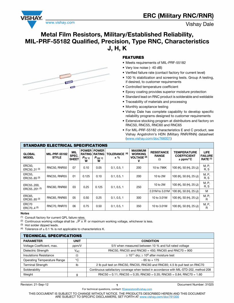
DIMENSIONS in inches (millimeters)
Note(1) Lead length for product in bulk pack. For product supplied in Tape and Reel, the actual lead length would be based on the body size, tape
spacing and lead trim.
POWER RATINGPower ratings are based on the following two conditions:1. ± 2.0 % maximum DR in 10 000 h load life2. + 175 °C maximum operating temperature
APPLICABLE MIL-SPECIFICATIONSMIL-PRF-55182:The ERC series meets the electrical, environmental anddimensional requirements of MIL-PRF-55182.
MIL-R-10509:MIL-PRF-55182 supercedes MIL-R-10509 on new designs.The ERC series meets or exceeds MIL-R-10509requirements.
DOCUMENTATION:Qualification and failure rate verification test data ismaintained by Vishay Dale and is available upon request.Lot traceability and identification data is maintained byVishay Dale for five years.
GLOBAL PART NUMBER INFORMATION
VISHAY DALEMODEL
MIL-PRF-55182STYLE A B C
(MAX.) D E
ERC50 RNC50,RNR50
0.150 ± 0.020(3.81 ± 0.51)
0.070 ± 0.010(1.78 ± 0.25)
0.187(4.75)
0.016 ± 0.002(0.41 ± 0.05)
1.25 ± 0.266(31.75 ± 6.76)
ERC55 RNC55,RNR55
0.250 + 0.031 - 0.046(6.35 + 0.79 - 1.17)
0.094 ± 0.012(2.39 ± 0.30)
0.300(7.62)
0.025 ± 0.002(0.64 ± 0.05)
1.50 ± 0.125(38.1 ± 3.18)
ERC55..200 RNC60,RNR60
0.280 ± 0.020(7.11 ± 0.51)
0.097 ± 0.012(2.46 ± 0.30)
0.350(8.89)
0.025 ± 0.002(0.64 ± 0.05)
1.50 ± 0.125(38.1 ± 3.18)
ERC65 RNC65,RNR65
0.562 ± 0.031(14.27 ± 0.79)
0.180 ± 0.015(4.57 ± 0.38)
0.687(17.45)
0.025 ± 0.002(0.64 ± 0.05)
1.50 ± 0.125(38.1 ± 3.18)
ERC70 RNC70,RNR70
0.562 ± 0.031(14.27 ± 0.79)
0.180 ± 0.015(4.57 ± 0.38)
0.687(17.45)
0.032 ± 0.002(0.81 ± 0.05)
1.50 ± 0.125(38.1 ± 3.18)
MIL STYLE RESISTANCE VALUE CODE
RNC = Solderable/ J = ± 25 ppm 3 digit significant B = ± 0.1 %D = ± 0.5 %F = ± 1 %
M = 1.0 %/1000 h B14 = Tin/lead, bulkBSL = Tin/lead, bulk,single lot date code
R36 = Tin/lead,T/R (full; 50, 55, 60)
R64 = Tin/lead,T/R (full; 65, 70)RE6 = Tin/lead,
T/R (1000 pieces)RSL = Tin/lead, T/R,single lot date code
weldable figure, followed P = 0.1 %/1000 h (Dash number)RNR = Solderable by a multiplier
Use “R” for values < 100 Ω
R = 0.01 %/1000 h (Up to 3 digits)only
10R0 = 10 Ω
S = 0.001 %/1000 h From 1 to 999
2152 = 21.5 k Ω
as applicable
3014 = 3.01 M Ω
New Global Part Numbering: RNC55H2152FRR36 (preferred part numbering format)
R N C 5 5 H 2 1 5 2 F R R 3 6
Historical Part Number example: RNC55H2152FR R36 (will continue to be accepted)
RNC55 H 2152 F R R36
MIL STYLE CHARACTERISTIC RESISTANCE VALUE TOLERANCE CODE FAILURE RATE PACKAGING
(see Standard Electrical
Specificationstable)
Blank = Standard
SPECIAL
4 = Hot solder dip (70’s)31= Hot solder dip (50’s)65 = Hot solder dip
(55’s, 65’s)201= Hot solder dip (60’s)
CHARACTERISTICS FAILURERATE
PACKAGING
K = ± 100 ppm H = ± 50 ppm
TOLERANCE
A
DB
E (1)
C(Max.)
MATERIAL SPECIFICATIONS
Element Vacuum-deposited nickel-chrome alloy
Core Fire-cleaned high purity ceramic
Encapsulation Specially formulated epoxy compound
TerminationStandard lead material is solder-coated copper solderable and weldable per MIL-STD-1276, type C
CAGE CODE: 91637
ERC (Military RNC/RNR)www.vishay.com Vishay Dale
Revision: 21-Sep-12 3 Document Number: 31025
For technical questions, contact: [email protected]
THIS DOCUMENT IS SUBJECT TO CHANGE WITHOUT NOTICE. THE PRODUCTS DESCRIBED HEREIN AND THIS DOCUMENTARE SUBJECT TO SPECIFIC DISCLAIMERS, SET FORTH AT www.vishay.com/doc?91000
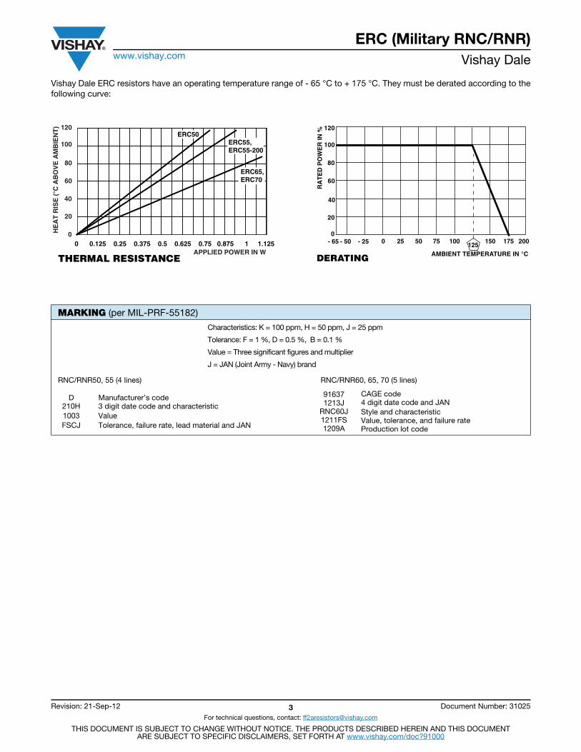
Vishay Dale ERC resistors have an operating temperature range of - 65 °C to + 175 °C. They must be derated according to thefollowing curve:
MARKING (per MIL-PRF-55182)
Characteristics: K = 100 ppm, H = 50 ppm, J = 25 ppm
Tolerance: F = 1 %, D = 0.5 %, B = 0.1 %
Value = Three significant figures and multiplier
J = JAN (Joint Army - Navy) brand
RNC/RNR50, 55 (4 lines) RNC/RNR60, 65, 70 (5 lines)
D210H1003FSCJ
Manufacturer’s code3 digit date code and characteristicValueTolerance, failure rate, lead material and JAN
916371213J
RNC60J1211FS 1209A
CAGE code4 digit date code and JANStyle and characteristicValue, tolerance, and failure rateProduction lot code
0 25 50 75 100 150 175 200125
AMBIENT TEMPERATURE IN °CDERATING
RA
TE
D P
OW
ER
IN %
0
20
40
60
80
100
120
- 65 - 50 - 250
20
40
60
80
100
120
APPLIED POWER IN W
HE
AT
RIS
E (
°C A
BO
VE
AM
BIE
NT
)
0 0.125 0.25 0.375 0.5 0.625 0.75 0.875 1 1.125
THERMAL RESISTANCE
ERC50ERC55,ERC55-200
ERC65,ERC70
Res
isto
rs -
Mili
tary
Res
isto
rs 1
01Resistive Products
military qualifications• Film Technology
– MIL-R-10509 Leaded Metal Film Resistor, type RN
– MIL-PRF-22684 Leaded Metal Film Resistor, type RL
– MIL-PRF-32159 Thick Film Chip Jumper, E-Rel type RCZ
– MIL-PRF-39017 Leaded Metal Film Resistor, E-Rel type RLR
– MIL-PRF-55182 Leaded Metal Film Resistor, E-Rel type RNC / RNR / RNN
– MIL-PRF-55342 Thick Film / Thin Film Chip Resistor, E-Rel type RM
• Wirewound Technology
– MIL-PRF-26 Leaded Wirewound Resistor, type RW
– MIL-PRF-18546 Housed Wirewound Resistor, type RE
– MIL-PRF-39007 Leaded Wirewound Resistor, E-Rel type RWR
– MIL-PRF-39009 Housed Wirewound Resistor, E-Rel type RER
– MIL-PRF-49465 Leaded Metal Element Resistor, type RLV
• Networks
– MIL-PRF-83401 Thick Film / Thin Film Resistor Network, type RZ
resources• For technical questions on Film and Network products, contact [email protected]
• For technical questions on Wirewound products contact [email protected]
THIs doCuMENT Is subJECT To CHaNgE WITHouT NoTICE. THE PRoduCTs dEsCRIbEd HEREIN aNd THIs doCuMENT aRE subJECT To sPECIFIC dIsCLaIMERs, sET FoRTH aT www.vishay.com/doc?91000
military resistors 101
INN
OVA
TI
ON AND TECHNO
LO
GY
1 9 6 2 - 2 0 1 2
V I s H ay I N T E R T E C H N o Lo gy, I N C .
VMN-sg2116-12051/22INsTRuCTIoNaL guIdE
Discrete Semiconductors and Passive ComponentsOne of the World’s Largest Manufacturers of
overview of military resistors from Vishay Dale
Res
isto
rs -
Mili
tary
Res
isto
rs 1
01Introduction
introductionVishay’s line of high-reliability products reflects a long-term commitment to our military customers. as one of the largest suppliers of military components, we continually strive to meet the changing application requirements of the defense, avionics and aerospace markets by developing new products and manufacturing technologies on an on going basis.
Vishay has one of the broadest lines of military-qualified resistors in the industry, and our high-reliability devices can be found in nearly every existing military program, including aircraft, satellites, missiles, weapons, ground vehicles, and ships.
Vishay is equipped to design and produce custom components to meet many design and reliability demands. In addition to standard military-grade resistor products, we also have many resistive products designed to meet various military source-controlled drawings.
Every component Vishay provides to the military, avionics and aerospace markets is backed by the comprehensive testing and failure analysis capabilities of our own technical staff, who are industry experts in understanding and meeting the requirements of the military environment. our technical expertise, our knowledge of the military industry, our broad product offering, and our ability to work long-term are all part of Vishay’s ongoing commitment to meeting the changing requirements of our most reliability-conscious customers, today and in the future.
target applications• aircraft
• avionics
• satellites
• surveillance
• Communications systems
• Naval vessels
• sonar
• Missile systems
• Weaponry
• Radar
• ground vehicles
• space, ocean, and deep earth exploration
• Medical instrumentation and medical implantables
THIs doCuMENT Is subJECT To CHaNgE WITHouT NoTICE. THE PRoduCTs dEsCRIbEd HEREIN aNd THIs doCuMENT aRE subJECT To sPECIFIC dIsCLaIMERs, sET FoRTH aT www.vishay.com/doc?91000
VMN-sg2116-12052/22INsTRuCTIoNaL guIdE
military resistors 101
INN
OVA
TI
ON AND TECHNO
LO
GY
1 9 6 2 - 2 0 1 2
V I s H ay I N T E R T E C H N o Lo gy, I N C .
Res
isto
rs -
Mili
tary
Res
isto
rs 1
01Product Information – Networks
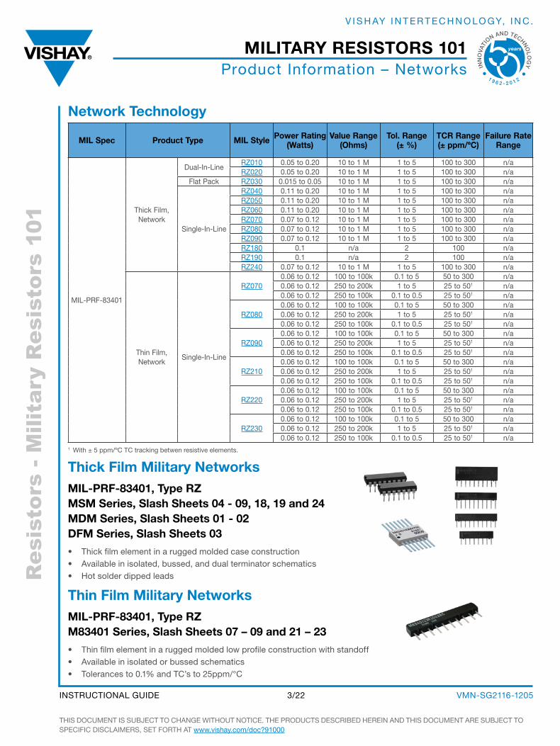
network technology
mil spec Product type mil style Power rating (Watts)
Value range (ohms)
tol. range (± %)
tcr range (± ppm/ºc)
failure rate range
MIL-PRF-83401
Thick Film, Network
dual-In-Line RZ010 0.05 to 0.20 10 to 1 M 1 to 5 100 to 300 n/a RZ020 0.05 to 0.20 10 to 1 M 1 to 5 100 to 300 n/a
Flat Pack RZ030 0.015 to 0.05 10 to 1 M 1 to 5 100 to 300 n/a
single-In-Line
RZ040 0.11 to 0.20 10 to 1 M 1 to 5 100 to 300 n/a RZ050 0.11 to 0.20 10 to 1 M 1 to 5 100 to 300 n/a RZ060 0.11 to 0.20 10 to 1 M 1 to 5 100 to 300 n/a RZ070 0.07 to 0.12 10 to 1 M 1 to 5 100 to 300 n/a RZ080 0.07 to 0.12 10 to 1 M 1 to 5 100 to 300 n/a RZ090 0.07 to 0.12 10 to 1 M 1 to 5 100 to 300 n/a RZ180 0.1 n/a 2 100 n/a RZ190 0.1 n/a 2 100 n/a RZ240 0.07 to 0.12 10 to 1 M 1 to 5 100 to 300 n/a
Thin Film, Network
single-In-Line
RZ0700.06 to 0.12 100 to 100k 0.1 to 5 50 to 300 n/a0.06 to 0.12 250 to 200k 1 to 5 25 to 501 n/a0.06 to 0.12 250 to 100k 0.1 to 0.5 25 to 501 n/a
RZ0800.06 to 0.12 100 to 100k 0.1 to 5 50 to 300 n/a0.06 to 0.12 250 to 200k 1 to 5 25 to 501 n/a0.06 to 0.12 250 to 100k 0.1 to 0.5 25 to 501 n/a
RZ0900.06 to 0.12 100 to 100k 0.1 to 5 50 to 300 n/a0.06 to 0.12 250 to 200k 1 to 5 25 to 501 n/a0.06 to 0.12 250 to 100k 0.1 to 0.5 25 to 501 n/a
RZ2100.06 to 0.12 100 to 100k 0.1 to 5 50 to 300 n/a0.06 to 0.12 250 to 200k 1 to 5 25 to 501 n/a0.06 to 0.12 250 to 100k 0.1 to 0.5 25 to 501 n/a
RZ2200.06 to 0.12 100 to 100k 0.1 to 5 50 to 300 n/a0.06 to 0.12 250 to 200k 1 to 5 25 to 501 n/a0.06 to 0.12 250 to 100k 0.1 to 0.5 25 to 501 n/a
RZ2300.06 to 0.12 100 to 100k 0.1 to 5 50 to 300 n/a0.06 to 0.12 250 to 200k 1 to 5 25 to 501 n/a0.06 to 0.12 250 to 100k 0.1 to 0.5 25 to 501 n/a
1 With ± 5 ppm/ºC TC tracking betwen resistive elements.
thick film military networksmil-Prf-83401, type rZ msm series, slash sheets 04 - 09, 18, 19 and 24 mDm series, slash sheets 01 - 02 Dfm series, slash sheets 03
• Thick film element in a rugged molded case construction• available in isolated, bussed, and dual terminator schematics• Hot solder dipped leads
THIs doCuMENT Is subJECT To CHaNgE WITHouT NoTICE. THE PRoduCTs dEsCRIbEd HEREIN aNd THIs doCuMENT aRE subJECT To sPECIFIC dIsCLaIMERs, sET FoRTH aT www.vishay.com/doc?91000
VMN-sg2116-12053/22INsTRuCTIoNaL guIdE
military resistors 101
INN
OVA
TI
ON AND TECHNO
LO
GY
1 9 6 2 - 2 0 1 2
V I s H ay I N T E R T E C H N o Lo gy, I N C .
thin film military networksmil-Prf-83401, type rZ m83401 series, slash sheets 07 – 09 and 21 – 23
• Thin film element in a rugged molded low profile construction with standoff• available in isolated or bussed schematics• Tolerances to 0.1% and TC’s to 25ppm/°C
Res
isto
rs -
Mili
tary
Res
isto
rs 1
01Product Information – Networks
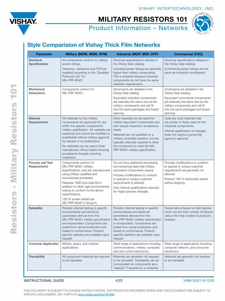
style comparision of Vishay thick film networksParameter military (mDm, msm, Dfm) industrial (mDP, msP, DfP) commercial (csc)
electrical specifications
all components conform to military power ratings.
Tolerance, resistance and TCR are supplied according to the “Qualified Products List” for MIL-PRF-83401.
Electrical specifications detailed in the Vishay dale catalog.
Industrial power ratings are generally higher than military components. This is possible because industrial components do not have the same reliability requirements.
Electrical specifications detailed in the Vishay dale catalog.
Commercial power ratings are the same as industrial counterparts.
mechanical Dimensions
Components conform to MIL-PRF-83401.
dimensions are detailed in the Vishay dale catalog.
Equivalent industrial components are basically the same size as the military components and will fit into the same packages and board spacing.
dimensions are detailed in the Vishay dale catalog.
Equivalent commercial components are basically the same size as the military components and will fit into the same packages and board spacing.
material requirements
all materials for the military components are approved for use within the specific components’ military qualification. all materials are baselined and cannot be modified or substituted without military approval, by request or re-qualification.
No materials can be used in their manufacture without labels showing acceptance through incoming inspection.
Most materials are the same for military equivalent components and also require inspection acceptance labels.
Materials are not qualified on a military controlled baseline, but are typically internally required to allow the component to meet the MIL-PRF-83401 military specification.
uses low cost materials that are similar to those used for the Industrial components.
Internal qualification of changes does not require a governing agency’s approval.
Process and test requirements
Components conform to MIL-PRF-83401 military specifications, and are manufactured using military qualified and documented processes.
Requires 1000 hour load life in addition to other rigid environmental testing to conform to the above specifications.
100 % screen tested per MIL-PRF-83401’s group a.
do not have additional processing and screening tests that military equivalent components require.
Process modifications to conform to special or unique customer requirements is allowed.
only internal qualifications required for major process changes.
Process modifications to conform to special or unique customer requirements are generally not allowed.
Product 100 % electrically tested before shipping.
reliability Periodic internal testing to specific environmental and electrical parameters derived from the MIL-PRF-83401 military specification are incorporated. Components are pulled from actual production and tested to conformance. Product specific statistics are available upon request.
Periodic internal testing to specific environmental and electrical parameters derived from the MIL-PRF-83401 military specification is incorporated. Components are pulled from actual production and tested to conformance. Product specific statistics are available upon request.
Failure rate is based on field failures, which are the total number of failures versus the total number of products shipped.
customer application Military, space, and medical applications.
Wide range of applications including communications, military, computer, test and control electronics.
Wide range of applications including computer, telecom, and consumer electronics.
traceability all component materials are required to be traceable.
Materials are generally not required to be traceable. Traceability can be incorporated on components as a “special” if required by a customer.
Materials are generally not required to be traceable.
THIs doCuMENT Is subJECT To CHaNgE WITHouT NoTICE. THE PRoduCTs dEsCRIbEd HEREIN aNd THIs doCuMENT aRE subJECT To sPECIFIC dIsCLaIMERs, sET FoRTH aT www.vishay.com/doc?91000
VMN-sg2116-12054/22INsTRuCTIoNaL guIdE
military resistors 101
INN
OVA
TI
ON AND TECHNO
LO
GY
1 9 6 2 - 2 0 1 2
V I s H ay I N T E R T E C H N o Lo gy, I N C .
Res
isto
rs -
Mili
tary
Res
isto
rs 1
01Product Information – Film axial Leaded
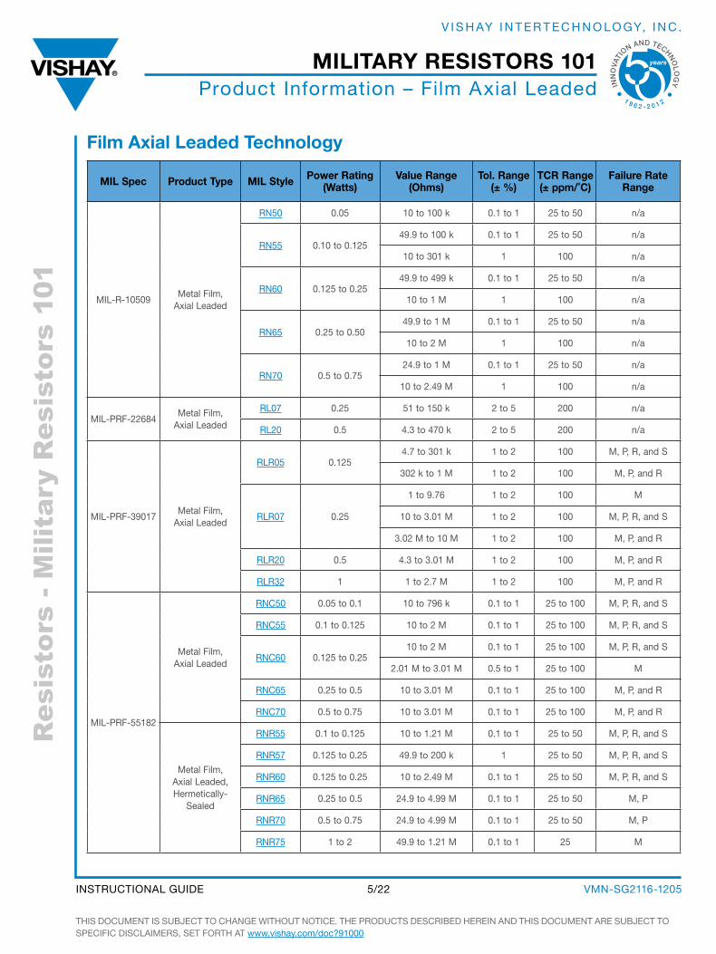
film axial leaded technology
mil spec Product type mil style Power rating (Watts)
Value range (ohms)
tol. range (± %)
tcr range (± ppm/˚c)
failure rate range
MIL-R-10509 Metal Film,
axial Leaded
RN50 0.05 10 to 100 k 0.1 to 1 25 to 50 n/a
RN55 0.10 to 0.125 49.9 to 100 k 0.1 to 1 25 to 50 n/a
10 to 301 k 1 100 n/a
RN60 0.125 to 0.25 49.9 to 499 k 0.1 to 1 25 to 50 n/a
10 to 1 M 1 100 n/a
RN65 0.25 to 0.50 49.9 to 1 M 0.1 to 1 25 to 50 n/a
10 to 2 M 1 100 n/a
RN70 0.5 to 0.7524.9 to 1 M 0.1 to 1 25 to 50 n/a
10 to 2.49 M 1 100 n/a
MIL-PRF-22684 Metal Film,
axial Leaded
RL07 0.25 51 to 150 k 2 to 5 200 n/a
RL20 0.5 4.3 to 470 k 2 to 5 200 n/a
MIL-PRF-39017 Metal Film,
axial Leaded
RLR05 0.1254.7 to 301 k 1 to 2 100 M, P, R, and s
302 k to 1 M 1 to 2 100 M, P, and R
RLR07 0.25
1 to 9.76 1 to 2 100 M
10 to 3.01 M 1 to 2 100 M, P, R, and s
3.02 M to 10 M 1 to 2 100 M, P, and R
RLR20 0.5 4.3 to 3.01 M 1 to 2 100 M, P, and R
RLR32 1 1 to 2.7 M 1 to 2 100 M, P, and R
MIL-PRF-55182
Metal Film, axial Leaded
RNC50 0.05 to 0.1 10 to 796 k 0.1 to 1 25 to 100 M, P, R, and s
RNC55 0.1 to 0.125 10 to 2 M 0.1 to 1 25 to 100 M, P, R, and s
RNC60 0.125 to 0.2510 to 2 M 0.1 to 1 25 to 100 M, P, R, and s
2.01 M to 3.01 M 0.5 to 1 25 to 100 M
RNC65 0.25 to 0.5 10 to 3.01 M 0.1 to 1 25 to 100 M, P, and R
RNC70 0.5 to 0.75 10 to 3.01 M 0.1 to 1 25 to 100 M, P, and R
Metal Film, axial Leaded, Hermetically-
sealed
RNR55 0.1 to 0.125 10 to 1.21 M 0.1 to 1 25 to 50 M, P, R, and s
RNR57 0.125 to 0.25 49.9 to 200 k 1 25 to 50 M, P, R, and s
RNR60 0.125 to 0.25 10 to 2.49 M 0.1 to 1 25 to 50 M, P, R, and s
RNR65 0.25 to 0.5 24.9 to 4.99 M 0.1 to 1 25 to 50 M, P
RNR70 0.5 to 0.75 24.9 to 4.99 M 0.1 to 1 25 to 50 M, P
RNR75 1 to 2 49.9 to 1.21 M 0.1 to 1 25 M
THIs doCuMENT Is subJECT To CHaNgE WITHouT NoTICE. THE PRoduCTs dEsCRIbEd HEREIN aNd THIs doCuMENT aRE subJECT To sPECIFIC dIsCLaIMERs, sET FoRTH aT www.vishay.com/doc?91000
VMN-sg2116-12055/22INsTRuCTIoNaL guIdE
military resistors 101
INN
OVA
TI
ON AND TECHNO
LO
GY
1 9 6 2 - 2 0 1 2
V I s H ay I N T E R T E C H N o Lo gy, I N C .
Res
isto
rs -
Mili
tary
Res
isto
rs 1
01Product Information – Film axial Leaded
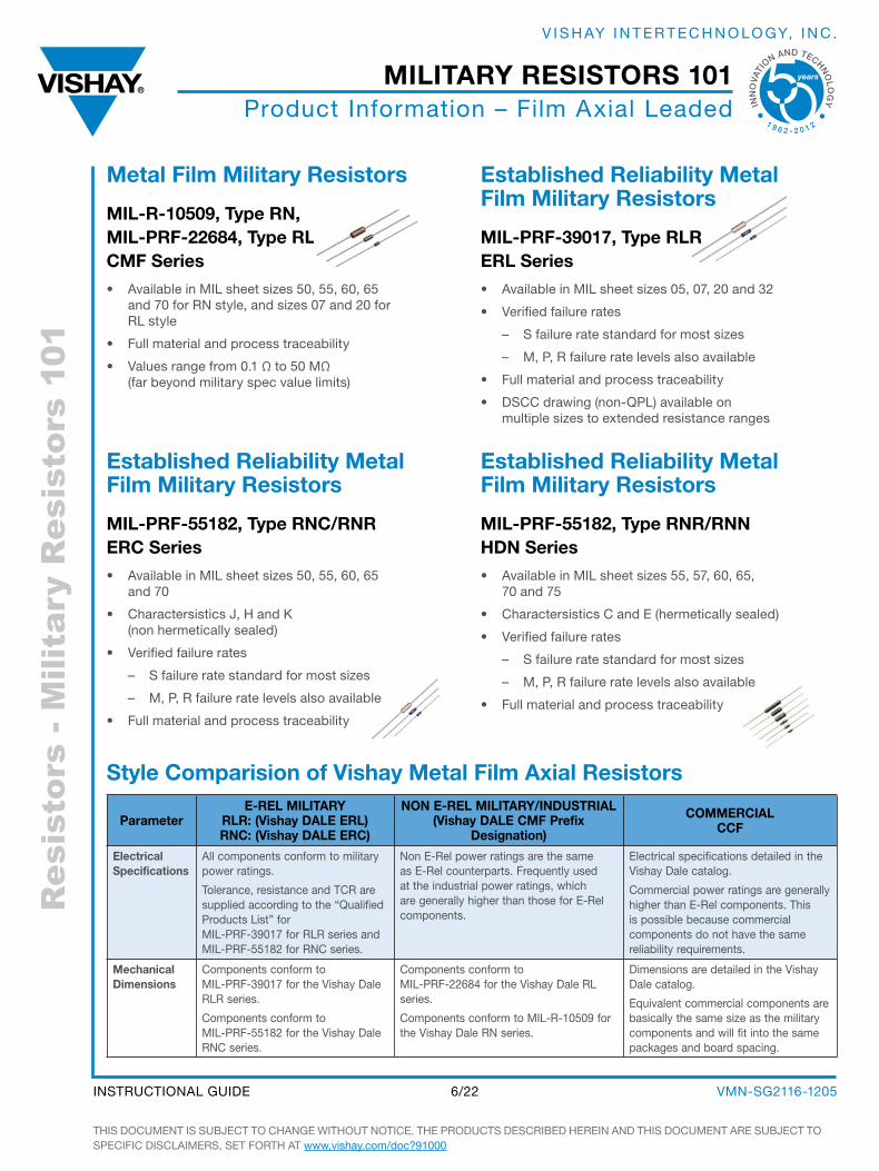
metal film military resistors
mil-r-10509, type rn, mil-Prf-22684, type rl cmf series
• available in MIL sheet sizes 50, 55, 60, 65 and 70 for RN style, and sizes 07 and 20 for RL style
• Full material and process traceability
• Values range from 0.1 Ω to 50 MΩ (far beyond military spec value limits)
established reliability metal film military resistors
mil-Prf-39017, type rlr erl series
• available in MIL sheet sizes 05, 07, 20 and 32
• Verified failure rates
– s failure rate standard for most sizes
– M, P, R failure rate levels also available
• Full material and process traceability
• dsCC drawing (non-QPL) available on multiple sizes to extended resistance ranges
established reliability metal film military resistors
mil-Prf-55182, type rnc/rnr erc series
• available in MIL sheet sizes 50, 55, 60, 65 and 70
• Charactersistics J, H and K (non hermetically sealed)
• Verified failure rates
– s failure rate standard for most sizes
– M, P, R failure rate levels also available
• Full material and process traceability
established reliability metal film military resistors
mil-Prf-55182, type rnr/rnn HDn series
• available in MIL sheet sizes 55, 57, 60, 65, 70 and 75
• Charactersistics C and E (hermetically sealed)
• Verified failure rates
– s failure rate standard for most sizes
– M, P, R failure rate levels also available
• Full material and process traceability
style comparision of Vishay metal film axial resistors
Parametere-rel military
rlr: (Vishay Dale erl)rnc: (Vishay Dale erc)
non e-rel military/inDustrial(Vishay Dale cmf Prefix
Designation)
commercialccf
electrical specifications
all components conform to military power ratings.
Tolerance, resistance and TCR are supplied according to the “Qualified Products List” for MIL-PRF-39017 for RLR series and MIL-PRF-55182 for RNC series.
Non E-Rel power ratings are the same as E-Rel counterparts. Frequently used at the industrial power ratings, which are generally higher than those for E-Rel components.
Electrical specifications detailed in the Vishay dale catalog.
Commercial power ratings are generally higher than E-Rel components. This is possible because commercial components do not have the same reliability requirements.
mechanical Dimensions
Components conform to MIL-PRF-39017 for the Vishay dale RLR series.
Components conform to MIL-PRF-55182 for the Vishay dale RNC series.
Components conform to MIL-PRF-22684 for the Vishay dale RL series.
Components conform to MIL-R-10509 for the Vishay dale RN series.
dimensions are detailed in the Vishay dale catalog.
Equivalent commercial components are basically the same size as the military components and will fit into the same packages and board spacing.
THIs doCuMENT Is subJECT To CHaNgE WITHouT NoTICE. THE PRoduCTs dEsCRIbEd HEREIN aNd THIs doCuMENT aRE subJECT To sPECIFIC dIsCLaIMERs, sET FoRTH aT www.vishay.com/doc?91000
VMN-sg2116-12056/22INsTRuCTIoNaL guIdE
military resistors 101
INN
OVA
TI
ON AND TECHNO
LO
GY
1 9 6 2 - 2 0 1 2
V I s H ay I N T E R T E C H N o Lo gy, I N C .
Res
isto
rs -
Mili
tary
Res
isto
rs 1
01Product Information – Film axial Leaded
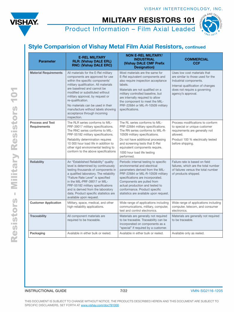
style comparision of Vishay metal film axial resistors, continued
Parametere-rel military
rlr: (Vishay Dale erl)rnc: (Vishay Dale erc)
non e-rel military/inDustrial
(Vishay Dale cmf Prefix Designation)
commercialccf
material requirements all materials for the E-Rel military components are approved for use within the specific components’ military qualification. all materials are baselined and cannot be modified or substituted without military approval, by request or re-qualification.
No materials can be used in their manufacture without labels showing acceptance through incoming inspection.
Most materials are the same for E-Rel equivalent components and also require inspection acceptance labels.
Materials are not qualified on a military controlled baseline, but are internally required to allow the component to meet the MIL-PRF-22684 or MlL-R-10509 military specifications.
uses low cost materials that are similar to those used for the Industrial components.
Internal qualification of changes does not require a governing agency’s approval.
Process and test requirements
The RLR series conforms to MIL-PRF-39017 military specifications. The RNC series conforms to MIL-PRF-55182 military specifications.
Reliability determination requires 10 000 hour load life in addition to other rigid environmental testing to conform to the above specifications
The RL series conforms to MIL-PRF-22684 military specifications. The RN series conforms to MIL-R-10509 military specifications.
do not have additional processing and screening tests that E-Rel equivalent components require.
1000 hour load life testing performed.
Process modifications to conform to special or unique customer requirements are generally not allowed.
Product 100 % electrically tested before shipping.
reliability an “Established Reliability” quality level is determined by continuously testing thousands of components in a qualified laboratory. The reliability “Failure Rate Level” is specified in the MIL-PRF-39017 or MIL-PRF-55182 military specifications and is derived from the laboratory data. Product specific statistics are available upon request.
Periodic internal testing to specific environmental and electrical parameters derived from the MIL-PRF-22684 or MIL-R-10509 military specifications are incorporated. Components are pulled from actual production and tested to conformance. Product specific statistics are available upon request.
Failure rate is based on field failures, which are the total number of failures versus the total number of products shipped.
customer application Military, space, medical, and other high-reliability applications.
Wide range of applications including communications, military, computer, test and control electronics.
Wide range of applications including computer, telecom, and consumer electronics.
traceability all component materials are required to be traceable.
Materials are generally not required to be traceable. Traceability can be incorporated on components as a “special” if required by a customer.
Materials are generally not required to be traceable.
Packaging available in either bulk or reeled. available in either bulk or reeled. available only as reeled.
THIs doCuMENT Is subJECT To CHaNgE WITHouT NoTICE. THE PRoduCTs dEsCRIbEd HEREIN aNd THIs doCuMENT aRE subJECT To sPECIFIC dIsCLaIMERs, sET FoRTH aT www.vishay.com/doc?91000
VMN-sg2116-12057/22INsTRuCTIoNaL guIdE
military resistors 101
INN
OVA
TI
ON AND TECHNO
LO
GY
1 9 6 2 - 2 0 1 2
V I s H ay I N T E R T E C H N o Lo gy, I N C .
Res
isto
rs -
Mili
tary
Res
isto
rs 1
01Product Information – Film surface Mount
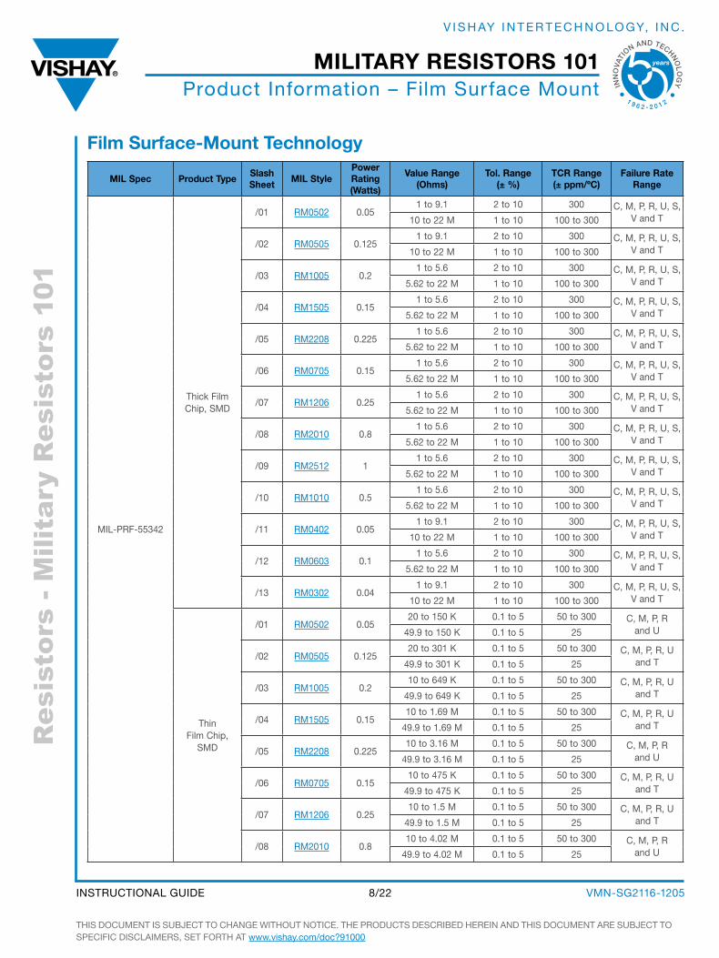
film surface-mount technology
mil spec Product type slash sheet mil style
Power rating (Watts)
Value range (ohms)
tol. range (± %)
tcr range (± ppm/ºc)
failure rate range
MIL-PRF-55342
Thick Film Chip, sMd
/01 RM0502 0.051 to 9.1 2 to 10 300 C, M, P, R, u, s,
V and T10 to 22 M 1 to 10 100 to 300
/02 RM0505 0.1251 to 9.1 2 to 10 300 C, M, P, R, u, s,
V and T10 to 22 M 1 to 10 100 to 300
/03 RM1005 0.21 to 5.6 2 to 10 300 C, M, P, R, u, s,
V and T5.62 to 22 M 1 to 10 100 to 300
/04 RM1505 0.151 to 5.6 2 to 10 300 C, M, P, R, u, s,
V and T5.62 to 22 M 1 to 10 100 to 300
/05 RM2208 0.2251 to 5.6 2 to 10 300 C, M, P, R, u, s,
V and T5.62 to 22 M 1 to 10 100 to 300
/06 RM0705 0.151 to 5.6 2 to 10 300 C, M, P, R, u, s,
V and T5.62 to 22 M 1 to 10 100 to 300
/07 RM1206 0.251 to 5.6 2 to 10 300 C, M, P, R, u, s,
V and T5.62 to 22 M 1 to 10 100 to 300
/08 RM2010 0.81 to 5.6 2 to 10 300 C, M, P, R, u, s,
V and T5.62 to 22 M 1 to 10 100 to 300
/09 RM2512 11 to 5.6 2 to 10 300 C, M, P, R, u, s,
V and T5.62 to 22 M 1 to 10 100 to 300
/10 RM1010 0.51 to 5.6 2 to 10 300 C, M, P, R, u, s,
V and T5.62 to 22 M 1 to 10 100 to 300
/11 RM0402 0.051 to 9.1 2 to 10 300 C, M, P, R, u, s,
V and T10 to 22 M 1 to 10 100 to 300
/12 RM0603 0.11 to 5.6 2 to 10 300 C, M, P, R, u, s,
V and T5.62 to 22 M 1 to 10 100 to 300
/13 RM0302 0.041 to 9.1 2 to 10 300 C, M, P, R, u, s,
V and T10 to 22 M 1 to 10 100 to 300
Thin Film Chip,
sMd
/01 RM0502 0.0520 to 150 K 0.1 to 5 50 to 300 C, M, P, R
and u49.9 to 150 K 0.1 to 5 25
/02 RM0505 0.12520 to 301 K 0.1 to 5 50 to 300 C, M, P, R, u
and T49.9 to 301 K 0.1 to 5 25
/03 RM1005 0.210 to 649 K 0.1 to 5 50 to 300 C, M, P, R, u
and T49.9 to 649 K 0.1 to 5 25
/04 RM1505 0.1510 to 1.69 M 0.1 to 5 50 to 300 C, M, P, R, u
and T49.9 to 1.69 M 0.1 to 5 25
/05 RM2208 0.22510 to 3.16 M 0.1 to 5 50 to 300 C, M, P, R
and u49.9 to 3.16 M 0.1 to 5 25
/06 RM0705 0.1510 to 475 K 0.1 to 5 50 to 300 C, M, P, R, u
and T49.9 to 475 K 0.1 to 5 25
/07 RM1206 0.2510 to 1.5 M 0.1 to 5 50 to 300 C, M, P, R, u
and T49.9 to 1.5 M 0.1 to 5 25
/08 RM2010 0.810 to 4.02 M 0.1 to 5 50 to 300 C, M, P, R
and u49.9 to 4.02 M 0.1 to 5 25
THIs doCuMENT Is subJECT To CHaNgE WITHouT NoTICE. THE PRoduCTs dEsCRIbEd HEREIN aNd THIs doCuMENT aRE subJECT To sPECIFIC dIsCLaIMERs, sET FoRTH aT www.vishay.com/doc?91000
VMN-sg2116-12058/22INsTRuCTIoNaL guIdE
military resistors 101
INN
OVA
TI
ON AND TECHNO
LO
GY
1 9 6 2 - 2 0 1 2
V I s H ay I N T E R T E C H N o Lo gy, I N C .
Res
isto
rs -
Mili
tary
Res
isto
rs 1
01Product Information – Film surface Mount
mil spec Product type
slash sheet mil style
Power rating (Watts)
Value range (ohms)
tol. range (± %)
tcr range (± ppm/ºc)
failure rate range
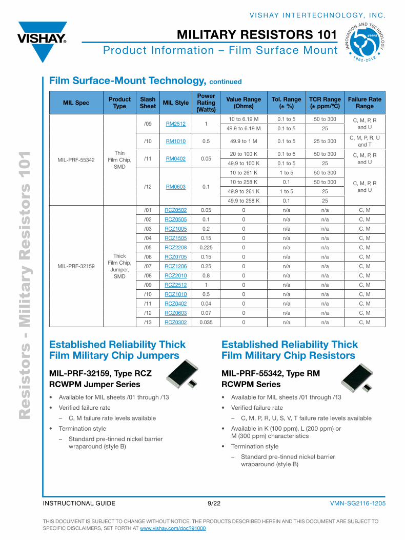
MIL-PRF-55342Thin
Film Chip, sMd
/09 RM2512 110 to 6.19 M 0.1 to 5 50 to 300 C, M, P, R
and u49.9 to 6.19 M 0.1 to 5 25
/10 RM1010 0.5 49.9 to 1 M 0.1 to 5 25 to 300C, M, P, R, u
and T
/11 RM0402 0.0520 to 100 K 0.1 to 5 50 to 300 C, M, P, R
and u49.9 to 100 K 0.1 to 5 25
/12 RM0603 0.1
10 to 261 K 1 to 5 50 to 300
C, M, P, R and u
10 to 258 K 0.1 50 to 300
49.9 to 261 K 1 to 5 25
49.9 to 258 K 0.1 25
MIL-PRF-32159
Thick Film Chip, Jumper,
sMd
/01 RCZ0502 0.05 0 n/a n/a C, M
/02 RCZ0505 0.1 0 n/a n/a C, M
/03 RCZ1005 0.2 0 n/a n/a C, M
/04 RCZ1505 0.15 0 n/a n/a C, M
/05 RCZ2208 0.225 0 n/a n/a C, M
/06 RCZ0705 0.15 0 n/a n/a C, M
/07 RCZ1206 0.25 0 n/a n/a C, M
/08 RCZ2010 0.8 0 n/a n/a C, M
/09 RCZ2512 1 0 n/a n/a C, M
/10 RCZ1010 0.5 0 n/a n/a C, M
/11 RCZ0402 0.04 0 n/a n/a C, M
/12 RCZ0603 0.07 0 n/a n/a C, M
/13 RCZ0302 0.035 0 n/a n/a C, M
established reliability thick film military chip Jumpers
mil-Prf-32159, type rcZ rcWPm Jumper series
• available for MIL sheets /01 through /13
• Verified failure rate
– C, M failure rate levels available
• Termination style
– standard pre-tinned nickel barrier wraparound (style b)
established reliability thick film military chip resistors
mil-Prf-55342, type rm rcWPm series
• available for MIL sheets /01 through /13
• Verified failure rate
– C, M, P, R, u, s, V, T failure rate levels available
• available in K (100 ppm), L (200 ppm) or M (300 ppm) characteristics
• Termination style
– standard pre-tinned nickel barrier wraparound (style b)
film surface-mount technology, continued
THIs doCuMENT Is subJECT To CHaNgE WITHouT NoTICE. THE PRoduCTs dEsCRIbEd HEREIN aNd THIs doCuMENT aRE subJECT To sPECIFIC dIsCLaIMERs, sET FoRTH aT www.vishay.com/doc?91000
VMN-sg2116-12059/22INsTRuCTIoNaL guIdE
military resistors 101
INN
OVA
TI
ON AND TECHNO
LO
GY
1 9 6 2 - 2 0 1 2
V I s H ay I N T E R T E C H N o Lo gy, I N C .
Res
isto
rs -
Mili
tary
Res
isto
rs 1
01Product Information – Film surface Mount
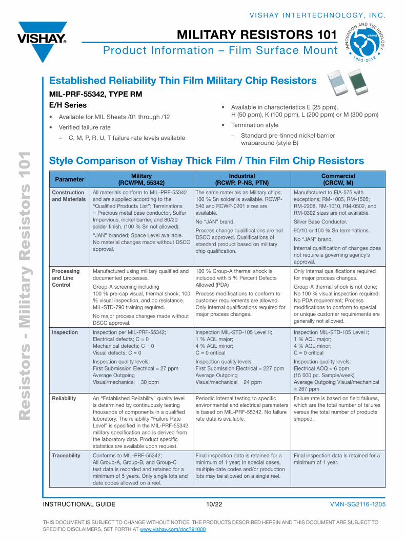
established reliability thin film military chip resistorsmil-Prf-55342, tyPe rm e/H series
• available for MIL sheets /01 through /12
• Verified failure rate
– C, M, P, R, u, T failure rate levels available
• available in characteristics E (25 ppm), H (50 ppm), K (100 ppm), L (200 ppm) or M (300 ppm)
• Termination style
– standard pre-tinned nickel barrier wraparound (style b)
style comparison of Vishay thick film / thin film chip resistors
Parameter military (rcWPm, 55342)
industrial (rcWP, P-ns, Ptn)
commercial (crcW, m)
construction and materials
all materials conform to MIL-PRF-55342 and are supplied according to the “Qualified Products List”; Terminations = Precious metal base conductor, sulfur Impervious, nickel barrier, and 80/20 solder finish. (100 % sn not allowed).
“JaN” branded; space Level available. No material changes made without dsCC approval.
The same materials as Military chips; 100 % sn solder is available. RCWP-540 and RCWP-0201 sizes are available.
No “JaN” brand.
Process change qualifications are not dsCC approved. Qualifications of standard product based on military chip qualification.
Manufactured to EIa-575 with exceptions; RM-1005, RM-1505; RM-2208, RM-1010, RM-0502, and RM-0302 sizes are not available.
silver base Conductor.
90/10 or 100 % sn terminations.
No “JaN” brand.
Internal qualification of changes does not require a governing agency’s approval.
Processing and line control
Manufactured using military qualified and documented processes.
group-a screening including 100 % pre-cap visual, thermal shock, 100 % visual inspection, and dc resistance. MIL-sTd-790 training required.
No major process changes made without dsCC approval.
100 % group-a thermal shock is included with 5 % Percent defects allowed (Pda)
Process modifications to conform to customer requirements are allowed. only internal qualifications required for major process changes.
only internal qualifications required for major process changes.
group-a thermal shock is not done; No 100 % visual inspection required; No Pda requirement; Process modifications to conform to special or unique customer requirements are generally not allowed.
inspection Inspection per MIL-PRF-55342; Electrical defects; C = 0 Mechanical defects; C = 0 Visual defects; C = 0
Inspection quality levels: First submission Electrical = 27 ppm average outgoing Visual/mechanical = 30 ppm
Inspection MIL-sTd-105 Level II; 1 % aQL major; 4 % aQL minor; C = 0 critical
Inspection quality levels: First submission Electrical = 227 ppm average outgoing Visual/mechanical = 24 ppm
Inspection MIL-sTd-105 Level I; 1 % aQL major; 4 % aQL minor; C = 0 critical
Inspection quality levels: Electrical aoQ = 6 ppm (15 000 pc. sample/week) average outgoing Visual/mechanical = 267 ppm
reliability an “Established Reliability” quality level is determined by continuously testing thousands of components in a qualified laboratory. The reliability “Failure Rate Level” is specified in the MIL-PRF-55342 military specification and is derived from the laboratory data. Product specific statistics are available upon request.
Periodic internal testing to specific environmental and electrical parameters is based on MIL-PRF-55342. No failure rate data is available.
Failure rate is based on field failures, which are the total number of failures versus the total number of products shipped.
traceability Conforms to MIL-PRF-55342; all group-a, group-b, and group-C test data is recorded and retained for a minimum of 5 years. only single lots and date codes allowed on a reel.
Final inspection data is retained for a minimum of 1 year; In special cases, multiple date codes and/or production lots may be allowed on a single reel.
Final inspection data is retained for a minimum of 1 year.
THIs doCuMENT Is subJECT To CHaNgE WITHouT NoTICE. THE PRoduCTs dEsCRIbEd HEREIN aNd THIs doCuMENT aRE subJECT To sPECIFIC dIsCLaIMERs, sET FoRTH aT www.vishay.com/doc?91000
VMN-sg2116-120510/22INsTRuCTIoNaL guIdE
military resistors 101
INN
OVA
TI
ON AND TECHNO
LO
GY
1 9 6 2 - 2 0 1 2
V I s H ay I N T E R T E C H N o Lo gy, I N C .
Res
isto
rs -
Mili
tary
Res
isto
rs 1
01Product Information –
Wirewound/Metal Element axial Leaded
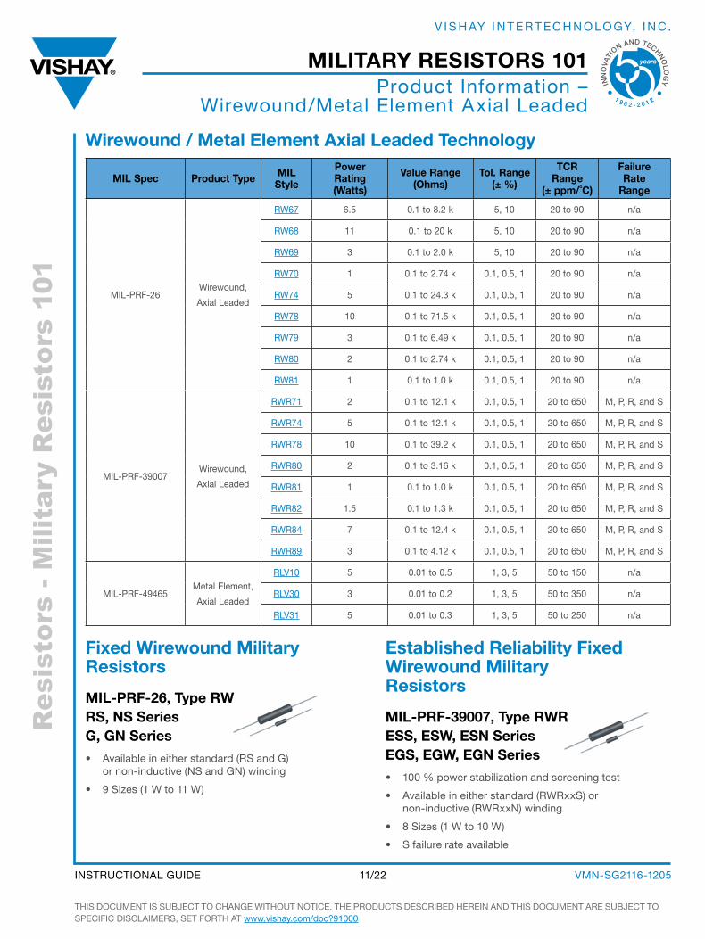
Wirewound / metal element axial leaded technology
mil spec Product type milstyle
Powerrating(Watts)
Value range(ohms)
tol. range (± %)
tcr range
(± ppm/˚c)
failurerate
range
MIL-PRF-26Wirewound,
axial Leaded
RW67 6.5 0.1 to 8.2 k 5, 10 20 to 90 n/a
RW68 11 0.1 to 20 k 5, 10 20 to 90 n/a
RW69 3 0.1 to 2.0 k 5, 10 20 to 90 n/a
RW70 1 0.1 to 2.74 k 0.1, 0.5, 1 20 to 90 n/a
RW74 5 0.1 to 24.3 k 0.1, 0.5, 1 20 to 90 n/a
RW78 10 0.1 to 71.5 k 0.1, 0.5, 1 20 to 90 n/a
RW79 3 0.1 to 6.49 k 0.1, 0.5, 1 20 to 90 n/a
RW80 2 0.1 to 2.74 k 0.1, 0.5, 1 20 to 90 n/a
RW81 1 0.1 to 1.0 k 0.1, 0.5, 1 20 to 90 n/a
MIL-PRF-39007Wirewound,
axial Leaded
RWR71 2 0.1 to 12.1 k 0.1, 0.5, 1 20 to 650 M, P, R, and s
RWR74 5 0.1 to 12.1 k 0.1, 0.5, 1 20 to 650 M, P, R, and s
RWR78 10 0.1 to 39.2 k 0.1, 0.5, 1 20 to 650 M, P, R, and s
RWR80 2 0.1 to 3.16 k 0.1, 0.5, 1 20 to 650 M, P, R, and s
RWR81 1 0.1 to 1.0 k 0.1, 0.5, 1 20 to 650 M, P, R, and s
RWR82 1.5 0.1 to 1.3 k 0.1, 0.5, 1 20 to 650 M, P, R, and s
RWR84 7 0.1 to 12.4 k 0.1, 0.5, 1 20 to 650 M, P, R, and s
RWR89 3 0.1 to 4.12 k 0.1, 0.5, 1 20 to 650 M, P, R, and s
MIL-PRF-49465Metal Element,
axial Leaded
RLV10 5 0.01 to 0.5 1, 3, 5 50 to 150 n/a
RLV30 3 0.01 to 0.2 1, 3, 5 50 to 350 n/a
RLV31 5 0.01 to 0.3 1, 3, 5 50 to 250 n/a
fixed Wirewound military resistors
mil-Prf-26, type rW rs, ns series G, Gn series
• available in either standard (Rs and g) or non-inductive (Ns and gN) winding
• 9 sizes (1 W to 11 W)
established reliability fixed Wirewound military resistors
mil-Prf-39007, type rWr ess, esW, esn series eGs, eGW, eGn series
• 100 % power stabilization and screening test
• available in either standard (RWRxxs) or non-inductive (RWRxxN) winding
• 8 sizes (1 W to 10 W)
• s failure rate available
THIs doCuMENT Is subJECT To CHaNgE WITHouT NoTICE. THE PRoduCTs dEsCRIbEd HEREIN aNd THIs doCuMENT aRE subJECT To sPECIFIC dIsCLaIMERs, sET FoRTH aT www.vishay.com/doc?91000
VMN-sg2116-120511/22INsTRuCTIoNaL guIdE
military resistors 101
INN
OVA
TI
ON AND TECHNO
LO
GY
1 9 6 2 - 2 0 1 2
V I s H ay I N T E R T E C H N o Lo gy, I N C .
Res
isto
rs -
Mili
tary
Res
isto
rs 1
01
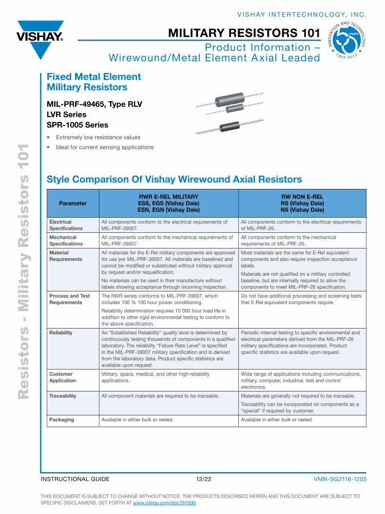
fixed metal element military resistors
mil-Prf-49465, type rlV lVr series sPr-1005 series
• Extremely low resistance values
• Ideal for current sensing applications
style comparison of Vishay Wirewound axial resistors
ParameterrWr e-rel military ess, eGs (Vishay Dale) esn, eGn (Vishay Dale)
rW non e-rel rs (Vishay Dale) ns (Vishay Dale)
electrical specifications
all components conform to the electrical requirements of MIL-PRF-39007.
all components conform to the electrical requirements of MIL-PRF-26.
mechanical specifications
all components conform to the mechanical requirements of MIL-PRF-39007.
all components conform to the mechanical requirements of MIL-PRF-26.
material requirements
all materials for the E-Rel military components are approved for use per MIL-PRF-39007. all materials are baselined and cannot be modified or substituted without military approval by request and/or requalification.
No materials can be used in their manufacture without labels showing acceptance through incoming inspection.
Most materials are the same for E-Rel equivalent components and also require inspection acceptance labels.
Materials are not qualified on a military controlled baseline, but are internally required to allow the components to meet MIL-PRF-26 specification.
Process and test requirements
The RWR series conforms to MIL-PRF-39007, which includes 100 % 100 hour power conditioning.
Reliability determination requires 10 000 hour load life in addition to other rigid environmental testing to conform to the above specification.
do not have additional processing and screening tests that E-Rel equivalent components require.
reliability an “Established Reliability” quality level is determined by continuously testing thousands of components in a qualified laboratory. The reliability “Failure Rate Level” is specified in the MIL-PRF-39007 military specification and is derived from the laboratory data. Product specific statistics are available upon request.
Periodic internal testing to specific environmental and electrical parameters derived from the MIL-PRF-26 military specifications are incorporated. Product specific statistics are available upon request.
customer application
Military, space, medical, and other high-reliability applications.
Wide range of applications including communications, military, computer, industrial, test and control electronics.
traceability all component materials are required to be traceable. Materials are generally not required to be traceable.
Traceability can be incorporated on components as a “special” if required by customer.
Packaging available in either bulk or reeled. available in either bulk or reeled.
Product Information – Wirewound/Metal Element axial Leaded
THIs doCuMENT Is subJECT To CHaNgE WITHouT NoTICE. THE PRoduCTs dEsCRIbEd HEREIN aNd THIs doCuMENT aRE subJECT To sPECIFIC dIsCLaIMERs, sET FoRTH aT www.vishay.com/doc?91000
VMN-sg2116-120512/22INsTRuCTIoNaL guIdE
military resistors 101
INN
OVA
TI
ON AND TECHNO
LO
GY
1 9 6 2 - 2 0 1 2
V I s H ay I N T E R T E C H N o Lo gy, I N C .
Res
isto
rs -
Mili
tary
Res
isto
rs 1
01Product Information –
Wirewound Chassis Mount
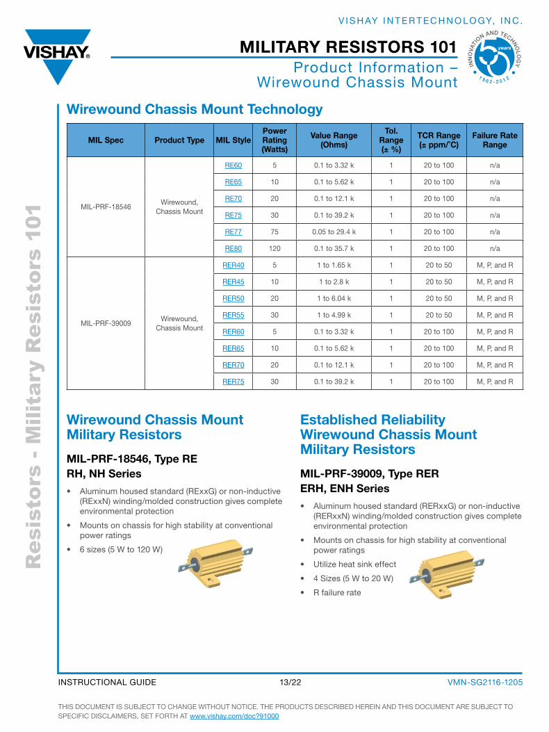
Wirewound chassis mount technology
mil spec Product type mil stylePower rating (Watts)
Value range (ohms)
tol. range (± %)
tcr range (± ppm/˚c)
failure rate range
MIL-PRF-18546 Wirewound,
Chassis Mount
RE60 5 0.1 to 3.32 k 1 20 to 100 n/a
RE65 10 0.1 to 5.62 k 1 20 to 100 n/a
RE70 20 0.1 to 12.1 k 1 20 to 100 n/a
RE75 30 0.1 to 39.2 k 1 20 to 100 n/a
RE77 75 0.05 to 29.4 k 1 20 to 100 n/a
RE80 120 0.1 to 35.7 k 1 20 to 100 n/a
MIL-PRF-39009 Wirewound,
Chassis Mount
RER40 5 1 to 1.65 k 1 20 to 50 M, P, and R
RER45 10 1 to 2.8 k 1 20 to 50 M, P, and R
RER50 20 1 to 6.04 k 1 20 to 50 M, P, and R
RER55 30 1 to 4.99 k 1 20 to 50 M, P, and R
RER60 5 0.1 to 3.32 k 1 20 to 100 M, P, and R
RER65 10 0.1 to 5.62 k 1 20 to 100 M, P, and R
RER70 20 0.1 to 12.1 k 1 20 to 100 M, P, and R
RER75 30 0.1 to 39.2 k 1 20 to 100 M, P, and R
Wirewound chassis mount military resistors
mil-Prf-18546, type re rH, nH series
• aluminum housed standard (RExxg) or non-inductive (RExxN) winding/molded construction gives complete environmental protection
• Mounts on chassis for high stability at conventional power ratings
• 6 sizes (5 W to 120 W)
established reliability Wirewound chassis mount military resistors
mil-Prf-39009, type rer erH, enH series
• aluminum housed standard (RERxxg) or non-inductive (RERxxN) winding/molded construction gives complete environmental protection
• Mounts on chassis for high stability at conventional power ratings
• utilize heat sink effect
• 4 sizes (5 W to 20 W)
• R failure rate
THIs doCuMENT Is subJECT To CHaNgE WITHouT NoTICE. THE PRoduCTs dEsCRIbEd HEREIN aNd THIs doCuMENT aRE subJECT To sPECIFIC dIsCLaIMERs, sET FoRTH aT www.vishay.com/doc?91000
VMN-sg2116-120513/22INsTRuCTIoNaL guIdE
military resistors 101
INN
OVA
TI
ON AND TECHNO
LO
GY
1 9 6 2 - 2 0 1 2
V I s H ay I N T E R T E C H N o Lo gy, I N C .
Res
isto
rs -
Mili
tary
Res
isto
rs 1
01
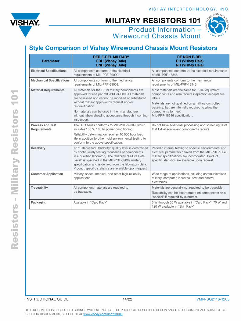
style comparison of Vishay Wirewound chassis mount resistors
Parameterrer e-rel military
erH (Vishay Dale) enH (Vishay Dale)
re non e-rel rH (Vishay Dale) nH (Vishay Dale)
electrical specifications all components conform to the electrical requirements of MIL-PRF-39009.
all components conform to the electrical requirements of MIL-PRF-18546.
mechanical specifications all components conform to the mechanical requirements of MIL-PRF-39009.
all components conform to the mechanical requirements of MIL-PRF-18546.
material requirements all materials for the E-Rel military components are approved for use per MIL-PRF-39009. all materials are baselined and cannot be modified or substituted without military approval by request and/or re-qualification.
No materials can be used in their manufacture without labels showing acceptance through incoming inspection.
Most materials are the same for E-Rel equivalent components and also require inspection acceptance labels.
Materials are not qualified on a military controlled baseline, but are internally required to allow the components to meet MIL-PRF-18546 specification.
Process and test requirements
The RER series conforms to MIL-PRF-39009, which includes 100 % 100 hr power conditioning.
Reliability determination requires 10 000 hour load life in addition to other rigid environmental testing to conform to the above specification.
do not have additional processing and screening tests that E-Rel equivalent components require.
reliability an “Established Reliability” quality level is determined by continuously testing thousands of components in a qualified laboratory. The reliability “Failure Rate Level” is specified in the MIL-PRF-39009 military specification and is derived from the laboratory data. Product specific statistics are available upon request.
Periodic internal testing to specific environmental and electrical parameters derived from the MIL-PRF-18546 military specifications are incorporated. Product specific statistics are available upon request.
customer application Military, space, medical, and other high-reliability applications.
Wide range of applications including communications, military, computer, industrial, test and control electronics.
traceability all component materials are required to be traceable.
Materials are generally not required to be traceable.
Traceability can be incorporated on components as a “special” if required by customer.
Packaging available in “Card Pack” 5 W through 30 W available in “Card Pack”, 70 W and 120 W available in “skin Pack”
Product Information – Wirewound Chassis Mount
THIs doCuMENT Is subJECT To CHaNgE WITHouT NoTICE. THE PRoduCTs dEsCRIbEd HEREIN aNd THIs doCuMENT aRE subJECT To sPECIFIC dIsCLaIMERs, sET FoRTH aT www.vishay.com/doc?91000
VMN-sg2116-120514/22INsTRuCTIoNaL guIdE
military resistors 101
INN
OVA
TI
ON AND TECHNO
LO
GY
1 9 6 2 - 2 0 1 2
V I s H ay I N T E R T E C H N o Lo gy, I N C .
Res
isto
rs -
Mili
tary
Res
isto
rs 1
01Product Information –
dLa L&M / dsCC drawings
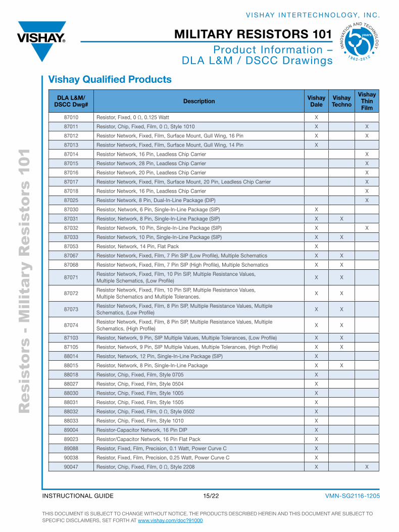
Vishay qualified Products
Dla l&m/Dscc Dwg# Description Vishay
DaleVishay techno
Vishay thin film
87010 Resistor, Fixed, 0 Ω, 0.125 Watt X
87011 Resistor, Chip, Fixed, Film, 0 Ω, style 1010 X X
87012 Resistor Network, Fixed, Film, surface Mount, gull Wing, 16 Pin X X
87013 Resistor Network, Fixed, Film, surface Mount, gull Wing, 14 Pin X
87014 Resistor Network, 16 Pin, Leadless Chip Carrier X
87015 Resistor Network, 28 Pin, Leadless Chip Carrier X
87016 Resistor Network, 20 Pin, Leadless Chip Carrier X
87017 Resistor Network, Fixed, Film, surface Mount, 20 Pin, Leadless Chip Carrier X
87018 Resistor Network, 16 Pin, Leadless Chip Carrier X
87025 Resistor Network, 8 Pin, dual-In-Line Package (dIP) X
87030 Resistor, Network, 6 Pin, single-In-Line Package (sIP) X
87031 Resistor, Network, 8 Pin, single-In-Line Package (sIP) X X
87032 Resistor Network, 10 Pin, single-In-Line Package (sIP) X X
87033 Resistor Network, 10 Pin, single-In-Line Package (sIP) X X
87053 Resistor, Network, 14 Pin, Flat Pack X
87067 Resistor Network, Fixed, Film, 7 Pin sIP (Low Profile), Multiple schematics X X
87068 Resistor Network, Fixed, Film, 7 Pin sIP (High Profile), Multiple schematics X X
87071Resistor Network, Fixed, Film, 10 Pin sIP, Multiple Resistance Values, Multiple schematics, (Low Profile)
X X
87072Resistor Network, Fixed, Film, 10 Pin sIP, Multiple Resistance Values, Multiple schematics and Multiple Tolerances.
X X
87073Resistor Network, Fixed, Film, 8 Pin sIP, Multiple Resistance Values, Multiple schematics, (Low Profile)
X X
87074Resistor Network, Fixed, Film, 8 Pin sIP, Multiple Resistance Values, Multiple schematics, (High Profile)
X X
87103 Resistor, Network, 9 Pin, sIP Multiple Values, Multiple Tolerances, (Low Profile) X X
87105 Resistor, Network, 9 Pin, sIP Multiple Values, Multiple Tolerances, (High Profile) X X
88014 Resistor, Network, 12 Pin, single-In-Line Package (sIP) X
88015 Resistor, Network, 8 Pin, single-In-Line Package X X
88018 Resistor, Chip, Fixed, Film, style 0705 X
88027 Resistor, Chip, Fixed, Film, style 0504 X
88030 Resistor, Chip, Fixed, Film, style 1005 X
88031 Resistor, Chip, Fixed, Film, style 1505 X
88032 Resistor, Chip, Fixed, Film, 0 Ω, style 0502 X
88033 Resistor, Chip, Fixed, Film, style 1010 X
89004 Resistor-Capacitor Network, 16 Pin dIP X
89023 Resistor/Capacitor Network, 16 Pin Flat Pack X
89088 Resistor, Fixed, Film, Precision, 0.1 Watt, Power Curve C X
90038 Resistor, Fixed, Film, Precision, 0.25 Watt, Power Curve C X
90047 Resistor, Chip, Fixed, Film, 0 Ω, style 2208 X X
THIs doCuMENT Is subJECT To CHaNgE WITHouT NoTICE. THE PRoduCTs dEsCRIbEd HEREIN aNd THIs doCuMENT aRE subJECT To sPECIFIC dIsCLaIMERs, sET FoRTH aT www.vishay.com/doc?91000
VMN-sg2116-120515/22INsTRuCTIoNaL guIdE
military resistors 101
INN
OVA
TI
ON AND TECHNO
LO
GY
1 9 6 2 - 2 0 1 2
V I s H ay I N T E R T E C H N o Lo gy, I N C .
Res
isto
rs -
Mili
tary
Res
isto
rs 1
01
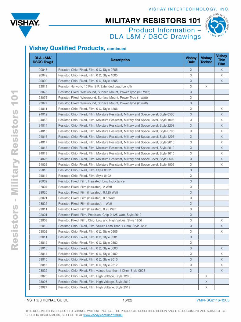
Dla l&m/Dscc Dwg# Description Vishay
DaleVishay techno
Vishay thin film
90048 Resistor, Chip, Fixed, Film, 0 Ω, style 0705 X X
90049 Resistor, Chip, Fixed, Film, 0 Ω, style 1005 X X
90092 Resistor, Chip, Fixed, Film, 0 Ω, style 1505 X X
92013 Resistor Network, 10 Pin, sIP, Extended Lead Length X X
93075 Resistor, Fixed, Wirewound, surface Mount, Power Type (0.5 Watt) X
93076 Resistor, Fixed, Wirewound, surface Mount, Power Type (1 Watt) X
93077 Resistor, Fixed, Wirewound, surface Mount, Power Type (2 Watt) X
94011 Resistor, Chip, Fixed, Film, 0 Ω, style 1206 X X
94012 Resistor, Chip, Fixed, Film, Moisture Resistant, Military and space Level, style 0505 X X
94013 Resistor, Chip, Fixed, Film, Moisture Resistant, Military and space Level, style 1005 X X
94014 Resistor, Chip, Fixed, Film, Moisture Resistant, Military and space Level, style 2208 X X
94015 Resistor, Chip, Fixed, Film, Moisture Resistant, Military and space Level, style 0705 X X
94016 Resistor, Chip, Fixed, Film, Moisture Resistant, Military and space Level, style 1206 X X
94017 Resistor, Chip, Fixed, Film, Moisture Resistant, Military and space Level, style 2010 X X
94018 Resistor, Chip, Fixed, Film, Moisture Resistant, Military and space Level, style 2512 X X
94019 Resistor, Chip, Fixed, Film, Moisture Resistant, Military and space Level, style 1010 X X
94025 Resistor, Chip, Fixed, Film, Moisture Resistant, Military and space Level, style 0502 X X
94026 Resistor, Chip, Fixed, Film, Moisture Resistant, Military and space Level, style 1505 X X
95013 Resistor, Chip, Fixed, Film, style 0302 X
95014 Resistor, Chip, Fixed, Film, style 0402 X
96002 Resistor, Fixed, Film, Insulated, Low Inductance X
97004 Resistor, Fixed, Film (Insulated), 2 Watt X
98020 Resistor, Fixed, Film (Insulated), 0.125 Watt X
98021 Resistor, Fixed, Film (Insulated), 0.5 Watt X
98022 Resistor, Fixed, Film (Insulated), 1 Watt X
99011 Resistor, Fixed, Film (Insulated), 0.25 Watt X
02001 Resistor, Fixed, Film, Precision, Chip 0.125 Watt, style 2012 X
02008 Resistor, Fixed, Film, Chip, Low and High Values, style 1206 X X
02010 Resistor, Chip, Fixed, Film, Values Less Than 1 ohm, style 1206 X X
03002 Resistor, Chip, Fixed, Film, 0 Ω, style 0505 X X
03011 Resistor, Chip, Fixed, Film, 0 Ω, style 0201 X
03012 Resistor, Chip, Fixed, Film, 0 Ω, style 0302 X
03013 Resistor, Chip, Fixed, Film, 0 Ω, style 0603 X X
03014 Resistor, Chip, Fixed, Film, 0 Ω, style 0402 X X
03015 Resistor, Chip, Fixed, Film, 0 Ω, style 2010 X X
03016 Resistor, Chip, Fixed, Film, 0 Ω, style 2512 X X
03022 Resistor, Chip, Fixed, Film, values less than 1 ohm, style 0603 X X
03025 Resistor, Chip, Fixed, Film, High Voltage, style 1206 X
03026 Resistor, Chip, Fixed, Film, High Voltage, style 2010 X
03027 Resistor, Chip, Fixed, Film, High Voltage, style 2512 X
Vishay qualified Products, continued
Product Information – dLa L&M / dsCC drawings
THIs doCuMENT Is subJECT To CHaNgE WITHouT NoTICE. THE PRoduCTs dEsCRIbEd HEREIN aNd THIs doCuMENT aRE subJECT To sPECIFIC dIsCLaIMERs, sET FoRTH aT www.vishay.com/doc?91000
VMN-sg2116-120516/22INsTRuCTIoNaL guIdE
military resistors 101
INN
OVA
TI
ON AND TECHNO
LO
GY
1 9 6 2 - 2 0 1 2
V I s H ay I N T E R T E C H N o Lo gy, I N C .
Res
isto
rs -
Mili
tary
Res
isto
rs 1
01
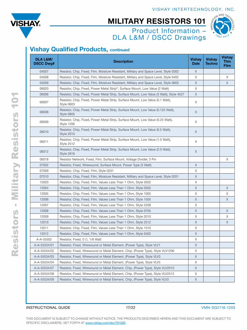
Vishay qualified Products, continued
Product Information – dLa L&M / dsCC drawings
Dla l&m/Dscc Dwg# Description Vishay
DaleVishay techno
Vishay thin film
04007 Resistor, Chip, Fixed, Film, Moisture Resistant, Military and space Level, style 0302 X
04008 Resistor, Chip, Fixed, Film, Moisture Resistant, Military and space Level, style 0402 X X
04009 Resistor, Chip, Fixed, Film, Moisture Resistant, Military and space Level, style 0603 X X
06003 Resistor, Chip, Fixed, Power Metal strip®, surface Mount, Low Value (2 Watt) X
06006 Resistor, Chip, Fixed, Power Metal strip, surface Mount, Low Value (3 Watt), style 4527 X
06007Resistor, Chip, Fixed, Power Metal strip, surface Mount, Low Value (0.1 Watt), style 0603
X
06008Resistor, Chip, Fixed, Power Metal strip, surface Mount, Low Value (0.125 Watt), style 0805
X
06009Resistor, Chip, Fixed, Power Metal strip, surface Mount, Low Value (0.25 Watt), style 1206
X
06010Resistor, Chip, Fixed, Power Metal strip, surface Mount, Low Value (0.5 Watt), style 2010
X
06011Resistor, Chip, Fixed, Power Metal strip, surface Mount, Low Value (1.0 Watt), style 2512
X
06012Resistor, Chip, Fixed, Power Metal strip, surface Mount, Low Value (2.0 Watt), style 2816
X
06018 Resistor Network, Fixed, Film, surface Mount, Voltage divider, 3 Pin X
07002 Resistor, Fixed, Wirewound, surface Mount, Power Type (3 Watt) X
07009 Resistor, Chip, Fixed, Film, style 0201 X
07010 Resistor, Chip, Fixed, Film, Moisture Resistant, Military and space Level, style 0201 X
12003 Resistor, Chip, Fixed, Film, Values Less Than 1 ohm, style 0502 X
12004 Resistor, Chip, Fixed, Film, Values Less Than 1 ohm, style 0505 X X
12005 Resistor, Chip, Fixed, Film, Values Less Than 1 ohm, style 1005 X X
12006 Resistor, Chip, Fixed, Film, Values Less Than 1 ohm, style 1505 X X
12007 Resistor, Chip, Fixed, Film, Values Less Than 1 ohm, style 2208 X
12008 Resistor, Chip, Fixed, Film, Values Less Than 1 ohm, style 0705 X X
12009 Resistor, Chip, Fixed, Film, Values Less Than 1 ohm, style 2010 X X
12010 Resistor, Chip, Fixed, Film, Values Less Than 1 ohm, style 2512 X X
12011 Resistor, Chip, Fixed, Film, Values Less Than 1 ohm, style 1010 X
12012 Resistor, Chip, Fixed, Film, Values Less Than 1 ohm, style 0402 X
a-a-55502 Resistor, Fixed, 0 Ω, 1/8 Watt X
a-a-55534/01 Resistor, Fixed, Wirewound or Metal Element, (Power Type), style VLV1 X
a-a-55534/02 Resistor, Fixed, Wirewound or Metal Element, Chip, (Power Type), style VLV1206 X
a-a-55534/03 Resistor, Fixed, Wirewound or Metal Element, (Power Type), style VLV3 X
a-a-55534/04 Resistor, Fixed, Wirewound or Metal Element, (Power Type), style VLV5 X
a-a-55534/07 Resistor, Fixed, Wirewound or Metal Element, Chip, (Power Type), style VLV2010 X
a-a-55534/08 Resistor, Fixed, Wirewound or Metal Element, Chip, (Power Type), style VLV2512 X
a-a-55534/09 Resistor, Fixed, Wirewound or Metal Element, Chip, (Power Type), style VLV2 X
THIs doCuMENT Is subJECT To CHaNgE WITHouT NoTICE. THE PRoduCTs dEsCRIbEd HEREIN aNd THIs doCuMENT aRE subJECT To sPECIFIC dIsCLaIMERs, sET FoRTH aT www.vishay.com/doc?91000
VMN-sg2116-120517/22INsTRuCTIoNaL guIdE
military resistors 101
INN
OVA
TI
ON AND TECHNO
LO
GY
1 9 6 2 - 2 0 1 2
V I s H ay I N T E R T E C H N o Lo gy, I N C .
Res
isto
rs -
Mili
tary
Res
isto
rs 1
01Terminology
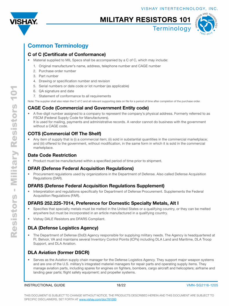
common terminologyc of c (certificate of conformance)• Material supplied to MIL specs shall be accompanied by a C of C, which may include:
1. original manufacturer’s name, address, telephone number and CagE number2. Purchase order number3. Part number4. drawing or specification number and revision5. serial numbers or date code or lot number (as applicable)6. Qa signature and date7. statement of conformance to all requirements
Note: The supplier shall also retain the C of C and all relevant supporting data on file for a period of time after completion of the purchase order.
caGe code (commercial and Government entity code)• a five-digit number assigned to a company to represent the company’s physical address. Formerly referred to as
FsCM (Federal supply Code for Manufacturers). It is used for mailing, payments and administrative records. a vendor cannot do business with the government without a CagE code.
cots (commercial off the shelf)• any item of supply that is (i) a commercial item; (ii) sold in substantial quantities in the commercial marketplace;
and (iii) offered to the government, without modification, in the same form in which it is sold in the commercial marketplace.
Date code restriction• Product must be manufactured within a specified period of time prior to shipment.
Dfar (Defense federal acquisition regulations)• Procurement regulations used by organizations in the department of defense. also called defense acquisition
Regulations (daR).
Dfars (Defense federal acquisition regulations supplement)• Interpretation and regulations specifically for department of defense Procurement. supplements the Federal
acquisition Regulations (FaR).
Dfars 252.225-7014, Preference for Domestic specialty metals, alt i• specifies that specialty metals must be melted in the united states or a qualifying country, or they can be melted
anywhere but must be incorporated in an article manufactured in a qualifying country.
• Vishay daLE Resistors are dFaRs Compliant.
Dla (Defense logistics agency)
• The department of defense (dod) agency responsible for supplying military needs. The agency is headquartered at Ft. belvoir, Va and maintains several Inventory Control Points (ICPs) including dLa Land and Maritime, dLa Troop support, and dLa aviation.
Dla aviation (former Dscr)
• serves as the aviation supply chain manager for the defense Logistics agency. They support major weapon systems and are one of the u.s. military’s integrated materiel managers for repair parts and operating supply items. They manage aviation parts, including spares for engines on fighters, bombers, cargo aircraft and helicopters; airframe and landing gear parts; flight safety equipment; and propeller systems.
THIs doCuMENT Is subJECT To CHaNgE WITHouT NoTICE. THE PRoduCTs dEsCRIbEd HEREIN aNd THIs doCuMENT aRE subJECT To sPECIFIC dIsCLaIMERs, sET FoRTH aT www.vishay.com/doc?91000
VMN-sg2116-120518/22INsTRuCTIoNaL guIdE
military resistors 101
INN
OVA
TI
ON AND TECHNO
LO
GY
1 9 6 2 - 2 0 1 2
V I s H ay I N T E R T E C H N o Lo gy, I N C .

Res
isto
rs -
Mili
tary
Res
isto
rs 1
01Terminology
Dla land and maritime (former Dscc)• serves as the Maritime and Land weapons systems supply chain manager for the defense Logistics agency. dLa
L&M is one of the u.s. Military’s largest suppliers of weapon systems spare parts, and they also manage the MIL specs and drawings for the dLa.
Dla troop support (former DscP)• Provides united states armed services members with food, clothing, textiles, medicines, medical equipment, and
construction supplies and equipment. They also support united states humanitarian and disaster relief efforts.
DPa (Defense Production act)• under authority of the defense Production act of 1950 and related executive order 12656, the Commerce
department is charged with identifying critical defense-related industries, assessing their capability to meet peacetime and national security needs, identifying current and potential production constraints, and proposing remedial actions as appropriate. Title I of the dPa requires that: (i) contracts or orders relating to certain approved defense and energy programs be accepted and performed on a preferential basis over all other contracts and orders and (ii) materials, facilities, and services be allocated in such a manner as to promote approved programs, facilities, and services be allocated in such a manner as to promote approved programs.
DPas (Defense Priorities and allocation system)• The goals of the dPas are to (i) assure the timely availability of industrial resources to meet current national defense
requirements and (ii) provide a framework for rapid industrial expansion in case of a national emergency.
– There are two levels of priority established by this regulation, identified by the rating symbols “do ” and “dX”. all do rated orders have equal priority with each other and take preference over unrated orders. all dX orders have equal priority with each other and take preference over do rated orders and unrated orders.
Dsc, Dscc, DscP, Dscr• Former abbreviations for the supply Centers, which procure supplies for the Military. Each supply Center manages
different types of items.
• dsC = defense supply Center
– dsCC = defense supply Center Columbus (Columbus, oH) – now dLa Land and Maritime
– Maritime and land weapon systems support
– dsCP = defense supply Center Philadelphia (Philadelphia, Pa) – now dLa Troop support
– Food, clothing, medical, construction, and equipment support
– dsCR = defense supply Center Richmond (Richmond, Va) – now dLa aviation
– aviation weapon systems and environmental logistics support
eDi (electronic Data interchange)• The electronic communications of business transactions; specifically the exchange of trade-related documents such
as purchase orders, invoices, and corporate Electronic Funds Transfer (EFTs) in a standard format.
esD (electrostatic sensitive Devices)• The devices supplied under contract shall be packaged in accordance with the latest revision of the MIL-sTd- 1686
(Electrostatic discharge Control Program for Protection of Electronic devices) and MIL-HdbK-263 (Esd Handbook for Protection Parts, assemblies and Equipments). Packaging shall be marked with an Esd cautionary note or symbol.
e-rel (established reliability)• a quantitative maximum failure rate demonstrated under controlled conditions specified in a department of defense
specification and usually expressed as percent failures per thousand hours of test.
THIs doCuMENT Is subJECT To CHaNgE WITHouT NoTICE. THE PRoduCTs dEsCRIbEd HEREIN aNd THIs doCuMENT aRE subJECT To sPECIFIC dIsCLaIMERs, sET FoRTH aT www.vishay.com/doc?91000
VMN-sg2116-120519/22INsTRuCTIoNaL guIdE
military resistors 101
INN
OVA
TI
ON AND TECHNO
LO
GY
1 9 6 2 - 2 0 1 2
V I s H ay I N T E R T E C H N o Lo gy, I N C .
Res
isto
rs -
Mili
tary
Res
isto
rs 1
01Terminology
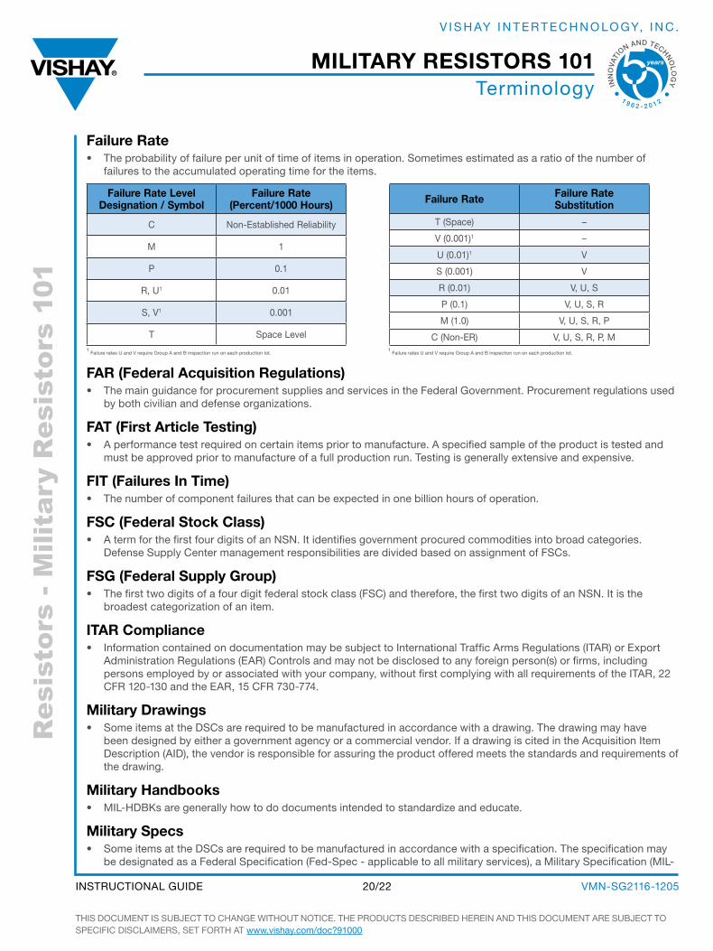
failure rate• The probability of failure per unit of time of items in operation. sometimes estimated as a ratio of the number of
failures to the accumulated operating time for the items.
far (federal acquisition regulations)• The main guidance for procurement supplies and services in the Federal government. Procurement regulations used
by both civilian and defense organizations.
fat (first article testing)• a performance test required on certain items prior to manufacture. a specified sample of the product is tested and
must be approved prior to manufacture of a full production run. Testing is generally extensive and expensive.
fit (failures in time)• The number of component failures that can be expected in one billion hours of operation.
fsc (federal stock class)• a term for the first four digits of an NsN. It identifies government procured commodities into broad categories.
defense supply Center management responsibilities are divided based on assignment of FsCs.
fsG (federal supply Group)• The first two digits of a four digit federal stock class (FsC) and therefore, the first two digits of an NsN. It is the
broadest categorization of an item.
itar compliance• Information contained on documentation may be subject to International Traffic arms Regulations (ITaR) or Export
administration Regulations (EaR) Controls and may not be disclosed to any foreign person(s) or firms, including persons employed by or associated with your company, without first complying with all requirements of the ITaR, 22 CFR 120-130 and the EaR, 15 CFR 730-774.
military Drawings• some items at the dsCs are required to be manufactured in accordance with a drawing. The drawing may have
been designed by either a government agency or a commercial vendor. If a drawing is cited in the acquisition Item description (aId), the vendor is responsible for assuring the product offered meets the standards and requirements of the drawing.
military Handbooks• MIL-HdbKs are generally how to do documents intended to standardize and educate.
military specs• some items at the dsCs are required to be manufactured in accordance with a specification. The specification may
be designated as a Federal specification (Fed-spec - applicable to all military services), a Military specification (MIL-
1 Failure rates u and V require group a and b inspection run on each production lot.
1 Failure rates u and V require group a and b inspection run on each production lot.
failure rate failure rate substitution
T (space) –
V (0.001)1 –
u (0.01)1 V
s (0.001) V
R (0.01) V, u, s
P (0.1) V, u, s, R
M (1.0) V, u, s, R, P
C (Non-ER) V, u, s, R, P, M
failure rate level Designation / symbol
failure rate (Percent/1000 Hours)
C Non-Established Reliability
M 1
P 0.1
R, u1 0.01
s, V1 0.001
T space Level
THIs doCuMENT Is subJECT To CHaNgE WITHouT NoTICE. THE PRoduCTs dEsCRIbEd HEREIN aNd THIs doCuMENT aRE subJECT To sPECIFIC dIsCLaIMERs, sET FoRTH aT www.vishay.com/doc?91000
VMN-sg2116-120520/22INsTRuCTIoNaL guIdE
military resistors 101
INN
OVA
TI
ON AND TECHNO
LO
GY
1 9 6 2 - 2 0 1 2
V I s H ay I N T E R T E C H N o Lo gy, I N C .
Res
isto
rs -
Mili
tary
Res
isto
rs 1
01Terminology
spec - used by a specific service) or a commercial specification such as North american specification (Nas) or american National standards Institute (aNsI). If a specification is cited in the acquisition Item description (aId), the vendor is responsible for assuring the product offered meets the requirements of the specification.
military standards• MIL-sTds are generally documents that imposed requirements and give details on what to do.
mil-stD-202G test methods standard electronic and electrical component Parts• This military standard establishes uniform methods for testing electronic and electrical component parts,
including basic environmental tests to determine resistance to deleterious effects of natural elements and conditions surrounding military operations, and physical and electrical tests.
mil-stD-883f test method standard microcircuits• This military standard establishes uniform methods, controls, and procedures for testing microelectronic
devices suitable for use within Military and aerospace electronic systems including basic environmental tests and other controls and constraints as have been deemed necessary to ensure a uniform level of quality and reliability suitable to the intended applications of those devices.
mtBf (mean time Between failures)• The average time a component works without failure. It is the number of failures divided by the hours under
observation.
niin (national item identification number)• The second of two main parts of the National stock Number. The NIIN is a unique number with no two items
having the same NIIN. an item can be tracked in technical files using just the NIIN. Contract files require the full NsN to track information.
nsn (national stock number)• a unique government tracking number assigned by the general services administration consisting of a Federal
stock Class (FsC) and a National Item Identification Number (NIIN). The number is used by requisitioners to identify the item needed and is associated with all buys related to that item. More than one part number may be associated with an NsN; however, all parts associated will have to be the same in form, fit and function.
Prohibited materials (tin Whiskers)• unless otherwise specified in the product specification, material supplied meet the requirements of aNsI/
J-sTd-002, Category 3 Test Method a, b, or C as applicable. In addition, constructions and finishes containing pure tin are prohibited unless they contain a minimum of 3 percent by weight alloying element(s) (i.e. lead, silver, etc.).
qPl (qualified Products list)• a list of pre-tested qualified manufacturers and products as they related to a specific military specification.
a solicitation specifying a QPL restriction requires contractors to supply only the source and part number specified on the QPL list.
• Failure Rated QPL
– Established Reliability product with a verified Failure Rate that has been qualified to a military specification.
• Non-Failure Rated QPL
– Product without a verified Failure Rate that has been qualified to a military specification or drawing.
single lot traceability• Items provided in accordance with this purchase order clause requires each shipment (i) be from only one
oEM; (ii) be from one Manufacturing Lot; (iii) components that are too small to have the Lot Code marked on them are to have their packaging identified with the appropriate Lot Code marking / serial number. also known as single Lot date Code (sLdC) and date Code (dC).
THIs doCuMENT Is subJECT To CHaNgE WITHouT NoTICE. THE PRoduCTs dEsCRIbEd HEREIN aNd THIs doCuMENT aRE subJECT To sPECIFIC dIsCLaIMERs, sET FoRTH aT www.vishay.com/doc?91000
VMN-sg2116-120521/22INsTRuCTIoNaL guIdE
military resistors 101
INN
OVA
TI
ON AND TECHNO
LO
GY
1 9 6 2 - 2 0 1 2
V I s H ay I N T E R T E C H N o Lo gy, I N C .
Res
isto
rs -
Mili
tary
Res
isto
rs 1
01Resistive Products
THIs doCuMENT Is subJECT To CHaNgE WITHouT NoTICE. THE PRoduCTs dEsCRIbEd HEREIN aNd THIs doCuMENT aRE subJECT To sPECIFIC dIsCLaIMERs, sET FoRTH aT www.vishay.com/doc?91000
VMN-sg2116-120522/22INsTRuCTIoNaL guIdE
military resistors 101
INN
OVA
TI
ON AND TECHNO
LO
GY
1 9 6 2 - 2 0 1 2
V I s H ay I N T E R T E C H N o Lo gy, I N C .
tHe americas
uniteD statesVIsHay aMERICas oNE gREENWICH PLaCE sHELToN, CT 06484 uNITEd sTaTEs PH: +1-402-563-6866 FaX: +1-402-563-6296
asia
sinGaPoreVIsHay INTERTECHNoLogy asIa PTE LTd.37a TaMPINEs sTREET 92 #07-00sINgaPoRE 528886 PH: +65-6788-6668 FaX: +65-6788-0988
P.r. cHinaVIsHay CHINa Co., LTd.15d, suN ToNg INFoPoRT PLaZa55 HuaI HaI WEsT RoadsHaNgHaI 200030 P.R. CHINaPH: +86-21-5258 5000FaX: +86-21-5258 7979
JaPanVIsHay JaPaN Co., LTd.sHIbuya PREsTIgE bLdg. 4F 3-12-22, sHIbuya sHIbuya-Ku ToKyo 150-0002 JaPaN PH: +81-3-5466-7150 FaX: +81-3-5466-7160
euroPe
GermanyVIsHay ELECTRoNIC gMbHdR.-FELIX-ZaNdMaN-PLaTZ 1 95100 sELb gERMaNy PH: +49-9287-71-0 FaX: +49-9287-70435 franceVIsHay s.a.199, bd dE La MadELEINE 06003 NICE, CEdEX 1 FRaNCE PH: +33-4-9337-2727 FaX: +33-4-9337-2726 uniteD kinGDomVIsHay LTd.suITE 6C, ToWER HousEsT. CaTHERINE’s CouRTsuNdERLaNd ENTERPRIsE PaRKsuNdERLaNd sR5 3XJ uNITEd KINgdoMPH: +44-191-516-8584FaX: +44-191-549-9556
WoRLdWIdE saLEs CoNTaCTs
Legal Disclaimer Noticewww.vishay.com Vishay
Revision: 02-Oct-12 1 Document Number: 91000
DisclaimerALL PRODUCT, PRODUCT SPECIFICATIONS AND DATA ARE SUBJECT TO CHANGE WITHOUT NOTICE TO IMPROVERELIABILITY, FUNCTION OR DESIGN OR OTHERWISE.
Vishay Intertechnology, Inc., its affiliates, agents, and employees, and all persons acting on its or their behalf (collectively,“Vishay”), disclaim any and all liability for any errors, inaccuracies or incompleteness contained in any datasheet or in any otherdisclosure relating to any product.
Vishay makes no warranty, representation or guarantee regarding the suitability of the products for any particular purpose orthe continuing production of any product. To the maximum extent permitted by applicable law, Vishay disclaims (i) any and allliability arising out of the application or use of any product, (ii) any and all liability, including without limitation special,consequential or incidental damages, and (iii) any and all implied warranties, including warranties of fitness for particularpurpose, non-infringement and merchantability.
Statements regarding the suitability of products for certain types of applications are based on Vishay’s knowledge of typicalrequirements that are often placed on Vishay products in generic applications. Such statements are not binding statementsabout the suitability of products for a particular application. It is the customer’s responsibility to validate that a particularproduct with the properties described in the product specification is suitable for use in a particular application. Parametersprovided in datasheets and/or specifications may vary in different applications and performance may vary over time. Alloperating parameters, including typical parameters, must be validated for each customer application by the customer’stechnical experts. Product specifications do not expand or otherwise modify Vishay’s terms and conditions of purchase,including but not limited to the warranty expressed therein.
Except as expressly indicated in writing, Vishay products are not designed for use in medical, life-saving, or life-sustainingapplications or for any other application in which the failure of the Vishay product could result in personal injury or death.Customers using or selling Vishay products not expressly indicated for use in such applications do so at their own risk. Pleasecontact authorized Vishay personnel to obtain written terms and conditions regarding products designed for such applications.
No license, express or implied, by estoppel or otherwise, to any intellectual property rights is granted by this document or byany conduct of Vishay. Product names and markings noted herein may be trademarks of their respective owners.
Material Category PolicyVishay Intertechnology, Inc. hereby certifies that all its products that are identified as RoHS-Compliant fulfill thedefinitions and restrictions defined under Directive 2011/65/EU of The European Parliament and of the Councilof June 8, 2011 on the restriction of the use of certain hazardous substances in electrical and electronic equipment(EEE) - recast, unless otherwise specified as non-compliant.
Please note that some Vishay documentation may still make reference to RoHS Directive 2002/95/EC. We confirm thatall the products identified as being compliant to Directive 2002/95/EC conform to Directive 2011/65/EU.
Vishay Intertechnology, Inc. hereby certifies that all its products that are identified as Halogen-Free follow Halogen-Freerequirements as per JEDEC JS709A standards. Please note that some Vishay documentation may still make referenceto the IEC 61249-2-21 definition. We confirm that all the products identified as being compliant to IEC 61249-2-21conform to JEDEC JS709A standards.