Embed Size (px)
Citation preview

Metal Roof Installation Manual

ACKNOWLEDGEMENTS The Metal Construction Association (MCA) would like to gratefully acknowledge Ken Buchinger, Jim Bush, Bill Croucher, Rob Haddock and MCA technical director Scott Kriner who have given generously of their time and talent in the production of this Training Manual. Additionally, we would also like to thank the Metal Building Manufacturers Association (MBMA) for granting permission to utilize their 2012 Metal Roofing Systems Design Manual as a source document for this Training Manual, with information being excerpted from the following chapters: Chapter 1-Systems Components; Chapter 2-Substrates; Chapter 4-Retrofits; Chapter 7-Installation and Maintenance; and Chapter 12-Metal Roof Details. That material is reprinted with permission and as noted in Training Manual Chapters 10, 11, 12, 13 and 16. The complete MBMA reference is available at www.mbmamanual.com. We would like to further acknowledge the following individuals and organizations that contributed images to this manual. All images were reprinted with permission. Ken Buchinger, MBCI Figures 2-3b Figures 3-5, 3-11, 3-12, 3-13, 3-14, 3-15, 3-16 Figures 4-17 Figures 7-4, 7-8, 7-9, 7-12, 7-13 Figures 8-8, 8-9, 8-12, 8-15, 8-17, 8-25, 8-28, 8-29, 8-30 Figures 10-22, 10-40, 10-41 (partial), 10-42, 10-44, 10-45, 10-46, 10-48, 10-49, 10-59, 10-67 Figures 12-3a, 12-3b, 12-10 Figure 13-1 Figures 14-6, 14-26, 14-27, 14-28, 14-29 Figures 16-2, 16-21, 16-22, 16-23, 16-24, 16-31 (partial), 16-32 Figures 17-3, 17-4, 17-9 Figures 19-2, 19-11, 19-12 (partial), 19-13 (partial), 19-14, 19-16 (partial) Jim Bush, ATAS International, Inc. Figure 4-10 Figures 5-11, 5-19, 5-20 Figures 8-34, 8-35 (partial) Table 10-1 Figure 13-7 Bill Croucher, Fabral Figure 8-19 Rob Haddock, Metal Roof Advisory Group, Ltd. Figures 2-5, 2-6, 2-7, 2-8 Figures 3-1, 3-2, 3-4, 3-7, 3-9, 3-10 Figures 4-4, 4-5

ACKNOWLEDGEMENTS Figures 7-14, 7-17 (left), 7-20 Figures 8-13, 8-14, 8-18, 8-19, 8-20, 8-22, 8-23, 8-33 Figures 9-10, 9-17 Figures 10-23, 10-31, 10-32, 10-33, 10-35, 10-37, 10-43, 10-47 Figures 11-5, 11-6, 11-7, 11-8, 11-12, 11-18 Figures 12-11, 12-12 Figures 15-1, 15-2, 15-3, 15-4, 15-6, 15-8, 15-9, 15-15 Figures 16-25, 16-26, 16-29 Metal Building Manufacturers Association Figures 6-2c, 6-9 Figures 8-10 Figure 10-2, 10-4, 10-40,10-71,10-72,10-73,10-74,10-80 Figure 13-13, 13-14,13-15,13-16,13-17,13-18 Figures 14-1, 14-20, 14-22, 14-25 Figures 16-14, 16-17, 16-18, 16-27 Figures 20-2, 20-3, 20-4, 20-5, 20-12 (top), 20-13, 20-14 National Roofing Contractors Association Figures 4-1, 4-13 Figure 5-16 Figures 8-3, 8-4, 8-5, 8-6 Figures 10-3,10-9, 10-10,10-14,10-15,10-24,10-25,10-26,10-27,10-28,10-34,10-36,10-50,10-51,10-52,10-53,10-54,10-55,10-56,10-57,10-58,10-60,10-61,10-62,10-63,10-64,10-65,10-66,10-68,10-69,10-70,10-75,10-76,10-81,10-82 Figures 13-19a, 13-20, 13-21, 13-22, 13-23 Figures 14-21, 14-23, 14-24, 14-32, 14-33, 14-34 Figures 15-10, 15-13

Table of Contents
Chapters:
1. INTRODUCTION 2. METAL ROOFING: A FAMILY OF PRODUCTS / HISTORY OF METAL ROOFING 3. INTRO TO METAL ROOFING MATERIALS 4. PANEL TYPES 5. PANEL ATTRIBUTES / PROFILES 6. ROOF DECK SUBSTRATES 7. PANEL CONNECTIONS 8. COMMON ROOF ACCESSORIES 9. SAFETY ISSUES
10. ROOFING DESIGN 11. DELIVERY, RECEIPT, STORAGE, AND HANDLING OF MATERIALS 12. TOOLS AND FIELD OPERATIONS 13. SEALANTS 14. FASTENERS 15. SEAM JOINING 16. PANEL INSTALLATION 17. MAINTENANCE 18. CODES / STANDARDS AND SPECIFICATIONS 19. INSTALLER CHECKLISTS 20. RE-ROOFING
Appendices: 1. GLOSSARY 2. ABBREVIATIONS AND ACRONYMS 3. RESOURCE MATERIAL 4. DISCLAIMER

Chapter 1: Introduction Chapter Contents 1. Introduction ....................................................................................................... 1-1
1.1 MCA Installer Training Manual .................................................................. 1-1
1.1.1 Purpose of the Manual ....................................................................
1.1.2 Using This Manual ...........................................................................
1.1.3 Skill and Knowledge Requirements of the Installer .....................
1.1.4 Responsibility of the Various Trades ............................................
1.1.5 Timeliness of Information ...............................................................
1.2 Development of the Training Manual .......................................................
1-1
1-1
1-1
1-2
1-2
1-2
1.3 Acknowledgments ..................................................................................... 1-2

INTRODUCTION: CHAPTER 1
1. INTRODUCTION This installation training manual addresses the installation of metal roofing material and related accessories. It includes information pertaining to both new construction reroofing and retrofit projects.
Important Note: Different roof types require specific installation techniques. The information provided in this manual does not supercede installation instructions provided by the manufacturer. Always consult the manufacturer's instructions.
1.1 MCA Installer Training Manual
1.1.1 Purpose of the Manual The MCA installation training manual was developed to improve the installation of metal roofing within the construction industry. The goal is to eliminate avoidable problems and reduce the need for additional work due to callbacks.
This installation training manual is intended for installers of metal roofs, related products and accessories.
Other professionals involved in the construction industry can benefit from this training manual. This includes architects, specification writers, contractors, building owners, manufacturers, and numerous others.
The specific objectives of the MCA installation training manual are to:
• Promote consistent, high quality installations; decreasing installation deficiencies; minimizing product failures and callbacks; while promoting energy efficiency and, thereby, lowering the ultimate cost to the consumer.
• Provide installers with the basic knowledge necessary for proper installation of typical
metal roofing products when following the manufacturer's installation instructions;
• Promote installer safety practices.
1.1.2 Using This Manual This installation training manual was developed to provide information regarding the installation of most metal roofing products, and to serve as a reference for most types of metal roofing products and applications. This manual does not address the unique characteristics of factory assembled insulated metal panel roofs or special environments such as cold storage. The manual provides an overview of information relating to:
• The History of, and Introduction to, Metal Roofing Products and Materials
• Panel Attributes
• Roofing Design
• Sealants and Fasteners
• Installation of Products
• Common Accessories
• Specifications and Codes
• Final Cleaning and Inspection
• Re-roofing
• Installer Checklists
1.1.3 Skill and Knowledge Requirements of the Installer
This installation training manual assumes that the installer possesses the following basic knowledge and skills: 1. Basic measuring skills 2. A basic understanding of construction
methods and techniques 3. An understanding of the proper use of
tools normal to the roofing trade The contributors to this document attempted to include the basic information needed.
1-1

INTRODUCTION: CHAPTER 1 However, it is not practical to include all information related to each product and its design options. In the event that an installer has any questions, or faces a situation not addressed in these materials, it is imperative that such uncertainties be resolved through consultation with the responsible parties before work is begun.
1.1.4 Responsibility of the Various Trades
For the purpose of this training manual, an installer is defined as someone who sets, anchors, seals, and/or applies metal roofing products and necessary flashing and trim. No differentiation is specified between a new construction installer and a replacement (retrofit) installer in this manual. Some of an installer’s tasks may be performed by other individuals. As an example, one party may dry-in the roof by applying the peel and stick underlayment, another install the panels, and a third party install pipe penetrations and pipe boots.
Although the installer is responsible for the quality of the work performed, others (building contractor, developer, architect, etc.) are often the "approving authority" or "responsible parties” that make specific decisions that affect the installation. The approving authority is responsible for coordination and checking the quality of the work done by the various trades associated with the roofing. The construction sequence, proper coordination, and proper integration of all of the various building components are essential to the long-term performance of any completed installation. This is especially true of metal roofing.
It is desirable that the installer be actively involved in any additional roof work-related activities that may take place during a project, including those performed after the installation, if possible.
1.1.5 Timeliness of Information
This manual provides information which is current as of the date of publication. Always check the manufacturer’s instructions and current information provided by the building and roofing industry for updates.
1.2 Development of the Installer Training Manual
The installation training manual is based on industry-accepted practices and principles that have been developed over the years by members of the MCA (Metal Construction Association) This association recognizes the need for consistent installation practices and is dedicated to the development of installation best practices. The best practices developed have allowed for the creation of this training manual offered by the MCA.
Experienced individuals and experts in the field provided input throughout the development of the installation training manual. A team of individuals from MCA was formed to assist in developing the manual based on material submitted or recommended by the MCA.
In addition, this training manual incorporates information offered by MCA members who are manufacturers and/or suppliers. Much of the information provided was incorporated into the language and graphics.
1.3 Acknowledgments
This installation training manual was developed with the support of the MCA and its many members. Through their efforts and dedication, both technical and financial, this program was made possible. Gratitude is extended to each individual and the organizations they represent.
1-2

INTRODUCTION: CHAPTER 1 Notes:
____________________________________________________________________________________________________
1-3

Chapter 2: Metal Roofing: A Family of Products / History of Metal Roofing Chapter Contents
2. Metal Roofing: A Family of Products / History of Metal Products ... 2-1
2.1 Metal Roofing: A Family of Products ........................................................
2.2 History of Metal Roofing .............................................................................
2-1
2-2
2.2.1 Earliest Usages ..................................................................................
2.2.2 European Influences .........................................................................
2.2.3 Modern Production and Growth .......................................................
2.2.4 Fabrication Methods ..........................................................................
2.2.4.1 Hand Tools and Soldering ....................................................
2.2.4.2 Brake Forming .......................................................................
2.2.4.3 Corrugating, Roll Forming, and Press Brakes ....................
2-2
2-3
2-3
2-3
2-3
2-4
2-4

METAL ROOFING: CHAPTER 2 A FAMILY OF PRODUCTS / HISTORY OF METAL ROOFING
2. METAL ROOFING: A FAMILY OF PRODUCTS /
HISTORY OF METAL ROOFING When installing a metal roof, it is important to realize that a system of individual components is being installed that are related to each other, and that depend on the proper installation of each part in order for the system to perform correctly. Understanding this “family of products” and how they are related will make any installation job easier, safer, and less confusing.
Metal roofing has always been considered a premium roofing material. A brief look at how metal roofing developed over the centuries will help the installer understand why and how various roof styles, types of panels, materials, and seam methods were developed. Each was developed to solve a roofing problem. Some were developed to meet unique roofing situations.
2.1 Metal Roofing : A Family of Products
A typical metal roof system is composed of five primary components an installer needs to consider in any application. They are:
• Substructure • Roof panels & trim • Fasteners • Common roof accessories • Support structure
The substructure is the foundation, or base, to which the top roof panel is attached. Think of it as the first thing that is found when the roof’s top layer is pulled back. The two main types of substrates are called solid deck and open framing (Figure 2-1). Decking material may be either wood or metal, and some substrates may have rigid insulation.
Solid Deck Substrate Open framing Substrate
Figure 2-1 Types of Substrates
Roof panels and trim make up the top layer of the roof and are directly exposed to the weather and the environment. These products can be made from:
• Natural metals o Aluminum o Copper o Zinc
• Alloys o Aluminum/Zinc o Stainless Steel
• Metallic coated materials o Galvanized o Galvalume®
They may be in the form of sheets, panels, or smaller individual pieces, much like traditional asphalt shingles, wood, slate, or tile facsimiles. The sizes and shapes of metal panels and trim pieces may vary widely, but are light in weight, and usually easy to install. (Figure 2-2) Most panel styles and varieties are available painted or unpainted.
Figure 2-2
A Standing Seam Roof Panel
2-1

METAL ROOFING: CHAPTER 2 A FAMILY OF PRODUCTS / HISTORY OF METAL ROOFING Installation of a metal roof requires the use of a variety of styles and types of fasteners and or clips. These are the components responsible for keeping the roof on the structure. Examples are shown in Figure 2-3a and Figure 2-3b. The exact style and size of the fastener will depend on the roof panel to be installed, as well as design requirements of the roof. A roof installed in a high wind zone will require a different fastener and spacing than one installed in a milder environment. Other considerations, such as snow and ice loading, and building codes, may also change the type and amount of fasteners and clips required for any installation.
Figure 2-3a
Typical Fasteners
Figure 2-3b
Various Clip Examples Common roof accessories will be a part of every installation. Every installer needs to be familiar with such common accessory installations as vents, curbs, and pipe
penetrations. Depending on the job or location, the installer will also need to be familiar with installation of accessories like skylights, snow guards, and solar panel mounting. Be aware that some of these accessories will require fasteners that may not be a part of a standard roof installation.
The support structure (Figure 2-4) for the roof is responsible for holding the weight of the installed roof, including the substructure and any insulation or accessories. This support system must also take into consideration additional roof loads from wind, snow, ice, roof-installed equipment, and any foot traffic the roof will experience, and transfer those loads to the structure. The support structure usually is a framing system of wood, metal, stone, or concrete.
Figure 2-4
Support Structure Each member of this “family” must be selected and installed properly in order for the roof to provide the protection, performance, and life expectancy for which it was designed.
Each of these components will be addressed and discussed in more detail, and from an installer’s perspective, throughout this manual.
2.2 History of Metal Roofing
2.2.1 Earliest Usages
More than 2,000 years ago, smiths hammered out small roof plates of metal. Throughout its history, into the present day,
2-2

METAL ROOFING: CHAPTER 2 A FAMILY OF PRODUCTS / HISTORY OF METAL ROOFING metal roofing has always been considered a premium roofing system, often reserved for the most important of buildings and centers of worship. In a few extreme cases, metal roofs have even been made out of gold! The long life of metal roofs is well known and documented. There are metal roofs hundreds of years old that are performing well. The earliest metal roofs were built in the Middle East around 675 A.D. or even earlier. They were especially suited to the domed and rounded roof styles of the area. (See Figure 2-5)
Figure 2-5
The Dome of the Rock, Finished In 691, Now Has a Gold-Leafed Aluminum Roof
2.2.2 European Influences
When the roofing craft migrated from the Middle East to Europe during the Crusades, metal roofing changed. Metal roof profiles adapted to the styles of architecture and climate which prevailed in Europe. Steep roof areas and tiered roofs would shed snow and ice, damaging the seams used at the time. A strip of wood was inserted between the panels and their upright joints. A new seam style was created - the batten seam. The addition of a separate joining component, the batten cover, locked into the two uprights and covered the joint. (See Figure 2-6)
Figure 2-6
Metal Roof Showing European Influence
2.2.3 Modern Production and Growth
For centuries, these styles were fabricated at the point of installation (on site) with the simplest of hand tools. The metal was soft and easily formed. Metal roofing remained in this state until the industrial revolution arrived. This brought major changes to the methods, tools, and materials of metal roofing.
Improvements in mining and refining techniques, innovations in fabrication tools and equipment, and the development of new materials allowed new styles of metal roofing to emerge.
2.2.4 Fabrication Methods
2.2.4.1 Hand Tools and Soldering
Hand tools have always been, and still are, a critical part of proper metal roof installation (See Figure 2-7). The first tools, though, were simplistic and crude. Mallets, malletting anvils, tongs, hand and foot brakes were standard tools. Simple pan formers appeared later.
© Rob Haddock, all rights reserved
© Rob Haddock, all rights reserved
2-3

METAL ROOFING: CHAPTER 2 A FAMILY OF PRODUCTS / HISTORY OF METAL ROOFING
Figure 2-7
Early Roofing Hand Tools The earliest seam joints were over-lapping flaps which were folded over and hammered flat to the roof, thus the term flat seam. Later, as soldering techniques were developed, these seams were soldered to provide a sealed surface impervious to the weather.
2.2.4.2 Brake Forming
While the growth of steel sheet goods grew in the mid-1800s, the invention of the “leaf-brake” allowed longer, straighter bends. These bends were more accurate and could be formed much quicker than with hand tools. This made any metal roof style more affordable by pre-bending panels in a production environment using less skilled workers. Panels now 8-10 feet in length became available. Installation was easier, saving money on installation costs and labor.
Common seams for these panels were of the standing seam type which kept the seam elevated and further away from the draining water.
Two world wars, production methods, and modern technology brought changes to manufacturing that would dramatically change metal roofing.
2.2.4.3 Corrugating, Roll Forming, and Press Brakes
Steel manufacturers found that they could take a very thin sheet of steel, and press lengthwise ridges into it by passing it beneath a “corrugating drum.” Modern roll forming equipment, as shown in Figure 2-8, adds ribs and ridges to flat material. These ridges add strength to the panels. The panels could now span an open distance and did not require a solid deck surface beneath each panel. The panels now served as structural members as well as a roof surface. These corrugated panels now made metal roofing a very economical choice in roofing. Metal corrugated roofs became “the roof of choice” in many applications.
Corrugated roofing was often installed using nails fastened to the “peak,” or “high point” of the corrugations. Later, fasteners with gaskets were developed. This allowed fasteners to be installed in the lower corrugations, or “valleys,” of the panel.
This same concept took a giant leap forward after World War II when roll-forming technology was developed. Instead of rolling sheets of metal, long coils were rolled and formed as a continuous process instead of one sheet at a time.
Figure 2-8
Roll Forming Equipment
© Rob Haddock, all rights reserved
© Rob Haddock, all rights reserved
2-4

METAL ROOFING: CHAPTER 2 A FAMILY OF PRODUCTS / HISTORY OF METAL ROOFING Panels could now be made to very precise dimensions. Many styles of finished profiles could easily be produced, and the length of panels was only limited by handling and transportation restrictions. This process reduced manufacturing costs dramatically. Today’s roll-forming equipment can operate at speeds up to 600 feet per minute, automatically measure, then cut panels to virtually any length with extreme accuracy.
As panel lengths increased, expensive and problematic end-to-end joints were reduced. This greatly simplified installation and reduced costs, but another problem began to appear. Roof failures due to the thermal effects on such long panels became common. The attachment of such long panels had to change in order to accommodate these effects. Attachment methods will be discussed in detail later in this manual. (See Chapter 14, Fasteners.) Most roll-formed panel seams are of the standing seam type.
Roll-forming equipment has found its way from the factory to the job site. Today’s metal roof installer may find roll- formers “on-site” in order to quickly make material specific to an individual job. (See Figure 2-9.)
Figure 2-9
Mobile Roll Former Used “On-Site.”
Press-forming of sheet metal uses a piece of equipment commonly called a press brake. This process makes individual metal shingles, tiles, or textured shapes that are not characterized by long panels with
parallel lines. Press forming may be used as a standalone process or in addition to roll forming.
Press-formed metal panels are often made to resemble their traditional counterparts, such as asphalt shingles, wood shakes, slate, or ceramic tiles. They offer the advantage of lighter weight and simplified installation. Their long life rivals that of actual slate or tile, while maintenance issues are reduced. Notes:
___________________________________
___________________________________
___________________________________
___________________________________
___________________________________
___________________________________
___________________________________
___________________________________
___________________________________
___________________________________
___________________________________
___________________________________
___________________________________
___________________________________
___________________________________
___________________________________
___________________________________
___________________________________
___________________________________
___________________________________
___________________________________
___________________________________
2-5

Chapter 3: Introduction to Metal Roofing Materials Chapter Contents 3. Introduction to Metal Roofing Materials ............................................ 3-1
3.1 Basics .................................................................................................... 3.1.1 Grades ..................................................................................... 3.1.2 Alloys ....................................................................................... 3.1.3 Tempers ...................................................................................
3.2 Unpainted Metal ................................................................................... 3.2.1 Aluminum ................................................................................ 3.2.2 Copper ..................................................................................... 3.2.3 Stainless Steel ........................................................................ 3.2.4 Zinc .......................................................................................... 3.2.5 Metallic Coated Steel ..............................................................
3.2.5.1 Galvanized ............................................................. 3.2.5.2 Galvalume ..............................................................
3.3 Painted Metal ........................................................................................ 3.3.1 Silicon Modified Polyester .................................................... 3.3.2 Fluoropolymer Paints ............................................................ 3.3.3 Other Paint Finishes ..............................................................
3.4 Stone-Coated/Granular ........................................................................ 3.5 Common Attributes .............................................................................. 3.6 Compatibility ........................................................................................
3-2 3-2 3-3 3-2 3-2 3-3 3-3 3-4 3-4 3-4 3-5 3-7 3-6 3-8 3-8 3-8 3-8 3-9 3-9

INTRODUCTION TO METAL ROOFING MATERIALS CHAPTER 3
3. INTRODUCTION Metal roofing is manufactured from a variety of metals and alloys. These same materials are often coated in the factory with a high performance paint system. An installer must be familiar with some of the characteristics of these various materials and finishes, and how they affect working with each material.
Product selection is not the installer’s job (although it may be in some cases), but it is important to understand that not every job requires the same material or coatings. Even when a job appears similar to another job, there may be other factors that will require different fasteners, materials, or methods. The installer must make sure that the correct products are being used for the job, and not accidently mix products with different gauges, materials, or coatings.
Understanding the material in this chapter is necessary; not only for new construction, but for any reroofing and repair work that
involves only portions of a roof, or interfacing with another roof.
Using the wrong fasteners, materials, or method for the job will cause any roofing system to fall short of its expected performance.
Gauge indicates the thickness of the sheet material. It is often stated as a number. Common gauges for metal roof panels vary from 20 to 29 gauge. The lower the gauge number, the thicker the material. The exact thickness will depend on the type of material such as stainless steel, or aluminum. In most cases, the lower gauge, thicker material is a stronger, more durable product within the same type of material. A material with a lower gauge number will weigh more, and may also be more difficult for the installer to work with.
The gauge table below, Table 3-1, lists the gauge and sheet thickness in inches of the more common aluminum and steel roofing materials.
Table 3-1
Gauge Table For Common Roofing Metals Measured In Inches (Based on ASTM-AISI Thickness Tolerance Ranges)
Gauge No
Nominal Tolerance Range
Nominal Tolerance Range *
Nominal Tolerance Range
Nominal Tolerance Range *
10 0.1345 .1405 to .1285 0.1406 .1466 to .1346 0.1382 .1472 to .1292 0.1019 .1059 to .097911 0.1196 .1256 to .1136 0.1250 .1300 to .1200 0.1233 .1323 to 1143 0.0907 .0942 to .087212 0.1046 .1106 to .0986 0.1094 .1144 to .1044 0.1084 .1174 to .0994 0.0808 .0843 to .078313 0.0897 .0947 to .0847 0.0937 .0977 to .0897 0.0934 .1014 to .0854 0.0720 .075 to .069014 0.0747 .0797 to .0697 0.0781 .0821 to .0741 0.0785 .0865 to .0705 0.0641 .0671 to .061115 0.0673 .0723 to .0623 0.0703 .0733 to .0673 0.0710 .0770 to .0650 0.0571 .0601 to .054116 0.0598 .0648 to .0548 0.0625 .0655 to .0595 0.0635 .0695 to .0575 0.0508 .0538 to .047817 0.0538 .0578 to .0498 0.0562 .0592 to .0532 0.0575 .0625 to .0525 0.0453 .0478 to .042818 0.0478 .0518 to .0438 0.0500 .0530 to .0470 0.0516 .0566 to .0466 0.0403 .0428 to .037819 0.0418 .0458 to .0378 0.0437 .0467 to .0407 0.0456 .0506 to .0406 0.0359 .0379 to .033920 0.0359 .0389 to .0329 0.0375 .0395 to .0355 0.0396 .0436 to .0356 0.0320 .0340 to .030021 0.0329 .0359 to .0299 0.0344 .0364 to .0324 0.0366 .0406 to .0326 0.0285 .0305 to .026522 0.0299 .0329 to .0269 0.0312 .0332 to .0292 0.0336 .0376 to .0296 0.0253 .0273 to.023323 0.0269 .0299 to .0239 0.0281 .0296 to .0266 0.0306 .0346 to .0266 0.0226 .0246 to .020624 0.0239 .0269 to .0209 0.0250 .0265 to .0235 0.0276 .0316 to .0236 0.0201 .0221 to .018125 0.0209 .0239 to .0179 0.0219 .0234 to .0204 0.0247 .0287 to .0207 0.0179 .0199 to .015926 0.0179 .0199 to .0159 0.0187 .0202 to .0172 0.0217 .0247 to .0187 0.0159 .0179 to .013927 0.0164 .0184 to .0144 0.0172 .0187 to .0157 0.0202 .0232 to .0172 0.0142 .0162 to .012228 0.0149 .0169 to .0129 0.0156 .0171 to .0141 0.0187 .0217 to .0157 0.0126 .0146 to .010629 0.0135 .0155 to .0115 0.0141 .0156 to .0126 0.0172 .0202 to .0142 0.0113 .0133 to .009330 0.0120 .0140 to .0100 0.0125 .014 to .0110 0.0157 .0187 to .0127 0.0100 .0120 to .0080
* = tolerance is for 36 in. widths, 48 in. widths have slightly greater tolerance range
Sheet Thickness (Inches) AluminumUncoated Steel Stainless Steel Metallic Coated Steel
3-1

INTRODUCTION TO METAL ROOFING MATERIALS CHAPTER 3 3.1 Basics
Common to every roofing material are characteristics like grades, alloys, and tempers. These “basics” will help determine how a material cuts, bends, and reacts to an installer’s handling.
3.1.1 Grades
Grades refer to the chemical make-up of the material, such as low or high carbon steel. Grade number may also affect other characteristics of the material such as yield strength, or workability. The installer may notice differences in cutting, bending, drilling, and fastening the material. Tool life may also be affected by the grade of the material being used.
3.1.2 Alloys
Often terms like aluminum, copper, and zinc are used to describe the make-up of a product. In reality, the product is not made of a pure form of the metal, but an alloy of that metal. Rarely is the pure form of a metal suitable for the purpose it may be used. Aluminum, for example, in its pure form, is very soft and lightweight, but tears easily. Using an aluminum alloy, a blend of aluminum and one or more other metals, the good qualities of aluminum can be maintained while improving its weaknesses.
An installer uses a variety of materials identified only as aluminum, steel, or copper. Remember that, in reality, these may be several different alloys. Each alloy will have different characteristics, and may present some of the same issues mentioned in the grading section above. Various alloys, especially copper alloys, will age and weather differently. They will show very different colors as they age.
3.1.3 Tempers
Temper refers to the state of metal in terms of hardness or strength. Metal is tempered
by the application of heating and cooling cycles at the time of manufacture.
In manufacturing, metal is often tempered, or annealed, to make it easier to form and shape. Depending on the part and its intended use, this process may also be used to harden it where additional strength and support is needed.
Tempering, or annealing, may affect other characteristics of the material. Installers will notice the temper of a material when it is necessary to cut, drill, or bend the material.
3.2 Unpainted Metal
The most common unpainted metal roofs are aluminum, metallic-coated steel, copper, stainless steel, and zinc. As these metals age, they oxidize and provide a natural protection from weathering. The roof develops a beautiful natural finish called a patina. (Figure 3-1) This patina varies and can be uneven. Repairs on such older roofs can be challenging and impossible to visually match. There may be, however, methods available to “pre-weather” newer material in order to give it the appearance of an older, aged roof.
Figure 3-1
Aged Copper Roof Showing Blue-Green Patina
Steel, the most commonly used roofing material, requires some sort of covering to protect it from the weather and corrosion. Instead of paint, steel is often coated with another metal, usually zinc or a zinc-aluminum alloy.
© Rob Haddock, all rights reserved
3-2

INTRODUCTION TO METAL ROOFING MATERIALS CHAPTER 3 3.2.1 Aluminum Aluminum roof panels are often installed where resistance to severely corrosive environments is required. Coastal locations and heavy industrial manufacturing areas are two areas where aluminum panels are often used. The salt-filled coastal air and exposure to chemicals, pollutants, and even acid rain in manufacturing areas, make the excellent corrosion resistance of aluminum an attractive roofing choice. (Figure 3-2)
Figure 3-2
Roof Corrosion Due to Pollutants and Chemicals in Roof Exhaust System
Aluminum’s excellent corrosion resistance is due to the formation of a thin invisible layer of aluminum oxide which protects the aluminum from any further corrosion. As mentioned earlier, while pure aluminum is excellent at resisting corrosion, it is too soft, and lacks the strength required for roofing material. Pure aluminum would display poor performance in hail storms or strong winds.
Aluminum alloys are used to provide the required structural strength for roofing panels. Tempering is often used to add strength to the initial alloy. When aluminum is specified, both the alloy and temper must be stated. For example, 3003 H14 is a 3003 aluminum alloy tempered to H14 hardness (heat or strained-hardened to the required strength). Caution must be taken to make sure additional material, or repair material, used by an installer is compatible with what was initially specified.
A common nominal thickness for aluminum roof panels is 0.032 inches. Where longer
spans are required, 0.040 inch thick material may be used. Installation of aluminum panels will be different than panels of other materials. The thermal expansion characteristics of aluminum will cause the panels to expand and contract twice the amount of an equivalent sized piece of steel. Fasteners and attachment methods must accommodate this anticipated thermal movement.
3.2.2 Copper
Copper was one of the first metal roofing materials to be used by man. Copper has always been an attractive material for roofing due to its appearance, workability, low maintenance and longevity.
As copper ages its color changes from the formation of a low gloss dark patina. After several years, the copper develops a blue-green patina as shown in Figure 3-1. In cleaner, dryer environments, it may take up to 40 years to develop this blue-green color, depending on its orientation.
Figure 3-3
Copper Thickness by Weight and Inches
Copper is specified by thickness and temper, but is measured differently than aluminum. Copper thickness is also denoted by weight, and is not normally measured by thickness or gauge. Sixteen or 20 ounce (by weight per sq. ft.) copper is usually used for roofing, wall cladding, flashing, and trim material. This equates to a measured thickness of 0.021
Copper Thickness in Inches, Gauge, and Ounces
© Rob Haddock, all rights reserved
3-3

INTRODUCTION TO METAL ROOFING MATERIALS CHAPTER 3 and 0.027 inches, respectively, as shown on the chart below. (Figure 3-3)
As mentioned earlier, copper is a very ductile material and has very low yield strength. Copper cannot be used as a structural or load-carrying panel. All copper panels will require a structural substrate under them, and can be susceptible to damage from hail.
Care should be used to avoid copper material and run-off from copper material coming in contact with other materials such as aluminum or zinc. This is discussed in more detail at the end of this chapter.
3.2.3 Stainless Steel
Stainless steel is not a pure metal, but a steel alloy containing high percentages of chromium. The addition of various other metals increases its resistance to corrosion. Types 302 and 304 stainless are common types for roof panels while Type 316 stainless is often used in highly corrosive environments. Stainless steels with soft tempers are used for roof panels.
Stainless steel sheet is available in a variety of finishes from a dull matte to a highly polished surface. When specifying or replacing stainless steel, the finish, alloy type, and temper are all important and must be specified.
Thickness of stainless steel sheet is typically specified in 26, 24, or 22 gauge thicknesses, but the trend in today’s industry is to specify it in inches of the actual material design thickness.
3.2.4 Zinc
Zinc sheets are made from nearly pure zinc, but have trace amounts of copper and titanium. This material is sometimes referred to as “titanium-zinc.” Nominal thickness of zinc sheets are 0.027 and 0.032 inches, and are normally shipped with what is called a mill finish, but may
also be available as a "pre-weathered" variety, or other various colors and shades. Mill finish sheets will typically turn a dark gray color, with no gloss, as they weather.
Rapid draining and fast drying of zinc sheets minimizes any corrosion. Therefore, zinc roof panels are not used in low slope applications. However, manufacturers often apply finishes to both sides of the sheets to reduce corrosion.
Zinc may be more brittle than most other metals, requiring special manufacturing and fabricating techniques. Zinc generally needs to be installed over a solid substrate and requires a working metal temperature above 48° F (9°C) during field fabrication to prevent fracturing. Inside corner cuts should be made with the use of punched holes in order to avoid tearing the material.
For instance, when notching zinc material, a radius should be used at the termination of the notch, or fracturing of the metal may occur. Zinc is malleable, meaning it can be hammered and shaped without breaking. It is also solderable and often used in the same types of applications as copper.
Although zinc has similar features to copper, any contact between copper and zinc should be avoided. This includes run-off from copper pipes or copper roofs. Compatibility of zinc, copper, and other metals will be discussed at the end of this chapter.
Zinc can be melted and used to cover thin steel. It is often hard to tell the difference between pure zinc sheets and zinc-coated steel. Here is a tip: zinc is nonmagnetic. All that is needed is a magnet. A magnet will not stick to a pure zinc sheet, similar to how a magnet reacts with aluminum.
3.2.5 Metallic Coated Steel
Steel is an ideal material for roof panels because of its strength and ability to be
3-4

INTRODUCTION TO METAL ROOFING MATERIALS CHAPTER 3 formed. A characteristic of uncoated steel is that it rusts easily. This characteristic has been overcome by covering the steel with a thin coating of another metal. Zinc, aluminum, or aluminum-zinc alloys are the most common metallic coatings an installer will come across, but there are others.
The metallic coating is applied using a continuous hot-dip process, Figure 3-4. Steel sheet rolled into large coils are unwound at high speeds. The sheet is cleaned, heat-treated, and passes through a vat of molten coating material. The coated sheet is then cooled, dried, and the metal further treated. This coating forms a strong metallurgical bond which protects the steel from rust and corrosion.
Figure 3-4
Hot-Dip Material at a Production Plant
Although this metallic-coated steel is typically specified in various gauges, the actual thickness may be quite different due to the metallic coatings. To eliminate confusion, the current trend is to specify this material in terms of the thickness of the steel base material and metallic coating, in mils or inches, exclusive of paint. (1 mil = .001")
The two most frequently used metallic coatings are zinc and an aluminum-zinc alloy. Both coatings are applied using the same hot-dip process. Installers need to know the common terms and material characteristics of each when coated steel is being used on a job.
Installer Note on Welding Steel can be welded; coated steel cannot. Welding destroys any metallic coating around the welded area, creating an ideal opportunity for rust and corrosion. This can be clearly seen in Figure 3-5 below. Any welds made must be protected from corrosion. However, brush applied, or spray-dried coatings, even those with zinc or aluminum particles, will not have the life or maintenance freedom of the original hot-dip coating. In addition, the surface of any metal roof should be covered and protected when welding is taking place due to splatter and heat.
Figure 3-5
Corrosion Due To Welding - Coated Material Destroyed By Heat from Weld
3.2.5.1 Galvanized
Galvanized steel is one of the oldest, and may be the most common of the metallic coated materials. It is the standard hot-dip metallic-coated sheet material to which all other products are compared. The thin steel base is coated on both sides with molten zinc, providing an economical and corrosion resistant roofing material. (Figure 3-6)
© Rob Haddock, all rights reserved
3-5

INTRODUCTION TO METAL ROOFING MATERIALS CHAPTER 3
Figure 3-6
Zinc Coating of Steel
Zinc provides a strong bond to the steel. As zinc oxidizes, it has what is referred to as “self-healing” or sacrificial properties. For example, if the material is scratched or cut, exposing the steel base material, the zinc will sacrificially corrode, protecting the exposed steel from corrosive attack. This is illustrated in Figure 3-7.
Unfinished galvanized steel, by itself, does not provide adequate long-term corrosion protection. Galvanized roof panels are commonly factory-painted to provide additional protection and ensure the availability of zinc protection of the steel if needed.
Figure 3-7
Self-Healing Property of Zinc Coating
There is a range of zinc coating thicknesses available for roofing panels, designated by terms such as G60 and G90. The numerals refer to the weight of the zinc coating. A
G60 coating weight indicates 60 ounces per 100 square feet, or 0.60 ounces per square foot. A G90 coating weight indicates 90 ounces per 100 square feet, or 0.90 ounces per square foot. Keep in mind this weight refers to total weight of the coating on both sides. This translates to an average zinc coating thickness on each side of 0.5 mils for G60 and 0.8 mils for G90. For reference, a coating of 1 ounce per square foot would be a total of 1.7 mils, 0.85 mils per side.
3.2.5.2 Aluminum / Zinc Coatings (Galvalume®)
Galvalume® coated steel sheet was commercially introduced in 1972. Galvalume® is an internationally recognized trademark of BIEC International Inc. It is a 55/45%, by weight, alloy of aluminum and zinc. By volume, it represents 80% aluminum and 20% zinc. Galvalume® provides excellent corrosion resistance combining the galvanic protection of zinc with barrier protection of aluminum.
Standard Galvalume® coatings for steel panels are also designated by weight. AZ50 panels will have a coating weight of 50 ounces per 100 square feet, or 0.50 ounces per square foot. A rating of AZ55 will have 55 ounces per 100 square feet, or 0.55 ounces per square foot. These ratings, AZ50 and AZ55, translate to a coating thickness of 0.8 mils per side for AZ50 and 0.9 mils for AZ55. For reference, one ounce per square foot is 3.2 mills, or 1.6 mils per side
AZ50 is a common weight for painted Galvalume®-type panels. AZ55 is often used for unpainted or clear-coated Galvalume® type panels.
Around 1997, manufacturers began applying a very thin layer of clear acrylic, eliminating the need for lubricant. This
© Rob Haddock, all rights reserved
3-6

INTRODUCTION TO METAL ROOFING MATERIALS CHAPTER 3 resulted in roof panels that were more uniform in appearance, resisted fingerprints and smudging, and slowed the effects of weathering. The clear acrylic coating is not intended to be a permanent finish, but weathers away after a period of time. Acrylic-coated Galvalume® is also sold under different trade names such as Galvalume Plus®1, Zincalume Plus®2 and Acrylume®3.
Care should be used when bending Galvalume®. Warranties on Galvalume® will usually specify a minimum bend radius for the material. Normally this is not a problem for roll-formed shapes, but the bend limits may be exceeded when brake-formed. When the limits are exceeded, the material on the outside radius of the bend develops micro-fractures that may cause premature corrosion at the bend line. Typical minimum bend limits of Galvalume® are stated as “2T” meaning the bend radius must be at least twice the thickness of the material.
3.3 Painted Metal – Primary Performance Types
Additional protection and aesthetic improvements are added by painting the metal roof material. Paint is composed of three parts: pigment, resin, and solvent. Installers are not normally involved in the painting of metal roofs, but they may be involved in touch-up, maintenance, or repairs which often require the application and knowledge of paint used for metal roofs.
Before going any further and discussing various types of paint, a key point needs to be emphasized:
1 Galvalume Plus® is a registered trademark of BIEC International, Inc. 2 Zincalume Plus® is a registered trademark of BHP Steel (JLA) Pty Ltd. 3 Acrylume is a registered trademark of US Steel Corp.
NO FIELD-APPLIED PAINT OR TOUCH-UP WILL BE AS GOOD, OR LAST AS LONG, AS ORIGINAL, FACTORY-APPLIED PAINT.
This point will be understood as the three parts of paint are discussed separately, and the installer understands how paint deteriorates.
Solvent is the liquid used to carry the pigment and resin to the surface of the panel. The solvent evaporates during the oven curing process, leaving a solid coating of just pigment and resin.
Pigment is the color particles that are seen. Its purpose is not only to provide the color, but to hide the primer and substrate.
Resin is the clear substance that surrounds the color particles and binds the coating to the substrate. It also provides the weather resistance and durability that are so important to architectural products. The pigment and resin are blended in an approximate 50-50 ratio.
Weathering of paint is the gradual degrading of either the pigment, resin, or both. The breakdown of resin is known as “chalking” due to the appearance of a chalky substance on the paint surface. Breakdown of the pigment is called “fade.” Fading is the gradual changing of the color towards white. Breakdown of the resin and pigment is primarily caused by exposure to the ultraviolet rays of the sun. It is important to know that there is no paint that does not fade or chalk. However, with the ingredients and application methods used in the formulation of today’s premium metal roofing paints, most allow for long time appearance protection.
Paints are generally referred to by their resin types, such as acrylic, polyester, fluoropolymer, and many others. Some paints will blend and mix several types of resins. The two most common paint types used in metal roofing are silicon-modified
3-7
INTRODUCTION TO METAL ROOFING MATERIALS CHAPTER 3 polyesters (SMP) and fluoropolymer based paints.
3.3.1 Silicone-Modified Polyester (SMP) Siliconized polyester is composed of silicon additives in a base resin of polyester. The addition of silicon supplements the paint’s performance by improving gloss retention and weather resistance. As a general rule, "the higher the percentage of silicon, the better the paint performance." Some manufacturers also add ceramic pigments to reduce color fading. It is economical and long-lasting.
3.3.2 Fluoropolymer Paints Fluoropolymer paints are better known in the industry by their trade names of Kynar 500® and Hylar 5000®. These paints use a resin of 70% fluoropolymer/30% Acrylic, and are considered the most durable paint in the industry. The formulation provides the ultimate protection for metal roofs and other architectural materials. This type of resin is also referred to as PVDF (Polyvinylidene fluoride).
When specifying or selecting this 70% fluoropolymer paint, it should be specified as “Kynar 500” or “Hylar 5000.” Merely stating Kynar/Hylar paint will NOT guarantee a 70% resin, and quality issues may arise.
3.3.3 Other Paint Finishes There are many additional paint and resin types being marketed. Within each type, there are many classes and grades that will vary in performance. Care must be taken to ensure all the pieces of the roof system will match, not only in color, but in performance, over the years.
Some roof systems have a metallic finish which was directionally applied. This type of material is stamped indicating a direction for reference. The installer must make certain that each piece of this material is
installed in the proper orientation. Any panel, or trim piece, installed in the wrong direction will be very distracting visually.
3.4 Stone-Coated / Granular
Very few products show the versatility and variety that are shown by today's metal roofs.
Figure 3-8
Granulated Covered Metal Panels Formed to Simulated Tiles
Stone or granular coated panels, like those shown in Figure 3-8, are treated metal panels which have been formed and shaped, painted a base color, then covered with crushed, granular pieces of stone using a special epoxy to bond the particles to the metal. An additional clear coating is normally applied over the top for extra protection.
For the installer, while the material may look like a traditional asphalt or tile roof, the proper application of a metal roof of this type will require different methods and considerations. Stone-covered panels may be more difficult to trim and cut without special tools and equipment, often including reshaping of the panel after it is cut.
Installation and fastening methods will vary, and fastener types may be different than those often used with other metal roofs. Extra care needs to be taken installing this
3-8

INTRODUCTION TO METAL ROOFING MATERIALS CHAPTER 3 type of panel as they are easily dented and damaged if improperly walked on, or by the weight of the installer, stacked materials, or tools. The stone particles are also harder on any cutting and shaping tools used. Loose particles from cutting and bending of the panel can cause problems and should be removed from the roof.
3.5 Common Attributes
When properly installed as roofs, natural metal, metal alloy, coated metals, painted and stone-coated metal panels all share the same common attributes.
• Longevity – As shown in Figure 3-9, a metal roof can easily be expected to last 40-50+ years, depending on the environment and geography.
Figure 3-9
This Properly Installed 40 Year Old Roof Has Many More Years of Service Remaining
• Durability – resistance to fire, wind, ice, hail, and mold make metal roofs a positive option in most any environment or location.
• Environmentally Responsible – metal roofs are virtually 100% recyclable, and are made with a minimum of 25% recycled material, depending on the specific metal. Landfill issues are eliminated with metal roofing materials, and scrap value of used material is a positive attribute.
• Lightweight - Metal weighs about 40 to 120 pounds per square compared to wood, asphalt, or fiberglass shingles at 200-350 pounds per square. Slate and clay tiles weigh even more. Most metal roof materials are easier to lift and handle for the installer, and any structural support does not have to be as substantial as for other types of roofing material.
3.6 Compatibility
Metal roofing materials share many common attributes, but some materials do not work well together. The installer needs to be aware of certain compatibility issues and situations which may affect the performance of the installed roof.
Common enemies for metal roofs of any material are corrosion, excess water, trapped moisture, and galvanic reaction due to dissimilar metals. Specific installation details addressing these issues will be given in later chapters, but some key points on these matters need to be introduced at this time.
Corrosion is the process in which a solid, especially a metal, degrades and changes by a chemical action. For example, oxidation of iron in the presence of water by an electrolytic process is a form of corrosion. It forms iron oxide or rust. Oxidation requires both moisture and air in order to occur. Some metals, like aluminum and copper, actually form a hard protective coating when they oxidize, but when a zinc coating on steel is sacrificed, it becomes thinner, eventually exposing the steel it was covering.
Oxidation can occur very rapidly when excess water remains on a metal surface, or moisture becomes trapped against a metal surface. This is why metal roofing materials must be stored properly and provided proper air flow before being installed, and why certain materials, like
© Rob Haddock, all rights reserved
3-9

INTRODUCTION TO METAL ROOFING MATERIALS CHAPTER 3 zinc, should not be used where there will be standing water and drainage problems. The resulting damage can be clearly seen on the new panels in Figure 3-10.
Figure 3-10
Stains on New Panels Due to Standing Water from Improper Storage of Material
Metal roofing panels can develop a form of corrosion when improperly stored, commonly called "storage stain." Zinc can also develop "white rust" when it is kept wet and unexposed to air. This white powder fails to give protection to the underlying metal. Other metals may experience similar conditions.
When different metals, and certain chemicals, are in contact with each other, an electrochemical reaction takes place which adds to the corrosion and breakdown of the metals. This reaction is known as a galvanic reaction due to the chemical make-ups of the dissimilar metals. This type of reaction can happen on most roofing jobs. When copper or copper run-off comes in contact with zinc or zinc alloys, corrosion quickly occurs. Be especially cautious of any copper plumbing (Figure 3-11), HVAC (Figure 3-12), or electrical materials (Figure 3-13) that may come in contact with, or have run-off on, the metal roof system. Realize that this additional work may take place after the
roof has been installed, and the roof team leaves the work site.
Figure 3-11
Roof Corrosion Caused by Copper Pipes
Figure 3-12
Water Run-off from Copper Caused This Roof Corrosion
© Rob Haddock, all rights reserved
3-10

INTRODUCTION TO METAL ROOFING MATERIALS CHAPTER 3
Figure 3-13
New Roof Corrosion from Direct Contact with Electrical Conductor
Aluminum is very susceptible to galvanic activity when it comes in contact with dissimilar metals. Care should be taken to avoid contact between uncoated aluminum and steel, especially where moisture is present. The worst corrosion of aluminum is the result of its interaction with copper, copper run-off, or drainage from copper pipes. Fasteners used on aluminum roof panels should be either stainless steel or aluminum.
The same is true of aluminum or aluminum-alloy roofing material around uncured mortar. Strong alkalis are detrimental to aluminum, and uncured cement products will stain and corrode certain metal roof materials. This can clearly be seen in Figure 3-14 below. Once the cement, or mortar, has cured, the problem is diminished.
Figure 3-14
Roof Staining and Corrosion Caused By Wet Mortar
Galvanic activity can also occur when no metals appear to be involved. For example, the use of fire retardant or preservative treated lumber should be avoided with all metal roofing material, except copper. The chemicals used in treated wood often have high concentrations of copper, salts, and other corrosive elements. When the materials get wet, these corrosives dissolve and attack the metal roofing material. (Figure 3-15)
Figure 3-15
Roof Corrosion from Treated Wood
Figure 3-16 shows this same corrosive reaction when graphite pencils are used to mark metal roofing material. The graphite quickly corrodes the metal, and within a short period of time, rust appears. It is recommended that a felt marker be used when marking metal roof panels.
Figure 3 - 16
Roof Corrosion from the Use Of a Graphite Pencil
Proper planning and coordination between the trades, and attention to details while storing, preparing, and installing the metal
3-11

INTRODUCTION TO METAL ROOFING MATERIALS CHAPTER 3 roof will help prevent many of the compatibility issues discussed here and provide a quality, long lasting installation. Notes: _____________________________________________________________________________________________________________________________________________________________________________________________________________________________________________________
3-12

Chapter 4: Panel Types Chapter Contents
4. Panel Types ........................................................................................................ 4-1
4.1 By Orientation ......................................................................................... 4-1
4.1.1 Horizontal/Modular Panels .............................................................. 4-1
4.1.2 Vertical Panels .................................................................................. 4-2
4.1.2.1 Standing Seam ................................................................. 4-2
4.1.2.2 Through-Fastened ............................................................ 4-3
4.1.2.3 Batten Seam ...................................................................... 4-3
4.2 By Fastening Method ............................................................................ 4-4
4.2.1 Through-Fastened ............................................................................ 4-4
4.2.2 Hidden or Concealed Fasteners ...................................................... 4-4
4.2.3 Panel to Panel, Side Seam ............................................................... 4-5
4.3 By Structural Capabilities ................................................................... 4-5
4.3.1 Structural .......................................................................................... 4-5
4.3.2 Non Structural .................................................................................. 4-6
4.4 By Water Shedding Capabilities ....................................................... 4-7
4.4.1 Hydrokinetic, or Water Shedding ...................................................... 4-7
4.4.2 Hydrostatic, or Water Resistant ........................................................ 4-8

PANEL TYPES CHAPTER 4
4. Panel Types A roof panel has two main functions. The first is to provide an environmental barrier to the structure. The second is to add to the structural integrity of the roof system.
In addition to the variety of materials already discussed, metal panels are now available in countless sizes, shapes, and configurations. There are many ways to introduce and study the various types of panels available to an installer. For the purpose of this study, we will categorize and reference panels based on four questions relating to a panel’s characteristics:
Orientation – How are the panels laid out and installed directionally on the roof?
Fastening Method – How are panels secured to the structure?
Structural Capabilities – Are the panels designed to support weight and span an open area (structural panels), or do they require a solid deck (non-structural panel)?
Water Shedding Capabilities – What type of water flow do the roof panels normally experience
By studying the panels in this manner, it becomes easier to see how each component works with all others to form a complete roofing system. It also provides an understanding of why certain jobs require certain panels, fasteners, or methods to be used.
NOTE
Dividing panel types in this manner makes describing the different characteristics of the panels easier, but over-simplifies the matter. In reality, most of today’s metal roof panels share characteristics. The same is true of water standing (hydrostatic) and water shedding (hydrokinetic) seams and
applications. Further clarification, explanation, and detail will be covered in Chapter 10, Roofing Design, and Chapter 16, Panel Installation.
4.1 By Orientation
Panels organized by orientation will be either vertically or horizontally oriented when installed.
4.1.1 Horizontal / Modular Panels
Horizontally-oriented panels run perpendicular to the slope of the roof and rake-to-rake on a typical roof. Horizontal orientation of metal roofing had its origins in Bermuda. In order to provide fresh water, metal pans or troughs were installed in tiers across the slope of the roof to divert the clean rainwater into cisterns for storage and use later. This type of roof became known as Bermuda roofing. (Figure 4-1)
Figure 4-1
Bermuda Type Roofing
Currently, many horizontally-applied metal roof profiles are referred to as Bermuda roofing, even though most are no longer shaped like a trough and collect rain water in cisterns.
Another common type of roof panel which is normally installed horizontally uses a modular panel. Unitized panels do not emphasize the long, narrow, lines of Bermuda roofing, but vary in length from several feet to smaller individual metal tiles, to even smaller individual metal shingles as
©National Roofing Contractors Association
4-1

PANEL TYPES CHAPTER 4 shown in Figure 4-2. They are made to simulate the look and texture of traditional roofing materials like asphalt, slate, wood, and clay. Most modular panels are installed horizontally-oriented, similar to their traditional counterparts.
Figure 4-2
Examples of Unitized Metal Panels
4.1.2 Vertical Panels
Metal roof panels which are vertically-oriented normally run from eave-to-ridge, or valley-to-hip. This type of panel is the most common type of metal roof that people envision when they think of a metal roof. Thanks to modern production methods, and on-site roll-formers, individual panels can be up to 40 feet or more in length. This type of panel, more than any other, seems to offer the most variety to the customer. Vertical-type roof panels also present the most variety and challenge to the installer. (Figure 4-3)
Figure 4-3
Vertical Roof Panel Installation
The variety of vertical panels is so great that further divisions are necessary. They can be further defined by their profile configuration, how they are fastened, and what type of side seams they use. Initially, three styles will be investigated: standing seam, through-fastened, and batten seam panels.
4.1.2.1 Standing Seam
A very large category of vertically oriented panels is known as standing seam panels, or standing seam roofs. Often abbreviated as SSP or SSR, this panel type is identified by its adjacent panel edges which are bent up to 90°, then folded over the adjacent panel edge to form a tight joint. Sometimes two folds are used, forming a 360° joint.
Many variations of this seam are shown in Figure 4-4. They all “stand” 90° to the roof surface and raise the panel seam above the roof surface. Depending on the style, the seam stands ¾" to over 3" above the roof surface minimizing the potential for water leakage.
Figure 4-4
Examples of Standing Seam Profiles
Metal Shingles, Shake, and Tiles Metal Simulating Wood Shake
Metal Simulating Wood Shingle
Metal Panel Simulating Wood Shakes
Metal Panel Simulating Wood Shingles
Metal Panel Simulating Clay or Concrete Tile
©R
ob H
addo
ck, a
ll rig
hts
rese
rved
4-2

PANEL TYPES CHAPTER 4 The installation of the SSP will vary according to how the panel is made. Installation may involve using a portable seamer (Figure 4-5), a separate seam cap which snaps or slides into place, or an integrated locking system built into each panel. Always read and follow the instructions provided by the manufacturer specific to the type of panel that is being installed.
Figure 4-5
Portable Seamer for Standing Seam Panels
4.1.2.2 Through-Fastened
Vertically oriented panels can also be divided by how they are fastened. Through-fastened panels are installed using threaded fasteners with washers. The fastener actually punctures and “goes through” the panel, while the washer provides leakage protection around the hole. These fasteners are external to the panel and are visible after the roof is installed as shown in Figure 4-6.
Figure 4-6
Through-Fastened Vertical Panel Installation
Vertically oriented panels can also be installed using other methods. These may involve separate clips, hidden fasteners, and other fastening devices. Fastening methods will be discussed in more detail later in this chapter within Section 4.2.
4.1.2.3 Batten Seam
When metal roofs migrated from the Middle East to Europe, metal roofing profiles adapted to the styles of architecture and climate of Western Europe and Scandinavia. Snow and ice often damaged normal standing seams. Strips of wood were inserted between the adjacent standing edges. These strips support the seam area, increasing the durability of the standing seams, and created a new seam style called the “batten seam,” so called because of the wooden batten strip, as shown in Figure 4-7.
Figure 4-7
Batten Standing Seam with Wooden Batten
A significant addition to the batten joint was the introduction of a separate joining component called the batten cover. This cover fastens or locks, onto the two standing edges and completes the joint. A modern batten joint is shown in Figure 4-8.
Figure 4-8
Modern Batten Seam with Snap-on Cover Note – No Wooden Batten
© Rob Haddock, all rights reserved
4-3

PANEL TYPES CHAPTER 4 A variation of the batten seam, called the batten roll, uses a raised "lap seam" formed into the panel. There is no separate batten cover. Although this “batten roll” style was developed for lead roofing to provide more gentle radii for this unique material, modern forming techniques also use this style of joint for steel panels. A modern roof using Batten style panels is shown in Figure 4-9.
Figure 4-9
Modern Batten Style Roof
4.2 By Fastening Method
All metal roof panels are fastened to the structure via a combination of fasteners and clips designed just for that purpose. Vertical metal roof panels are sometimes sorted by how they are fastened. Most are secured using one of the fastening methods below:
• Through-fastened
• Hidden or concealed fasteners Each method uses a combination of standard hand tools, and pneumatic, electric, or battery-powered devices for panel installation.
INSTALLER NOTE While the method of installation will be similar, the exact fastener, clip, spacing, and similar required details may vary between jobs due to design considerations. These design considerations may include such things as roof load, wind and climate considerations, roof substrate and other issues. These issues should be addressed with each particular roof panel manufacturer.
4.2.1 Through-fastened
As mentioned in the previous Section, 4.1.2.2, and shown in Figure 4-6, through-fastened panels are installed using threaded fasteners with washers. The fastener actually punctures and “goes through” the panel, while the washer seals around the hole and provides leakage protection. These fasteners are external to the panel and are still visible after the roof is installed. Through-fastened panels require extra care installing the fasteners to ensure proper sealing, and may have length limitations due to thermal movement.
4.2.2 Hidden or Concealed Fasteners
Another method of fastening panels uses hidden or concealed fasteners. These come in a variety of styles specific to the panel being installed, and any job specific considerations as mentioned previously. Figure 4-10 shows a sampling of available clip styles.
Figure 4-10
Examples of Clips Used For Panel Installation
When properly installed, there are no visible fasteners on the main roof surface except at the eave. This style of installation, as illustrated in Figure 4-11, is often used in commercial and residential installations where a roof’s appearance is a major consideration, in addition to protection from the environment.
4-4

PANEL TYPES CHAPTER 4 4.2.3 Panel to Panel, Side Seam In addition to fasteners and clips, roof panels require some method to connect or fasten to the other panels making up the roof surface. This is often accomplished by a snap seam or mechanical interlocking connection. During the manufacturing of the panels, certain profiles are formed, and close tolerances held, which enable the panels to be virtually identical in every aspect. When installed properly, the close tolerances allow each panel to snugly “nest” within the profile of the panel next to it. The panels will actually snap into place and provide additional strength and protection.
Figure 4-11
A Snap Together Seam Panel
In addition to the snap together seam, many other interlocking methods are used by various manufacturers and product lines. They have many names, and an example is shown in Figure 4-12. Always follow the manufacturer’s installation instructions for the panel being installed.
Figure 4-12
Example of Interlocking Side Seam
4.3 By Structural Capabilities
Any study of metal roofing would be incomplete without a knowledge and understanding of the difference between structural and non-structural, panels. In spite of the vast variety of materials, fastening methods, and finishes available, all panels may be classified as structural or non-structural. They are designed to handle entirely different roof loads and often require different substrates, fastener layouts, and other installation techniques.
4.3.1 Structural
In addition to weather protection, a metal roof consisting of structural panels will also provide roof load transfer to the structure. Individual structural panels have superior structural properties allowing them to span greater distances unsupported. They normally do not need a solid substrate for strength or moisture protection (Figure 4-13).
Figure 4-13 Open Substrate for Structural Roof Panels
Note- This Installation Uses Insulation
Most of the strength of the structural panel comes from the addition of formed ribs. These ribs usually run parallel to the length of the panel. Some panel profiles also use horizontal ribs. The rib profile of a typical structural panel will have high, side ribs and may also have lower, stiffening ribs, often referred to as intermediate ribs. The rib shape also affects the strength of the panel. Common rib shapes are vertical, trapezoidal; half round, and wider, flat, low-profile ribs.
©National Roofing Contractors Association
4-5

PANEL TYPES CHAPTER 4 The most common design profiles are trapezoidal and vertical leg. Many manufacturers use profiles similar to those shown in Figures 4-14, 4-15, and 4-16.
Figure 4-14 Trapezoidal Rib profile
Figure 4-15 Intermediate Rib Profile
Figure 4-16
Vertical Rib Profile
Minimum slope for structural metal panel roofs can be as low as ¼ inch per foot (1.2°). Always consult the panel manufacturer for recommended minimum roof slope.
It should be noted and understood that, at times, structural steel roof panels are used in places where non-structural, architectural style panels would be acceptable, or normally used. This presents no problem structurally. The opposite, though, is NOT true, and cannot be performed. Non-structural, architectural style panels CAN NOT be used where structural panels are required. This is explained in the next section.
4.3.2 Non-structural
Non-structural-style metal roof panels are used where appearance, in addition to weather protection, are major considerations in a roof system. Non-structural panel profiles are typically characterized by vertical seams, giving these panels a neat, clean appearance when installed, as shown in Figure 4-17.
Figure 4-17
Architectural Panel Roof System
A solid deck, Figure 4-18, or a support system with very close spacing of its support members, may be required to help support the roof load. Architectural panels may also require more fasteners than structural panels when installed.
Many, though not all, non-structural-style panel systems are considered to be hydrokinetic, or water-shedding, type systems. This will be explained in detail in Section 4.4.1, the next section in this chapter. Because some of these roof system depend on shedding water, the panel joints may not be sealed or have gaskets.
Figure 4-18
Solid Substrate, with Underlayment, For Installation of an Architectural Panel Roof
Stiffening Rib
Stiffening Rib
Stiffening Rib Intermediate Rib
4-6

PANEL TYPES CHAPTER 4 Under extreme weather conditions, even properly installed roof systems of this style may leak some moisture. Therefore, most, but not all, non-structural style panels are installed over some form of water-shedding underlayment.
Since this roof style is designed to shed water rapidly, the roof slope needs to be adequate for proper water removal. A slope of 3 inches per foot (14°), or greater, is often specified by the panel manufacturer.
4.4 By Water Shedding Capabilities
There are two types of roof systems based on their water shedding ability: hydrokinetic and hydrostatic. As referred to in Sections 4.4.1 and 4.4.2, metal roof panels are also identified in this manner.
Before looking at these two systems individually, the potential problem of roof leakage needs to be addressed. Metal does not leak. Any leakage in a metal roof can usually be traced to four root causes: penetration, improper installation, design deficiencies, and extreme weather events. Penetration may be intentional, such as a through fastener or roof vent, or it may be accidental, such as panel damage. Improper installation, causing gaps and twists, missing sealant, loose fasteners, and similar installer errors may cause leakage. Sometimes a metal roof leaks even though it is properly designed and installed. This may happen from extreme weather events, problems with roof-mounted equipment, and other uncontrollable factors which cause the roof to experience conditions outside of its designed range of protection.
4.4.1 Hydrokinetic, or Water Shedding
The word hydrokinetic is comprised of two parts: "hydro" meaning water and "kinetic" pertaining to movement. Hydrokinetic roof panels are designed to shed moving water. Panels and joints are designed to direct
water away from potential areas of leakage, as can be seen in Figure 4-19.
Figure 4-19
Hydrokinetic Roofs Are Designed to Deal with Moving Water, Often in Large Volumes
Hydrokinetic roof panels perform best when used in steep roof applications, and a primary consideration of this style roof (steep roof) is appearance. Within the industry, the terms "steep roof," "hydrokinetic roof," and "architectural roof" are often used interchangeably (Figure 4-20). Many of these panels are also considered non-structural panels.
Figure 4-20
The Terms Hydrokinetic Roof, Steep Roof, and Architectural Roof Are Often Used Interchangeably
An installer needs to remember that such panels and roof systems are not designed for areas of slow-moving water, or roof areas prone to flooding. Additional protection may be needed in areas prone to ice damming and snow build-up, or areas where different roof surfaces meet, such as valleys. Details of this additional protection will be covered in later chapters especially Chapter 10, Roof Design.
4-7

PANEL TYPES CHAPTER 4 4.4.2 Hydrostatic, or Water Resistant
The word hydrostatic is comprised of two parts: "hydro" meaning water and "static" pertaining to fluids not in motion. Panels, joints, and seams are designed to prevent slow-moving water from entering the area protected by the roof.
Hydrostatic installations must consider a panel’s weathertightness, as well as its water shedding ability. This style roof is common to large industrial and commercial roof projects as shown in Figure 4-21.
Figure 4-21
Hydrostatic, Low-Slope Roofs Must Address Slow-Moving Water Issues
"Low slope metal roof systems" are sometimes called "hydrostatic metal roof systems." This makes sense since "low slope," in a roofing context, means very low slope, nearly flat. A roof of this style is designed and installed to handle large volumes of slow-moving water under normal conditions.
During low slope, hydrostatic installations, special attention is given to seams and joints, valleys, and areas around roof mounted equipment and projections. Often these installations involve more sealant, gaskets, and fasteners than other roof types, since joints and seams may be submerged at times. Slow-moving water also adds pressure to the roof surface which may force moisture past seals, joints,
and areas that would normally repel moving water. Proper installation will minimize drainage and leakage problems like those shown in Figure 4-22. These issues will be detailed within Chapter 10, Roof Design.
Figure 4-22
Special Attention Must Be Given During Installation to Avoid Drainage Problems
Notes: _________________________________________________________________________________________________________________________________________________________________________________________________________________________________________________________________________________________________________________________________________________________________________________________________________________________________________________________________________________________________________________________________________________________________________________________________________________________________________________________________________________________________________________________________________________________________________________________________________________________________________________________________________________________________________________________________________________________________________________
4-8
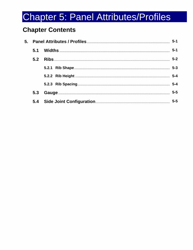
Chapter 5: Panel Attributes/Profiles Chapter Contents
5. Panel Attributes / Profiles .............................................................................. 5-1
5.1 Widths ........................................................................................................ 5-1
5.2 Ribs ............................................................................................................. 5-2
5.2.1 Rib Shape .......................................................................................... 5-3
5.2.2 Rib Height ......................................................................................... 5-4
5.2.3 Rib Spacing ....................................................................................... 5-4
5.3 Gauge ......................................................................................................... 5-5
5.4 Side Joint Configuration ...................................................................... 5-5

PANEL ATTRIBUTES / PROFILES CHAPTER 5
5. Panel Attributes / Profiles After installing several roofs and gaining a wider experience in the field of metal roofing, there will be some common panel attributes and profiles an installer encounters on a regular basis. Understanding these attributes and profiles will make the installer’s work much easier.
This chapter examines the common panel widths, ribs, gauges, and side-joint configurations that an installer is most likely to encounter working in the field.
5.1 Widths
How a panel is manufactured and installed, including the environment surrounding the installed panel, are factors that determine the width of a panel.
Before looking at these factors individually, be aware that most panels are given two different width dimensions. There is an overall width which is the actual, or formed, edge-to-edge size of the panel. The other width dimension is given as the coverage, or exposure, width. This is the width of the panel exposed to the environment. It can be thought of as the width of the panel actually seen after it is installed. It will be the smaller of the two width dimensions. The difference between the two widths is determined by the method used to install the panel and how the panel was designed. These are shown in Figures 5-1a and Figure 5-1b.
. Figure 5-1a
Formed vs. Coverage Width
Figure 5-1b Actual vs. Exposure Widths
Manufacturing Processes
Improvements in manufacturing enable panels to be made in virtually any length and significantly wider widths. Early panel dimensions were limited by the hand-tools used and by limitations of on-site brakes and formers.
Figure 5-2
Hand and On-Site Tools Limit Panel Size
Modern roll-forming equipment and the availability of larger coils of sheet metal allow larger panels to be produced. This reduces the number of panels, seams, and joints needed on a job. Longer panels lower installation costs, such as labor and materials. Fewer seams, joints, and panels also reduce the opportunities for leaks.
5-1

PANEL ATTRIBUTES / PROFILES CHAPTER 5
Figure 5-3
Large Coils of Sheet Metal Allow Larger Roof Panels to be Produced
Orientation of the Installed Panel
A panel’s installed orientation, vertical or horizontal, will be a factor in the panel’s width and how it is measured. Vertical panels (Figure 5-4, left) can have widths from 12" or less for individual standing seam panels to over 36" for a ribbed structural-style panel. For vertical panels, length is the dimension of the panel "ridge-to-eave", while width is the "rake-to-rake" dimension of the panel material. These panels will normally have some style of rib along the entire length of the panel for joining to the next panel or covering the seam. Ribs are discussed in more detail in the next section, 5.2.
Vertical Horizontal
Figure 5-4 Panel Orientation
The "width" of a horizontally-installed panel may be designated differently because of its orientation after installation (Figure 5-4). The width of a horizontally installed panel may actually be shown as the "ridge-to-eave" dimension of the panel, while the panel length is shown as the "rake-to–rake" dimension. A common width for long,
horizontally-installed panels is 12", but when a horizontally-installed metal roof panel is formed to look like other roof materials, the individual panel width can vary greatly. Modular panels representing clay tiles are 14" to 16" wide, while those looking like wood shakes may be wider, and those representing individual tiles or shingles may be much narrower, less than 12" wide.
In either case of vertical or horizontal panels, the width is considered the shorter of the two dimensions, and length as the longer.
5.2 Ribs
The main purpose of adding ribs to a panel is to strengthen it. The earliest ribs were added in the form of evenly spaced wave shapes called corrugating. These ribs were applied to the entire length and width of the panel, and made it very strong.
Manufacturing improvements, especially the roll-forming of sheet metal, enable various rib shapes, sizes, and spacing to be added.
In addition to strengthening the panel, ribs are added in order to cover panel seams, and to divert ice, snow, and water runoff. Adding ribs reduces the risk of leakage, especially between panels. Ribs of specific sizes and shapes can add to the attractiveness of a finished roof profile while providing additional ventilation as shown in Figure 5-5.
Most ribs run the entire length of a panel, although some profiles add horizontal ribs. Metal roof panel ribs are further defined by their shape, height, and spacing.
5-2

PANEL ATTRIBUTES / PROFILES CHAPTER 5
Figure 5-5
Ribbed Panels Add to a Building’s Attractiveness
5.2.1 Rib Shape
Vertical and trapezoidal ribs are the two most common shapes used on metal roof panels.
Vertical ribs are normally 90° bends along the entire length of a panel with additional, smaller bends at the top edge for sealing or interlocking with other panels. The joint may be sealed using hand or mechanical seaming tools, separate interlocking pieces, or interlocks and "snap-fit" to the next installed panel or trim piece. (Figure 5-6)
Figure 5-6 Typical Vertical Rib
Trapezoidal ribs are named after the geometric shape of the rib formed into the panel, as seen in Figure 5-7. When installed, trapezoidal ribs create open channels which provide ventilation under the finished roof, removing any moisture which may find its way beneath the roof panel.
Figure 5-7
Typical Trapezoidal Rib with Overlap Seam
A benefit of both trapezoidal panels and corrugated panels, which was mentioned earlier, is that they are nestable. One panel actually fits, or "nests" inside the others. This is shown in Figure 5-8.
These panels are easily stacked for shipping and storing. They are also convenient to manufacture and install, making them less expensive than some other panel styles.
Figure 5-8
Nested Panels
The nature of nested panel profiles both simplifies and complicates installation. On very long roofs which require more than one panel to reach from ridge to eave, the end-to-end joint is easily accomplished with what is called a "nested end lap" and is circled below in Figure 5-9.
Figure 5-9
Nested End Lap
5-3

PANEL ATTRIBUTES / PROFILES CHAPTER 5 On the other hand, most ribbed and nested panels are more difficult to flash at hips, valleys, and other diagonal terminations because of the open areas beneath the ribs. Panels of this style are often installed using exposed fasteners which are unacceptable in some applications. Always follow the manufacturer’s installation instructions for the specific style panel being installed.
Sometimes, a variation of these seams is used that incorporates a vertical rib formed on top of a trapezoidal rib. A big advantage of this seam is that the potential for leakage is reduced because the seam is further elevated above the drainage plain of the panel. This seam is shown in Figure 5-10 and is called a trapezoidal standing seam.
Figure 5-10
Example of a Trapezoidal Rib with Vertical Rib Seam Top
Smaller ribs across the pan of the panel have other names. Some are called pencil ribs. (Figure 5-11) These are small half-round, crescent-shaped ribs resembling pencils.
Figure 5-11
Vertical Rib Panel with Pencil Ribs
The shape of a rib is selected in order to match certain specifications. Specifications like panel strength, ventilation, environmental requirements or curbside appearance are all factors in a panel’s rib shape. These same
factors affect the next two rib characteristics: rib height, and rib spacing.
5.2.2 Rib Height
Rib heights vary, even within the same roof panel, for a variety of reasons. The tallest ribs are usually located at the edges along the length of the panel. The taller ribs cover any fasteners or clips used to secure the underlying panel to the substrate, as well as to provide protection from the environment since the panel beneath it also has a taller rib on its edge which needs covered.
When other ribs are added, they are usually referred to as intermediate ribs, minor ribs, pencil ribs, or similar names. These ribs, as seen in Figure 5-12, are usually not as tall, but serve to strengthen and stiffen the panel, direct runoff, and add design appeal.
Figure 5-12
Intermediate Ribbed Panel
5.2.3 Rib Spacing
Rib spacing, especially of the intermediate or minor ribs, depends on the overall width of the panel and design requirements. Ribs may be spaced evenly across the panel or in specific patterns. Some ribs may be a different shape and/or size, and appear to divide the panel in equal sections.
All ribs add to the material that is necessary to make a panel, which means added cost, but the benefits of the ribs are many. Installation is made easier because the ribs provide a convenient location to install fasteners and clips which are then covered and protected by the next panel. Panel stiffness, strength, and roof appearance are also improved. A variety of ribbed design profiles is shown in Figure 5-13.
5-4

PANEL ATTRIBUTES / PROFILES CHAPTER 5
Figure 5-13
Examples Showing the Variety of Rib Shapes, Heights, and Spacing Available on Today’s Metal
Roof Panels
5.3 Gauge
Gauge refers to the thickness of the material used to make the panel. Sheet metal thickness is traditionally measured in terms of its gauge. Gauges are given as numbers. Common sheet metal gauge numbers range from 3 to 36 - the smaller the number, the thicker the material. A metal’s gauge is also referenced to a nominal measured thickness normally stated in thousandths (.001) of an inch. For example, a 24 gauge uncoated steel panel would measure a nominal 0.0239" thick. Aluminum, however, is normally referred to by its decimal thickness and not its gauge.
A general guideline is that the thicker lower gauge material is considered the better quality panel. An installer will notice that the thicker material will handle, bend, cut, drill, and shape differently than the thinner material. However, the thicker material is usually more difficult to work.
Anyone working with metal roofing, and the variety of materials used for metal roofing, must be aware that the same gauge number does not mean the same material thickness when the materials are different. Referencing Table 5-1, 24 gauge aluminum measures a nominal 0.020" thick, while 24 gauge uncoated steel nominally measures 0.024" thick, and stainless steel, 0.025". A more complete version of this table may be found in Chapter 3.
Table 5-1
Gauge Table (in inches)
5.4 Side-Joint Configuration
The side-joint configurations on metal roof panels provide the most variety of any panel attribute. The majority of ribbed panels are joined side-to-side using a nested side-lap joint, some form of simple overlapping of the rib area, similar to that shown in Figure 5-14.
5-5

PANEL ATTRIBUTES / PROFILES CHAPTER 5
Figure 5-14
Nested Side Lap Joint
In the early days of metal roofing, side-to-side joining was accomplished by bending and folding the panel edges in the field. Depending on the number of folds, a single-lock or double-lock standing seam was formed. The difference between these two seams is shown in Figure 5-15.
Figure 5-15
Field Formed Seams
Today’s panels use several additional installation methods. Some panels are designed to interlock and just snap together. The snap-joint may be designed to cover previously installed fasteners or clamps, or require additional external fasteners to be installed, strengthening the roof system. Similar designs may snap together, but require a separate "cap" that snaps or slides into place, similar to a batten-type joint. A selection of common seam profiles is shown in Figure 5-16. Always refer to, and follow, the manufacturer’s installation instructions when working with any panel.
Figure 5-16
Common Seam Profiles
Other panels are still installed using folded seams, both single-lock and double-lock styles. The seams are field-folded, but most utilize electric seaming machines similar to the machine shown below in Figure 5-17 to roll the seam. When properly adjusted, the seamer provides a more consistent, tighter seam than a hand-formed seam.
Figure 5-17
Power Seamer of Panel Joints
A few installations are still performed using hand-forming (Figure 5-18) just as it was done centuries ago. This method is very slow, costly, and seldom used, except in historic restoration applications, small repairs, and areas inaccessible by a mechanical seamer.
©National Roofing Contractors Association
5-6

PANEL ATTRIBUTES / PROFILES CHAPTER 5
Figure 5-18
Hand Forming Panel Seams
Another side-joint configuration may be used when installing smaller unitized panels. Metal roof panels, fabricated to represent traditional shingles, shakes, and tiles, often use "fins" or flanges on several sides to interlock with panels already installed alongside, above, and below the panel being installed. Fasteners are installed along one side of the panel and covered by another panel as the installation progresses. These lap joints are clearly shown in Figures 5-19 and 5-20.
Figure 5-19 Side Lap Joint for Unitized Panels
Figure 5-20
Lap Joint with Fasteners For Unitized Panels
Notes: _____________________________________________________________________________________________________________________________________________________________________________________________________________________________________________________________________________________________________________________________________________________________________________________________________________________________________________________________________________________________________________________________________________________________________________________________________________________________________________________________________________________________________________________________________________________________________________________________________________________________________________________________________________________________________________________________________________________________________________________________________________________________________________________________________________________________________________________________________________________________________________________________________________________________________________________________________________________________________________________________________________________________________________________________________________________________________________________________________________________________________________________________________________________________________________________________________________________________________________________________________________________________________________
5-7

Chapter 6: Roof Deck Substructures Chapter Contents
6. Roof Deck Substructures ............................................................................... 6-1
6.1 Open Framing .......................................................................................... 6-2
6.2 Solid Decking .......................................................................................... 6-2
6.2.1 Wood Deck ..................................................................................... 6-3
6.2.2 Metal Deck With, or Without, Rigid Insulation ............................. 6-5

ROOF DECK SUBSTRUCTURES CHAPTER 6
6. INTRODUCTION The roof substructure is an integral part of the roof system. It lies just beneath the metal roof panels and serves two primary functions.
First, it acts as a base to which the metal roof material is attached. For metal roofs, the roof substructure secures the fasteners and clips used to hold the panel. Fasteners and clips are attached into the substructure.
Secondly, the roof substructure serves as a structural member, transferring the weight of both live and dead loads to the supporting joists or purlins. Live loads include wind, snow, rain, and moving installation equipment, including foot traffic, which a roof may encounter. Dead loads include HVAC units and the weight of the roof materials including the roof deck itself. Most decks must also act as diaphragms, transferring wind, and other lateral forces, such as seismic movement, to the building’s structural frame.
Several additional roof substructure requirements of particular interest to the installer include:
• Providing proper slope for positive drainage. A properly sloped roof should show no evidence of standing water 48 hours after it stops raining.
• As an example, limiting deck deflection to 1/240th of the total span in accommodating the designed, concentrated, or uniform load. This amounts to a deflection of 0.20" for a 300 pound load using a 4 foot span. Deflection limits for common spans are shown in Figure 6-1.
• Accommodating the movement of roof system components, such as thermal expansion and contraction of metal roof panels.
• Two major roof substructure designs are used to perform these functions and meet the requirements mentioned above.
They are referred to as open framing and solid deck substrates. Their names reflect their construction characteristics and are detailed below in Sections 6.1, Open Framing, and 6.2, Solid Decking.
Figure 6-1
Roof Deflection Limits
Installer Note An installer’s main concern with either type of substructure is the substructure surface itself. Each surface must be suitable for the application of the metal roof, and carefully inspected prior to installation. The surface should be smooth, straight, and free of humps and depressions. A solid deck should be swept and clean, free of any fasteners, litter, or debris. The roof sub-structure should be aligned vertically, square. Any surface imperfections will be transferred through the roof panel, and be visible after the roof is installed.
Joist manufacturers routinely build camber into their joists. Camber builds a curvature or "pre-stress" into the joist which "flattens" after there is a load on the joist. Camber that may be appropriate for a floor system supporting relatively heavy dead loads may not be appropriate for roof joists, which support relatively light dead loads. The "hills" and "valleys" created by camber on roof joists (especially on longer spans) may be aesthetically unacceptable and make installation more difficult. For this reason, roof joists using less, or no, camber than the manufacturer’s standard amount, are specified and used. If not confirmed, any such errors may not be visible until the roof installation has begun.
6-1

ROOF DECK SUBSTRUCTURES CHAPTER 6 6.1 Open Framing
The open frame substrate uses secondary framing members to secure the roof panels and fasteners. Commonly called purlins, bar joists, or similar names, these members may be made from wood or metal. They may be individual pieces of wood (Figure 6-2a), formed steel (Figure 6-2b), or truss-like members built from multiple individual pieces (Figure 6-2c).
Open framing must only be used with structural-style panels whose design is capable of both supporting the weight and spanning the dimensions of the open areas of the job.
Installer Note Installers must make sure the fasteners used to secure roof panels are correct for both the type of panel being used and the substrate (metal or wood) used on the job. Individual safety must be considered in every type of installation. Open framing installation involves large open areas with no support, and the risk of falling, as well as dropping materials or tools, is greatly increased. This risk applies to those working on the roof, as well as those working beneath the open spans during roof installation. Additional safety equipment may be required on open framing installations.
6.2 Solid Decking
A solid deck substrate consists of solid sheets, panels, or very closely spaced deck members to which the roof membrane is applied. The deck members may be made of wood, metal, or composite materials. Our focus in this chapter will be on decks made from wood and metal.
Solid decking must be used with non-structural style panels. Structural panels do
not require a solid deck, but may be installed over one, if desired.
Solid deck roof designs may or may not have rigid insulation included as part of the installation. Rigid insulation will be discussed later in this chapter and in more detail in Chapter 10, Roofing Design.
Figure 6-2
Common Open Framing Styles
©MBMA Metal Roofing Systems Design Manual
6-2

ROOF DECK SUBSTRUCTURES CHAPTER 6 Underlayment
Some roof deck materials require some sort of underlayment before metal roof panels are installed. Many may require both an underlayment and what is called a slip sheet. Underlayment normally comes in rolls, and is available in a variety of materials as shown in Figure 6-3. Figure 6-4 shows the most commonly used underlayment known as asphalt saturated felt or roofer’s felt.
Figure 6-3
A Variety of Underlayment Material Is Available
Underlayment provides a:
• Separation between the roofing panel and the roof deck, or substrate.
• Proper drainage path, normally to the eave, for any water that may leak under the roof panel.
• Level of secondary weather protection.
Figure 6-4
The Most Common Underlayment Is Asphalt Saturated Felt or Roofer’s Felt
Underlayment material needs to be supported, and is not used on open framing roof systems.
Most underlayment material is either asphalt, synthetic, or polymer-based. This material tends to grab and stick to a roof’s metal panel causing the underlayment to stretch and tear as the panel thermally expands and contracts. Once stretched and torn, the underlayment fails to provide protection to the roof structure. Therefore, some applications may require a slip sheet to be installed on top of the underlayment. A slip sheet provides a surface between the underlayment and the roof panel that allows the roof panel to freely expand and contract without sticking to the underlayment. The slip sheet can be clearly seen in Figure 6-5.
Figure 6-5
A Slip Sheet Is Often Installed Between the Underlayment and the Roof Panel.
If underlayment and slip sheets are used, they should be inspected for proper installation and damage before installing the roof panels. The underlayment and slip sheet can be easily damaged by careless sliding of material, dropped tools, and installer carelessness during panel installation. Installation details will be covered in Chapter 10, Roof Designs.
6.2.1 Wood Deck
Wood is a versatile material often used for construction of a solid roof deck. Plywood,
6-3

ROOF DECK SUBSTRUCTURES CHAPTER 6 oriented stranded board (OSB), and individual wood planks are different forms that are used as solid roof decks.
Plywood
Plywood is popular for both residential and commercial decking, like the deck in Figure 6-6. All roof deck plywood should be American Plywood Association (APA) rated sheathing.
Figure 6-6
A Plywood Solid Roof Deck Substrate
Most building codes require a label on wood panels, ensuring compliance with the standards set by the Department of Commerce,1 or the American Plywood Association.2 It is recommended that wood panels bear the APA trademark and have a smooth surface upon which to install the roof panel. Two different plywood stamps are shown in Figures 6-7a and 6-7b.
1 Standard PS 1-83, all veneer plywood 2 Performance Standard PRP-108
Figure 6-7a
Plywood Stamp Conforming To Department Of Commerce Standard PS 1-83
Figure 6-7b
Plywood Stamp Conforming To APA Performance Standard PRP-108
The span rating is of particular interest to anyone making a panel repair or replacement. Both examples in Figure 6-7 are rated 32/16. The left-hand number (32) indicates the maximum center-to-center spacing of supports, in inches, when the panels are installed with the long dimension running across the supports. The right-hand number (16) indicates maximum center-to-center spacing of supports, in inches, when the panels are used as sub-flooring in a double flooring application. In both applications, it is assumed that the panels are continuous and extend over two or more spans.
6-4

ROOF DECK SUBSTRUCTURES CHAPTER 6 The minimum thickness of any plywood panel used in a roofing application should be a nominal 15/32", end joints should be staggered, and the correct fasteners should be used for the installation design requirements.
Oriented Strand Board (OSB)
Like plywood, OSB is often used in both residential and commercial applications. Oriented Strand Board is made from rectangular-shaped wood strands which are cross-oriented, compressed, and glued together with waterproof glues. The cross-oriented construction gives OSB material added strength and rigidity in both directions. Any OSB used for roof decking should be APA rated sheathing, and have a minimum thickness of 15/32".
Wood Plank Decks
Individual plank roof decks are typically used where their appearance from inside the building is a primary consideration. The boards may be solid lumber or laminated boards. Solid wood boards may have square edges, ship-lapped ends, or tongue and groove edges for installation. Laminated boards often have a tongue and groove edge for installation.
Wood plank decks should have a minimum thickness of one inch. Fastener type and spacing are determined by the design requirements of the individual installation. Any repair or replacement of a wood plank deck should match the original material, fasteners, and fastening pattern as closely as possible. Any variation may affect the deck strength and be visible through the installed metal roof panel.
6.2.2 Metal Deck With, or Without, Rigid Insulation
A solid metal roof deck is constructed from individual formed steel panels. These panels have formed ribs for strength and rigidity.
Various rib profiles and sheet gauges are available and are selected to match the design requirements of the roof. Three common profiles are shown in Figures 6-8a, 6-8b, and 6-8c.
Figure 6-8a
Narrow Ribs
Figure 6-8b
Intermediate Ribs
Figure 6-8c
Wide Ribs
Common Metal Roof Deck Rib Profiles Most recommendations call for a minimum gauge of 22 and a G90 galvanized coating. Metal deck material may be fastened to the support structure by welding where a metal structure is used, or by mechanical fasteners. Weld spacing, fastener type, and spacing are based on the design requirements of the roof and will vary. Welding and metal deck installation also has additional safety and health precautions depending on methods and materials used. Always read and follow applicable warnings, cautions, and advisories.
Figure 6-8 Common Rib Profiles
6-5

ROOF DECK SUBSTRUCTURES CHAPTER 6 Rigid Insulation
Rigid insulation is often installed as part of the roof installation. A properly insulated building uses less energy in both heating and cooling. However, insulation does not provide a suitable fastening surface for fasteners; therefore, several methods are used to provide panel support.
Roof panel clips and bearing plates may be used on top of the insulation as shown in Figure 6-9. Note the metal bearing plate on top of the insulation which provides a solid surface for the clip.
Figure 6-9
Rigid Insulation Using Bearing Plates
Another method uses steel z-shaped purlins between the insulated panels. Figure 6-10 shows how these z-purlins provide a solid surface for fastening the panel clips and fasteners.
Figure 6-10
Rigid Insulation Using Z Purlins
One method of installing rigid insulation uses purlins or battens between the sheets of insulation. This provides a consistent surface for panel installation.
In summary, the roof deck is the structure to which the metal roof panels are attached. Understanding roof decks is an important key in the proper installation of a metal roof. The type and style of the roof deck will affect fastener selection and spacing, and determine additional steps that an installer may need to perform in order to properly install the roof. Additional items, like underlayment, slip sheets, or insulation, directly affect how an installer performs the work and what specific items to check before roof installation can begin.
Notes: _______________________________________________________________________________________________________________________________________________________________________________________________________________________________________________________________________________________________________________________________________________________________________________________________________________________________________________________________________
©MBMA Metal Roofing Systems Design Manual
6-6

Chapter 7: Panel Connections Chapter Contents
7. Introduction ........................................................................................................ 7-1
7.1 Wind Effects ................................................................................................ 7-1
7.2 Water Shedding ........................................................................................... 7-1
7.3 Sealants ....................................................................................................... 7-2
7.4 Seismic and Later Movement Effects ........................................................ 7-2
7.5 Thermal Effects ........................................................................................... 7-3
7.6 Snow and Ice Effects .................................................................................. 7-3
7.7 Side Joint Configurations ........................................................................... 7-4
7.8 Mechanically Seamed ................................................................................. 7-6

PANEL CONNECTIONS CHAPTER 7
7. INTRODUCTION
The panel connections are "what keep the roof on the roof." When the proper tools and materials are used, the installer is the most critical factor of the installation. Knowledge of various panel connections, and understanding the reasons why certain fasteners, tools, or materials are used, will enable the installer to deliver a roof system that performs as one unit.
Panel connections not only secure the roof during normal use, but are designed to withstand any "worst case" situations involving the wind and weather, seismic activity, thermal effects, and roof loading. A brief look at these issues now will lay a foundation for understanding. These topics are detailed in later chapters, especially Chapter 10, Roofing Design; Chapter 13, Sealants; and Chapter 14, Fasteners.
7.1 Wind Effects
As air flows across the roof, the metal panels making up the roof surface act like an airplane wing. This creates a "lift" or suction force. During periods of moderate or high winds, this effect becomes quite exaggerated, and the entire roof can be lifted, or "sucked," off the structure as shown in Figure 7-1. The frequency and strength of the panel connections is vital to roof survival during a wind storm.
Table 7-1
Metal Roof Damage Due to Wind Effect
Panels are attached with either exposed or concealed fasteners. Installing ribbed panels with exposed fasteners involves directly fastening the panel to the deck. This attachment method provides increased wind protection, but has the obvious disadvantage of penetrating the panel.
Concealed fasteners, or clips, do not penetrate the panel. Instead, they are installed along the outside edges of the panel. However, during high winds, the center of the panel remains unsecured, and may flex as lift is developed. This flexing stresses the panel, rotating the seam, which may deform the panel and clip, and cause the joint to fail. Panel clips are unique and designed specifically for certain panels. They will only function properly when installed using the specific fastener and panel for which they were designed. Always check with the manufacturer for the proper installation information.
7.2 Water Shedding
The primary function of a roof is to shed water and protect the shelter from the environment. The metal panels making up the roof surface can only leak at the seams, where there is a puncture, or where an opening has been cut into the panel. A panel’s joint configuration, fasteners, and sealant (when used) are key factors in a leak-proof installation.
Properly installed fasteners (Figure 7-2) are necessary in order to provide and maintain a tight seam capable of shedding water. Any exposed fastener that is not completely secured, is crooked, or has a defective seal will eventually leak. Common fastener faults, as shown in Figure 7-3, are caused by an installer under or over-driving the fastener while securing the roof panel.
7-1

PANEL CONNECTIONS CHAPTER 7
Figure 7-2 Properly Installed Fasteners Provide
Strong Leak-Proof Panel Connections
Figure 7-3
Under or Over-Driven Fasteners Will Eventually Leak
Wherever there are overlapping surfaces, there is the possibility of leakage due to what is called "capillary action." Water will be drawn up into the small gap where the two surfaces overlap. To prevent this capillary seepage, many panels have an additional ridge formed into the rib which will cover a seam. This additional ridge, circled in Figure 7-4, "breaks" the adhesion of any water trying to seep back between the panels and provides a drain to the outside.
Figure 7-4
Additional Groove Prevents Capillary Leakage
7.3 Sealants
Many panel connections require the use of a sealant. When using a sealant always:
• Select the correct type of sealant.
• Apply the correct amount of sealant.
• Position sealant in the correct location.
• Check the expiration date of the sealant.
For more details on sealants, refer to Chapter 13
7.4 Seismic and Lateral Movement Effects
A properly designed roof must also adjust to lateral, or side to side, movement and stress. The forces from this type of stress are illustrated in Figure 7-5.
Figure 7-5 Direction of Forces During Lateral Panel Stress
Most ribbed panels are designed to "flex", or adjust to small amounts of lateral movement through their formed ribs. Figure 7-6 illustrates a variety of ribbed panels. These ribs will "flex" during lateral movement of the panel, preventing damage and distortion. Other roof systems accommodate these stresses through parts of the roof system other than the panel connection.
7-2

PANEL CONNECTIONS CHAPTER 7
Figure 7-6 These Rib Profiles Will "Flex" During Lateral
Stresses
It is important that the manufacturer’s instructions are followed carefully so that if, and when, the roof experiences such stresses, the roof system performs as designed.
7.5 Thermal Effects
Metal expands and contracts as temperature changes. Metal roof panels, by the nature of their material, size, and the extreme temperature changes that take place, may experience significant size changes on a regular basis. (Figure 7-7) This is normal.
Figure 7-7
Temperature Extremes Are Normal for Any Roof
The expansion and contraction of the panels must be taken into consideration and addressed during the design and installation of the roof. A detailed look at this issue is covered in Chapter 10, Roofing Design, but the installer needs to always remember the following general truths:
• All material expands and contracts as temperature changes.
• Different metals have different amounts of change for the same amount of temperature (see Table 7-1).
Table 7-1
Thermal Expansion of Common Roof Metals
• The following relationships always apply: o As temperature , length
o As temperature , length
o As length of panel ,amount of change
o As length of panel ,amount of change
The direct fastening method does not account for this change in panel size, while most concealed fasteners provide for thermal movement through several clip configurations. Clip examples are shown in Figures 7-16 and 7-17, are discussed in the next section, 7.1, and detailed within Chapter 14, Fasteners.
7.6 Snow and Ice Effects
In some areas, the effect of possible snow and ice accumulation on a metal roof, as shown in Figure 7-8, requires that additional attention be given to the panel connection during Installation.
7-3

PANEL CONNECTIONS CHAPTER 7
Figure 7-8 Possible Snow and Ice Effects Require
Special Attention During Installation
The weight of the snow and ice accumulation acts as a gravity load, sometimes called a "drag load." This weight tends to grab the panel and attempts to slide, or drag, the panel out of place. The amount of force is a function of the snow load, panel length, and roof shape.
When a panel is installed using clips which adjust to panel movement due to thermal conditions, it is also necessary to secure, or "pin" the panel at some point along its length so it does not migrate out of its intended location. An example of damage caused by this type of panel migration can be seen below in Figure 7-9.
Figure 7-9
Adverse Effects of Snow Load on a Metal Roof
Depending on the roof design, metal panels are pinned at the ridge, eave, or midpoint of the panel. It is important that the panel be pinned at only one point, in order to accommodate thermal expansion. This "point of fixity," plus additional snow and ice
considerations are detailed in Chapter 10, Roofing Designs.
7.7 Side Joint Configurations
In addition to the previous considerations, there are other factors closely related to the installation of the roof which affect the exact type and style of the side joint configuration selected for the roof panel.
As mentioned in Chapter 4, low slope roofs are designed with hydrostatic joints; capable of sustaining slow-moving water (Figure 7-10).
Figure 7-10
Low Slope Roofs Must Handle Slow Moving Water
Steep sloped metal roof panels (Figure 7-11) may be designed with hydrokinetic joints; capable of sustaining fast-moving water for periods of time. Each of these slopes requires different design features and unique profiles.
Figure 7-11 Steep Slope Roofs Must Handle
Fast Moving Water Runoff
7-4

PANEL CONNECTIONS CHAPTER 7 Exposed or concealed fastener panels have side configurations designed for the type of fastener required.
Panels installed using exposed fasteners often have simple overlap or side-lap type joints. Depending on design requirements, the same panel may require fasteners to be installed on the top of a rib or ridge, while another roof design requires the fasteners to be installed on the pan, or flat valley, portion of the panel. These different fastener patterns are shown in Figures 7-12 and 7-13.
Figure 7-12 Exposed Fasteners Installed at Top of Ribs
Figure 7-13 Exposed Fasteners Installed on the Pan
Panels installed using concealed fasteners or clips, often have larger side ribs already formed in the panel. These larger ribs cover the fasteners or clips securing the previously installed panel. (Figure 7-14)
Figure 7-14
Larger Side Ribs Are Used To Conceal Panel Fasteners
Some panels, though, are designed to use separate fastener covers. These panels will have side-joints configured to accept and lock the separate cover when it is snapped into place. Although similar to a batten-type seam, many varieties and styles of this seam exist. Two examples are illustrated in Figure 7-15.
Figure 7-15
Separate Fastener Covers Snap and Lock Into Place
The simple one-piece clip design shown in Figure 7-16 allows the panel to adjust to thermal movement yet remain firmly attached to the substrate.
Figure 7-16 Basic One-Piece Clip,
the Panel Moves Under the Clip
However, if a sealant is used on the seam joint, the panel often tears the sealant as it tries to slide along, under the clip, to adjust to thermal differences. In this case, a two-piece clip similar to Figure 7-17 is used to allow use of sealant and still permit thermal movement of the panel.
Thermal Movement
© Rob Haddock, all rights reserved
7-5
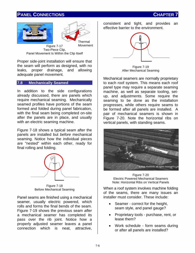
PANEL CONNECTIONS CHAPTER 7
Figure 7-17
Two-Piece Clip, Panel Movement Is Within the Clip Itself
Proper side-joint installation will ensure that the seam will perform as designed, with no leaks, proper drainage, and allowing adequate panel movement.
7.8 Mechanically Seamed
In addition to the side configurations already discussed, there are panels which require mechanical seaming. Mechanically seamed profiles have portions of the seam formed and folded during panel fabrication, with the final seam being completed on-site after the panels are in place, and usually with an electric seaming machine.
Figure 7-18 shows a typical seam after the panels are installed but before mechanical seaming. Notice how the individual pieces are "nested" within each other, ready for final rolling and folding.
Figure 7-18
Before Mechanical Seaming
Panel seams are finished using a mechanical seamer, usually electric powered, which rolls and forms the final bends of the seam. Figure 7-19 shows the previous seam after a mechanical seamer has completed its pass over the rib joint. Notice how a properly adjusted seamer leaves a panel connection which is neat, attractive,
consistent and tight, and provides an effective barrier to the environment.
Figure 7-19
After Mechanical Seaming
Mechanical seamers are normally proprietary to each roof system. This means each roof panel type may require a separate seaming machine, as well as separate tooling, set-up, and adjustments. Some require the seaming to be done as the installation progresses, while others require seams to be formed after all panels are installed. A pair of mechanical seamers is shown in Figure 7-20. Note the horizontal ribs on vertical panels, with standing seams.
Figure 7-20
Electric Powered Mechanical Seamers Note: Horizontal Ribs on Vertical Panels
When a roof system involves machine folding of the seams, there are many issues an installer must consider. These include:
• Seamer - correct for the height, seam style, and panel gauge?
• Proprietary tools - purchase, rent, or lease them?
• Work schedule - form seams during or after all panels are installed?
Thermal Movement
© R
ob H
addo
ck,
all r
ight
s re
serv
ed
© Rob Haddock, all rights reserved
7-6

PANEL CONNECTIONS CHAPTER 7 • Will the tool fit on seams located
along walls and roof accessories? These issues, and others relating to mechanical seamers, are detailed in Chapter 12, Tools and Field Operations, Section 12.1.9, Seaming Tool.
Remember, the panel connection is only one member of the metal roof family of products. It is one link in the roof system chain. Selecting the proper materials and fasteners, using the proper panel connections, and performing the proper installation method will prevent the panel connection from being the weakest link.
Notes: _____________________________________________________________________________________________________________________________________________________________________________________________________________________________________________________________________________________________________________________________________________________________________________________________________________________________________________________________________________________________________________________________________________________________________________________________________________________________________________________________________________________________________________________________________________________________________________________________________________________________________________________________________________________________________________________________________________________________________________________________________________________________________________________________________________________________________________________________
________________________________________________________________________________________________________________________________________________________________________________________________________________________________________________________________________________________________________________________________________________________________________________________________________________________________________________________________________________________________________________________________________________________________________________________________________________________________________________________________________________________________________________________________________________________________________________________________________________________________________________________________________________________________________________________________________________________________________________________________________________________________________________________________________________________________________________________________________________________________________________________________________________________________________________________________________________________________________________________________________________________________________________________________________________________________________________________________________________________________________________________________________________________________________________________________________________________________________________________________________________________________________________________________________________
7-7

Chapter 8: Common Panel Accessories Chapter Contents
8. Introduction ...................................................................................................... 8-1
8.1 Ridge Vents – Types and Applications......................................... 8-1
8.1.1 Ridge Vents .................................................................................. 8-1
8.1.2 Gable Vents .................................................................................. 8-2
8.1.3 Soffit and Drip Edge Vents .......................................................... 8-2
8.1.4 Round Gravity Vents ................................................................... 8-3
8.1.5 Power Vents ................................................................................. 8-3
8.2 Roof Curbs – Types and Applications .......................................... 8-3
8.2.1 Pre-manufactured and Field Manufactured ............................... 8-4
8.3 Roof Jacks .............................................................................................. 8-6
8.4 Skylights ................................................................................................. 8-7
8.5 Snow Guards – Types and Applications ...................................... 8-8
8.6 Closures .................................................................................................. 8-11
8.6.1 Eave .............................................................................................. 8-11
8.6.2 Ridge ............................................................................................. 8-12
8.6.3 Side / Gable .................................................................................. 8-12
8.7 Lightning Protection ........................................................................... 8-13
8.8 Solar and Photovoltaic Systems ..................................................... 8-14

COMMON PANEL ACCESSORIES CHAPTER 8
8. INTRODUCTION
Common roof accessories include items like roof vents, curbs and jacks, access hatches, skylights, and snow guards. These items are not necessarily provided by the roofing system manufacturer. Some of these items may be ordered and shipped to the site from other manufacturers, while others may be made locally, even on-site. Depending on the accessory, and the specifics of the job, the installer may be directly involved in the installation of the accessory. In other cases, the accessories, or portions of them, are installed by other tradesmen, but still require the roofing installer to install the roof itself, flashing, and/or trim.
Installer Note
Accessory items may, or may not, be included in a roof manufacturer’s warranty. The manufacturer should be contacted concerning the installation of any accessory, its possible effect on the roof warranty, and further installation details of the accessory.
8.1 Roof Vents – Types and Applications
Proper ventilation is a critical factor affecting both a roof’s efficiency and its longevity. In this section, common vent types and typical component applications will be discussed. Ventilation principles and concepts, along with roof ventilation system issues are covered in Chapter 10, Roofing Design, and Section 10.3.2, Ventilation.
Installer Note
Ventilation components like those shown in this section will be part of the roof ventilation system and installation; however, additional ventilation components may be found during a roof installation and need to be addressed. These additional ventilation accessories may be part of other, separate, ventilation systems. These systems may include, but are not limited to, HVAC, welding, and paint systems.
8.1.1 Ridge Vents
Heat rises, and unless directed elsewhere, will attempt to rise to the highest point within the structure, generally the roof ridge. Proper ventilation at this point in the roof system is important. The installer’s skill when installing the correct components in this area is critical in order to avoid problems after the installation.
Most metal roof designs incorporate one of two commonly used ridge vent styles: a low profile ridge vent or a standard ridge vent. Keep in mind that although ridge vent styles are similar, each manufacturer often designs ridge-venting components specific to the panels being installed. These special components often have their own unique installation instructions and requirements.
Low-profile ridge vents are commonly used with architectural-style roofs. They are designed to blend in with the rest of the roof color, shape, and style. Low-profile vents are mostly used in "attic" installations and are normally considered part of the roof venting system. They are installed in conjunction with the rest of the ridge closures and components on a roof installation.
8-1

COMMON PANEL ACCESSORIES CHAPTER 8
Figure 8-1
A Low-Profile Ridge Vent Blends In with the Rest of the Roof Profile
Standard ridge vents, like the one seen in Figure 8-2, have throat sizes of 9 or 12 inches, and a standard length of 10 feet. They are common roof vents for industrial applications. Standard ridge vents are considered part of the "whole building" ventilation system and are used in conjunction with wall louvers, wall fans, and other components. They allow significant amounts of hot air to escape and are often equipped with operating dampers which allow adjustment for seasonal temperature changes.
Figure 8-2
Standard Ridge Vent
Technically not ridge vents, but located near the roof ridge and similar in operation, are individual static vents. Static vents, as shown in Figure 8-3, are smaller than ridge vents, incorporate a low-profile style, and often are colored to match the roof panels.
Figure 8-3
Static Roof Vents and Typical Locations
8.1.2 Gable Vents
Gable vents, like the one shown in Figure 8-4, can function as an intake or an exhaust vent. When used without additional intake vents at the roof's low points, it will function as an intake or an exhaust vent, depending on the wind direction. The effectiveness of the gable-end roof vent is dependent on both the wind speed and direction. The vent
Figure 8-4
Gable Roof Vent
Is most effective with winds of sufficient speeds and from a direction perpendicular to the gable vent. The least effective vent operation results from light winds coming from a direction which is parallel to the vent itself. The size of the gable vent is dependent of the ventilation requirements for the roof installation.
8.1.3 Soffit and Drip Edge Vents
Soffit and drip edge vents are considered part of the roof vent system and function as intake vents rather than exhaust vents. They are designed to bring in cooler, outside air as the warmer exhaust air leaves the structure. Figure 8-5 illustrates several common vent designs. The most
©National Roofing Contractors Association
©National Roofing Contractors Association
8-2

COMMON PANEL ACCESSORIES CHAPTER 8 common formats are continuous soffit panels with pre-formed vent openings; individually installed soffit vents, or pre-formed metal closure and trim pieces with pre-formed vent openings already molded into the piece. It is normal for each panel manufacturer to offer vent panels and trim pieces designed specifically to blend and match the exact roof panels being installed.
Figure 8-5
Soffit and Drip Edge Vents
The number and type of intake vents required to properly vent the roof will vary depending on the roof design and the system requirements. It is important, however, to properly install all vents in order to prevent precipitation, animals, and insects from entering through the vent.
8.1.4 Round Gravity Vents
Similar to the standard ridge vent, except round in shape, round gravity vents are unpowered, yet allow rising heat to freely escape. Made from 26 to 22 gauge steel, depending on the size, which ranges from 12" to 20" in diameter, round gravity vents can be used as either "whole building" or attic vents. Mounted on the roof slope, near the ridge, these unpowered vents also incorporate operating dampers for seasonal temperature changes.
Figure 8-6
Round Gravity Vent
8.1.5 Power Vents
When the project specifications require precise air movement and control, a power vent is normally used. While fabricated from steel, aluminum, or a combination of the two materials, power vents are available in a wide variety of throat and motor sizes. Power vents are capable of adjusting exhaust air flow to meet any changes within the structure or the environment. Power vents are often similar in size and appearance to the previously described types of roof vents with the only difference being the power vent's internal motor and control circuitries.
8.2 Roof Curbs – Types and Applications
Roof curbs are raised members used to support roof penetrations such as skylights, mechanical equipment, and roof hatches. The curb raises the penetration connection above the level of the roof surface, reducing the possibility of leakage. Curbs also provide improved, and level (if necessary), surfaces for attachment of additional roof accessories.
Depending on the design requirements, a curb may be a 1 or 2-piece unit as shown in Figure 8-7, or a multi-piece unit with or without a separate, structural framework.
©National Roofing Contractors Association
©National Roofing Contractors Association
8-3

COMMON PANEL ACCESSORIES CHAPTER 8
(a) - One-Piece Curb
(b) - Two-Piece Curb
Figure 8-7 One and Two-Piece Roof Curbs
Two piece curbs are generally used in retrofit applications where existing penetrations, such as chimneys or roof mounted equipment, cannot be removed and must be flashed around to provide a weathertight condition. Rooftop units that exceed the maximum weight requirements for single curbs will require a structural curb surrounded by a one or two-piece flashing curb attached to the roof system. Framing for this structural curb is not considered part of the roof system.
8.2.1 Pre-manufactured and Field Manufactured
Curbs present obstacles to the designed flow and drainage of the roof, but a properly designed curb as shown in Figure 8-8 will divert runoff and roof drainage around the curb. This is accomplished by having small crickets, diverters, or saddles, formed as an integral part of the curb structure. A large variety of roof curbs are available as standard accessories, but curbs can also be custom-made for a particular installation.
Figure 8-8
A Properly Designed and Installed Curb Note Cricket and Drainage Clearances
Any curb installation will involve the installer. Responsibility for the curb installation may belong of other tradesmen, a joint effort between various trades, or the entire responsibility of the roofing team. Another point to remember is that curbs are an item that may be installed after the roof has been installed, or even in-service for a period of time. If the curb is not installed correctly, like the curbs pictured in Figure 8-9, sooner or later the roof will leak, and the customer may try to blame the initial roofing installer. Although not their fault, the roofing team will be expected to provide solutions to the problem. Figure 8-9 shows curbs that do not allow for good water drainage and are not properly sealed to the roof.
Figure 8-9
Improper Curb Types
Curbs are installed in an "over-over," "over-under," or "under-under" configuration in relationship to the roof panels. This relationship is illustrated in Figure 8-10. The metal roof system manufacturer should
8-4

COMMON PANEL ACCESSORIES CHAPTER 8 always be contacted concerning the use of roof curbs. Some manufacturers offer curbs exactly matching the roof panel profile, simplifying installation and flashing. The manufacturer may also provide recommended curb suppliers. Using a recommended supplier helps avoid warranty issues while ensuring system compatibility.
Figure 8-10
The Curb – Panel Relationship
The previously mentioned types of roof curbs may also be divided into two groups based on their installed location. Some curbs are exact location curbs, while others are field-located curbs.
Exact location curbs are customized to fit at an exact location on the roof system. Because the curb must be located in an "exact" location, the roof installer may have to reconsider roof panel layouts in order to reduce the risk of leaks, and simplify trimming around the curb. The roof installer will need to coordinate the installation with the other trades involved to ensure that the penetrations have been properly located and sized to fit the curbs. This customized type of curb requires additional lead times, precise coordination of the trades, and increases the overall cost of the system.
Field-located curbs are manufactured to be installed without the need for locating the
exact curb location prior to panel installation. This type of curb is more common, especially since it has the benefits of shorter lead times and lower cost, but may not be suitable in every situation.
Figure 8-11
Roof Curb Locations May Be Exact Location or Field-Located
There are several things an installer should consideration in order to provide the best possible curb installation. Whenever possible, an installer should:
• Use curbs made from aluminum or stainless steel
• Use under/over curbs
• Use the following clearances: o Minimum 12" between panel end
and diverter on the upslope o Minimum 6" between the curb sides
and panel seams
• Use rib-to-rib curbs
Following these considerations, as shown in Figure 8-12, will provide an installation that will appear neat, perform as expected, and install in the easiest manner.
©MBMA Metal Roofing Systems Design Manual
8-5
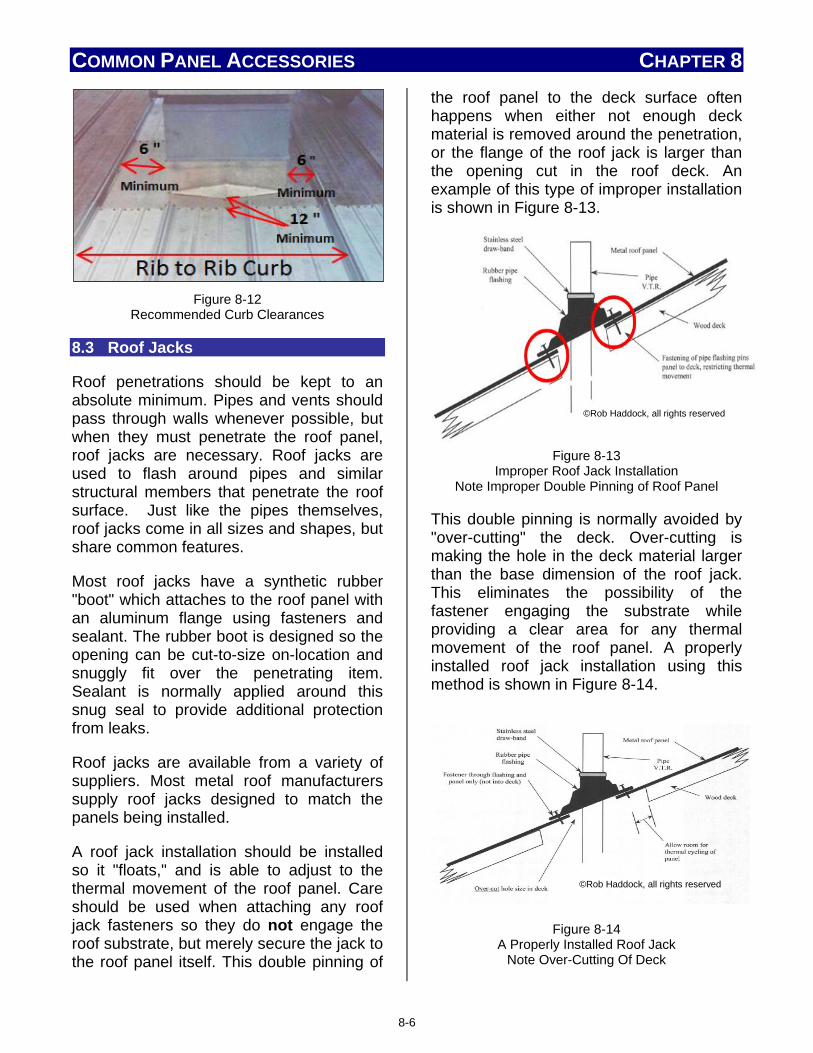
COMMON PANEL ACCESSORIES CHAPTER 8
Figure 8-12
Recommended Curb Clearances
8.3 Roof Jacks
Roof penetrations should be kept to an absolute minimum. Pipes and vents should pass through walls whenever possible, but when they must penetrate the roof panel, roof jacks are necessary. Roof jacks are used to flash around pipes and similar structural members that penetrate the roof surface. Just like the pipes themselves, roof jacks come in all sizes and shapes, but share common features.
Most roof jacks have a synthetic rubber "boot" which attaches to the roof panel with an aluminum flange using fasteners and sealant. The rubber boot is designed so the opening can be cut-to-size on-location and snuggly fit over the penetrating item. Sealant is normally applied around this snug seal to provide additional protection from leaks.
Roof jacks are available from a variety of suppliers. Most metal roof manufacturers supply roof jacks designed to match the panels being installed.
A roof jack installation should be installed so it "floats," and is able to adjust to the thermal movement of the roof panel. Care should be used when attaching any roof jack fasteners so they do not engage the roof substrate, but merely secure the jack to the roof panel itself. This double pinning of
the roof panel to the deck surface often happens when either not enough deck material is removed around the penetration, or the flange of the roof jack is larger than the opening cut in the roof deck. An example of this type of improper installation is shown in Figure 8-13.
Figure 8-13
Improper Roof Jack Installation Note Improper Double Pinning of Roof Panel
This double pinning is normally avoided by "over-cutting" the deck. Over-cutting is making the hole in the deck material larger than the base dimension of the roof jack. This eliminates the possibility of the fastener engaging the substrate while providing a clear area for any thermal movement of the roof panel. A properly installed roof jack installation using this method is shown in Figure 8-14.
Figure 8-14 A Properly Installed Roof Jack
Note Over-Cutting Of Deck
©Rob Haddock, all rights reserved
©Rob Haddock, all rights reserved
8-6

COMMON PANEL ACCESSORIES CHAPTER 8 The accessories that an installer chooses to use should always be of the highest quality. Metal roofs are designed and warranted to last for many years - sometimes up to 40 years or more. If a roof jack that is designed to last only 10 years is used on a long-term roof, it will fail and leak. This failure could be perceived as a roof failure and result in a loss of goodwill and possible litigation. This same reasoning should apply to any accessories an installer uses, including panel fasteners and sealants.
As noted in the discussion of roof curbs, roof jacks may also be installed long after the roof, and may have been installed by members of another trade.
Figure 8-15
Incorrect Roof Jack Installation by Other Tradesmen
Two incorrect roof jack installations are shown in Figure 8-15. These were installed by members of other trades who failed to properly consider the risk of roof leakage after installation. The photo on the left in Figure 8-15 shows a penetration through the panel seam. The photo on the right shows a conduit and gas line in one pipe jack. Any failure of a roof jack will probably result in a call to the roofing contractor who initially installed the roof.
8.4 Skylights
Skylights allow natural light to enter a building, providing both aesthetic appeal
and cost savings in lighting. These benefits have resulted in a growth in skylight use in both residential and non-residential applications. (See Figure 8-16) Skylights can be insulated, non-insulated, or glazed. Skylights can also be curb-mounted or mounted directly on the roof.
Figure 8-16
Typical Skylight Application
Additionally, many panel manufacturers offer translucent roof panels like the one shown in Figure 8-17. These panels have identical profiles to a normal metal panel. During the roof installation, these translucent panels are installed in the place of a normal metal panel allowing light to enter the structure.
Figure 8-17
Translucent Skylight Roof Panel
Skylight materials may have different coefficients of thermal expansion from metal trim and roof panels. They often move more than metal panels. It is advised that any fastener hole in the skylight used to fasten the skylight to a metal panel, be
8-7

COMMON PANEL ACCESSORIES CHAPTER 8 oversized by 1/16" to allow for some differential movement.
SAFETY NOTE
An installer must remember one rule around any type of skylight.
Skylights ARE NOT a safe walking surface and should be protected from foot traffic.
Always ensure that the installation and use of all skylight panels comply with State, Federal, and OSHA regulations and laws, including, but not limited to, guarding all light transmitting panels with screens, fixed standard railings, or other acceptable safety controls that prevent fall-through.
An installer's involvement with skylight installation may vary, but will certainly include trim and flashing around the penetration. It is important to remember that most installed curbs are designed to "float" in order to adjust to thermal changes within the roof system. The roof system manufacturer's instructions should be consulted to make sure the correct material and methods, specific to the panels being installed, are used.
8.5 Snow Guards – Types and Applications
Depending on the geographic location of the installation and climate considerations,
the issues created by snow and ice may need to be addressed. Snow guards are used to minimize the potential for snow to slide off a roof, particularly in areas where it may pose a threat to pedestrian or vehicle traffic. Snow guards are also commonly used to prevent migration of snow into valley areas and other critical flashing conditions such as roof penetrations. The accumulated snow release can cause personal injury; property, structural and roof damage; and in extreme cases, even death.
Figure 8-18
The Sudden Release of Accumulated Roof Snow
Snow guards help to prevent the sudden release of accumulated snow so that it evacuates the roof in a more controlled fashion. Snow guards are of two types: individual “cleats” or continuous, horizontal bars or “fences”. Snow guards of minimal height dimensions can be successful at restraining snow banks of many feet in depth. Examples of these types of snow guards are pictured in Figures 8-19, 8-20, and 8-22.
Whichever method is used to install snow guards, read and follow the installation instructions carefully. Improper installation could cause the snow guard to fail. Before installing any snow guard, the roof manufacturer should be contacted to make sure the addition of the snow guards will not change the panel installation requirements or void any warranty.
©Rob Haddock, all rights reserved
8-8

COMMON PANEL ACCESSORIES CHAPTER 8
Figure 8-19
Individually -Mounted Snow Guards Come In a Variety of Styles and Attachment Methods
Figure 8-20
A Snow Fence Type Clamp Attached to Standing Seams
Figure 8-21
Electrical Ice Melt System Installed Along the Fascia Avoids Penetration of the Roof Surface
Snow guards are commonly made from either plastic or non-corrosive metals. If a
metal snow guard is used it should be compatible with the metal roof material. Aluminum is compatible with most metal roofs, except for copper. 300 series stainless steel alloys are compatible with all roof materials. Snow guards are commercially available that attach to the roof with fasteners (mechanical bond) or adhesives (chemical bond). When a snow guard is adhered to a painted surface the ultimate strength of the bond may be determined by the strength of the paint’s adhesion to the metal. Other snow guards are mechanically installed, either by directly fastening through the roof panel, or by clamps secured to the raised seams of the panels.
Before installing any snow guard, the roof manufacturer should be contacted to make sure the addition of the snow guards will not change the panel installation requirements or void any warranty.
While snow guards that are installed using fasteners drilled through the panel into the substrate may provide a substantial mechanical bond, this method also punctures the panel, creating the possibility of leaks. When mechanically fastened snow guards are used the thermal movement of the metal roof system must be maintained. Do not over-tighten the fasteners, or damage to the snow guard and roof surface may occur.
For standing seam type roofs, snow guards that are installed using mechanical, non-penetrating methods are preferred. A wide variety of "seam-mounted" clamping devices are currently available. They generally follow the basic steps illustrated in Figure 8-22. It is critical to the proper and safe installation of this type of fastener that
©Rob Haddock, all rights reserved
©Rob Haddock, all rights reserved
8-9

COMMON PANEL ACCESSORIES CHAPTER 8 the set screws are torqued to the proper value. The correct value is determined by factors such as gauge thickness of the panel, snow loading, clamp size, etc. The snow guard clamp manufacturer should be consulted for the correct torque value to be used for the installation.
Figure 8-22
Example of Seam Mounted Fence System
Whichever method is used to install snow guards, read and follow the installation instructions carefully. Improper installation may cause the snow guard to fail. This may result in injury and damage, including to the roof system itself. A number of causes can lead to failure of snow guards adhered to a painted surface as seen in Figure 8-23. The roof damage shown in Figure 8-24 was caused by improper installation.
Figure 8-23
Failure of adhesive applied snow retention devices due to inadequate quantity, or design of system, or
improper adhesive type, or bonding failure
Figure 8-24
Roof Damage from Improper Installation
Before installing any snow guard, the roof manufacturer should be contacted to seek his approval/recommendations and to make
©Rob Haddock, all rights reserved
©Rob Haddock, all rights reserved
©Rob Haddock, all rights reserved
©Rob Haddock, all rights reserved
8-10

COMMON PANEL ACCESSORIES CHAPTER 8 sure the addition of the snow guards will not change the panel installation requirements or void any warranties. Some roof panel manufacturers also offer snow guard options making simple, single-sourcing possible.
The installation of snow guards will add snow weight to the roof system. An architect or engineer should verify that the structure was designed for the anticipated snow loads with the addition of such snow guards. With the use of seam clamp mounting devices on clip fastened metal roofing, review of the panel pinning or fix point detail should be taken to insure they can support the newly applied loads to this fastening connection or location.
Installation of additional ice-dam membrane material is recommended under, and upslope of, any ice-dam prone areas. Ice-melting devices may also be employed (Fig 8-21). In such cases, snow guards are used above the ice melt area to protect it from damage.
8.6 Closures
Closures, or closure strips, are used to close exposed profile openings formed between panels and trim. Normally panels are "finished" with flashings or trim pieces, but most panels also use closures. Closures are especially useful on the eaves, ridges, valleys, and hips to seal the exposed rib openings of pre-formed roof panels. Sealing these openings prevents the entry of moisture, insects, and debris. Closures may be made from metal or a resilient material, like foam or rubber.
Most closures are designed and made for specific panels and profiles, and are ordered directly from the roof system manufacturer. They are normally ordered at the same time the roof panels are ordered, and in an amount which will allow for extra closures. When installed, some closures
require the use of an appropriate sealant. Appropriate sealant and application details are found in the roof manufacturer's panel instructions.
8.6.1 Eave
Proper closure application during the eave installation is especially important due to the nature of the eave itself. The eave is located on the downslope end of the panel installation, and normally overhangs and interfaces with a gutter or some sort of drainage component. The eave installation is exposed to, and must handle significant amounts of water, dirt, and debris runoff during normal conditions, and is often the first area affected during extreme or unusual conditions. Openings in the eave area are also subject to windborne moisture, dirt, and insect entry.
Metal closures, sometimes called "Bird-Stops," are used when panels with larger openings, or profiles, are exposed. These closures are made to match the roof panel profile. In addition to visually enhancing the installation, they serve to prevent birds, larger insects, and debris from entering the opening. Additional steps must be taken to prevent moisture and air from entering the opening. Figure 8-25 illustrates two metal "Bird-Stop" closures made for roof panels which simulate a traditional clay tile roof.
Standing seam panels with larger ribs and panel profiles with intermediate rib configurations normally use specially shaped foam closures. (See Figure 8-26) These closures are available from the panel manufacturer and may require additional sealant when installed.
8-11

COMMON PANEL ACCESSORIES CHAPTER 8
Figure 8-25
Metal "Bird Stop" Closures
8.6.2 Ridge Closures may also be necessary in order to properly finish the ridge installation. Although the ridge, being at the uppermost point of the roof, does not have runoff issues like the eave, it has its own set of concerns. The ridge installation has two roof areas coming together that must be properly protected from the environment. Since heat rises, the ridge area is also normally vented to allow removal of built-up heat from the roof structure. Often, especially in non-residential installations, the ridge vent is designed to provide additional structural ventilation. Refer to Section 8.1 for further information on roof vents.
Many methods are used to resolve the problem of protection from the environment while still providing exhaust ventilation from
Figure 8-26 Foam Closure Examples
within the structure. Some methods require the use of ridge closures which are similar
to eave closures. Other methods consider closing the exposed ridge openings as part of the ridge vent installation.
8.6.3 Side / Gable
Normal closure of side and gable openings is accomplished using specially formed flash and trim pieces. These pieces are designed specifically for the panel profile being used, and other job specific factors like fascia size and roof shape.
Proper closure of side and gable joints often requires the application of additional sealant. This additional sealant is typically applied at the panel seams, over fasteners, and around other openings per the manufacturer's installation instructions.
Depending on the directional orientation of the structure, the side/gable ends, and the prevailing wind directions, additional material and modified installation procedures may be necessary.
Horizontally-oriented panels, like Bermuda roofing, and metal panels simulating traditional clay tiles, wood shakes, or asphalt shingles, usually require special closures. These special closures are available from the roof system manufacturer.
8.7 Lightning Protection
Any general discussion of metal roofs soon turns to the topic of lightening and its possible attraction to the metal roof surface. There is no scientific evidence that lightning strikes more metal-roofed structures than those without metal roofs. However, lightning protection on any structure is a wise decision if the climate evidence supports such protection. A properly installed protection system, like the one shown in Figure 8-27, will offer protection, and most likely reduce the insurance rates on the structure.
8-12

COMMON PANEL ACCESSORIES CHAPTER 8
Figure 8-27
Properly Installed Lightning Protection System
Installation of a lightning protection system may, or may not, be the responsibility of the roofing installer. Normally, the responsibility is shared with the electrical trades. The electrical trades are typically responsible for connecting the wiring to the electrical ground of the other systems, while the actual installation of the "rod" on the roof, and supplying related material may be the roofing contractor's responsibility. This is illustrated in both Figures 8-28 and 8-29. Notice that in Figure 8-29, the details and responsibility for different portions of the completed installation are clearly stated.
Figure 8-28
Installation Detail Of Lightning Rod
Figure 8-29
Another Example of Lightning Rod Installation Note - Designated Responsibilities
Caution should be used when installing Lightening protection to avoid double pinning of roof panels and interfering with thermal movement.
Exposed copper lightning hardware, rods, or wiring should never be used on roofs or materials not compatible with copper, such as steel, aluminum, and zinc. More information on lightning protection can be found in the MCA Technical Bulletin “Lightning and Metal Roofing”.
8.8 Solar and Photovoltaic Systems
Metal roof systems provide an ideal platform for emerging renewable energy technologies, like solar-thermal (heating of water) and photovoltaics (or PV). Photovoltaic technologies capture, collect, and convert the sun's energy into electrical energy. (See Figure 8-30) In the northern hemisphere, the best orientation for solar devices faces southward and is clear of any shading or obstructions.
8-13

COMMON PANEL ACCESSORIES CHAPTER 8
Figure 8-30
Roof Mounted Solar Energy Systems
The relatively light weight of a metal roof, when compared to traditional roofing materials, normally allows the existing roof structure to support the additional weight of solar energy systems with little or no modification. In many cases, the weight of the metal roof plus the additional weight of the solar energy components is still less than the original load limit of the roof!
There are currently two major methods of installing roof-mounted solar energy and photovoltaic systems. This is a rapidly developing area. Variations and new methods are being developed on a regular basis.
Currently, one method involves separate field-installed components and panels. These are mounted above the metal roof panels with roof jacks and “racking”, or secured to roof panel ribs using a clamping device. Systems using this method mount separate "solar panels," similar to the ones shown in Figure 8-31 on the roof. The size and number of these panels will depend upon the desired power output of the system, the geographical location of the site, and the structural orientation in relationship to the sun.
Figure 8-31
Solar Panels Ready for Roof Mounting
The clamping and mounting devices for these panels are usually provided by the manufacturer of the solar equipment, or third parties, but sometimes also by the roof system manufacturer. Figure 8-32 shows one such example of a universal mounting clamp.
Figure 8-32
Third Party Universal Mounting Clamp/Hardware
Whenever possible, mounting should avoid puncturing the roof panel thereby creating an opportunity for leakage. If through-panel fasteners are used, consideration must also be given to double-pinning and thermal movement issues.
The other method currently in use includes thin film, or a type of BIPV (Building
8-14

COMMON PANEL ACCESSORIES CHAPTER 8 Integrated PhotoVoltaics) laminated material attached to the flat, drainage pan surface of the roof panel itself. Figure 8-33 shows the location of the material and several photos of BIPV thin film currently used on metal roof panels.
Figure 8-33
BIPV Laminated Thin Film
There are roof system manufacturers who offer a solar/photovoltaic option on their systems, and apply the appropriate photovoltaic components at the time the roof panel is formed. Other systems apply a "photovoltaic laminate" in the appropriate locations after the roof system is in place. Either method provides a neat, attractive, and environmentally friendly installation like those in Figure 8-34.
Figure 8-34
Photovoltaic Laminate on a Metal Roof
It is unlikely the roofing installer will be involved directly in the installation of the separate solar or photovoltaic system unless the solar panels are an integrated part of the roof panel, or the installer has received special training in the installation of such specialized systems. The installation of any solar or photovoltaic system, however, will affect an installer's "normal way of doing things." An installer may need to alter both the way, and where walking is permitted on the roof surface in order to avoid damaging any installed solar panels or components. Previously installed solar components produce tripping hazards, and may also prevent an installer from making repairs or installing necessary fasteners, trim, or closures.
Any adhesive used to attach these solar panels or components to the roof must be compatible with the roof panel's finished surface for proper adhesion. Care must also be taken to assure that any additions to the roof panel do not void the roof system's warranty.
Chapter Summary
In closing, an installer must remember several important points from this chapter.
This chapter deals exclusively with common roof accessories, not necessities. Depending on the specifics of each job, the geographic location where the installer normally works, or type of installation performed (residential or non-residential), some, or none, of the mentioned items may be used.
The accessories mentioned may be added to the roof system during any portion of the roof life cycle, not just at the initial installation. These accessories may be installed by other members of the roofing trade; members of another trade, such as HVAC or electrical tradesmen; or even non-tradesmen of unknown skill levels, perhaps by the owners themselves. Those installing
©Rob Haddock, all rights reserved
©Rob Haddock, all rights reserved
8-15
COMMON PANEL ACCESSORIES CHAPTER 8 the accessories may, or may not, be trained and skilled to properly perform such tasks. In any event, the failure of an accessory installation will most likely be considered a roof failure, may be blamed on the initial roofing installer, and may even void the roof warranty. Even if blame is averted, the initial installer may still be called upon to properly correct the failure.
Notes: _______________________________________________________________________________________________________________________________________________________________________________________________________________________________________________________________________________________________________________________________________________________________________________________________________________________________________________________________________________________________________________________________________________________________________________________________________________________________________________________________________________________________________________________________________________________________________________________________________________________________________________________________________________________________________________________________________________________________________________________________________________________________________________________________________________________________________________________________________________________________________________________________________________________________________________________________________________________________________________________________________________
________________________________________________________________________________________________________________________________________________________________________________________________________________________________________________________________________________________________________________________________________________________________________________________________________________________________________________________________________________________________________________________________________________________________________________________________________________________________________________________________________________________________________________________________________________________________________________________________________________________________________________________________________________________________________________________________________________________________________________________________________________________________________________________________________________________________________________________________________________________________________________________________________________________________________________________________________________________________________________________________________________________________________________________________________________________________________________________________________________________________________________________________________________________________________________________________________________________________________________________________________________________________________________________________________________
8-16

Chapter 9: Safety Issues Chapter Contents
9. Introduction ....................................................................................................... 9-1
9.1 Job Site Safety ....................................................................................... 9-1
9.2 Chemical and Material Safety ........................................................... 9-1
9.3 Personal Safety ...................................................................................... 9-2
9.3.1 Fall Protection ............................................................................... 9-3
9.3.2 Personal Protective Equipment (PPE) ........................................ 9-4
9.3.3 Handling Materials ........................................................................ 9-5

SAFETY ISSUES CHAPTER 9
9. INTRODUCTION
The material in this chapter may be the most important material which will be covered. It has the potential of affecting the business, the job, and the individual installer. NOT following the guidelines discussed may cost the business thousands of dollars, force the job to go over budget, the schedule to be past due, and cost the individual installer many dollars in lost wages, pain in injuries, and even death.
Safety is everyone's concern, but the individual installer is the key factor to having a safe working environment. Knowing safety and practicing safety are quite different. It is critical that each individual installer choose to work safely on every job. As a professional roofing worker, an installer must take proper precautions, not only for themselves, but for the safety of their fellow workers.
This chapter will discuss and review safety issues critical to metal roof installation. The issues covered will be in addition to those safety issues common within the construction and roofing industry.
Each installation will have applicable building codes, procedures, and regulations which must be followed. These may be government-directed or project-specific. Regulations such as building codes, OSHA regulations, or engineering specifications are designed to maximize safety and provide protection. Always follow current building codes, OSHA regulations, or project/device specific instructions for the installation.
9.1 Job Site Safety
While the main work of the installer takes place on the roof of the structure and a small area on the ground, the job site has its own safety hazards which the installer needs to carefully navigate. Always survey
the work area and be observant of the activity being performed by other roofing members, as well as members of the other trades. As seen in Figure 9-1, this includes such hazards as overhead work, traffic, welding, and fabrication work. Other activities create their own job hazards: open areas like holes and roof penetrations; piles of materials; and wires, pipes, and tools. All these create walking and tripping hazards to an installer. Read and observe all posted job site rules, including any traffic, parking, caution, and hazard postings.
Figure 9-1
The Job Site Itself Presents Many Hazards
9.2 Chemical and Material Safety
Every proper metal roof installation involves the use of various chemical sealants, adhesives, cleaners, and touch-up materials. These materials present risks to the installer, especially health risks. Be sure to read and follow any instructions related to the material being used. These will advise the installer which materials, methods, Personal Protective Equipment (PPE), and clean-up requirements are necessary and specific to the product being used. There are also Material Safety Data Sheets (MSDS) available for every product used. These MSDSs are available online, or from your job site leader.
9-1

SAFETY ISSUES CHAPTER 9 There are additional hazards present when working around welding or soldering operations. (Figure 9-2) Do not look directly at a weld arc as it can cause severe, and painful, eye damage. Most welding and soldering hazards involve burns, hot material, and inhalation of the fumes given off when welding or soldering. Proper ventilation is a must when performing welding or soldering. In case of fire, it is advisable to have a dry chemical fire extinguisher near any welding or soldering work being performed. Never bypass or disable safety features of tools or equipment. If a safety feature, guard, or shield must be disabled in order to perform the work; it is a probable indication that the wrong tool is being used.
Lead
Solder and some roof materials may contain lead, and present hazardous risks, especially if ingested or inhaled. This risk increases if the installer is involved in remodeling or renovation work.
Figure 9-2
Soldering and Welding Operations Present Their Own Set of Safety Hazards
Most lead exposure occurs when an installer inhales dust from cutting, sweeping, or moving lead-based materials. Ingestion often occurs when an installer fails to wear proper protection such as gloves and coveralls, then fails to wash
their face and hands each time they stop work. The lead is ingested when food is picked up and eaten, or a cigarette is smoked with unwashed hands which were just working with lead-based materials. Key actions an installer should perform when working with lead include1: • Safely setting up the work area • Protecting self • Minimizing dust • Leaving the work area clean • Controlling the waste • Verifying work completion with cleaning
verification procedure or clearance. (Exterior work, such as a roof, only requires a visual inspection for dust, chips, or debris.)
When working with lead-based materials, there may be other rules, regulations, and procedures that need to be followed, including forms and additional paperwork. These may involve requirements from federal agencies like OSHA (Occupational Safety and Health Administration) and the EPA (Environmental Protection Agency), as well as state and local agencies or governing bodies.
Separate training materials, classes, and certifications on lead safety are available. Depending on the specifics of the job, nature of the work, and other requirements, it may be advisable that the installer receive additional lead safety training.
9.3 Personal Safety
On any job, personal safety is of the utmost importance. When a worker is injured, not only is his ability to perform work lost, but
1 As mentioned in EPA-740-R-09-001.
9-2

SAFETY ISSUES CHAPTER 9 also the knowledge, skill, and expertise he brings to the job is lost. In addition to general work and job site safety considerations, there are personal safety areas specific to roof installation. These include fall protection, Personal Protective Equipment (PPE), and the proper handling of metal roof panels. The installer needs to understand and follow these additional safety considerations to minimize, and ideally avoid, personal injury while safely performing the work.
9.3.1 Fall Protection
Falling is a common hazard and risk long associated with roofing. For a metal roof system installation, work is often performed along exposed roof edges. The proper fall protection system should be in place before work begins, and an installer must always be aware of his position on the roof in relation to the surroundings.
Depending on the roof's slope, height, and configuration, roof workers may be required to wear a Personal Fall-Arrest system (PFA).
Figure 9-3 A Personal Fall-Arrest System (PFA) Includes a
Harness, Lanyard, and Anchor System
A PFA, as shown in Figure 9-3, is a body harness, lanyard, and anchor system that will limit a person's fall to 6 feet or less. PFA's should be checked for wear, damage, deterioration, and broken or deformed D-rings. PFA equipment that is defective, or
has arrested a fall, must be removed from service immediately.
If lifelines are used, each worker must be attached to a separate lifeline. Warning lines, guardrails, or scaffolding may be required. On a steep-slope roof, a guardrail must have a toe board. Also, guardrails must not have surfaces that could snag clothing or puncture a person's skin. A guardrail should have a top rail that is between 39 inches and 45 inches high, a mid-rail that is halfway between the roof surface and the top rail, and a toe board at least 4 inches high.
For a residential steep-slope roof with a slope of 8" to 12" per foot, and an eave height of 25 feet or less, the Occupational Safety and Health Administration (OSHA) Interim Fall Protection Compliance Guidelines for Residential Construction apply. That means a safety monitoring system may be used on metal roof installations. Be aware that OSHA requires other critical work-practices to be followed. For a commercial steep-slope roof, some other type of fall protection, such as guardrails or PFAs, is required.
As mentioned earlier, skylights are a potential hazard. Holes and skylight openings should be securely covered and marked, or have guard rails around them. Smaller openings also create fall hazards, and can cause a worker to lose his balance.
Another potential risk an installer must consider, especially on a metal roof, is the presence of pollen, frost, or dew that can make the surface slippery. Extreme care should be used when walking on any roof surface.
Fall hazards are also present when the installer uses another common piece of construction equipment: the ladder. Whenever a ladder is used, obey the following ladder safety guidelines:
9-3

SAFETY ISSUES CHAPTER 9 • Maintain a ladder angle ratio of 1:4 as
shown in Figure 9-4. This means set the feet of the ladder 1 foot away from the building for every 4 feet of the building's height.
• Never use a ladder on uneven ground
• Secure the base of the ladder. If the surface is slippery or wet, dig a small trench for the ladder's feet or find another way to secure them. If you cannot dig-in the ladder, move it to another location. (Figure 9-4)
Figure 9-4
Maintain a Safe Ladder Angle Ratio of 1:4
• Extend the ladder at least 3 feet above the eave and tie it off. This is shown in Figure 9-5.
Figure 9-5
Extend the Ladder At Least 3 Feet Above the Eave and Tie It Off
• Never carry anything that could cause you to lose your balance.
9.3.2 Personal Protective Equipment (PPE)
Cuts, slips, and debris are daily hazards for the metal roof installer, and wearing the proper PPE will reduce the risk and severity of any injury.
Cutting – Hand Protection
Simply put, metal roofing material is pre-formed sheet metal. Sheet metal has sharp edges and corners, especially when cut. Gloves should be worn whenever working with metal roofing material. The best injury protection will come from wearing heavy leather gloves. The gloves should be clean and provide a good grip. Dirty gloves can soil and scratch the panel surface. Gloves also protect the hands from burns when handling materials heated by exposure to the sun.
Figure 9-6
Gloves Offer Protection to the Hands and to the Roof Panel.
Additional cut protection is provided when appropriate clothing, such as long sleeve shirts, long pants, and work boots are worn. Although less comfortable than short sleeved shirts and shorts, they offer protection from
9-4

SAFETY ISSUES CHAPTER 9 sunburn and burns from contact with hot metal during warmer climate installations.
Eyewear
Proper eyewear should be worn at all times. When the proper safety-approved eyewear is worn, the eyes are shielded from dirt and debris as well as flying insects.
Figure 9-7 shows an installer wearing dark-tinted, protective eyewear. This reduces eye strain and glare from metal panels, especially on bright days.
Figure 9-7
Proper Eyewear Should Be Worn at All Times
Footwear / Slip Resistance
When working above ground level, any fall increases the severity risk of an injury. Proper footwear must be considered for any metal roof application. Metal roofs are naturally slippery. Premium finishes are designed to resist the adhesion of dirt, dust and other materials. Technically, their chemical makeup is closely related to the "non-stick" Teflon. This condition is made much worse when condensation, frost, rain, or any other moisture is present on the panel. Dry dust and dirt can also cause a worker to slip and fall. Additional care must be taken when working both on the ground and on the roof surface in order to avoid tracking dirt and mud onto the roof surface. This tracked material may also cosmetically damage the panel as shown in Figure 9-8.
Figure 9-8
Inattention to Footwear May Cause Panel Damage
An additional pair of shoes may be necessary, and used only on the roof surface.
9.3.3 Handling Materials
The safe handling of metal roofing materials requires the installer to pay close attention to how these materials are handled. This is especially true in the handling of metal roof panels and longer trim and flashing pieces. In addition to the material being fragile and having sharp edges; environmental factors, like wind and thermal heating of the metal, create a situation where injury and damage can quickly occur if the proper handling precautions are not taken.
Improper handling of panels can also result in cosmetic damage and premature corrosion. For example, galvanized and Galvalume® panels can be marked and stained by improper handling and care as seen in Figure 9-9.
9-5

SAFETY ISSUES CHAPTER 9
Figure 9-9
Cosmetic Damage Caused By Improper Handling
Some architectural panels also require cotton gloves when handling to prevent fingerprint staining.
Proper Methods of Lifting and Moving Panels
When handling individual metal roof panels, handling practices differ from one product to another. There are several reasons for this difference. Non-structural panels tend to be more fragile due to their smaller rib dimensions. Structural panels with larger trapezoidal rib profiles are also fragile until installed into place and interlocked with the rest of the roof system. Softer metals, like copper, zinc, and annealed stainless steel, are easily damaged in comparison to carbon steel or a high tensile aluminum alloy.
The handling methods discussed in this section will cover the handling of individual panels. The movement and storage of panel bundles will be handled in Chapter 11, Section 11.3 Unloading, Receiving, and Storing Materials. The handling guidelines
discussed here can safely be applied to any metal roof material.
While metal roofs are strong and light-weight, the individual roof panels are fragile and awkward to handle. Roof panels are long, some up to 30 feet or more in length. Panels should not be handled by one individual, but by two or more persons, depending on the panel style and size. The usual method for handling longer panels is to lift and carry them from a seam edge in front of the chest. Both proper and improper methods of handling are illustrated in Figure 9-10.
Figure 9-10
Proper Panel Handling Prevents Damage
To prevent panel damage, always use as many workers as necessary, lift and lower in unison, and properly place the panels. When laid down on the ground or roof, long panels require multiple points of support beneath them.
Staging Panels on the Roof
This section will discuss the staging of individual panels for installation. The staging of bundled panels will be covered in Chapter 11, Section 11.3, Unloading, Receiving, and Storing Materials. The proper staging of material can make the installation process flow quickly, smoothly, and safely. (Figure 9-11)
© Rob Haddock, all rights reserved
9-6

SAFETY ISSUES CHAPTER 9
Figure 9-11
Proper Staging of Material Improves the Installation Process
Three areas to consider when staging individual panels are:
• Location • Prevention • Orientation.
The location of the staged material should:
• Avoid edges or roof openings where there is a trip or fall hazard. (6 foot clearance minimum)
• Be placed in proximity to where it will be used without interfering with the normal path of the roof installation.
• Avoid placement near work being performed by the other trades working on the roof area.
• Not be placed near any exhaust vents currently in use.
Prevention of panel damage should be addressed when staging the material. Many panels are damaged during this process of the installation. Dents, dings, and scratches like the ones in Figure 9-12 are caused by careless staging. Keep the sliding of any panels to a minimum. Lift, move, and place, the panels instead.
Figure 9-12
Improper Staging of Material Will Cause Damage
The panels must be supported in multiple places to prevent buckling of the panel. Some material may require additional support between the individual panels or sheets for protection and ventilation. This is especially true if the panels are not nestable, or if there is a chance of moisture getting between the panels. Failure to do so may result in damage to the panel or its finish as pictured in Figure 9-13. If the panels are going to remain staged for an extended period of time, additional protection, as covered in Chapter 11, Section 11.3.7, should be implemented.
Figure 9-13
Although Properly Supported, Trapped Moisture Damaged these Panels
9-7

SAFETY ISSUES CHAPTER 9 New roof panels are slippery. A stack of panels can easily start sliding, injuring workers and causing significant damage. Rarely is the staged surface flat; therefore, stage the material in order to avoid the possibility of any material sliding as the panels are used.
Steps should be taken to protect any staged material on the roof surface from the effects of wind. Windy conditions, or sudden gusts of wind, can send material flying through the air, or cause staged material to shift.
When initially staging the material, consider where and how the panel will be installed on the roof. The orientation of staged material is important and can save time, money, and greatly ease the installation of the panels. Stage the roofing material to avoid having to flip, turn, or rotate the panel in order to install it in place.
Hand Tool Safety
Handling of metal roofing materials often involves the use of hand tools for the cutting, bending, and shaping of material, and may present additional danger to the installer. Approved methods of cutting include aviation snips, sheet metal hand shears, electric sheet metal shears, and pneumatic or electric nibblers. Most of these tools will be discussed in more detail in Chapter 12, Tools and Field Operations. Properly using these tools will deliver the cleanest cuts, leave a minimal burr, and cause the least amount of damage to the material. Always remember to wear the necessary PPE to minimize the risk of injury to the installer when using these tools.
Handling Panels in High Wind
The wind is one of the most dangerous hazards an installer faces on a regular basis, especially when working on the roof surface itself. The wind can knock an installer off
balance, blow tools and materials off the roof, and make a stable work area unstable.
The wind can be especially dangerous when handling roof panels. The roof of the structure becomes a hazardous work environment during weather events involving rain, freezing temperatures, snow, and wind. Any roof work during such weather events is strongly discouraged and should be discontinued! When roof work is already in progress and it is becomes necessary to prepare for, or react to, such weather events, make sure that all materials are securely tied and weighted down, and that all personnel are off the roof surface.
Summary Safety is one area that affects each worker personally and individually. Accidents often happen the moment that a person stops concentrating on the job. The safety matters discussed here can be applied to any job, using any material.
Installer Note
When lifting metal panels by hand, use these proper lifting techniques: • Check the weight of the materials before
trying to lift them. • Stand close to the object being lifted. • When lifting, maintain the back's natural
curve, with the head up and both knees bent. (Figure 9-14)
• Plant both feet to maintain good balance. • Straighten both knees to stand up. • Hold the object close to the body and walk
carefully. • When setting down the object, bend
carefully at the knees.
9-8

SAFETY ISSUES CHAPTER 9
Installer Note If panels are too heavy or long, ask others for assistance. When lifting metal panels, have enough help to support the panel's weight and length so it doesn't crease. Also, always carry the panels on edge. It is easier for the person lifting and better for the panels.
Figure 9-14
Proper Lifting Of a Roof Panel
Notes: __________________________________________________________________________________________________________________________________________________________________________________________________________________________________________________________________________________________________________________________________________________________________________________________________________________________________________________________________________________________________________________________________________________________________________________________________________________________________________________________________________________________________________________________________________________________________________________________________
________________________________________________________________________________________________________________________________________________________________________________________________________________________________________________________________________________________________________________________________________________________________________________________________________________________________________________________________________________________________________________________________________________________________________________________________________________________________________________________________________________________________________________________________________________________________________________________________________________________________________________________________________________________________________________________________________________________________________________________________________________________________________________________________________________________________________________________________________________________________________________________________________________________________________________________________________________________________________________________________________________________________________________________________________________________________________________________________________________________________________________________________________________________________________________________________________________________________________________________________________________________________________________________________________________
© Rob Haddock, all rights reserved
9-9

Chapter 10: Roofing Design Chapter Contents
10. Introduction ..................................................................................................... 10-1
10.1 Features and Benefits Of Metal Roofing .................................. 10-1
10.2 Uplift ...................................................................................................... 10-2
10.3 Energy Efficiency ............................................................................. 10-3
10.3.1 Cool Roof Colors ................................................................... 10-4
10.3.2 Ventilation .............................................................................. 10-7
10.3.3 Insulation Requirements ....................................................... 10-9
10.4 Condensation Issues ...................................................................... 10-14
10.5 Ice Dams .............................................................................................. 10-14
10.6 Roof Underlayments ........................................................................ 10-16
10.7 Thermal Movement .......................................................................... 10-18
10.7.1 Calculating Amount of Thermal Movement ......................... 10-18
10.7.2 Point of Fixity ......................................................................... 10-19
10.7.3 Trim Attachment .................................................................... 10-21
10.8 Oil Canning (Surface Distortion) ................................................. 10-22
10.8.1 Definition ................................................................................ 10-22
10.8.2 Causes .................................................................................... 10-23
10.8.3 Mitigation ............................................................................... 10-24
10.9 Corrosion Issues 10-25
10.9.1 Ponding Water ....................................................................... 10-25
10.9.2 Debris ..................................................................................... 10-25
10.9.3 Dissimilar Metals ................................................................... 10-26
10.9.4 Cement, Mortar and Other Alkalis ........................................ 10-29
10.10 Integration With Gutter System ................................................... 10-29

10.10.1 Drip Edge ............................................................................... 10-29
10.10.2 Gutter Sizing .......................................................................... 10-32
10.10.3 Apron ...................................................................................... 10-35
10.11 Water Shedding and Weathertightness Theory ..................... 10-35
10.11.1 Back Water Laps.................................................................... 10-35
10.11.2 Obstructions To Quick Water Egress From Roof ............... 10-35
10.11.3 Valley Sizing .......................................................................... 10-36
10.11.4 Sealant Placement ................................................................. 10-37
10.11.5 Proper Seating Of Fasteners ................................................ 10-39
10.12 Determining the Best Roof Type ................................................. 10-40
10.12.1 Area Climate .......................................................................... 10-40
10.12.2 Roof Slope ............................................................................. 10-43
10.12.3 Longest Roof Run ................................................................. 10-44
10.12.4 Deck Substructures ............................................................... 10-44
10.12.5 Roof Geometry (Hips, Valleys, Dormers, etc.) .................... 10-44
10.13 Field Measurement ........................................................................... 10-45
10.13.1 Before Ordering ..................................................................... 10-45
10.13.2 For Curves ............................................................................. 10-45
10.13.3 Eave Overhang ...................................................................... 10-46
10.13.4 Pitch ........................................................................................ 10-46

ROOFING DESIGN CHAPTER 10
10. INTRODUCTION This chapter introduces the installer to major roofing design concepts and shows how they relate to the actual work the installer must perform. An installer with a working knowledge of these topics will have three major advantages.
The first advantage is the understanding of how each part of the installation process relates to, and affects, these key design areas.
The second advantage is the understanding of why specific fasteners, materials, and methods must be used. This includes the spacing and quantity used, as well as the type, or style, specified in the installation.
Figure 10-1
The Use and Variety of Metal Roof Designs Are Appealing
The third advantage a knowledgeable installer will have is the ability to make informed decisions during an installation. Every installation has substitutions, modifications, and unique situations that must be addressed by an installer. Understanding these concepts will enable an installer to deal with each issue in a way that will not jeopardize the installation. The knowledgeable installer may make decisions which equal, or in some cases, exceed, the
original design requirements. If a situation does arise that causes concern to an installer, he/she will have the understanding to knowledgeably communicate the issue in an effective manner. Such decisions often occur when there are difficult trim situations, stripped-out fasteners, repairs, or additional roof-mounted equipment to be installed. Additional situations are created when modifications are required by other trades, like plumbers, electricians, and HVAC tradesmen.
Chapter Design
Each design concept will be briefly presented, along with the key principles and general considerations a designer needs to follow in order to provide the customer with a roof which meets their specifications. Following the brief overview, installer- specific material will be presented which will show how the installer's work relates to this concept.
10.1 Features and Benefits of Metal Roofing
Metal has always been considered a premium roofing material. The extremely long life expectancy of metal roofs has always been a positive attribute, while high initial cost has been a major detractor. The weight advantage of a metal roof makes it an attractive option, either as a new or a replacement roof. The relatively light weight of the metal roof requires less structural support, reducing new build cost, and may eliminate the removal of an older roof, saving landfills, labor costs, and allowing the old roof to serve as insulation for the replacement metal roof.
Life cycle costs and environmental concerns have grown to become major factors in roofing decisions. As a result, the metal roof has grown in popularity in both residential
10-1

ROOFING DESIGN CHAPTER 10 and commercial applications. As seen in Figure 10-1, the use and variety of available styles and materials are appealing. Tax incentives, rebates, and energy cost savings have encouraged many building owners to make the change to a metal roof.
All these incentives, coupled with the growth of metal roof applications, are both a blessing and a challenge for today's installer: a blessing that the future looks bright as a career path, but a challenge because many of the advantages of a metal roof depend upon proper installation. Today's installer is challenged by an ever changing selection of tools, fasteners, sealants, adhesives, methods and procedures from a growing list of manufacturers. An understanding of basic roof design will enable an installer to evaluate these choices in timely manner and make an appropriate choice.
10.2 Uplift
Wind always produces stress on the roof system. Most of this stress is in the form of an upward pull or suction on the finished roof. This phenomenon is called wind uplift. It is the same effect which takes place on an airplane wing, and allows it to lift off the ground. This stress is dependent on wind speed, but varies at different areas of the roof. These are called wind zones and are identified in Figure 10-2. These areas represent the weakest areas of the roof structure affected by these stresses, and most likely the first to fail. Once these areas begin to breakdown as illustrated in Figure 10-3, significant damage is likely to follow.
A roof must not only be designed to sustain typical climate conditions, but also the likelihood of significant wind conditions. The designer uses historical climate data for the area, engineering formulas, and safety
factors in calculating the stresses a roof is likely to experience. With this data, the designer will determine the proper fasteners, clips, spacing, and locations necessary for the installation.
Figure 10-2
Wind Zone Locations of a Roof
Figure 10-3
Potential Areas of Roof Wind Damage
©MBMA Metal Roofing Systems Design Manual
©National Roofing Contractors Association
10-2

ROOFING DESIGN CHAPTER 10 Fasteners and clips are critical to the roof's ability to withstand the uplift forces, and are considered the weakest link. Fasteners are tested and evaluated on a pullover factor (where the panel material is pulled over the fastener) as well as pullout strength (the fastener pulls up and out of the material). These forces are illustrated in Figure 10-4. Clips are tested on their pull-up strength, and the strength of the portion of the clip which overlaps and secures the roof panel. This is why the proper size, quantity, and spacing of the fasteners and clips must always be used.
Figure 10-4
Fastener Pullover and Pullout Factors
A well-designed metal roof system is better able to withstand extreme wind loads than any other roof system. Experience has shown that a properly designed and installed metal roof outlasts other roof products in severe wind conditions. It is the roof of choice in hurricane prone areas. Metal roofs can be constructed to meet the highest wind uplift ratings from UL (Underwriter Laboratories).
The life of a metal roof is literally "in the installer's hands" as fasteners, clips, sealant, and adhesive are applied. An installer needs to understand the various wind zones on a roof. These areas most likely will require additional fasteners and clips. The spacing of the fasteners may be different (typically closer) than the other roof areas and may require additional underlayment and sealant.
Other factors also control installation details. Government standards and requirements from federal, state, and local authorities may be different from the recommendations provided by the manufacturer. There are also designated "Special Wind Regions" (Figure 10-5) where additional special rules apply to all installations. This means an installation in one town may, indeed, need to be installed differently than a nearly identical job installed in a nearby location.
The effects of wind also vary with altitude, the distance off the ground. A 50 mile per hour wind on the ground will be much stronger several stories higher. Geographical features like mountains, coasts, and other conditions will also vary the wind loading of the roof and possibly require different installation requirements.
10.3 Energy Efficiency
A roof has a significant impact on the energy efficiency of a building. The roof could be considered a weak spot when a structure's energy efficiency is considered. Interior heat rises to the roof, while the roof, exposed to the sun, absorbs additional heat from solar energy. The roof must keep rain, wind, moisture, and outside material from entering the shelter, while allowing ventilation within the structure. A metal roof, however, can be a superior choice when considering the energy efficiency benefits of various roof materials.
The key concept behind any definition of energy efficiency is that of "doing more with less." When a metal roof is properly designed and installed, it becomes a key component of any energy efficient structure.
As a result, a term has been created to designate a roof which significantly impacts, in a positive way, the energy usage of a building. A roof of this type is called a “cool roof."
©MBMA Metal Roofing Systems Design Manual
10-3

ROOFING DESIGN CHAPTER 10
Figure 10-5 Example of Wind Zones
A cool roof is designed and installed to help avoid unwanted heat build-up inside the building and to help ensure maximum energy conservation.
Energy efficiency within a metal roof system is achieved through several design considerations. Selection of a "cool" color helps reflect thermal energy, reducing the cooling needs of the building. Ventilation and
insulation of the roof system provide additional energy efficiencies and lower energy costs.
10.3.1 Cool Roof Colors
The color of a roof is a factor in determining the thermal characteristics of a roof. Darker colors tend to absorb more thermal energy (heat), while lighter colors tend to reflect
10-4

ROOFING DESIGN CHAPTER 10 more thermal energy and remain cooler. This becomes a design consideration for the ventilation and insulation required for the roof, but also has an effect on the life of the roofing material itself.
The term "cool roof" has to do with energy efficiency more so than appearance. An installer will benefit from a basic understanding of two properties related to cool roof performance: solar reflectance and thermal, or infrared, emittance.
Solar Reflectance
Solar reflectance, as illustrated in Figure 10-6, is defined as "the ratio of the reflected flux to the incident flux.1" In other words, the number given for the solar reflectance of a roof product will be a decimal number less than 1, which represents the fraction of thermal energy reflected off of the product. For example, a white painted metal roof is considered a "high" reflectance material and has a value around 0.70 (a.k.a. 70 percent) meaning that only 30 percent of the thermal energy from the sun is retained by the roof.
Figure 10-6
Solar Reflectance
The solar reflectance rating of the material is affected not only by the color of the material,
1 According to the Cool Roof Rating Council (CRRC)
but by other factors as well. One of those factors is the sheen, or luster, of the finish.
The "shinier" the finish, the more energy reflected; the "flatter" the finish, the more energy absorbed by the panel. Roof design, installation, and roof aging all affect the reflectance of roof material.
The U.S. Environmental Protection Agency (EPA) administers its ENERGY STAR Roof program under which manufacturers will be allowed to use the ENERGY STAR Label on reflective roof products which meet the EPA's strict performance requirements for solar reflectance. For example, to become ENERGY STAR qualified, low slope roofs (slopes of 2:12 or less) must have an initial solar reflectance equal to or greater than 0.65 (65%), a solar reflectance equal to or greater than 0.50 (50%) three years after installation (under normal conditions), and the manufacturer warranty for the reflective material must be equal in all respects to that offered for comparable non-reflective products. Refer to Table 10-1 for an example of a manufacturer's color chart showing solar reflectance values.
However, steep slope roofs (slopes greater than 2:12) must have an initial solar reflectance equal to or greater than 0.25 (25%), a solar reflectance equal to or greater than 0.15 (15%) three years after installation (under normal conditions), and the manufacturer warranty for the reflective material must still be equal in all respects to that offered for comparable non-reflective products.
Thermal Emittance The concept of thermal emittance is illustrated in Figure 10-7. It is defined as "the ratio of the radiant heat flux emitted by
10-5
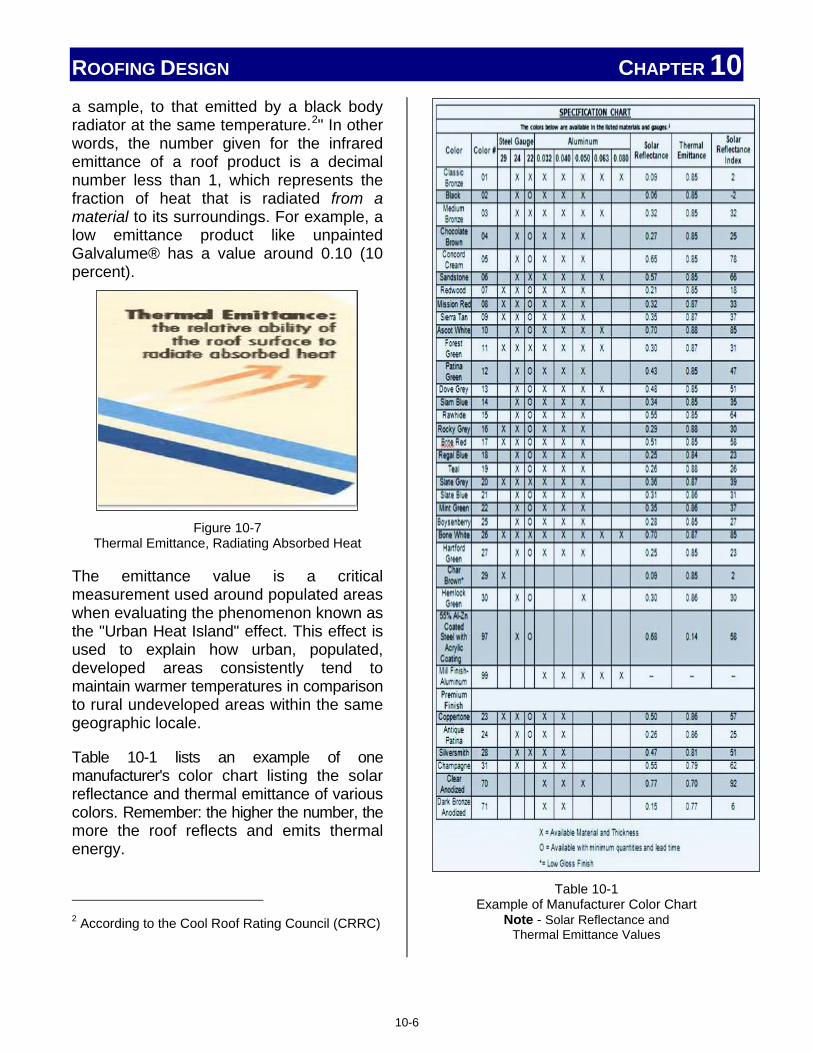
ROOFING DESIGN CHAPTER 10 a sample, to that emitted by a black body radiator at the same temperature.2" In other words, the number given for the infrared emittance of a roof product is a decimal number less than 1, which represents the fraction of heat that is radiated from a material to its surroundings. For example, a low emittance product like unpainted Galvalume® has a value around 0.10 (10 percent).
Figure 10-7
Thermal Emittance, Radiating Absorbed Heat
The emittance value is a critical measurement used around populated areas when evaluating the phenomenon known as the "Urban Heat Island" effect. This effect is used to explain how urban, populated, developed areas consistently tend to maintain warmer temperatures in comparison to rural undeveloped areas within the same geographic locale.
Table 10-1 lists an example of one manufacturer's color chart listing the solar reflectance and thermal emittance of various colors. Remember: the higher the number, the more the roof reflects and emits thermal energy.
2 According to the Cool Roof Rating Council (CRRC)
Table 10-1
Example of Manufacturer Color Chart Note - Solar Reflectance and
Thermal Emittance Values
10-6

ROOFING DESIGN CHAPTER 10 A common misconception in applying these terms is the assumption that the highest solar reflectance and the best infrared emittance ratings are the right selection for every project. This is simply NOT true. There are different climate zones, and not all will benefit from the high reflectance and emittance of some roofing materials. In fact, the high ratings may be detrimental if installed in certain climate areas. It is important that the specific needs of the building and the location be properly evaluated before specifying the material. This is a job typically done by an architect or design engineer.
10.3.2 Ventilation
Ventilation is the exchange of air, in, around, and throughout the roof system. Proper ventilation of the roof is necessary for meeting the design specifications of the roof, as well as maintaining and sustaining a long life to the roof system. Ventilation is very important to a metal roof system in order to minimize the effects of condensation. Ventilation items are discussed in Section 8.1, Roof Vents- Types and Applications, while condensation details are covered in more detail within Section 10.4 of this chapter. Additional purposes of roof ventilation will vary based on climate conditions.
In cold climates, the primary purpose of ventilation is to maintain a cold roof surface. This helps control the formation of ice dams from melting snow and also vents any moist air which escaped from the conditioned portion of the shelter to the roof and attic areas, to the outside, avoiding condensation on the metal roofing.
In hot climates, the purpose of ventilation is to expel solar heated air from the roof and attic area, reducing the cooling load of the structure.
The amount of ventilation required may be determined by applicable building codes or unique design considerations, such as high humidity, agricultural use, etc. Roof ventilation is typically provided through eave and ridge vents, as well as above sheath ventilation. This air flow is illustrated in Figure 10-8.
Figure 10-8
Typical Air Flow for Roof Ventilation
Eave Ventilation along the eave area of the roof can be considered as intake, or incoming air. As outside air enters through the vent, it travels upward towards the ridge of the roof. Eave ventilation can be supplied in several ways:
• Entire "soffit style" panels with preformed vent openings.
• Pre-formed vent openings in eave trim molding.
• Separate vent covers which require a vent opening to be cut out and a vent cover secured over the opening.
Examples of eave vent styles are illustrated in Figure 10-9, but the exact quantity, style, and location of these vents will be determined by the designer.
10-7

ROOFING DESIGN CHAPTER 10
Figure 10-9
Eave and Soffit Vent Examples
Ridge
Ridge vents are considered exhausts, or outgoing air. Ridge vents have the advantage of momentum. Since heated interior air tends to rise; the ridge vent provides a convenient means for this heated air to escape.
Styles and types of ridge vents are too varied to show an example of each type, but several common ridge and gable vent types are illustrated in Figure 10-10. Common ridge vents include types which run the entire length of the roof, while other ridge vents are smaller, rectangular, or square units which mount near the ridge on either, or both sides, but not directly over the ridge crest. Ridge vents may use forced ventilation, or depend on the natural rise of the heated air through the other vents designed to bring in fresh air.
Above Sheathing Ventilation
Many metal roof profiles and installation methods automatically provide above sheathing ventilation. Ventilation channels naturally occur when a panel profile includes major and minor ribs, and side seaming methods involve some form of overlap joint. Although usually blocked at the eave to prevent birds, insects, and dirt from entering, these ventilation paths as illustrated in Figure 10-11 provide an air flow to the underside of the roof panels. This air flow
reduces the formation of condensation and also provides a means of escape and evaporation for any condensation to evaporate and be removed.
Figure 10-10
Examples of Common Ridge and Gable Vent Styles
Figure 10-11
Ventilation Provided by Panel Profile
©National Roofing Contractors Association
©National Roofing Contractors Association
10-8

ROOFING DESIGN CHAPTER 10 As shown in Figure 10-12, when installed over purlins, additional ventilation areas are formed.
Figure 10-12
Additional Ventilation Areas Provided By Purlins
10.3.3 Insulation Requirements
One of the purposes of a roof is to isolate and protect the interior environment of a structure from temperature changes in the outside environment. This is usually accomplished by some form of insulation. This section will discuss two common types of insulation associated with metal roof systems: rigid and continuous. Discussion will begin with a description and the characteristics of the material, then provide typical installation guidelines.
Vapor retarders are not insulation, but are associated with insulation because they are installed at the same time and in direct contact with the insulation. Vapor retarders are often manufactured already attached to the insulating material itself. This is often the case in roll-type insulation (as noted in Figure 10-18). Vapor retarders are critical to the prevention of condensation. They are most effective when installed on the warm side of the building insulation. Vapor retarders are thin and easily torn. Often, when the vapor retarder is separate and installed independently of the insulation, special fasteners are used which provide
more surface contact for securing the material.
If the installation requires a vapor retarder, keep the following key points in mind:
• Make sure the vapor retarder is installed on the correct side of the insulation, normally the warm side.
• Properly seal all side laps, end laps, and any penetrations to prevent the escape of warmer, moist air. This is usually done by taping.
• Vapor retarders are easily damaged, punctured, or torn. Any damage should be repaired when it occurs.
It should be noted that the amount of insulation required on any installation may vary. Code requirements, climate conditions, and structural use are all factors which are used to determine both the type and the amount of insulation necessary. Always make sure the correct material is on-hand and ready to use before beginning an installation.
Code Requirements
Code requirements are established to provide uniformity on minimum design and installation practices. Following "the code" avoids inconsistencies arising from differing approaches used by architects, builders, and installers. Some code requirements were developed through government legislation at federal, state, and local levels, while other codes and standards were established through the cooperative efforts of nationally recognized organizations like the MCA and others. Certain code requirements will be mandatory on an installation solely due to geographical location, structure use, funding requirements linked to construction details, or simply the customer's desire.
10-9

ROOFING DESIGN CHAPTER 10
Installer Note on Fasteners
Whenever insulation is used as part of a metal roof installation, make sure the proper fasteners and clips are available and used. Most insulation does not provide an adequate surface with enough strength for attaching the roof clips and fasteners. Depending on the installation, the following fastener differences may apply: • Longer fasteners may be necessary to
reach through the insulation and into the substrate.
• Different fasteners may be necessary if installing into additional supporting metal framework instead of substrate.
• Fasteners of a different material may be necessary if installing into treated wood support members.
• Additional components, such as bearing plates, battens, purlins, or channels, may be required.
Remember, code requirements are considered minimum standards; are mandatory; and may involve such things like the use, or non-use, of certain materials, the spacing of fasteners, and clearances. Also consider that, although adherence to a code may not be required in certain installations, many of the details within the code should voluntarily be obeyed in order to follow the best practices used within the industry.
Rigid
Rigid roof insulation can be installed over a continuous (solid) or closely spaced deck substrate. The type of insulation, and vapor retardant requirements, will depend on design and code requirements. The potential for condensation may also require a ventilation space and/or slip sheet.
Structural metal panels installed over a solid substrate commonly use a type of rigid insulation as shown in Figure 10-13. This rigid foam insulation is made from polyiso-cyanurate (Polyiso), extruded polystyrene, expanded polystyrene, or fiberglass insulation. There are several methods of attaching the metal roof panels over top of the rigid insulation.
One method uses purlins, metal hat channels, or wood nailers, as battens fastened to the solid deck. These additional pieces are installed perpendicular to the roof slope (parallel to the eave). The roof panel attaches to the purlins, channels, or nailers. The method illustrated in Figure 10-14 uses z-purlins for panel attachment.
Figure 10-13
Installation of Rigid Polyiso Insulation
10-10

ROOFING DESIGN CHAPTER 10
Figure 10-14
Insulation over Solid Deck with Purlins
The battens are the same thickness as the rigid insulation, or a bit thicker, to provide a ventilation cavity. The batten material used should have longevity similar to that of the metal roof being installed. Batten material should have a life expectancy of at least that of the roof material.
Where an increased R-Value is required, a second layer of insulation may be installed over the first layer. This second layer adds additional battens, installed perpendicularly to the first layer of battens, and a second layer of rigid insulation. This added insulation not only increases the overall thermal insulation of the roof, but reduces any thermal bridging which may have arisen from gaps and spaces in the first layer of insulation.
When installing this second layer of battens, the connection between the intersecting battens and the roof deck requires special attention. This intersection must be designed to withstand the designed wind-uplift load of the roof. Installation of the first layer of battens to the roof deck surface also requires adequate wind-uplift strength, especially where battens are spliced.
Another method (Figure 10-15) uses bearing plates to install roof panels over the rigid insulation. The bearing plate supports the clip, preventing it from cutting into the foam. There are two different methods of attaching the clip and bearing plate to the roof. One method uses fasteners which go through both the clip and the bearing plate, attaching into the deck surface. The other uses fasteners to attach the bearing plate to the deck surface, while separate fasteners attach the clip to the bearing plate.
Figure 10-15
Rigid Foam with Bearing Plate and Solid Deck
©National Roofing Contractors Association
©National Roofing Contractors Association
10-11

ROOFING DESIGN CHAPTER 10 The potential for condensation to occur between the metal roof panel and the rigid insulation should be addressed during the installation. An underlayment should be installed on top of the rigid roof insulation in a manner similar to that used on a solid deck and illustrated in Figure 10-16.
Continuous
Roll insulation is normally installed over open purlins or other spaced structural members. Typically made from glass-fiber, this insulation normally has a facer (as shown in Figure 10-19) on one side made from polypropylene, vinyl, or aluminum. The facer acts as a vapor retarder and, depending on the facer material, also provides an attractive finished appearance to the interior side of the roof surface.
Figure 10-16
Underlayment over Rigid Insulation
There are four general methods of installing roll insulation over open framing. These methods apply for both through fastened as well as concealed fastener type systems.
Method 1 (Figure 10-17) - The insulation is rolled out, over the purlins and other structural members. The roof panel is then installed on top of the insulation. The insulation is compressed, especially where panel clips or fasteners are installed. This method can cause problems in cold climates. When compressed, the insulation value is decreased and may be reduced to the point where condensation can develop and cause dripping.
Figure 10-17 Roll Insulation over Purlins
Method 2 (Figure 10-18) - The insulation is installed between the purlins, from rake to rake, and the side tabs of the vapor retarder, if used, are overlapped and stapled or taped together for continuity. At purlins and other structural members, the vapor retarder tabs should be carried over the members, lapped and stapled or taped together. This method also creates reduced thermal insulation at the support members, and can cause condensation like the situation mentioned in Method 1.
10-12

ROOFING DESIGN CHAPTER 10
Figure 10-18
Roll Insulation Between Purlins
Method 3 (Figure 10-19) – The insulation passes over the purlins, or structural members, (as in Method 1) and additional insulated thermal blocks are placed at the purlin and structural member locations. The thermal blocks are placed between the metal roof panel and the insulation. These thermal blocks increase the insulating value in the compressed area, reducing the potential for condensation. They also serve a second purpose and act as a spacer block to prevent bulging of the roof panel where insulating material overlaps the members.
This is an improved version of Method 1. If additional insulation is required, a second, un-faced layer of insulation may be added. This second layer of insulation is typically installed perpendicularly to the roof slope or first layer of insulation.
Method 4 (Figure 10-20) – The insulation passes between the purlins, or structural members, and additional insulated thermal blocks are placed at the purlin and structural member locations. The thermal blocks are placed between the metal roof panel and the insulation. This is an improved version of Method 2.
Figure 10-19
Roll Insulation over Purlins Using Thermal Blocks
Different clips and fasteners may be necessary to adjust for the insulation and thermal block thicknesses. Through-fastened panels using thermal blocks and compressed insulation will have different fastener support characteristics than fasteners driven directly into the support member. The manufacturer of the roof system should be consulted to ensure the correct fasteners and clips are used.
Figure 10-20 Roll Insulation Between Purlins
Using Thermal Blocks
10-13

ROOFING DESIGN CHAPTER 10 10.4 Condensation Issues
Condensation occurs when warmer, moist air comes in contact with cold surfaces, such as framing members and metal roof panels, or a colder region, such as an attic or crawl space. Warm air has the ability to hold more moisture than cold air. When this warm air comes in contact with cooler surfaces or areas, it loses much of this ability and drops of moisture (condensation) are formed. If this moisture collects on insulation, much of its insulating property is lost. Figure 10-21 illustrates this concept.
When installing any metal roof, the formation and removal of condensation needs to be addressed. Installation activities should focus on two condensation goals: to reduce and to prevent. Reduce the initial development of condensation and prevent any damage when condensation does occur.
Reduce the initial development of condensation
The major factor in eliminating and reducing the formation of condensation in the roof system is through proper ventilation. Ventilation is discussed in Sections 8.1 and 10.3.2. Refer to these sections for venting details. A related ventilation issue is controlling any warm moist air escaping into the colder areas or surfaces. Care should be taken to make sure that the correct type and amount of sealant is used, the proper type and amount of insulation installed, and that all joints are properly finished.
Vapor retarders are also critical in preventing the formation of condensation. They eliminate one of the key ingredients for condensation, warm moist air, from coming in contact with the cooler surface areas. Installers should note that vapor retarders are not used in all areas, and in some locations, may be detrimental in preventing condensation.
Vapor retarders and their installation details were discussed in Section 10.3.3 along with insulation.
Figure 10-21
The Formation of Condensation
Prevent damage from condensation
The major factor in achieving the second goal, preventing damage from any condensation which forms, comes from proper installation of appropriate roofing materials, specifically underlayments and slip sheets. This is especially important in leakage-prone areas like valleys, hips, and areas where penetrations to the roof are located, including roof jacks, flashings, and curbs.
10.5 Ice Dams
Icing conditions are never desired on a roof. Ice, icicles, and ice dams, as seen in Figure 10-22, present a danger to those below, and may potentially damage the roof. Ice dams also create pools of melted water.
10-14

ROOFING DESIGN CHAPTER 10
Figure 10-22
Undesirable Ice, Icicles, and Ice Dams
This ponding often covers upslope portions of the roof, including joints, seams, and fasteners, which were not designed to withstand this condition. Ice can still form even when the roof temperature is above freezing. This is illustrated in Figure 10-23. Preparation for such events must take place during the installation of the roof.
Figure 10-23
Ice Dam Formation on a Roof
In locations where the average temperature for January is 30º F or less (Figure 10-24), an ice-dam protection membrane should be installed. A typical ice-dam protection membrane uses a self-adhering polymer-modified bitumen membrane, in addition to standard underlayment and slip sheets.
Figure 10-24 Example of North America Temperature Chart
January Temperatures 30° F or Less
The ice-dam protection membrane should be applied starting at a roof's eaves and extending upslope a minimum of 24 inches from the exterior wall line of a building. For slopes less than 4:12 (18 degrees), a minimum of 36 inches is recommended. A typical ice dam membrane installation over an eave is illustrated in Figure 10-25. Local code requirements, or locations where severe ice damming may occur, may require additional ice-dam protection. Examples of double layer applications are shown in Figure 10-26. Note the additional use of asphalt roofing cement or cold adhesive in the ice dam area.
©Rob Haddock, all rights reserved
©National Roofing Contractors Association
10-15
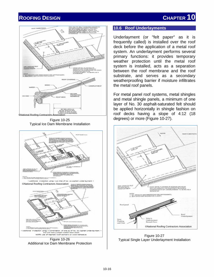
ROOFING DESIGN CHAPTER 10
Figure 10-25
Typical Ice Dam Membrane Installation
Figure 10-26
Additional Ice Dam Membrane Protection
10.6 Roof Underlayments
Underlayment (or "felt paper" as it is frequently called) is installed over the roof deck before the application of a metal roof system. An underlayment performs several primary functions: it provides temporary weather protection until the metal roof system is installed, acts as a separation between the roof membrane and the roof substrate, and serves as a secondary weatherproofing barrier if moisture infiltrates the metal roof panels.
For metal panel roof systems, metal shingles and metal shingle panels, a minimum of one layer of No. 30 asphalt-saturated felt should be applied horizontally in shingle fashion on roof decks having a slope of 4:12 (18 degrees) or more (Figure 10-27).
Figure 10-27 Typical Single Layer Underlayment Installation
©National Roofing Contractors Association
©National Roofing Contractors Association
©National Roofing Contractors Association
10-16

ROOFING DESIGN CHAPTER 10 For roof decks having slopes of 3:12 (14 degrees) up to 4:12 (18 degrees), a minimum of two layers of No. 30 asphalt-saturated underlayment should be applied horizontally in shingle fashion. Installers should note that alternative underlayment materials meeting ASTM requirements are a growing trend within the industry. A typical double-layer underlayment installation is illustrated in Figure 10-28.
Figure 10-28
Double-Layer Underlayment Installation
Underlayments typically are not used with structural metal panel roof systems when intermittent supports are used to carry the roof systems. However, a continuous or closely spaced roof deck may use an underlayment.
Since underlayments serve as a temporary roof surface, fastening should be adequate to retain felts in place until panels are installed. Roofing nails are preferred over staples for attachment of underlayment. Because common organic felt will not
completely seal nail holes, it is recommended that nailing patterns be performed using a minimal number of exposed fasteners, while still achieving the temporary function of holding felts in place until metal panels are installed.
For the same reason, one-inch synthetic cap nails, which increase the temporary wind resistance of felt, are preferred over increased nailing frequency. Commonly used underlayment fasteners are shown in Figure 10-29.
Figure 10-29
Underlayment Fasteners
A slip sheet may be installed over asphalt saturated underlayments for metal panel roof systems. Its purpose is to protect the underlayment from damage, and allow thermal movement of the panels. The slip sheet can be seen in Figure 10-30.
As the roof surface heats up, metal panels tend to stick to the softened asphalt underlayment. This results in the possible ripping and tearing of the underlayment material as the panels expand and contract due to temperature variation.
©National Roofing Contractors Association
10-17

ROOFING DESIGN CHAPTER 10
Figure 10-30
Slip Sheets Prevent Metal Roof Panels from Sticking to Underlayment,
Preventing Rips and Tears
10.7 Thermal Movement
No matter how well designed, engineered, or attractive a metal roof appears, if it is not installed properly with respect to thermal movement, poor performance and damage will quickly occur. The important scientific facts are well known:
• When heated, materials expand.
• When cooled, materials shrink.
• Different materials expand and contract at different rates, and by different amounts.
Taking these scientific facts and applying them to metal roof installation results in several key points an installer needs to remember when installing a metal roof:
• The longer the panel, the more it will expand and contract.
• Different roof materials used on the same system will expand and contract differently.
• Every metal roof experiences large temperature swings. Typically, northern climates experience greater temperature swings than southern climates, often over 100° F.
• Panels should only be "pinned" in one location to allow for thermal movement.
In order to properly install a metal roof which allows for full and proper thermal movement, three factors need to be considered during the installation. The expected amount of thermal movement, the point of fixity, and trim installation are factors in determining the steps an installer must perform during the installation.
10.7.1 Calculating Amount of Thermal Movement
The amount of thermal movement a panel experiences depends on three factors:
• The material (Ce) (refer to Table 10-2)
• The length of the panel (L)
• The change in temperature (∆T)
Table 10-2
Thermal Expansion of Materials (Ce)
The actual amount of change in panel length (∆L) can be determined using the following formula:
∆L = L x ∆T x Ce
(∆ means change)
10-18

ROOFING DESIGN CHAPTER 10 Figure 10-31 illustrates this formula and other important considerations. The term ∆T ("delta T") means the change (∆ "delta") in temperature (T) the panel will experience. It is found by subtracting the lowest temperature from the highest temperature (Thigh – Tlow).
It is important to note that these temperatures are NOT the ambient, or air temperature, but rather the actual surface temperature of the panel. Actual roof temperature is always hotter than the ambient temperature during the day. The maximum high-end temperature (Thigh) will be affected by the color of the panel and its solar absorption characteristics (lighter colors and high gloss finishes will be cooler than dark colors and low gloss finishes). A dark colored panel with low gloss at right angles to the summer sun can approach temperatures of 200° F!
Figure 10-31
Thermal Movement of Common Roof Materials
The maximum low-end temperature (Tlow) is also affected, especially with metal roof panels. In cold, winter, and night-time scenarios, the low extremes of surface temperature (Tlow) can actually dip 25 to 30° F below ambient air. This is due to the principals of radiant energy. Skyward facing objects radiate heat energy towards the night sky. As this energy transfer occurs, the material loses heat reducing its
temperature. It is this same effect that results in dew or frost forming on the ground, roof, or windshield of a car. It is a combination of these factors that can result in ΔT figures of close to 250° F on a metal roof. Even cold northern climates can experience a ∆T in well over 100° F!
This amount of movement is complicated by the fact that not all areas of the roof experience the same conditions at the same time. Some areas are shaded by trees, chimneys, and other structures, while others may be faded, dirty, or covered with debris.
The installer must remember that the roof will move with changes in temperature, and that any errors during installation may jeopardize the integrity of the system. Such errors may be panels out of alignment with the substructure, roof runs which are not straight, or excessive insulation between the panels and substructure. Thermal movement is addressed during the installation process by the proper use of clips, correctly fixing the panel to the substrate, and allowing for this movement when attaching trim and accessories.
10.7.2 Point of Fixity
One-piece and two-piece clips, like the ones shown in Figure 10-32, are used in most concealed fastener installations and allow for thermal movement of the panels.
While these clips perform well for thermal movement and uplift forces, each panel needs additional support and a point of solid attachment to the roof structure. This pinning, or "point of fixity," is necessary to withstand the gravity, and "drag loads" every roof experiences. Gravity attempts to "pull the panels off the roof," while drag loads, like snow, ice, and foot traffic on the roof panels, tend to "pull or slide" the panels
© R
ob H
addo
ck, a
ll rig
hts
rese
rved
10-19
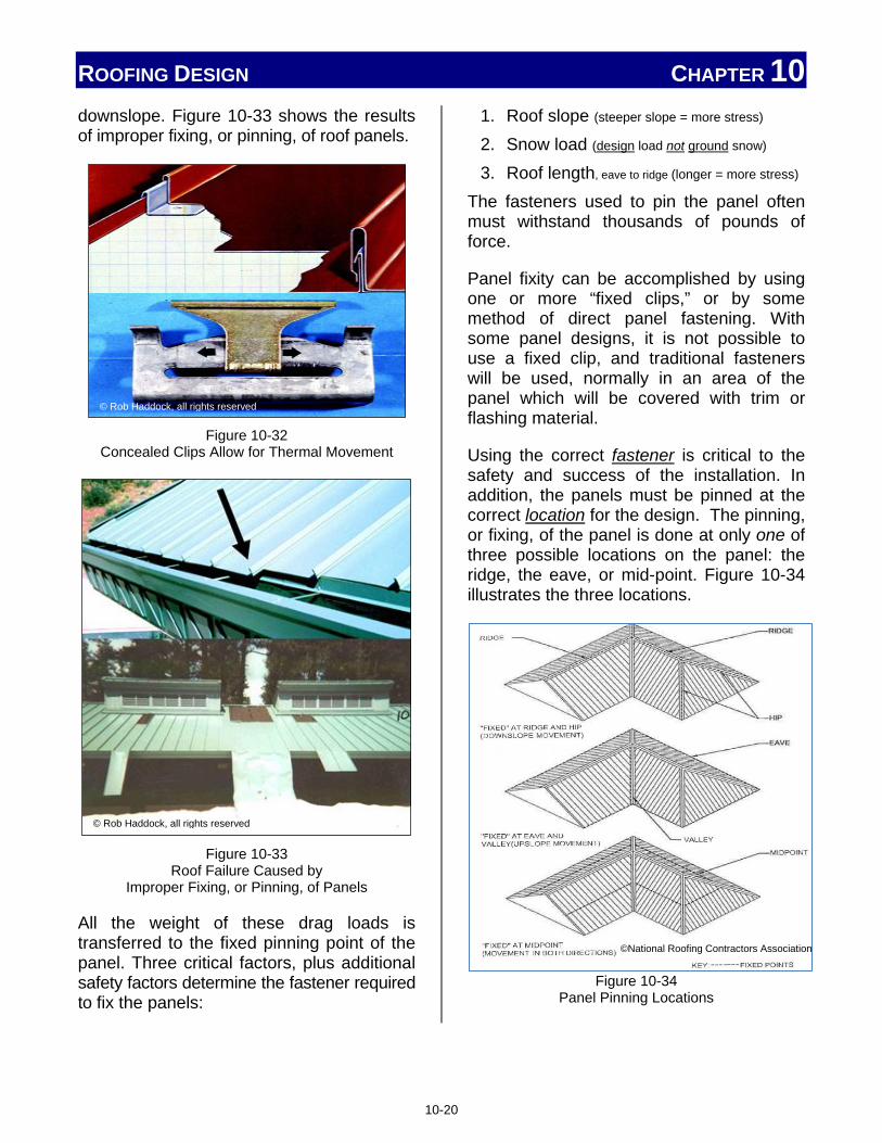
ROOFING DESIGN CHAPTER 10 downslope. Figure 10-33 shows the results of improper fixing, or pinning, of roof panels.
Figure 10-32
Concealed Clips Allow for Thermal Movement
Figure 10-33
Roof Failure Caused by Improper Fixing, or Pinning, of Panels
All the weight of these drag loads is transferred to the fixed pinning point of the panel. Three critical factors, plus additional safety factors determine the fastener required to fix the panels:
1. Roof slope (steeper slope = more stress) 2. Snow load (design load not ground snow) 3. Roof length, eave to ridge (longer = more stress)
The fasteners used to pin the panel often must withstand thousands of pounds of force.
Panel fixity can be accomplished by using one or more “fixed clips,” or by some method of direct panel fastening. With some panel designs, it is not possible to use a fixed clip, and traditional fasteners will be used, normally in an area of the panel which will be covered with trim or flashing material.
Using the correct fastener is critical to the safety and success of the installation. In addition, the panels must be pinned at the correct location for the design. The pinning, or fixing, of the panel is done at only one of three possible locations on the panel: the ridge, the eave, or mid-point. Figure 10-34 illustrates the three locations.
Figure 10-34 Panel Pinning Locations
© Rob Haddock, all rights reserved
© Rob Haddock, all rights reserved
©National Roofing Contractors Association
10-20

ROOFING DESIGN CHAPTER 10 It is important that the installer understand the differences between these three areas and why different installations may require pinning at different panel locations.
For steeply sloped roofs, the location of choice for fixity is at the ridge. At this location, exposed fasteners can be hidden beneath a ridge cover and accumulated thermal movement will be at the eave end. For most steep sloped roofs, water runoff is carried away by a gutter and drainage system.
Conversely, the popular point of fixity for low slope systems is at the eave. The primary reason for this preference is that such systems are often hydrostatic by design, and it is much easier to waterproof a joint that is stationary rather than one that must move. Such a system will then accumulate thermal movement to the ridge where a "bellows" style ridge flashing can accommodate differential movement of the two opposing roof planes while maintaining a hydrostatic seal.
These statements are not meant to be all-inclusive, and there are exceptions in both cases. On occasion, by design, the panel may be fixed at a third location, its midpoint. Figure 10-35 shows how pinning at the mid-point has the advantage of dividing thermal movement in half by sending it in both directions rather than one. Major dis-advantages are that mid-point fasteners are the through-fastened type, which carry the possibility of leakage, and are normally visible after the installation.
10.7.3 Trim Attachment
Having chosen a point of fixity for the metal panel system, it then becomes critical to ensure that such a point is singular. In other words, the panel should not be pinned inadvertently at any other point along its
Figure 10-35
Pinning at Midpoint Cuts Thermal Movement in Half
length. To do so will likely produce a failure of some sort. An installer needs to be mindful of this concept wherever gaps, transitions, or accessories are located within a roof system. On larger structures, roof expansion joints are used to minimize the effects of stresses and movements of a building's components. The effects of these stresses have the potential to cause damage to the roof system by splitting, buckling, or ridging. Expansion joints in a roof assembly must be located in the same location as the building structural expansion joints, although they may be required in other locations. For new construction, it is the designer's responsibility to account for any building movement, the placement of the expansion joint, and the design details. Several expansion joint examples are shown in Figure 10-36. It is the installer's responsibility to ensure that the installation is performed properly.
As previously mentioned and demonstrated in Chapter 8, Common Roof Accessories, on occasion the thermal movement integrity of a roof system is violated because some construction detail or roof accessory mounting did not preserve this characteristic. Figure 10-37 illustrates how accessories can inadvertently pin the panel to the substrate, and a method of avoiding this accidental pinning.
© Rob Haddock, all rights reserved
10-21

ROOFING DESIGN CHAPTER 10
Figure 10-36
Expansion Joint Examples
Installer Note
Design and as-built construction should be scrutinized by the installer for point of fixity. A fascia break detail, for example, fixes the panel at the point of the break. To fix it again at its opposite end would constitute double pinning.
Many times the accidental double-pinning of a panel occurs by other trades, and even by the customer or maintenance personnel. It may also take place after the initial installation of the roof system.
Figure 10-37
Pinning Around Accessories
10.8 Oil Canning (Surface Distortion)
Oil-canning is prevalent in light gauge, cold-formed metal products, especially those with wide, flat, pan areas. Oil canning is not a performance issue but an aesthetic issue.
10.8.1 Definition
Oil-canning refers to physical distortions in the flatness of the metal. This distortion can be clearly shown in Figure 10-38. It should be remembered that this condition does not have any adverse effect on the structural integrity or the weatherproofing capability of the panel.
© R
ob H
addo
ck, a
ll rig
hts
rese
rved
©National Roofing Contractors Association
10-22

ROOFING DESIGN CHAPTER 10 10.8.2 Causes There are a number of potential causes of oil-canning; however, all of them are attributable to residual stresses within the roof panel. These residual stresses may have been added during production of the metal coil, the roll-forming of the panel, or during installation of the roof panel. Panel finishes can draw attention to an oil canning issue.
Figure 10-38
Oil Canning of a Metal Roof
Some paint finishes, clear coats, and metals are highly reflective and bright. These can cause distortions in the panel to be quite obvious and visually distracting. Additionally, the visual effects of oil-canning can be made to look much worse by changing or varying light conditions.
The installer has no control over stresses coming from the manufacture of the metal coil, or the forming of the metal roof panel (assuming the panels were not rolled on-site). However, there are several actions an
installer can perform which will reduce the stresses added to the roof panel and minimize oil-canning during the installation process. Attention to the following issues during installation will reduce the effects of oil canning:
• Alignment of support members • Engagement of panels • Installation of fasteners • Expansion longitudinally • Movement of primary structure • Handling panels
Alignment of support members within the structural system that are produced, fabricated, and installed within "allowable tolerances" can create "non-flat," or contoured, bearing surfaces. The stresses induced while forcing panels to conform to this surface can contribute to oil canning. Installing these panels over uneven solid decking or debris on a solid deck surface, also adds distortion and may cause oil canning.
Most panels accommodate transverse (side to side) thermal expansion by the flexing of ribs, webs, and engagement of the panel side joints. When panels are over-engaged, the added stresses either hinder, or eliminate, these relief features. In extreme cases, the over engagement process itself can generate waviness. Either cause contributes to oil canning.
Installation of the fasteners contributes to oil canning when fasteners are over driven, like the one in Figure 10-39. This operation distorts and creates stresses in the panel which provides a "reading line" along the fastener alignment.
10-23

ROOFING DESIGN CHAPTER 10 Expansion longitudinally is adjusted through proper clip design and installation. Waviness may be amplified when there is uneven fastener restraint along the panel. This sometimes occurs when sealant accidently interferes with designed movement of a clip, or clips become bent or damaged during installation. Such restraint is common on "concealed fastener" systems having fasteners along one edge and an interlock along the other. Waviness caused by thermal forces differs from the other forms of oil canning in that waves can appear and disappear daily as the sun moves across the sky.
Figure 10-39
Over-Driven Fastener
Movement of the primary structure can cause noticeable waviness within panel flats. Depending on the cause of the movement, this distortion can be temporary or sustained.
Handling panels in the flat orientation or twisting panels can induce a wavy appearance to a previously flat panel. Twisting can occur if one corner of a panel is used to lift a panel or to remove the panel from a bundle. Thin panels are easily stressed and deformed by what appear to be slight handling, twisting, and lifting. Proper panel handling is covered in detail is Section 9.3.3, Handling Materials, and Section 11.3, Unloading, Receiving, and Storing Materials. Refer to Figure 10-40 for an illustration of the improper and the proper way to handle and carry long panels.
Figure 10-40
Proper Carrying of Longer Panels
An installer does have control over these installation and handling issues. Instructions to additional labor, erection, and roofing crew members regarding proper handling, spacing, and fastening should be presented based on the manufacturers' material. Since proper panel handling is so important, attention should also be given to informing and training all those involved in production, transportation, and delivery activities.
10.8.3 Mitigation
Many metal roof manufacturers issue disclaimers regarding oil-canning. This means any oil canning which develops is not a warranty issue and not covered; nevertheless, oil canning can become a customer-acceptance issue and one the roofing team must be aware may happen on some installations.
Unless specific tolerances have been incorporated into the contract documents, accepted by both the panel provider and the panel manufacturer, and if reasonable precautions have been taken, oil canning is not grounds for panel rejection. Corrective measures may include the addition of shims under clips, backer rods, or the use of similar types of materials.
©MBMA Metal Roofing Systems Design Manual
10-24

ROOFING DESIGN CHAPTER 10 10.9 Corrosion Issues
To corrode means to destroy or damage by chemical action, and examples of corrosion are shown in Figure 10-41. Any corrosion will shorten the actual working life of the metal roof, not just mar the appearance. While corrosion involves a chemical action, there are also conditions which accelerate corrosion and provide ideal situations for corrosion to develop.
Moisture, dampness, and water, in addition to the interaction between different materials, are key ingredients necessary for corrosion. Whenever possible, the installer should look for, correct (where possible), and avoid creating such conditions. This requires using proper material selection and avoiding certain procedures, while closely following others. It can also be as simple as making sure the work area is clean and that extra materials are removed from the area.
Figure 10-41
Corrosion Damage to a Metal Roof
10.9.1 Ponding Water Corrosion requires water as an ingredient. Ponding on a metal roof provides an ample supply of water to encourage the process. Remember that some roof designs, especially low-sloped roofs, are designed to withstand and handle periods of ponded water in certain areas. The goal, however, is to minimize the amount of liquid, the length of time such events last, and how often they occur. It is also important that these ponded areas are able to drain and dry promptly.
Each roof installation presents its own set of challenges. Figure 10-42 shows completed installations which had several challenges. This picture shows everything done right. A special panel is wide enough to carry all the water off of the roof without creating a water head. The special panels are under the upper roof panels. And an endlap was created at the valley termination point.
Figure 10-42
Proper Planning and Installation Avoids Ponding Issues
10.9.2 Debris
Debris is not part of the roof system. It is, however, a problem which can begin at installation. There are several habits which an installer can establish that will help relieve this debris accumulation.
One way to avoid debris accumulation is to always clean the work area, before, during and after the installation process. Unfortunately, this may also include having to clean up items which are not a direct part of the installer's work. Items left lying around can find their way under panels, containers may spill, and even the slightest item could become a trip or slip hazard, or damage a panel or trim material.
Figure 10-43 shows how quickly common debris, like plywood, pipes, and dirt, can cause corrosion and damage a roof.
10-25

ROOFING DESIGN CHAPTER 10 Another source of accumulated roof debris comes from trees and other foliage in the area. It should be noted that leaves, seed pods, flower remnants, and broken stems and branches have the potential to create areas of corrosion and even damage the roof membrane.
Figure 10-43
Common Debris Can Quickly Damage a Metal Roof
Sharp edges, protrusions, and burrs on fasteners and panels, like those shown in Figure 10-44, not only present a safety hazard, but also tend to snag wind-blown debris. Once snagged, this debris will gather moisture and additional debris. Eventually this "dam" of debris will retain and pond water and corrosion occurs. Good workmanship habits by each individual installer will eliminate this risk. Properly installed fasteners do not have burrs or sharp edges. Cut edges and corners should be properly finished with burrs removed.
10.9.3 Dissimilar Metals
There are certain basics of metal chemistry and corrosion which should be understood by the installer in order to have the foresight to avoid potential corrosive situations. Ignorance of these basics by other trades may result in the violation of some very basic material guidelines and common knowledge within the metal roofing trade. The installer is closest to the work, even when performed by other trades, and can alert the appropriate parties if something that may have a harmful corrosive effect on the metal roof is discovered.
Figure 10-44
Burrs and Sharp Edges Snag Debris
Note that paints which are typically used on coated steel and aluminum panels do little to change or improve the corrosive mechanisms discussed below. The total film thicknesses typically used within the industry are below one mil (.001"), and therefore, moisture permeable. Because of this fact, the same corrosive mechanisms will act upon painted panels as on unpainted panels, even though the corrosion may be somewhat retarded.
The common metals used in construction are zinc, aluminum, carbon steel, nickel stainless steel, copper, and lead. Some of these metals are compatible with each other and others are not.
© Rob Haddock, all rights reserved
© Rob Haddock, all rights reserved
© Rob Haddock, all rights reserved
10-26

ROOFING DESIGN CHAPTER 10
• Generally, stainless steel gets along well with anything.
• Copper gets along with lead or stainless, but nothing else. In fact, copper has a very severe corrosive reaction with steel, aluminum, and zinc.
• Care must be used when using aluminum panels and contact with zinc should be avoided. Aluminum ancillary items such as fasteners, roof curbs, and clamps are reasonably compatible with Galvalume®, galvanized metal and steel.
Refer to Table 10-3 as the relationship between metals in the galvanic series is explained. When dissimilar metals are in contact and water is present, the more noble metal (lower on the list) will induce corrosion of the less noble (higher on the list). Since steel, aluminum and zinc are high on the galvanic scale; they are usually the metals that suffer the corrosion.
Table 10-3
Galvanic Series of Metals
It is of critical importance to the installer, and anyone involved in the metal roofing trade, to note the following important dangers. First, the most noble metal on the list, graphite, is the primary metal called "lead" in the
common pencil. When this is used on any metal panel, trim, or other material, corrosive activity begins when moisture is present. As shown in Figure 10-45, common installer markings rapidly become points of corrosion. Permanent markers should be used instead of pencils.
Figure 10-45
Corrosion Caused by Graphite Pencil
Secondly, other than stainless steel, all other common roofing metals are higher than copper on the galvanic chart. Extreme caution must be used by installers and other tradesmen to avoid exposing the metal roof to copper. This also includes exposure to treated wood and runoff from copper plumbing, HVAC equipment, and other copper-based products. A high concentration of copper-based chemicals is applied to most pressure treated wood within the construction industry. This copper will quickly stain and corrode the roof surface as shown in Figure 10-46.
Figure 10-46
Staining and Corrosion from Copper Runoff
10-27
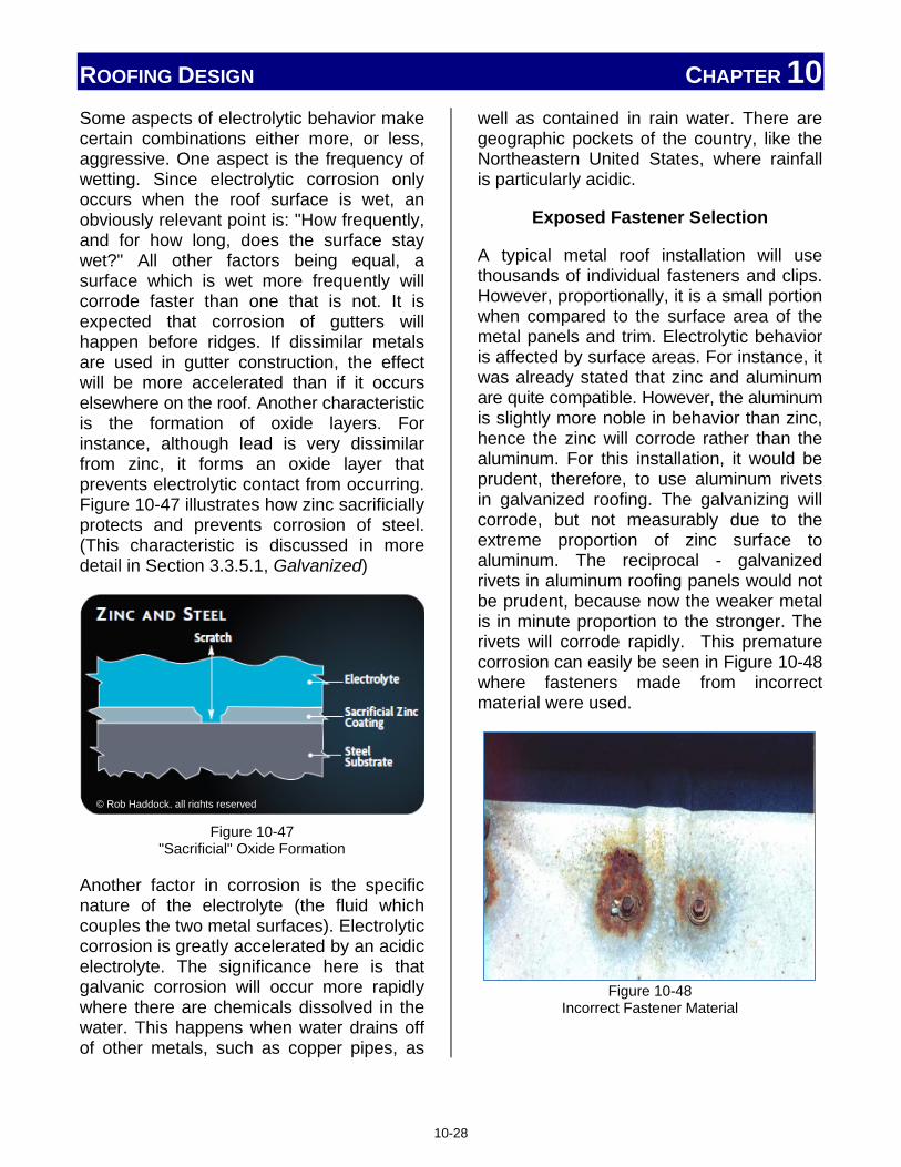
ROOFING DESIGN CHAPTER 10 Some aspects of electrolytic behavior make certain combinations either more, or less, aggressive. One aspect is the frequency of wetting. Since electrolytic corrosion only occurs when the roof surface is wet, an obviously relevant point is: "How frequently, and for how long, does the surface stay wet?" All other factors being equal, a surface which is wet more frequently will corrode faster than one that is not. It is expected that corrosion of gutters will happen before ridges. If dissimilar metals are used in gutter construction, the effect will be more accelerated than if it occurs elsewhere on the roof. Another characteristic is the formation of oxide layers. For instance, although lead is very dissimilar from zinc, it forms an oxide layer that prevents electrolytic contact from occurring. Figure 10-47 illustrates how zinc sacrificially protects and prevents corrosion of steel. (This characteristic is discussed in more detail in Section 3.3.5.1, Galvanized)
Figure 10-47
"Sacrificial" Oxide Formation
Another factor in corrosion is the specific nature of the electrolyte (the fluid which couples the two metal surfaces). Electrolytic corrosion is greatly accelerated by an acidic electrolyte. The significance here is that galvanic corrosion will occur more rapidly where there are chemicals dissolved in the water. This happens when water drains off of other metals, such as copper pipes, as
well as contained in rain water. There are geographic pockets of the country, like the Northeastern United States, where rainfall is particularly acidic.
Exposed Fastener Selection
A typical metal roof installation will use thousands of individual fasteners and clips. However, proportionally, it is a small portion when compared to the surface area of the metal panels and trim. Electrolytic behavior is affected by surface areas. For instance, it was already stated that zinc and aluminum are quite compatible. However, the aluminum is slightly more noble in behavior than zinc, hence the zinc will corrode rather than the aluminum. For this installation, it would be prudent, therefore, to use aluminum rivets in galvanized roofing. The galvanizing will corrode, but not measurably due to the extreme proportion of zinc surface to aluminum. The reciprocal - galvanized rivets in aluminum roofing panels would not be prudent, because now the weaker metal is in minute proportion to the stronger. The rivets will corrode rapidly. This premature corrosion can easily be seen in Figure 10-48 where fasteners made from incorrect material were used.
Figure 10-48
Incorrect Fastener Material
© Rob Haddock, all rights reserved
10-28

ROOFING DESIGN CHAPTER 10 These same principles are true when using stainless steel, which is normally compatible with everything, as a fastener, rivet, or other attachment hardware for panels of other metals. The opposite however, is not true. When attaching stainless panels, stainless fasteners must be used. Galvanized or aluminum fasteners will corrode rapidly when in contact with stainless in this scenario, again due to the proportions of surface areas.
10.9.4 Cement, Mortar and Other Alkalis
Aluminum and metallic coatings used on steel sheet that contain aluminum, (Galvalume®, Zincalume®, Aluminized) have a severe sensitivity to strong alkalis. Sometimes, highly alkaline cleansers are used in the cleaning of certain rooftop HVAC equipment. This should be avoided on such roofs. Cementious materials are also very alkaline, including concrete, brick and block mortar, and stucco. As shown in Figure 10-49, these mortars pose a very severe threat to the above metals when wet. Corrosion caused by these alkalis will be made apparent by a conspicuous black stain on the panel surface. When dry, and freely draining, cement mortars do not seem to be a chemical problem, but they are highly abrasive and can scratch, mar, and damage the metal roof surface.
Construction trades should be sequenced so that adjacent masonry work is complete before roof materials are put in place. If this is not possible, the roof surface must be thoroughly protected, which is almost a practical impossibility. If a spill occurs, it must be immediately removed and thoroughly cleaned and rinsed with clean water to prevent damage.
Figure 10-49
Cement, Mortar, and Related Products Can Damage Metal Roofs
10.10 Integration with Gutter System
The gutter system is designed to control drainage from the roof system. Integration of the metal roof system with the designed gutter system should provide effective water transfer with minimum splash-over of the gutter and minimum back-up of water trying to enter the gutter system. There are two types of gutters: hanging (externally attached) and built-in. The gutter design and installation must ensure adequate drainage and strength, including any ice and snow loading during colder condition. It must do all this and still remain leak free. These considerations require attention to the gutter size, style, attachment, location, and spacing of fasteners and other items.
10.10.1 Drip Edge
The drip edge is defined as a metal flashing or other overhanging component with an outward projecting lower edge, intended to control the direction of dripping water and help protect underlying building components. The drip edge is part of the roof system and is made in several styles. Both low-slope
10-29

ROOFING DESIGN CHAPTER 10 and steep-slope roof systems commonly use "L" and "T" shaped profiles, illustrated in Figure 10-50, when interfacing with a gutter system.
Figure 10-50
L and T style Drip Edge Profiles
In steep-slope roof applications, either "L"-type or "T"-type profiles may be installed at the roof's eave and/or rake. In a typical application, the edge metal is fastened to the deck, if it can be nailed. Succeeding pieces are installed by overlapping the next piece (Figure 10-51), or by using overlapping (Figure 10-52) or concealed (Figure 10-53) joint plates.
Figure 10-51
Overlapping of Drip Edge Material
Figure 10-52
Drip Edge with Overlapping Joint Plate
©National Roofing Contractors Association
©National Roofing Contractors Association
©National Roofing Contractors Association
10-30

ROOFING DESIGN CHAPTER 10
Figure 10-53
Drip Edge with Concealed Joint Plate
It is common that the end joints and corner pieces are not sealed, soldered, or welded. Only the flange of the edge metal is fastened to the deck when used in a steep-slope roof system, the lower edge is normally held in place with a cleat. Cleat details are illustrated in Figure 10-54.
Figure 10-54
Fascia and Cleat Installation Details
If an open, or unnailable, deck is used, the installation may require wooden nailers, cleats, or some other method of securing the edge metal, similar to the method shown in Figure 10-55.
Figure 10-55
Nailer Details for Drip Edge Material
In some installations, a "T" profile is commonly used as the edge metal at the downslope perimeters and rake edges of metal panel roof systems. The extended flange on the face of the "T" profile edge metal also functions as a cleat that secures the ends of the metal panels along the eave. The "T" profile edge metal is typically secured at its lower edge with a cleat, and the roof flange is fastened to the deck. Typical installation details are illustrated in Figure 10-63, while trim joints are illustrated in Figure 10-56.
©National Roofing Contractors Association
©National Roofing Contractors Association
©National Roofing Contractors Association
10-31

ROOFING DESIGN CHAPTER 10
Figure 10-56
"T" Style Drip Edge
10.10.2 Gutter Sizing
Gutter size is determined by the roof slope area and the anticipated amount of rain an area historically receives. While gutter sizes will vary, common profiles are used and illustrated in Figure 10-57 for built-in gutters, and Figure 10-58 for external, hanging gutters. A good gutter design will have a front face lower than the back face to allow excess water to spill over in a heavy downpour, or in situations where the gutter or downspout is clogged. The lengths of the gutters will also vary. Some are pre-formed and ordered from the manufacturer in standard lengths, while others may be roll-formed to length on-site.
Figure 10-57 Typical Built-In Gutter Profiles
Figure 10-58
Typical Hanging Gutter Profiles
Built-in Gutter Systems Interfacing with built-in gutters will vary by the location of the gutter. Built-in gutters located on eaves will be similar to externally hung gutters. A built-in gutter is often discouraged due to complexities of waterproofing requirements. For built-in gutters:
©National Roofing Contractors Association
©National Roofing Contractors Association
©National Roofing Contractors Association
10-32

ROOFING DESIGN CHAPTER 10
• Underlayments should be used and should consist of a minimum of one layer of No. 30 asphalt saturated roofing felt. Self-adhering modified bitumen membranes may also be used with isolation/protection sheets beneath soldered joints. A slip sheet over the underlayment is suggested, to allow for thermal movement of the gutter.
• Weathertight seaming and joining is critical to performance.
• Metal types must be compatible between gutter, flashing, and roofing materials. Incompatible materials will cause both visual and performance problems as seen in Figure 10-59.
Figure 10-59
Incompatible Gutter, Flashing, and Roof Material
• Controlling expansion is important. Provisions for expansion and contraction must be incorporated into the design, and clearances at gutter ends, corners, and supports are necessary. Downspout locations must accommodate gutter movements. Using metals with high rates of thermal expansion, such as aluminum and
zinc, should be avoided. Be mindful of not double-pinning gutter material.
Hanging Gutter Systems
Interfacing with hanging gutters normally takes place at the eaves of the roof. The gutter size and profile will be factors in determining the method used to mount the gutter system. Three common support systems are:
1. Straps. 2. Brackets. 3. Brackets and straps.
Hanging gutter systems may use "L" or "T"-type drip edge material, and may be used with architectural or structural style panels. Installation details are shown in several figures as follows:
"L"-type drip edge installations are shown in:
• Figure 10-60, "L"-Type Downslope
• Figure 10-61, "L"-Type Downslope with Gutter and Brackets
• Figure 10-62, "L"-Type Downslope with Gutter and Brackets and Straps
"T"-type drip edge installations are shown in:
• Figure 10-63, "T"-Type Downslope
• Figure 10-64, "T"-Type Downslope with Gutter
• Figure 10-65, "T"-Type Downslope with Gutter and Brackets
The illustrated examples are for general information purposes only. Always use the manufacturer's recommended materials, and follow the manufacturer's suggested methods and procedures.
10-33
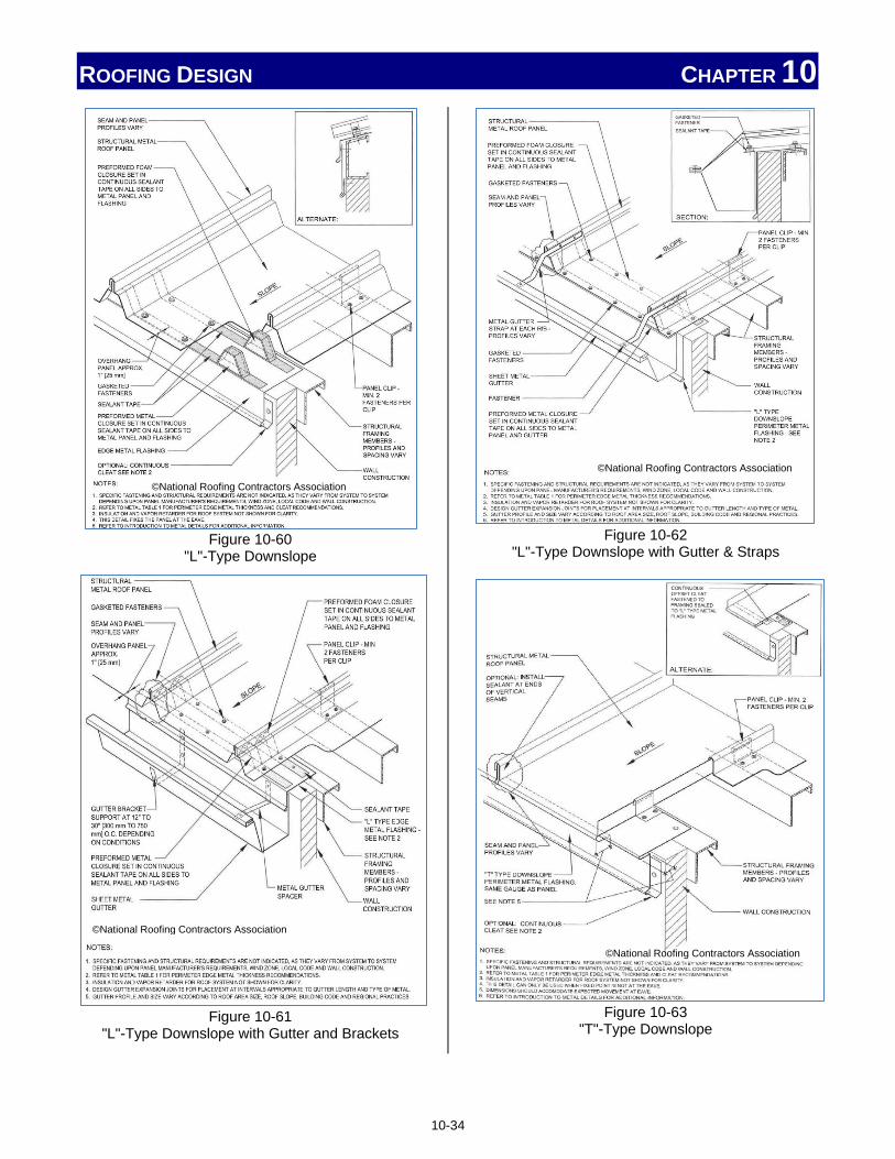
ROOFING DESIGN CHAPTER 10
Figure 10-60 "L"-Type Downslope
Figure 10-61 "L"-Type Downslope with Gutter and Brackets
Figure 10-62
"L"-Type Downslope with Gutter & Straps
Figure 10-63
"T"-Type Downslope
©National Roofing Contractors Association
©National Roofing Contractors Association
©National Roofing Contractors Association
©National Roofing Contractors Association
10-34

ROOFING DESIGN CHAPTER 10
Figure 10-64 "T"-Type Downslope with Gutter
Figure 10-65
"T"-Type Downslope with Gutter and Brackets
10.10.3 Apron
Apron flashing, illustrated in Figure 10-66, is a term used for a flashing that is located at the juncture of the top of a sloped roof and a vertical wall, chimney or steeper-sloped roof.
Any apron flashing should be securely, and appropriately, sealed against the chimney, wall, or barrier. The apron should also be secured along the roof membrane surface but allow for thermal movement.
Figure 10-66 Apron Flashing Around a Chimney
10.11 Water Shedding and Weathertightness Theory
The primary purpose of a roof system is to prevent the infiltration of water and the outside environment. Metal is the ideal material for this purpose. Metal does not leak. Infiltrated water can only enter a metal roof system where there is a puncture or a joint. With this in mind, there are certain areas requiring special attention during a typical installation. Those areas include:
• Back water laps
• Obstructions to quick water egress
• Valley sizing
• Sealant placement
• Proper seating of fasteners
©National Roofing Contractors Association
©National Roofing Contractors Association
©National Roofing Contractors Association
10-35

ROOFING DESIGN CHAPTER 10 10.11.1 Back Water Laps A back water lap is a lap joint which is exposed to water flow in the opposite direction. This opposing direction, coupled with the pressure of the water flow, forces water through against seam, joint or opening.
10.11.2 Obstructions to Quick Water Egress from Roof
A properly designed roof and drainage system will plan for occasional obstructions in the primary drainage path. A secondary draining method should be incorporated into the installation. An obstruction is a physical disruption or a blocking of the discharge. Common obstructions are caused by dirt, debris, and structural damage which block gutters, downspouts, and scuppers, or divert the flow of runoff to those components. Obstructions may also occur when accessories or roof mounted items are installed with inadequate analysis of the impact the additional installation will create as shown in Figure 10-67.
Figure 10-67
Improperly Installed Pipe Blocking Water Flow
10.11.3 Valley Sizing Valley installation details will vary from job to job and roof system to roof system. The differences are due to the size and slope of the roof; the type and size of the panel
being installed, and even the manufacturer. Other geographic, climatic, and engineering factors may affect the requirements of each valley installation. There are still several general guidelines an installer should follow and consider whenever installing a valley.
Even under normal conditions, the valley area of the roof will experience significantly more water exposure than other portions of the roof. The valley, by its nature, tends to collect and accumulate leaves, foliage, and debris which may disrupt flow and cause other problems.
Most manufacturers produce specific valley material for use with the roof panels being installed. This valley material typically has a "W" shaped profile, and is available in several widths for design requirements. A typical installation with panel clips is shown in Figure 10-68.
Figure 10-68
Typical Valley Installation
Consider 36" of 30# underlayment, 18" on each side of center a minimum requirement, plus a slip sheet as necessary. However, most installations will require additional material. All material should extend past the width of the valley flashing and be adequately covered by other underlayment. Often "peel and stick" polymer-modified
©National Roofing Contractors Association
10-36
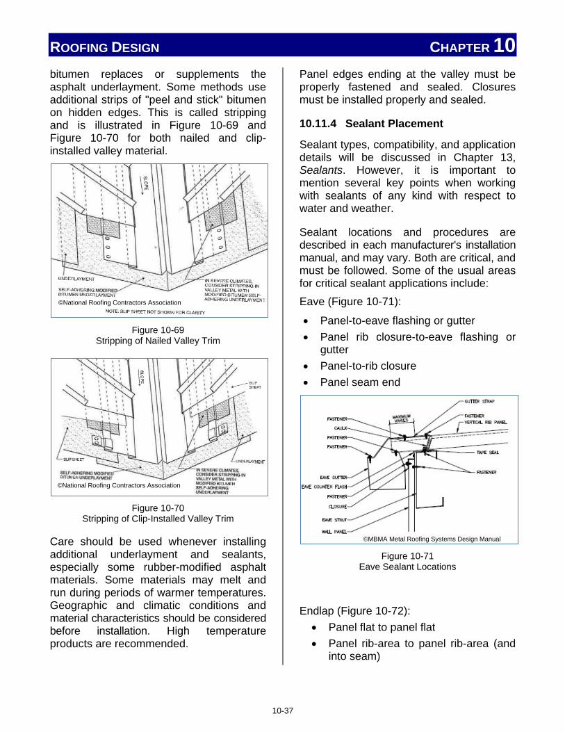
ROOFING DESIGN CHAPTER 10 bitumen replaces or supplements the asphalt underlayment. Some methods use additional strips of "peel and stick" bitumen on hidden edges. This is called stripping and is illustrated in Figure 10-69 and Figure 10-70 for both nailed and clip-installed valley material.
Figure 10-69
Stripping of Nailed Valley Trim
Figure 10-70
Stripping of Clip-Installed Valley Trim
Care should be used whenever installing additional underlayment and sealants, especially some rubber-modified asphalt materials. Some materials may melt and run during periods of warmer temperatures. Geographic and climatic conditions and material characteristics should be considered before installation. High temperature products are recommended.
Panel edges ending at the valley must be properly fastened and sealed. Closures must be installed properly and sealed.
10.11.4 Sealant Placement
Sealant types, compatibility, and application details will be discussed in Chapter 13, Sealants. However, it is important to mention several key points when working with sealants of any kind with respect to water and weather.
Sealant locations and procedures are described in each manufacturer's installation manual, and may vary. Both are critical, and must be followed. Some of the usual areas for critical sealant applications include: Eave (Figure 10-71):
• Panel-to-eave flashing or gutter • Panel rib closure-to-eave flashing or
gutter • Panel-to-rib closure • Panel seam end
Figure 10-71
Eave Sealant Locations
Endlap (Figure 10-72): • Panel flat to panel flat • Panel rib-area to panel rib-area (and
into seam)
©MBMA Metal Roofing Systems Design Manual
©National Roofing Contractors Association
©National Roofing Contractors Association
10-37

ROOFING DESIGN CHAPTER 10
Figure 10-72
Endlap Sealant Locations
Ridge (Figure 10-73) : • Panel to closure components • Closure components to ridge flashings
Figure 10-73
Ridge Sealant Locations
Terminations (Figure 10-74) : • Panel to flashing at rakes or gables • Panel to flashing at longitudinal
expansion joints • Panel to flashing at parapet conditions
Figure 10-74
Termination Sealant Locations
Penetrations (Figure 10-75):
• Panel and ribs to preformed curbs • Panel and ribs to other roof penetrations
Figure 10-75
Penetration Sealant Locations
Flashings (Figure 10-76): • Laps of adjacent flashing segments • Flashings to panels
©MBMA Metal Roofing Systems Design Manual ©MBMA Metal Roofing Systems Design Manual
©MBMA Metal Roofing Systems Design Manual
©National Roofing Contractors Association
10-38

ROOFING DESIGN CHAPTER 10
Figure 10-76
Flashing Sealant Locations
Caution should also be used when applying sealant around concealed clips. These clips are designed and are required to have room to move after installation as the roof panel expands and contracts. If movement is restricted by coincidental contact with misapplied sealant, two possible problems may result. One, the panel may deform, or oil canning may occur. The other, and more frequent occurrence, is that the strength from thermal movement actually "shears" and tears the sealant causing an area of potential leakage. This may be avoided by following the manufacturer's instructions, especially with respect to the location and amount of sealant necessary.
10.11.5 Proper Seating of Fasteners
Once the correct fastener is selected and proper spacing and locations are understood, there are three things that can still go wrong when installing the fasteners. Fasteners can be over-driven, under-driven, or driven at an improper angle to the panel as shown in Figure 10-77.
Figure 10-77 Fastener Conditions after Installation
Under-driven fasteners Under-driven fasteners, like the one shown in Figure 10-78, will definitely leak, but also pose other problems. Under-driven fasteners reduce the roof's resistance to uplift forces, and make the panels and roof structure more susceptible to excessive movement and likely damage. They also reduce the roof's ability to properly act as a system and prematurely fail.
Figure 10-78 Under-Driven Fasteners Will Leak and Corrode
Over-Driven Fasteners
Over-driven fasteners, as mentioned previously, also cause problems. As an installer, remember, tighter is not better when discussing fasteners. Over-driven fasteners cause several conditions which can lead to very different problems.
An over-driven fastener may strip out when only fastening thin panels and other roof members. A stripped-out fastener will not apply enough pressure to the area to keep out water and moisture, nor securely hold the material in place.
Over-driven fasteners deform the area surrounding the installation. Depressions
©National Roofing Contractors Association
10-39

ROOFING DESIGN CHAPTER 10 around the fastener provide areas for water, condensation, and moisture to pool, which usually lead to premature corrosion. This can easily be seen in Figure 10-79.
Figure 10-79
Over-Driven Fasteners
Panel deformation resulting from over-driven fasteners also visually mars the overall appearance of the roof surface, especially when using exposed, through-panel fasteners. This becomes even more noticeable when highly reflective coatings and finishes are used.
Installer Tips
There are several things an installer can do to avoid either fastener condition. Confirm and validate:
• All mechanical fastener tools are set-up properly. An off-roof test panel is recommended using scrap material.
• The correct socket is used.
• All tools are in good working order.
• If using pneumatic tools, o Confirm the correct air pressure is
present at the tool itself. o Significant loss of pressure occurs
when long airlines and worn/leaking couplers are used, or when the hose becomes kinked.
Borrowing any tool is risky. The borrowed tool may have different settings than those required. NEVER ASSUME.
All tool settings and pressures should be per roof manufacturer's recommendations.
10.12 Determining Best Roof Type
The installer normally has no control over the selection of the roof to be installed, but should be aware of some of the considerations used to make the final decision. Some of these considerations are based on climatic and geographic data, while other factors involve the actual structure itself, and some are based solely on customer preference.
10.12.1 Area Climate
The climate of an area helps determine both the normal and the extreme conditions the roof system is likely to experience. Separate data is used to evaluate rain, snow, wind, and temperatures. Climatic data can be useful for evaluation of such parameters like hours of sunlight, number of days above or below certain temperatures, etc. Such data affects surface temperatures, expected thermal movements, and likelihood of extreme climatic events.
Climatic data also plays a role in determining fastener spacing, quantity per panel, and details involving drainage and trim installation.
Wind Speeds
The effect of wind was discussed in Section 10.2 when discussing uplift. Wind speed can be a factor in determining the type and slope of a roof, as well as fastener details and methods.
Code Compliant per Region
"Code compliant per region" means the required standards are met based on posted requirements for established geographic regions. While effective in establishing
10-40
ROOFING DESIGN CHAPTER 10 baseline parameters, regional codes fail to consider local factors which may affect a roof installation, such as nearby trees, structures, proximity to significant bodies of water, etc. Regional codes also fail to consider features unique to the structure, the environment inside the structure, or the processes being conducted within or about the structure which may affect roof system requirements. Code compliant per region specifications also fail to consider any local code requirements within that region.
These local and structural factors generally will require additional materials, fasteners, or work, not less than the regional code requirements. Always remember that any code requirements are minimum requirements for the installation. The specific code requirements are what any inspector or auditor will be evaluating when investigating an installation.
Follow Manufacturer's Instructions or Project Specifications
No one understands the product being installed better than the manufacturer. Manufacturers spend thousands of dollars analyzing, testing, and getting their products certified. Manufacturers also analyze the test results in order to develop their warranties and installation instructions.
It is critical for the installer to understand that failing to follow the manufacturer's instructions can void the warranty of the roof, and open the roofing contractor up to many legal difficulties, fines, and litigation.
When the manufacturer's instructions are in conflict with any code the installer is trying to follow, the manufacturer should be contacted for further instructions. It is highly recommended that any variation suggested by the manufacturer be documented, and a
record kept on file in case any issues develop as a result of any changes.
ASCE 7
The ASCE, American Society of Civil Engineers, have established minimum design loads for buildings and other structures. This is commonly referred to as ASCE 7. ASCE 7 is updated periodically with the year added at the end, ASCE7-XX. For example, the current version, ASCE 7-10, establishes guidelines, methods, and formulas for determining dead, live, soil, flood, wind, snow, rain, atmospheric ice, and earthquake loads, as well as their combinations, which are suitable for inclusion in building codes and other documents. Be cautioned that many codes and jurisdictions do not automatically adopt the most current version of ASCE 7.
Standard ASCE/SEI 7 is an integral part of building codes in the United States. Many of the load provisions are substantially adopted by reference in the International Building Code and the NFPA 5000 Building Construction and Safety Code.
The reasons certain materials, procedures, and methods must be used are based on the guidelines established by ASCE 7.
Rainfall Intensity
Except for condensation, virtually all the water a roof system experiences is due to rain. Two rain factors are important considerations in roof design: Rain amounts and rain intensity. Rain intensity is the rate the rain falls, usually given in inches-per-hour. Both rain amounts and rain intensity have plenty of historic data available on which to base a decision.
Typically this historic data is based on the amount of rain a geographic region received
10-41

ROOFING DESIGN CHAPTER 10 during various periods of time, such as 5-minute, 2-hour, 1-day periods, etc.
This information is critical in determining design factors like:
• The amount of runoff a roof is likely to encounter.
• The amount of water, typically in gallons per minute, a drainage system must handle.
• Hydrostatic pressure roof seams must withstand.
Also consider that increased rain intensity is often accompanied by periods of stronger wind and sometimes hail.
These considerations affect the sealant requirements, panel and fastener styles, gutter size, and other installation details.
Snow Loads
The snow load of a roof is not the same as the amount of snow that falls from the sky. Snow load considers the weight of the accumulated snow that remains on the roof. This includes drifted snow as well as any snow held on the roof by snow guards and snow fences. Roof areas which are prone to drifting and snow build up are illustrated in Figure 10-80. Other snow load considerations must factor in such characteristics as wet and dry snow types, and increased weight from the melt and refreeze cycle which occurs daily. Roof size, slope, and amount of sun the roof receives may significantly increase the snow load.
Figure 10-80
Roof Areas Subject to Drifting and Snow Build Up
Temperature Differential
The temperature differences a metal roof may experience will vary greatly and affects some aspects of the installation. The temperature differential of a metal roof structure will be much greater than the ambient, or climate, temperature ranges. This is due to several factors.
The style, color, and coating of the metal roof surface help determine heat absorption of the roof. A darker, lower-luster roof surface can reach temperatures of 200° F, much greater than any ambient temperature. A highly reflective, lighter color panel will reflect much of the heat and remain cooler. The structure beneath the roof surface, any applied insulation, as well as any heat generated by work performed inside the structure, all affect the temperature differential the roof will experience.
Metal roof surfaces are also affected by low-end temperature extremes. Thermal emittance of the metal roof (the ability of the roof to radiate the heat it has absorbed) will cause the temperature of the roof surface to drop below the ambient temperature; sometimes by as much as 25° to 30° F.
©MBMA Metal Roofing Systems Design Manual
10-42

ROOFING DESIGN CHAPTER 10 The large temperature differentials of the roof directly affect the thermal expansion and contraction of the roof panels, thereby affecting installation details, such as fastener types, spacing, and panel pinning.
It is worth noting that it is not always best to designate the "coolest" roof with high reflectivity and low heat absorption. Design selections are based on the climate in an area. In colder environments, a "warmer" roof may actually be a more efficient design for the user. Engineers and designers will use established climate data and roof data to determine the appropriate selection.
10.12.2 Roof Slope
There are two main roof slope classifications: low-slope and steep-slope. Roofs with a slope of 3 inches per foot, or less (3-in-12, or 14 degrees or less) are classified as low-slope roofs. Low-slope roofs are considered to be a water-barrier (hydrostatic) type of roof, meaning they are designed to withstand ponding or slow moving water, including the additional pressure from such accumulated water. Installation factors will focus on sealing of joints, connections and fastener locations, as well as additional underlayment, or moisture barrier, materials.
Roofs with a slope greater than 3 inches per foot (3-in-12, or 14 degrees) are classified as steep-slope roofs. Steep sloped roofs are to be water-shedding (hydrokinetic). Installation factors will focus on directing and withstanding high volumes of fast-moving run-off water, interfacing to the drainage system, and sealing areas where various roof surfaces merge, such as valleys, parapet walls, etc. Additional attention is given to sealing the down-slope end of the panels to prevent any water back-up from leaking under the roof surface.
In addition to the slope of the initial roof, there are instances where other slope transitions will occur. Porch and dock overhangs, structure additions, renovations, or re-roofing applications may require areas where there is a change in the slope of the roof. Typical metal roof transitions are shown in Figure 10-81 and Figure 10-82, although details will vary based on the panel design and many other factors.
Figure 10-81
Transition from Metal Roof to Membrane Roof
A common variation of the transition in Figure 10-81 is the use of a buffer/isolation plate installed which allows runoff from the metal roof portion to run directly onto the membrane surface.
Figure 10-82 Transition from Metal to Metal Roof Slope
©National Roofing Contractors Association
©National Roofing Contractors Association
10-43

ROOFING DESIGN CHAPTER 10 These transitions can occur on low or steep slope roofs and may require special installation methods and additional material, including custom-formed transition trim. Additional details will be discussed in Section 10.12.5, Roof Geometry.
The 2012 IBC (International Building Code) designates several minimum slope requirements for metal roof installations:
• The minimum slope for lapped, non-soldered seam metal roofs without applied lap sealant shall be three units vertical in 12 units horizontal (25-percent slope).
• The minimum slope for lapped, non-soldered seam metal roofs with applied lap sealant shall be one-half unit vertical in 12 units horizontal (4-percent slope). Lap sealants shall be applied in accordance with the approved manufacturer's installation instructions.
• The minimum slope for standing seam of roof systems shall be one-quarter unit vertical in 12 units horizontal (2-percent slope).
• Metal roof shingles shall not be installed on roof slopes below three units vertical in 12 units horizontal (25-percent slope}.
10.12.3 Longest Roof Run
Except for the most basic of roofs, the roof itself is made up of geometric areas of various sizes and shapes. Consideration needs to be given to the area of the longest roof run. This area will have the greatest thermal movement, the longest length of material, and most likely involve end lapping of roof panels. Depending on the style and
configuration of the panel, aesthetic considerations may also apply, such as oil canning and exposed fasteners.
10.12.4 Deck Substructures
Deck substrates were covered in detail in Chapter 6, Roof Deck Substructures. Several considerations are made when a designer selects a roof deck. Structural panels are normally, but not always, attached to spaced structural members over open areas. The panels are specifically designed to support additional weight and loads between the structural members.
Architectural panels, on the other hand, require a solid or closely spaced deck substrate. The deck may be made from plywood, individual wood members, metal decking, or even cement or a similar material. However; the substrate should be smooth and flat, free of debris and obstructions which would cause panel distortion. Underlayment and slip sheets are often required when installing a metal roof over a solid deck substrate. Insulation and vapor retarders are also sometimes specified.
The type of deck, substrate material, and any additional insulation will affect fastener requirements of any roof surface. Always consult with the roof manufacturer for fastener requirements to any specific installation.
10.12.5 Roof Geometry (Hips, Valleys, Dormers, etc.)
Roof profile and geometry are factors used in determining many other aspects of the specified roof. Common roof profiles are shown in Figure 10-83.
10-44

ROOFING DESIGN CHAPTER 10 Historically, each geometric profile originated to meet a need. That need may have been to create a more open storage area, or a sleek, attractive low-profile which is barely visible from the ground. Whatever roof geometry is being installed, attention to the areas of slope change (dormers, hips, valleys, etc.) and roof edges (eave, ridge, and gable ends) during installation is necessary. Roof geometry will also determine a roof's hydrostatic or hydrokinetic characteristics and underlayment requirements.
Figure 10-83
Basic Styles of Roof Design
10.13 Field Measurement
Field measurement of certain roof parameters is the best way to determine the specific requirements for the installation. "Seeing is believing" and taking a field measurement provide critical installation information not available from any drawing. Accurate dimensions cannot be determined from pictures, but should be measured on-site.
10.13.1 Before Ordering
If at all possible, there are several construction details the roofing team needs to confirm before ordering the roofing material. Roof squareness, penetrations, roof mounted equipment, and surrounding features may all affect how the roof panels are laid out, installed, and finished or trimmed. Often, significant savings can be found by slightly shifting panel layouts. Care should be taken to maintain balanced seams on gable ends as well as noting how panel seams fall in relationship to any roof jacks, accessories, and curbs.
Roof condition (in a reroofing situation), accessories, and renovations installed by other tradesmen should be field-evaluated. Rarely can such items be accurately evaluated from drawings and sketches. Field evaluations often reveal opportunities to simplify the installation and reduce costs. For example, rerouting of vents, elimination or removal of unused vents or roof mounted equipment, and similar items can simplify the installation as well as lower the cost.
10.13.2 For Curves
Any radius application, installing metal over a curved surface, is best accomplished after field measurement of the curved section. Figure 10-84 is an example of field measurements a manufacturer typically requires in order to ensure proper material and installation methods are used. Sometimes curved sections are "custom-fit" in order to account for irregularities, or to provide smooth transitions between two sections, meaning the only way to get an accurate dimension is to measure the actual area. Manufacturers often require additional structural information besides dimensions of the curved roof section.
Radius applications require additional work and care in installation. Curving the metal without creasing or damaging the panel,
10-45

ROOFING DESIGN CHAPTER 10 while preventing gaps and leaks at joints is critical. Aesthetic considerations are also a major concern. Most curved applications are in a highly visible section of the roof; therefore, care must be taken to allow the panel to curve without warping, twisting, or distorting. Consideration must also be given to pinning and the potential thermal movement of the curved section of material.
Figure 10-84 Typical measurements for Radius Applications
10.13.3 Eave Overhang
The eave overhang measurement will be a factor on underlayment and ice dam material requirements. In addition to the size and style of trim material that may be required; eave overhang may be a factor in a designer's use of ventilation options. Keep in mind that the overhang portion of the roof is considered a cold portion of the roof, and is especially vulnerable to freezing in colder temperatures.
10.13.4 Pitch
Roof pitch, or slope, has already been discussed in Section 10.12.2, but field measurement of this roof parameter will ensure an accurate estimation of necessary material and supplies.
This can be determined using several methods. One method requires taking a few simple measurements and either calculating, or using a table, to determine the slope or pitch.
Another method uses a simple slope measurement tool as shown in Figure 10-85. This is basically a protractor-type tool, which is placed on the roof slope and directly read off the dial.
Figure 10-85
Slope Measurement Tool
Summary While it is true that designers and engineers normally do not do the roof installation, and installers do not do the design and engineering function, it is important that every installer understands key design concepts and principles involved in roof selection.
Every day, installers are faced with challenges and situations which have no "step by step" solution. Understanding the reasons behind key design areas will allow the installer to either make the best informed decision during an installation, or intelligently discuss the issue with a member of the design or engineering team.
Notes: ____________________________________________________________________________________________________________________________________________
10-46

Chapter 11: Delivery, Receipt, Storage and Handling of Materials Chapter Contents
11. Introduction ...................................................................................................... 11-1
11.1 The Job Site ....................................................................................... 11-1
11.2 Arranging and Scheduling Delivery .......................................... 11-2
11.2.1 Ensure Adequate Space ........................................................ 11-2
11.2.2 Ensure Proper Equipment and Adequate Personnel .......... 11-3
11.3 Unloading, Receiving and Storing Materials ......................... 11-3
11.3.1 Check Weight of Bundles Versus Equipment Capacity ..... 11-3
11.3.2 Panel Length/Spreader Bar ................................................... 11-4
11.3.3 Type of Slings ....................................................................... 11-5
11.3.4 Preplan For Material Layout ................................................. 11-5
11.3.5 Check Materials Delivered Against BOM ............................. 11-7
11.3.6 Check For Damaged Materials ............................................. 11-7
11.3.7 Protecting Panels Until Installation ...................................... 11-8
11.3.8 Masking and Strippable Films ............................................. 11-11
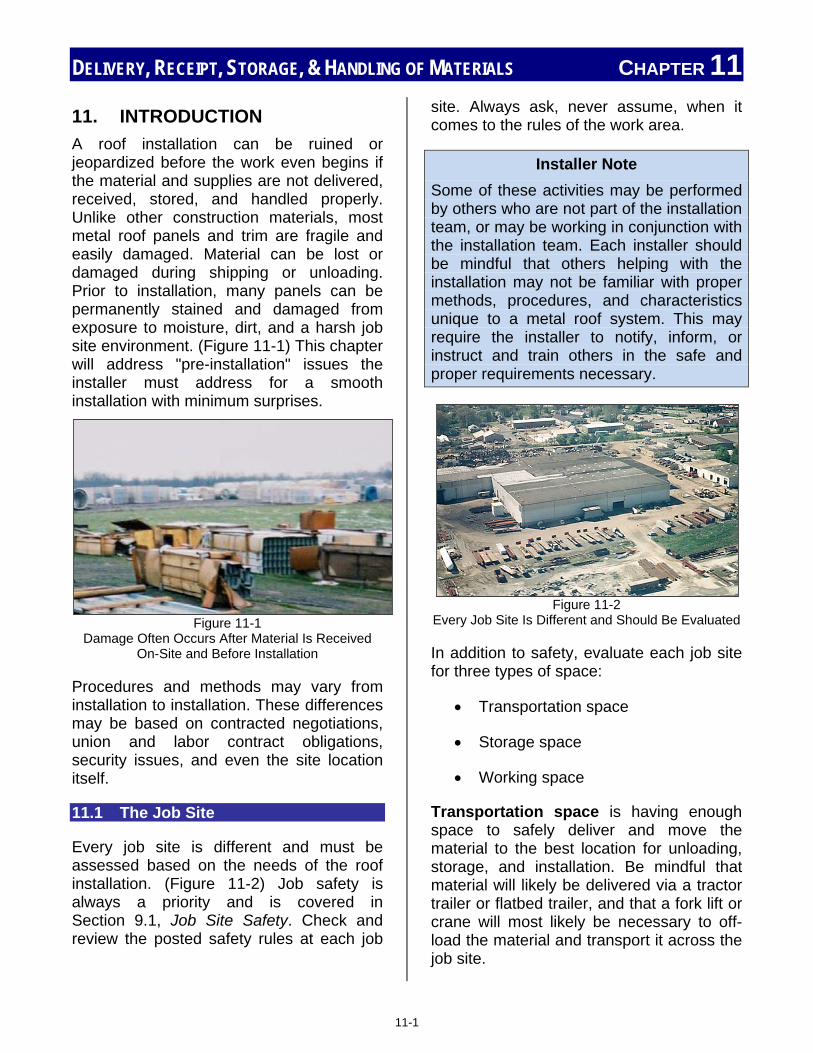
DELIVERY, RECEIPT, STORAGE, & HANDLING OF MATERIALS CHAPTER 11
11. INTRODUCTION A roof installation can be ruined or jeopardized before the work even begins if the material and supplies are not delivered, received, stored, and handled properly. Unlike other construction materials, most metal roof panels and trim are fragile and easily damaged. Material can be lost or damaged during shipping or unloading. Prior to installation, many panels can be permanently stained and damaged from exposure to moisture, dirt, and a harsh job site environment. (Figure 11-1) This chapter will address "pre-installation" issues the installer must address for a smooth installation with minimum surprises.
Figure 11-1
Damage Often Occurs After Material Is Received On-Site and Before Installation
Procedures and methods may vary from installation to installation. These differences may be based on contracted negotiations, union and labor contract obligations, security issues, and even the site location itself.
11.1 The Job Site
Every job site is different and must be assessed based on the needs of the roof installation. (Figure 11-2) Job safety is always a priority and is covered in Section 9.1, Job Site Safety. Check and review the posted safety rules at each job
site. Always ask, never assume, when it comes to the rules of the work area.
Installer Note Some of these activities may be performed by others who are not part of the installation team, or may be working in conjunction with the installation team. Each installer should be mindful that others helping with the installation may not be familiar with proper methods, procedures, and characteristics unique to a metal roof system. This may require the installer to notify, inform, or instruct and train others in the safe and proper requirements necessary.
Figure 11-2 Every Job Site Is Different and Should Be Evaluated
In addition to safety, evaluate each job site for three types of space:
• Transportation space
• Storage space
• Working space
Transportation space is having enough space to safely deliver and move the material to the best location for unloading, storage, and installation. Be mindful that material will likely be delivered via a tractor trailer or flatbed trailer, and that a fork lift or crane will most likely be necessary to off-load the material and transport it across the job site.
11-1

DELIVERY, RECEIPT, STORAGE, & HANDLING OF MATERIALS CHAPTER 11 Consider the ground surface and travel route. Uneven, muddy, or dangerous surfaces should be avoided. Watch for and avoid narrow paths, sharp turns, and areas with no turn around area.
Storage space will involve several areas during the installation. (Proper storage methods and protection are discussed in Section 11.3.7.) Roof material may need to be stored when initially off-loaded, when prepped and staged for initial installation, and when moved to its final location on the roof, where it will be installed. Adding to the concern is that these storage locations may be indoors, outdoors, ground level, above ground, or even roof top. They may be in a secured or an unsecured area. Again, keep in mind that movement of material to these locations will likely involve a crane, fork lift, or some mechanical device with its own set of space requirements.
Working space will most directly affect the installers and their activities. This area must include the necessary space for any installation equipment, and equipment needed to move, form, bend, trim, and cut material; including space for moving and handling long panels. Do not overlook the space required for unpacking, separating, and sorting the material. Instructions and smaller parts are often shipped within other packages. Some material, such as sealers, adhesives, and touch-up materials, may need to be unpacked immediately, and may require special storage conditions.
Give consideration to other work being performed in the area and avoid any interference. Evaluate the flow and path of the work. Paths should be clear, well-marked, and free from obstructions and hazards. Avoid high traffic areas whenever possible. Above ground or roof top work areas should avoid any work near edges or openings. Where applicable, follow all
OSHA and safety rules in marking roof edges, openings, and other hazards.
11.2 Arranging and Scheduling Delivery
Responsibility for the transportation and delivery of the roof system, and its related materials, equipment, and supplies will vary from job to job, and is based on negotiated terms which were established prior to starting the work. Depending on the agreed upon terms, the party responsible may be the roof manufacturer, roof contractor, or a general contractor. Any of these parties may also sub-contract this portion of the work to other parties, adding to the confusion. Ask and make sure all parties understand and are in agreement on the pre-installation details of the roof system.
It's been said that "timing is everything," and there is truth to this statement when applied to the delivery of metal roof material. The issues associated with late deliveries are well-known, but early deliveries cause problems which are just as significant. When material arrives early, there may or may not be equipment and manpower available for off-loading. Then the material must be stored even longer than originally planned, until needed for installation. There may or may not be available storage space, plus there is the added risk of damage while being stored.
Time from on-site delivery of the material to installation should be kept to a minimum, and will require exceptional planning, communication, and cooperation between all parties involved.
11.2.1 Ensure Adequate Space The space required when the roof system is delivered will depend on several factors. The quantity and size of the manufactured materials and how the manufacturer packs and ships the material will determine
11-2

DELIVERY, RECEIPT, STORAGE, & HANDLING OF MATERIALS CHAPTER 11 specifics of the equipment needed and the area required for the material.
Figure 11-3
Ensure Adequate Space for Equipment and Material
Job site characteristics, combined with the space requirements necessary to unload the material, will determine the specific location where the material can be safely unloaded (Figure 11-3). Some jobsites have pre-determined delivery locations, and may provide separate means of unloading and delivering the material within the work area.
11.2.2 Ensure Proper Equipment and Adequate Personnel
The equipment and personnel necessary at the time of delivery will largely depend on the size of material and how it was packaged for shipping. This includes the weight of the material and individual packages.
The vehicle or trailer used to deliver the material will also be a factor. Some styles of trailers will not be able to be unloaded using certain equipment. Certain configurations may require a dock or elevated area in order to unload the roof material, while flatbed trailers and job site conditions may require a forklift designed for outdoor use.
Equipment specifics are covered more thoroughly in Section 11.3, Unloading, Receiving, and Storing Materials.
Another item that is often overlooked involves security. The critical component to security
is the key to the lock. Make sure that the key for any secured gates, areas, and locks will be available at the time the material arrives. It is also important that security personnel be notified of the expected delivery and pertinent details.
11.3 Unloading, Receiving, and Storing Materials
Note: Indented paragraphs in this section are reprinted with permission from the MBMA Metal Roofing Systems Design Manual.
As previously mentioned, the responsibility for unloading and receiving the material may vary based on negotiated agreements. "Unloading", however, should not be confused with "receiving," as the two terms have entirely different meanings. "Unloading" is the physical act of furnishing labor, equipment, rigging, and expertise to remove materials from trucks (normally open flatbeds) at the project site, and to place them in the storage or distribution area.
"Receiving" has other implications which are discussed below. If an independent contractor is responsible for unloading and installation, it does not mean that he automatically accepts responsibility for receiving the material. In fact, the opposite is more often the common practice. Contract language should spell out how these responsibilities are divided and coordinated. In lieu thereof, normal practice is that the installation contractor “offloads", but the party who has furnished the material "receives". If the party responsible for receiving does not have a representative present at
11-3

DELIVERY, RECEIPT, STORAGE, & HANDLING OF MATERIALS CHAPTER 11 the time of delivery to check the shipment and sign documents, the installation contractor may do so, but normally only as an agent for the absent party.
11.3.1 Check Weight of Bundles Versus Equipment Capacity
Handling of individual metal roof panels is covered in Section 9.3, Handing Materials. While individual metal roof panels are lightweight, bundles are not. The length, coupled with the weight of the bundles, necessitates the use of equipment to lift, move, and transport the bundles of material as shown in Figure 11-4. Any time equipment is used with bundles of material, make sure the weight of the bundle is known and the load limits of the equipment are known. The bundle weight should be marked on the bundle itself, available on the shipping documentation, or can be found by calling the manufacturer of the roofing material.
Figure 11-4
Moving Bundled Roof Panels Requires Equipment
The equipment load limits should be clearly marked on the equipment itself. If unknown, the equipment load limits could be determined by checking online, or contacting the manufacturer of the equipment. Additional equipment may also require the use of spreader bars and/or straps.
Figure 11-5 Many Shorter Panels May be Moved by a Fork Lift
Large crates and bundles of material may have different handling requirements from one manufacturer to the next. Some panels are more fragile than others when they are bundled. This is a function of the panels' shape, gauge, material, width, and length dimensions. Crating procedures and designs vary amongst manufacturers as well. Some utilize very elaborate crates which are designed in truss-like fashion to help support panels. Others simply block and band, and still others may offer options. The handling requirements are usually spelled out by each manufacturer in their installation manuals. These requirements should be reviewed by the installation contractor prior to arrival of materials at the site so that he can make arrangements for any special training, hoisting equipment, or rigging that may be needed.
11.3.2 Panel Length / Spreader Bar
While specifics about pick-points can vary greatly, some general statements can be made regarding the handling of bundles of material. Normal over-the-road shipments will involve length restrictions of about 41 feet. Such bundle lengths require some special lifting considerations and separation of
© R
ob H
addo
ck a
ll rig
hts
rese
rved
11-4

DELIVERY, RECEIPT, STORAGE, & HANDLING OF MATERIALS CHAPTER 11 pick-points. Rarely will a conventional forklift, as shown in Figure 11-5, be adequate. When using a spreader beam, as shown in Figure 11-6, two pick-points are often adequate.
Figure 11-6
Spreader Beam with Two Pick-Points
In rare cases, as shown in Figure 11-7, three or more pick-points may be necessary due to panel length, while bundle weights will not usually exceed 3,000 lbs. Always check and confirm the load limit of any lifting device.
Figure 11-7
Longer Panels Require 3 or More Pick-Points
11.3.3 Type of Slings
Two bridled wire rope slings are sometimes used in lieu of a spreader beam, but wire rope should not be
used in direct contact with roof panels or sheet metal trim. Nylon webbed slings are the rigging of choice, and are available in many widths. Sling widths of 4" or more are recommended to minimize damage to the panel edges. When full-length (40') bundles are set on the ground or roof, they should be supported at a minimum of one place for each ten feet of length.
Straps should be clean and free from debris to avoid marring and damaging panels when lifting. Always check the condition of any straps and wire ropes. Any fraying of wire rope, or red threads visible on cloth or nylon straps, spells danger and should not be used. Frayed or damaged straps may break or tear causing damage, injury, or even death. 11.3.4 Preplan for Material Layout
Proper planning of material layout can save significant amounts of time and money during the installation as well as prevent damage to the roof material. In addition to planning the layout of larger panels and pieces, the installer should also plan the location, storage and availability of the smaller material and accessories like clips, fasteners, and sealant.
Material layout should also consider the location of on-site roll-formers, brakes, and trimming tools. Even consideration of the left or right-handedness of the installer will allow the work to flow smoother and can eliminate unnecessary twisting and turning.
Preloading Materials
A common trade practice is to "pre-load" and stage panels and other materials onto the building or roof structure prior to the actual commencement of roofing work. This is shown in Figure 11-8. The
© Rob Haddock, all rights reserved
© Rob Haddock, all rights reserved
11-5

DELIVERY, RECEIPT, STORAGE, & HANDLING OF MATERIALS CHAPTER 11 objective is to place materials in close proximity to where they will be needed, which reduces time and traffic involved in moving materials from place to place. On new construction, this is often done during the installation of the structure. On retrofit and renovation work, it is sometimes done immediately upon delivery of material, or otherwise just prior to the start of the roof installation. In other cases, it may be done at various intervals as the work progresses. That can reduce labor costs, expedite the roof installation, and greatly reduce the possibilities of material damage.
Figure 11-8
Pre-Staging Material on the Roof Has Many Advantages But Caution Must Be Used
Roof panels can also occupy an inordinate amount of physical space on a jobsite when stored on the ground; hence, pre-loading can relieve congestion on the site. When panel material is pre-loaded, it also seems to stay much cleaner by not being exposed to mud splashes and other ground traffic like the panels shown in Figure 11-9.
Figure 11-9
Ground Locations Are Subject To Mud Splashes
There are a number of factors which must be considered before pre-loading any materials. The structure must be in a condition to accommodate the point loads which will occur from pre-loading. This will usually mandate that loads are placed directly over a primary framing component, and not in the middle of a bay, as seen in Figure 11-10. It may also require some special shoring of certain secondary structural components.
Existing construction must be carefully inspected to determine where such bearing points are prior to setting any loads on the roof. Individual bundle weights should be investigated and quantified to be sure they do not exceed what the structure will tolerate. Care should also be taken with regard to nestable hardware, sub-purlins and the like, as the weight of these items can far exceed that of panel bundles. An existing roof should not be pre-loaded with construction materials at a time of year when it is likely to
© Rob Haddock, all rights reserved
11-6

DELIVERY, RECEIPT, STORAGE, & HANDLING OF MATERIALS CHAPTER 11 experience design live loads such as snow or ice.
Figure 11-10
Material Should Be Staged at the Bearing Points of the Roof
When pre-loading, attention should be given to installation particulars, like sheeting direction and bundle quantities, in order to stage materials correctly. Because bundles must be placed over a frame-line, the bundle quantities must also match up with the bay length. For instance, if the bay length is 20 ', then the bundle size for 24" panels should be ten panels - or alternatively twenty panels if they are to cover two bays. When looking at these particulars, it may be necessary to re-bundle material before loading in order to have it staged correctly. Because most products are directional in their installation, and, therefore, have an "upslope" and "downslope" end, care must be taken to place them accordingly.
11.3.5 Check Materials Delivered Against Bill of Material (BOM)
The material received should be checked against the Bill of Material (BOM) prior to beginning any installation. This confirms
that the material received is the same as the material ordered, and matches the ordered quantity.
11.3.6 Check for Damaged Materials
Along with confirmation of the BOM, checking allows for a quick inspection of the material for initial damage. When the truck with the roofing material is received at the site, a transaction occurs whereby the shipper is released from this responsibility. This transaction occurs when the party receiving the material, sometimes the installer, acknowledges (by signature) that the goods are free from damage or loss. For this reason, it is important that a reasonable effort is made to confirm that, in fact, the shipment is complete and free from damage. If shipping damage or loss has occurred, it must be noted on the Delivery Receipt. Normally the Receipt will have a signature line, which says, "Received in good condition except as noted." When this line is signed without notation, it is acknowledgment by the receiving party that all containers and material noted thereon has been received complete and without visible damage.
11-7

DELIVERY, RECEIPT, STORAGE, & HANDLING OF MATERIALS CHAPTER 11
Figure 11-11
Early Detection of Damaged Material Will Help Avoid Delays and Speed Replacement
It is good practice that if damage to a container is visible, it be investigated to be sure that the contents are complete and unharmed, and then noted on the Delivery Receipt: “One container damaged- no loss or damage apparent." Such notation preserves the right to assert a claim later, if upon closer examination, loss or damage is found, as seen in Figure 11-11.
It is common practice that at the time of delivery, the shipment is checked for completeness according to quantities of bags, boxes, and bundles. It is not necessary to count screws, clips, or bolts in a container to ascertain the completeness of each, or to count panels within a crate. The objective is to be sure that the number of crates, bundles, boxes, and so forth are delivered as manifested, and not visibly damaged. Shortages of containers, as manifested, are an issue to be taken up with the freight carrier. A shortage within a container is an issue to be taken up between buyer and seller (shipper). A truck should not be unreasonably detained in order to count parts and pieces, as
long as manifested bundles and containers are properly accounted for on the shipping documentation. If there is an observed shortage, or damage to the shipment, it should be noted on the Delivery Receipt. In addition, the shipper and purchaser should be notified immediately so that arrangements can be made for a freight claim, as well as replacement materials.
Never sign for material which is obviously damaged, or received in a damaged container, without noting such damage on the paperwork at the time of signing. Also notify the appropriate parties of any damage so replacement material can be ordered.
Liability for damaged material will depend on when the damage occurred and circumstances surrounding the manner in which the damage took place.
Installer Note
If an installer proceeds and uses visibly damaged material, the liability of the responsible party is often removed. This means there can be no compensation for damaged material, including labor costs.
Inspection also allows a knowledgeable installer to identify the material and determine if it seems to be correct for the installation.
11.3.7 Protecting Panels Until Installation
Once on-site, it is critical that metal roof materials be protected until installation. This includes any storage, staging, and handling activities. Often material is damaged after it is received, and prior to final installation. Most damage which takes place during this period is cause by:
• Moisture
11-8

DELIVERY, RECEIPT, STORAGE, & HANDLING OF MATERIALS CHAPTER 11
• Handling • Dirt • Physical damage
Standing water and condensation are the primary causes of Moisture damage to roof panels and trim. (See Figure 11-12) Both causes may be eliminated by proper storage methods which allow for drainage of any standing water and "room to breathe" (air flow through the material) especially between individual panels.
Figure 11-12
Pre-Installation Moisture Damage of Roof Panels
The ideal storage method is illustrated in Figure 11-13. When storage using this ideal method is not entirely possible, the following key points must be addressed in order to prevent damage to the material:
• Cover with a water-resistant not a water-proof material. Do not use plastic. Plastic does not allow the area to breathe and produces condensation.
• However, if plastic tarps or sheets are the only material available, they should be blocked off the bundle to allow adequate ventilation.
• Top wrap of the cover overlaps bottom wrap to avoid entrance and ponding of water runoff.
• Stacked material should be sloped for drainage.
• Stacked material should be blocked so the stack is approximately one foot above the ground surface. This allows good air flow as well as avoids ground moisture and surface drainage that may occur. Spacing of the blocks should be close enough to prevent the panel from sagging or distorting. Long panels should be blocked at least every 10 feet.
• Secure the cover to allow air to circulate under the surface.
• Consider inserting spacer blocks between the individual panels. Blocks will allow for air flow and drainage to keep the panels dry, avoiding staining.
If panels or bundles do become wet, it is important to un-bundle and allow them to air-dry to prevent corrosion. Corrosion and staining tendencies will vary based on the material, profile, and bundling method used for the panel. Most manufacturers address this issue in the instructions shipped with the material.
© Rob Haddock, all rights reserved
© Rob Haddock, all rights reserved
11-9
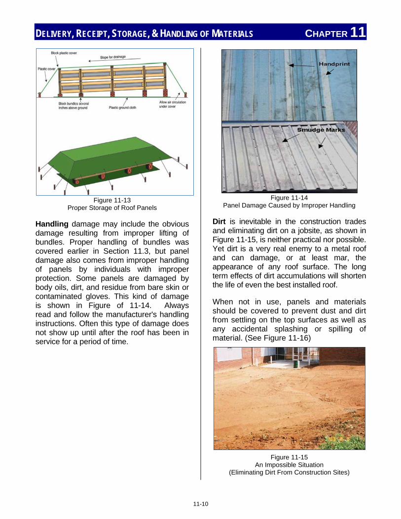
DELIVERY, RECEIPT, STORAGE, & HANDLING OF MATERIALS CHAPTER 11
Figure 11-13
Proper Storage of Roof Panels
Handling damage may include the obvious damage resulting from improper lifting of bundles. Proper handling of bundles was covered earlier in Section 11.3, but panel damage also comes from improper handling of panels by individuals with improper protection. Some panels are damaged by body oils, dirt, and residue from bare skin or contaminated gloves. This kind of damage is shown in Figure of 11-14. Always read and follow the manufacturer's handling instructions. Often this type of damage does not show up until after the roof has been in service for a period of time.
Figure 11-14
Panel Damage Caused by Improper Handling
Dirt is inevitable in the construction trades and eliminating dirt on a jobsite, as shown in Figure 11-15, is neither practical nor possible. Yet dirt is a very real enemy to a metal roof and can damage, or at least mar, the appearance of any roof surface. The long term effects of dirt accumulations will shorten the life of even the best installed roof.
When not in use, panels and materials should be covered to prevent dust and dirt from settling on the top surfaces as well as any accidental splashing or spilling of material. (See Figure 11-16)
Figure 11-15
An Impossible Situation (Eliminating Dirt From Construction Sites)
11-10

DELIVERY, RECEIPT, STORAGE, & HANDLING OF MATERIALS CHAPTER 11
Figure 11-16
Uncovered, Stacked, Material Will Accumulate Significant Dirt on the Top Panel
Eliminate, or minimize, walking on roof panels while stacked or even after installation. Designated walk areas will confine any additional tracked dirt, and reduce any necessary clean up, to those specific areas, especially if a non-slip walking surface is provided. Figure 11-17 shows staining likely caused by inattention to the potential damage from careless walking and improper footwear.
Figure 11-17
Panel Damage Resulting From Foot Traffic
The metal roof surface can also be damaged by dirt from work being performed in the area. Work done by other trades, like masons, electricians, and carpenters, as well as processes like cutting, sawing, welding, and soldering, all create dirt which can damage the roof surface. Figure 11-18
shows corrosion of a roof panel from dirt and debris which was not cleaned up promptly after work was performed in the area. Prevention and prompt clean-up of all dirt and debris, along with careful scheduling and coordinating of work between the trades is essential.
Figure 11-18
Corrosion Caused By Failure to Clean Up After Work Was Performed
Physical damage can occur to the roof material when the staged material is used as a work surface, support for other material, or even a table for breaks and lunch. Material located near a common walk way is also vulnerable to damage from others taking shortcuts or careless transportation of materials catching the staged material. Protective cones or warnings should be considered in such areas.
11.3.8 Masking and Strippable Films
Many panels have a protective covering or film applied to their surface right after manufacturing and prior to packaging and shipping. This process is shown in Figure 11-19. The protective film serves the same purpose and is similar to the film found on new television screens, computer monitors, or cell phone displays. These films must be removed at the time the panel
© Rob Haddock, all rights reserved
11-11

DELIVERY, RECEIPT, STORAGE, & HANDLING OF MATERIALS CHAPTER 11 is installed. If this film is not removed by the installer at the time of installation, the heat and environment will "bake" this film onto the panel and it will be difficult, if not impossible, to remove. It will eventually peel, discolor, and become an eyesore.
Figure 11-19
Strippable Film Being Applied to the Coil Flat Before Roll Forming
Notes: __________________________________________________________________________________________________________________________________________________________________________________________________________________________________________________________________________________________________________________________________________________________________________________________________________________________________________________________________________________________________________________________________________________________________________________________________________________________________________________________________________________________________________________________________________________________________________________________________
___________________________________________________________________________________________________________________________________________________________________________________________________________________________________________________________________________________________________________________________________________________________________________________________________________________________________________________________________________________________________________________________________________________________________________________________________________________________________________________________________________________________________________________________________________________________________________________________________________________________________________________________________________________________________________
11-12

Chapter 12: Tools and Field Operations Chapter Contents
12. Introduction ..................................................................................................... 12-1
12.1 Screw Gun – Proper Torque Set-Up .......................................... 12-2
12.2 Drill ........................................................................................................ 12-2
12.3 Nibbler ................................................................................................. 12-3
12.4 Shears .................................................................................................. 12-4
12.5 Snips .................................................................................................... 12-4
12.6 Hemming Tool ................................................................................... 12-4
12.7 Rivet Gun ............................................................................................ 12-5
12.8 Brake .................................................................................................... 12-5
12.9 Seaming Tool .................................................................................... 12-6
12.10 Helpful Hints ...................................................................................... 12-8

TOOLS AND FIELD OPERATIONS CHAPTER 12
12. INTRODUCTION Every job has tools, common and specialty, required to perform the work. Some tools are necessary in order to do the work; other tools make the work simpler, easier, and faster; while others improve the safety and quality of the work performed. Tools may be small hand-held tools or large tools which are set-up and used within a designated area on the job site. In addition to hand tools, tools may be pneumatic, hydraulic, or electrically powered.
This chapter will not cover every possible tool an installer may use on a roofing job, but will focus on a few commonly used tools within the metal roofing trade. Although these tools are common within the trade, they may not be common to the new or inexperienced installer.
The purchase and ownership of such tools will vary across the trade, but It is common practice that the individual installer is expected to provide, and "show up on-site," with their own personal set of tools. These hand and construction tools, like the ones illustrated in Figure 12-1, are considered common to the trades, including the roofing trades. Tools such as hammers, snips, utility knives, tape measures, and screw-drivers are normally purchased based on personal preference, quality, and ability to perform the work required.
Figure 12-1
Common Hand Tools Note – The Installer is Normally Required To
Provide These and Similar Tools
Important Safety Note
In the United States, tools, including hand tools, are regulated by OSHA. General tool rules are governed by OSHA Part 1910, sub-part P, while construction tools are covered in OSHA Part 1926, sub-part I. Ultimately, the user of the tool, in this case the installer, is responsible for the safety of the tools used. This includes hand tools and power tools.
Often a metal roof installation requires tools specific to the panel type and profile being installed. These specific tools are often rented, leased, or borrowed from the manufacturer or another party. Special provisions are then made for informing and training the appropriate personnel to ensure safe and proper operation of such tools.
Any tools being used by an installer should be used in accordance with all safety rules, including the wearing of appropriate PPE, such as safety glasses and gloves.
5 Basic Rules Five basic safety rules can help remove most hazards associated with the use of hand and power tools:
• Keep all tools in good condition with regular maintenance.
• Use the right tool for the job.
• Examine each tool for damage before use, and do not use damaged tools.
• Operate tools according to the manufacturer's instructions.
• Provide and properly use the right personal protective equipment.
12-1

TOOLS AND FIELD OPERATIONS CHAPTER 12 12.1 Screw Gun – Proper Torque Set-Up
Considering that even the most basic roof assembly requires hundreds, if not thousands, of fasteners, the screw gun is one of the installer's most used tools. The screw gun is the one tool that can save an installer literally hours of time, and provide consistent quality in fastener installation. Unfortunately, this only happens when kept in good working order and properly set-up. When considering or evaluating a screw gun, like the one shown in Figure 12-2, an installer should look for the following minimum requirements and accessories:
• A clutch type screw gun
• 2,000 to 2500 rpm
• Depth sensing nose
• ¼" hex bit
• #2 combination bit (square / Phillips)
Figure 12-2
Electrically Powered Screw Gun with Assorted Bits (Inset)
Various panels, materials, decking, and fasteners will require different gun settings, especially for torque. The procedure for setting torque will vary from gun to gun. It is important to read and follow the set-up procedure exactly as described by the manufacturer.
If torque is set too low, the fastener may not insert fully into the material, causing seals on the fastener or panel to improperly seal and leak. Not enough torque may also affect the ability of the roof to withstand uplift stresses and other forces the roof may experience.
If torque is set too high, the fastener may be forced too far into the material causing deformation and damage of the panel. This may cause seals to leak, ponding areas for moisture, or even the fastener to strip. This will visually detract from the appearance of the roof as well as provide areas where leaks and premature corrosion may occur. In addition to leaking, stripped fasteners do not provide any strength to the roof in order to withstand the stresses experienced.
Gun settings should be checked on a regular basis, ideally at least once per shift, and written records should be kept. Written records and proof of a system of checking settings will be invaluable if legal or quality issues should ever develop.
It is important for an installer to always re-check the tool settings whenever a gun is borrowed, returned, or if the tool has been dropped. Improper settings can damage fasteners, panels and cause performance failures of the roof.
12.2 Drill
Although similar in appearance and mechanical function to a screw gun, the portable drill is quite different. The drill is used for making holes in material, such as those required for pop rivets. The drills an installer uses may be electric, as seen in Figure 12-3, battery powered, or pneumatic. Drills will have a higher rpm range than a screw gun, are usually reversible, and may or may not have a clutch-style bit holder.
12-2

TOOLS AND FIELD OPERATIONS CHAPTER 12
Figure 12-3
Electrically Powered Drill
12.3 Nibbler
Nibblers are used for general metal cutting, such as cutting the panels in hip and valley areas. The nibbler may be hand powered, for occasional field use, pneumatic, or electrically powered. This is one of several safe and recommended methods of cutting metal roof material.
Installer Caution
Cutting of metal roof material with a circular saw is not recommended and in some cases may jeopardize the roof installation and void portions of the warranty. Abrasive cutting with a circular saw creates several risks for a metal roof:
• Saw-cut edges are jagged, unsightly, and will rust quicker than sheared edges. See (a).
(a)
• Saw cutting creates significant heat which
burns the paint and galvanizing around the cut edge, leading to premature rust and corrosion. See (b).
(b)
• Saw cutting produces hot metal filings that can burn and imbed in the paint and finish surface causing rust marks and an area of corrosion. See (c).
(c)
At the time of this writing, recent offerings of circular saw blades which are non-abrasive and do not create heat have not been fully evaluated and reviewed. Approval and recommended use of such blades is not endorsed by the writer of this material, at this time. If there is any doubt, an installer should contact the panel manufacturer since warranties may be affected.
12-3

TOOLS AND FIELD OPERATIONS CHAPTER 12 12.4 Shears
Both nibblers and shears are used for the general cutting of metal panels and roofing material. Shears cut the material using a scissors-type method. Although the definition of the term shears may include a type of large scissors, in roofing, shears are normally larger, stand-alone pieces of equipment, like the one illustrated in Figure 12-4. They are designed for longer, straight cuts of material. Shears may be hand, pneumatic or electrically powered.
As with any cutting tool, always wear protective gloves and stay clear of cutting blades.
Figure 12-4
Shear, or Trimmer, For On-Site Use
12.5 Snips
Snips are the tool of choice when an installer must do final trimming, or short and curved cuts by hand during an installation. Snips come in three design configurations: left edge, right edge, and centerline (straight) cuts. Snips normally have color coded handles: Red for left edge cuts, green for right edge cuts, and yellow for straight or centerline cuts (Figure 12-5). An installer should have a set which includes all three types. This is one tool where the best quality snip possible should be purchased.
Figure 12-5
Snips, Showing Standard Handle Color Code
12.6 Hemming Tool
Hemming is a bending operation that bends and folds an edge of sheet metal back upon itself. Hemming conceals the sharp edge of sheet metal. The standard procedure for hemming a panel is illustrated in Figure 12-6. A hemming tool provides a quick and safe way to provide a consistent safe bend in the desired metal.
Figure 12-6 Hemming a Panel
12-4

TOOLS AND FIELD OPERATIONS CHAPTER 12 Hemming tools come in a variety of sizes and shapes depending on the type panel being installed. As shown in Figure 12-7, some have handles, others do not. Many roof manufacturers offer hemming tools designed specifically for their product, while general purpose hemming tools are also available.
Figure 12-7
Hemming Tools
12.7 Rivet Gun
The rivet gun (Figure 12-8) is used to install pop-style rivets, also referred to as blind rivets, into panels, trim, and flash molding. It is normally a handheld manual tool; however, pneumatic rivet guns are often used when a large amount of rivets are required.
Figure 12-8
Rivet Gun with Nosepiece Adapters
When using either type of rivet gun, the installer must make sure the correct nosepiece adapter is mounted and used in the head of the tool. This is sized to match the shaft, or mandrel, size of the rivet being installed (Figure 12-9). When the correct nosepiece is used, it allows the tool to provide the correct amount of pull which should smoothly snap off the shank, and securely fasten the material.
Figure 12-9 Blind Rivets
Note – Nosepiece Adapter of Rivet Gun Must Match the Size of the Rivet Mandrel, or Shaft
12.8 Brake
The purpose of the brake is to bend material in a straight and precise angle. Brakes for roof installations are normally hand-powered, but come in various sizes. The length of the brake will normally determine the length of a single bend allowed at one time. Sizes generally range from around two feet in length, to brakes which allow bends of over 14 feet. The width, or depth, of bend depends on the throat size of the brake, with the largest currently available allowing just over a 20" width.
The brake is designed to be set up and operated on-site. Some styles lay flat on a table; others have legs which support the brake; while still others have wheels mounted on the frame, allowing it to be quickly and easily moved to a better position.
12-5

TOOLS AND FIELD OPERATIONS CHAPTER 12 12.9 Seaming Tool
Note: Indented paragraphs in this section are reprinted with permission from the MBMA Metal Roofing Systems Design Manual).
Finishing the seams on some panels requires the use of a seaming tool and is discussed in Chapter 7, Panel Connections, Section 7.8, Mechanically Seamed. Hand-seamers and crimpers, like the one in Figure 12-10, are available, but are normally used only for small repairs, difficult seam locations, and touch up work.
Figure 12-10
Hand-Seamer/Crimper
When a roof system uses panels which do require machine folding of panel seams, an electric machine seaming tool is used (Figure 12-11). These machines are specific to the seam type and panel profile being installed. They are very expensive, and the adjustments and settings vary by machine. Any installer using a mechanical seaming machine should thoroughly read and understand all instructions provided, and may require additional training specific to the seamer. There are, however, key points and considerations applicable to any installation requiring a seaming tool.
Machine characteristics vary from one system to the next. This can be
seen in Figure 12-12. Directionally, some machines seam from eave-to-ridge; others seam from ridge-to eave; and others operate in either direction. Some seamers can be stopped quite easily and removed midway through a seam, and others cannot. Some machines must be "threaded" on the end of the panel, while others are not. Some machines are reversible; others are not. Many require additional seaming aids, like starting or removal platforms or hand-seamers to manually close or partially close seams at certain areas. The rate of travel is also vastly different from one machine to the next.
Figure 12-11
Electric Seaming Tool
Figure 12-12
Machine Characteristics, Settings, and Procedures, Will Vary Between Seaming Tools
Some machine characteristics may not only have an effect on how the work sequence is scheduled, but on some projects, it may also have an
© Rob Haddock, all rights reserved
© Rob Haddock, all rights reserved © Rob Haddock, all rights reserved
12-6

TOOLS AND FIELD OPERATIONS CHAPTER 12 effect on how flashing interfaces are designed and installed.
For instance, if a roof terminates at a parapet wall, and the seamer must be "threaded" onto the panel end, the detail must allow sufficient room between the wall and the panel end to enable this to happen. Similarly, the last seam location adjacent to a rake parapet must allow clearance for the seaming machine.
Some systems require seaming to be done as the roof installation progresses, while other systems require seaming after the roof is installed. Most (but not all) will seam panels prior to installation of ridge flashing. The sequence of seaming must be known in advance so that arrangements can be made for the procurement of the seaming machine(s) at the appropriate time. If seaming is critical to the roof installation, it is always wise to have a back-up seamer available, as a breakdown will bring the roof installation to a halt.
Because seaming machines are normally proprietary to each system, the roof system manufacturer will have its own policies with respect to the seaming machine. Some may require that the seamer be purchased. Others will rent or lease the seamers. Many offer both options. In some cases, use of the seamer on a loaned basis (for a specified period of time) is included with the sale of the panels. The trend within the industry seems to be away from contractor-owned machines, and toward manufacturer-loaned or rented ones. There are some advantages to this approach. An electric seamer can be a very complex piece
of machinery involving a high degree of sensitive adjustment and critical maintenance. Dies, clearances, and tolerances may have to be adjusted for simple differences like painted vs. unpainted panels, and certainly to compensate for gauge differences.
There is value associated with using a seamer; however, price tags for purchasing such equipment can run up to seven or eight thousand dollars. Not addressing who is responsible for the procurement of the seamer can be a very costly omission. In cases where the installer is an independent contractor, this may be negotiated so that the party furnishing the material also furnishes all specialty equipment including the seaming machine(s).
No matter who furnishes this equipment, there are some general rules an installer should follow with respect to using the seamer:
• Be sure to read and understand the operator's manual before using seamer.
• There should only be one or two individuals responsible for seaming.
• Follow all equipment operating, lubricating, and other maintenance procedures described in operator's manual closely.
• Thoroughly broom-clean the roof of all shavings, dirt, and debris before seaming.
• Be sure that all "pre-seaming" work is complete (e.g. manual seam closing at clip locations or seam starting, if required).
12-7

TOOLS AND FIELD OPERATIONS CHAPTER 12 • Seaming always requires 100%
monitoring. • Inspect finished seams carefully
to be sure they conform to manufacturer's specifications on finished seam dimensions.
Prior to use; test the seamer on cover sheets or other scrap panels to be sure it is working properly. This also serves as an "operator orientation." Be sure that the test panels are of the same gauge and finish as the actual roof. Some seamers can do irreparable damage to the seam if it is misused, out-of-adjustment, or some malfunction occurs. While in use, it is critical that the operator watches the operation very closely and is always alert, in order to shut down the machine if something goes awry. When seamer-tooling picks up excesses of sealants, follow the cleaning recommendations set out in the operator's manual. If cleaning instructions are not available, steel tooling can be successfully cleaned by using carburetor cleaner. This is a very aggressive solvent, and will cut through butyl sealants better than any other readily available solvent. However, when so doing, be sure that the roof is protected from this solvent as it will also cut through paint and other panel finishes. WD40 will also work, but is less aggressive, and will require more labor intensive cleaning.
12.10 Helpful Hints
When buying tools, always buy the best tools that can be afforded. Good tools are not cheap, and cheap tools are usually not good. The best tools will help prevent ergonomic (long-term) health issues that
come from long, hard hours of stress on various muscles and joints. Good tools will last a long time, and most hand tools and sockets have lifetime warranties if they ever break or wear out.
When specialty tools are borrowed, rented, or leased, make sure relevant terms of the agreement are communicated and understood by all involved, including the installation members. These terms include scheduled delivery and return dates, procedures if equipment breaks or fails, or if the project is delayed or requires additional time or material.
Summary
A knowledgeable installer with poor tools will not be able to provide the best metal roof installation; neither will an unskilled installer with the best tools. Every metal roof installation requires the use of many tools. Whether the tools are handheld, powered, or large on-site pieces of equipment, they require an installer to properly use them and understand the purpose and limitations of each tool.
Notes: ______________________________________________________________________________________________________________________________________________________________________________________________________________________________________________________________________________________________________________________________________________________________________________________________________________________________________________________________________________________________________________________________________________________________________________________________________________________________________________________
12-8

TOOLS AND FIELD OPERATIONS CHAPTER 12 ______________________________________________________________________________________________________________________________________________________________________________________________________________________________________________________________________________________________________________________________________________________________________________________________________________________________________________________________________________________________________________________________________________________________________________________________________________________________________________________________________________________________________________________________________________________________________________________________________________________________________________________________________________________________________________________________________________
12-9

Chapter 13: Sealants Chapter Contents
13. Introduction ...................................................................................................... 13-1
13.1 Sealant Types ..................................................................................... 13-1
13.1.1 Externally versus Internally Applied .................................... 13-1
13.1.2 Sealant Material ..................................................................... 13-2
13.1.3 Sealant Formats ..................................................................... 13-2
13.2 Low Slope/Steep Slope ................................................................... 13-3
13.3 Compatibility ...................................................................................... 13-5
13.4 Thermal and UV Exposure ............................................................. 13-5
13.5 Need For Backing Material (i.e. Backer Rod) .......................... 13-6
13.5.1 Size Selection ........................................................................... 13-6
13.5.2 Material ...................................................................................... 13-6
13.6 Critical Sealant Applications ........................................................ 13-6
13.6.1 Eave ...................................................................................... 13-6
13.6.2 End Lap ................................................................................ 13-7
13.6.3 Ridge .................................................................................... 13-7
13.6.4 Panel Terminations ............................................................. 13-8
13.6.5 Penetrations ........................................................................ 13-9
13.6.6 Flashing ............................................................................... 13-10
13.6.7 Marrying Sealants at Critical Intersections ....................... 13-11
13.6.8 Applying Sealants in Cold Temperature ........................... 13-13

SEALANTS CHAPTER 13
13. INTRODUCTION A roof is designed to be weathertight and is not intended to leak; however, even with the best joint designs, metal, by itself does not form a good seal. This challenges the installer in a number of ways. The growth and change in sealants and chemicals used on metal roofs continue to be both rapid and beneficial. The styles and materials of metal roof systems also continue to evolve, making some installation materials and methods no longer suitable. Gone are the days of merely climbing a ladder and applying black roof cement, as seen in Figure 13-1. Today's installer must know and understand a number of various sealants and methods which were not even available just a few years ago.
Figure 13-1
Old Methods and Materials Are Not Suitable In a Modern Installation
Unfortunately, most sealant-related failures are not discovered until after the roof has been installed and inclement weather, or some other event, has already caused damage. This creates a loss of customer satisfaction and additional expenses in repairs. This is why an installer must pay close attention to details and methods during an installation.
There are areas of installations, field modifications, and adaptations for which detailed sealant instructions may not be available in the manufacturers' installation manuals. Because of this fact, the installer should understand certain principals with
respect to use of sealants to ensure a weathertight installation of the complete roof system.
13.1. Sealant Types
13.1.1 Externally vs. Internally Applied
Most sealants and application methods used in other areas of construction are not suitable for use on a metal roof installation. It is almost never appropriate to use surface-applied sealants and elastomers for weatherproofing on a metal roof. Externally applied sealants, those applied to the exposed surface of the roof, are rarely acceptable due to exposure to ultra-violet light from the sun (See Section 13.4) and continual exposure to precipitation and dirt, which wear away and deteriorate the exposed sealant.
The only time an exposed sealant should be used is as a secondary precaution. An example would be when sealant is applied as a fillet in a surface mounted reglet flashing, which uses compressed tape sealant as the primary seal (See Figure 13-2). When a surface-applied sealant must be used, the proper sealant material should be selected as discussed in the next section "Sealant Material."
Figure 13-2
Externally Applied Sealant Note- Compressed Sealant Tape Is Primary Seal
13-1

SEALANTS CHAPTER 13 Except for specific trim and interface situations, sealant for metal roofs is installed internally. Sealant is applied between panels, or within the joints and seams of roof members, as shown in Figure 13-3.
Figure 13-3
Internally Applied Sealant
Internal installation provides the best environment for the sealant material used. In some panels, the manufacturer internally applies sealant along the ribs which are part of the joint seam between panels. In this case, the sealant must be "married" as discussed in Section 13.6.6 later in this chapter.
13.1.2 Sealant Material
The roof system manufacturer normally furnishes the appropriate sealants necessary for the roof installation; however, it is important the installer understands the characteristics and unique properties of the material they are likely to use.
Most sealants used in construction are curing-type materials, like silicon and polyurethane, which develop skins during the curing process. While this type of sealant
is fine for other uses, it is may not be the preferred material for metal roof applications. For concealed joint areas with compression, non-curing butyl compounds are strongly preferred to any curing compound, because they maintain their tacky, gummy consistency throughout their service life, and they do not require extensive surface preparation, which means they will adhere over small amounts of moisture and other minor contaminants which may be present on the panel surface. Butyl sealant is used where the panels must be allowed to move and still remain sealed, such as at sliding eave details under the panels and along the gables that must be allowed to slide. Butyl sealant is commonly used for panel end laps but not every application.
Always read and follow any caution, First Aid, and restriction information supplied with all sealants. Most require proper ventilation and contain flammable solvents.
13.1.3 Sealant Formats
Sealant for metal roofs comes in two standard formats: tape and tube. Both formats have advantages and are used on even the most basic installation.
Tape formats, where practical, are generally preferred over tube formulations because of their dimensional stability and ease of use. This format is shown in Figure 13-4.
Figure 13-4
Butyl Sealant in a Tape Format
13-2

SEALANTS CHAPTER 13 One advantage of tape format sealant is that it can also be made available in various shapes and sizes to meet application needs. Examples are shown in Figure 13-5.
Figure 13-5
Examples of Available Tape Profiles
Tube sealants can be messy, but are sometimes needed in areas of compound and intricate bends where tapes are not practical, or where more "flow" is desired. They come in a variety of tube sizes and are normally applied using standard contractor caulk guns, like the one illustrated in Figure 13-6.
Figure 13-6
Butyl Sealant in a Tube Format
13.2 Low Slope / Steep Slope
Note: Indented paragraphs in this section are reprinted with permission from the MBMA Metal Roofing Systems Design Manual).
The slope of the roof will be a definite factor in how, and where, sealant is applied. Low sloped roofs must withstand quantities of slow-moving water. Steeper sloped roofs must withstand high volumes of runoff. Both types of slopes require additional sealing at the eaves, where interfacing with gutter systems may cause flooding. In colder climates, ice damming may also occur in the eave area.
Based on the roof design, and type of panels being installed, every roof will have areas which are critical for sealing. These areas are detailed in Section 13.6, Critical Sealant Applications.
Some panels, trim pieces, and components, come with sealant already applied within joints and seams, as shown in Figure 13-7. During the installation, this pre-installed sealant needs to be "married," or blended, with additional sealant on other panels or applied on site. This procedure is detailed and illustrated in Section 13.6.7, Marrying Sealants At Critical Intersections.
Figure 13-7
Pre-Applied Sealant
13-3

SEALANTS CHAPTER 13 Sealant Placement Relative to Hardware
One of the most frequent mistakes made by installers of low slope roofing is the misplacement of sealant relative to related mechanical fasteners. In lap joints that do not involve cinching hardware for holding folded lap tabs, it is important that the fastener is on the "dry" (upslope) side of the sealant, or alternatively through the sealant. This is illustrated in Figure 13-8. The screw hole in the upper lapping component is sealed by the rubber washer on the screw and also by the sealant downslope, in the lap joint. The hole in the lower joint component is sealed only by the joint sealant. If that sealant is upslope of the hole, then moisture drawn into the joint will migrate down the screw shank and drip into the building interior.
Clips and other hardware also require special attention when used around sealant. Proper sealing is required while still allowing for thermal movement. Always refer to and follow the manufacturer's recommendations for proper installation.
Figure 13-8
Hardware Placement and Sealant
On joints where cinching hardware is used, the fastener must be through the sealant bead. Such a joint relies upon the sealant to swell into the threads of the screw and the upper joint component as it is tightened. The washer beneath the screw head is really of no effect, since the joint between cinch hardware and upper joint component is kept "dry" by the sealant. Once installed, removal of a screw in such a joint is risky as the sealant may not "re-bed" upon reinstallation of the screw. A typical cinching strap application is illustrated in Figure 13-9. Installing a small patch of sealant tape between the cinch hardware and the upper joint component can restore weathertightness in such a case.
13-4

SEALANTS CHAPTER 13
Figure 13-9
Cinching Hardware Piercing Sealant
In some cases, panel attachment clips require wetting with sealant. This is because the clip tab interrupts the factory applied seam sealant, creating a dry joint between the clip and the male seam component. Some clips are field applied with factory-applied sealant material, and some do not interrupt the seam sealant. Some clips are provided with sealant. . An example of such a note is shown in Figure 13-10. If so specified, it is another critical aspect of the installation.
Figure 13-10
Example of Manufacturer Instructions for Clip Sealant
13.3 Compatibility
When the use of an external, or surface, applied sealant is unavoidable - for instance when a surface applied reglet flashing is used with a caulk ledge - then a one-part polyurethane sealant is usually the best choice. Acid cure silicones, which are the most commonly available, should never be used on metal surfaces because they induce corrosion. Acid cure silicones are easily identified by their pungent odor when wet. Neutral cure compounds are virtually odorless. Butyl compounds may also be used in conjunction with some sealants, like one-part polyurethane, but are not compatible with silicone.
Care should be used when applying sealant around polycarbonate panels, as well as some rigid insulation materials and barriers. Always check with the manufacturer and test on small scraps of the materials in question before proceeding.
13.4 Thermal and UV Exposure
The sun is a factor which affects the composition and application of sealant used on the metal roof surface.
Butyl sealant, either tape or tube formats, should never be used in exposed applications because ultraviolet radiation
13-5
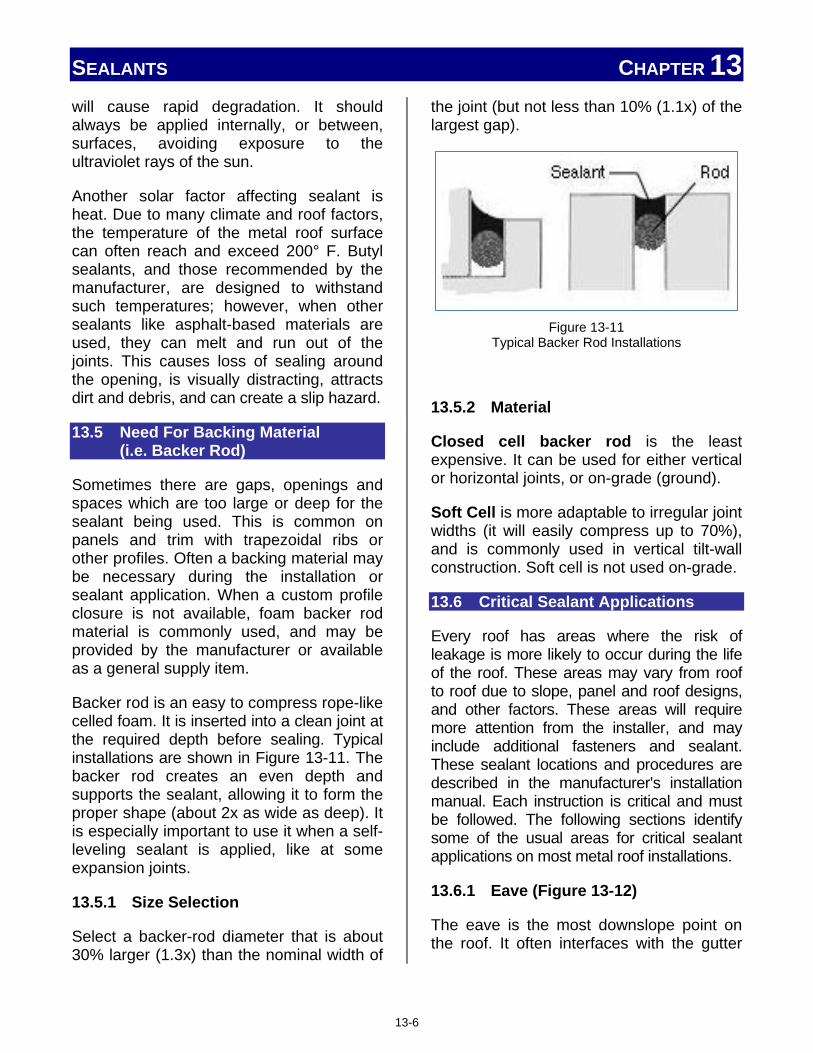
SEALANTS CHAPTER 13 will cause rapid degradation. It should always be applied internally, or between, surfaces, avoiding exposure to the ultraviolet rays of the sun.
Another solar factor affecting sealant is heat. Due to many climate and roof factors, the temperature of the metal roof surface can often reach and exceed 200° F. Butyl sealants, and those recommended by the manufacturer, are designed to withstand such temperatures; however, when other sealants like asphalt-based materials are used, they can melt and run out of the joints. This causes loss of sealing around the opening, is visually distracting, attracts dirt and debris, and can create a slip hazard.
13.5 Need For Backing Material (i.e. Backer Rod)
Sometimes there are gaps, openings and spaces which are too large or deep for the sealant being used. This is common on panels and trim with trapezoidal ribs or other profiles. Often a backing material may be necessary during the installation or sealant application. When a custom profile closure is not available, foam backer rod material is commonly used, and may be provided by the manufacturer or available as a general supply item.
Backer rod is an easy to compress rope-like celled foam. It is inserted into a clean joint at the required depth before sealing. Typical installations are shown in Figure 13-11. The backer rod creates an even depth and supports the sealant, allowing it to form the proper shape (about 2x as wide as deep). It is especially important to use it when a self-leveling sealant is applied, like at some expansion joints.
13.5.1 Size Selection
Select a backer-rod diameter that is about 30% larger (1.3x) than the nominal width of
the joint (but not less than 10% (1.1x) of the largest gap).
Figure 13-11
Typical Backer Rod Installations
13.5.2 Material
Closed cell backer rod is the least expensive. It can be used for either vertical or horizontal joints, or on-grade (ground).
Soft Cell is more adaptable to irregular joint widths (it will easily compress up to 70%), and is commonly used in vertical tilt-wall construction. Soft cell is not used on-grade.
13.6 Critical Sealant Applications
Every roof has areas where the risk of leakage is more likely to occur during the life of the roof. These areas may vary from roof to roof due to slope, panel and roof designs, and other factors. These areas will require more attention from the installer, and may include additional fasteners and sealant. These sealant locations and procedures are described in the manufacturer's installation manual. Each instruction is critical and must be followed. The following sections identify some of the usual areas for critical sealant applications on most metal roof installations.
13.6.1 Eave (Figure 13-12)
The eave is the most downslope point on the roof. It often interfaces with the gutter
13-6
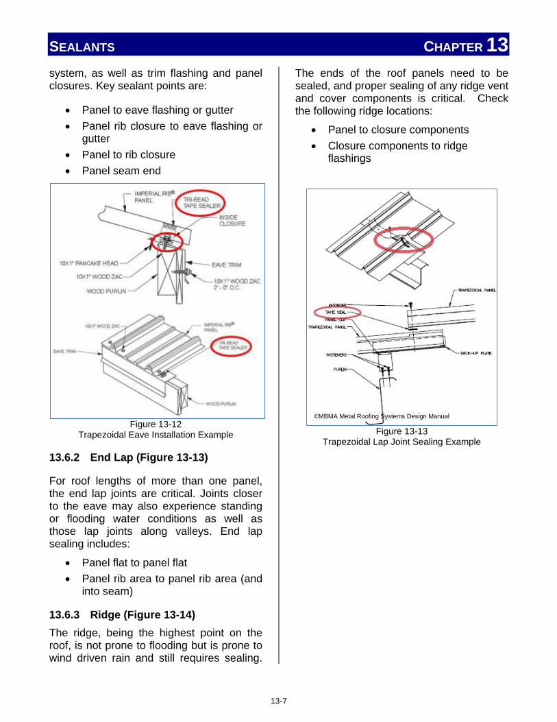
SEALANTS CHAPTER 13 system, as well as trim flashing and panel closures. Key sealant points are:
• Panel to eave flashing or gutter • Panel rib closure to eave flashing or
gutter • Panel to rib closure • Panel seam end
Figure 13-12
Trapezoidal Eave Installation Example
13.6.2 End Lap (Figure 13-13)
For roof lengths of more than one panel, the end lap joints are critical. Joints closer to the eave may also experience standing or flooding water conditions as well as those lap joints along valleys. End lap sealing includes:
• Panel flat to panel flat • Panel rib area to panel rib area (and
into seam)
13.6.3 Ridge (Figure 13-14) The ridge, being the highest point on the roof, is not prone to flooding but is prone to wind driven rain and still requires sealing.
The ends of the roof panels need to be sealed, and proper sealing of any ridge vent and cover components is critical. Check the following ridge locations:
• Panel to closure components • Closure components to ridge
flashings
Figure 13-13
Trapezoidal Lap Joint Sealing Example
©MBMA Metal Roofing Systems Design Manual
13-7
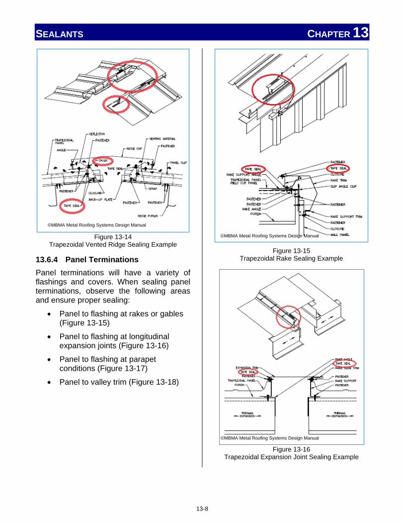
SEALANTS CHAPTER 13
Figure 13-14
Trapezoidal Vented Ridge Sealing Example
13.6.4 Panel Terminations Panel terminations will have a variety of flashings and covers. When sealing panel terminations, observe the following areas and ensure proper sealing:
• Panel to flashing at rakes or gables (Figure 13-15)
• Panel to flashing at longitudinal expansion joints (Figure 13-16)
• Panel to flashing at parapet conditions (Figure 13-17)
• Panel to valley trim (Figure 13-18)
Figure 13-15
Trapezoidal Rake Sealing Example
Figure 13-16
Trapezoidal Expansion Joint Sealing Example
©MBMA Metal Roofing Systems Design Manual
©MBMA Metal Roofing Systems Design Manual
©MBMA Metal Roofing Systems Design Manual
13-8
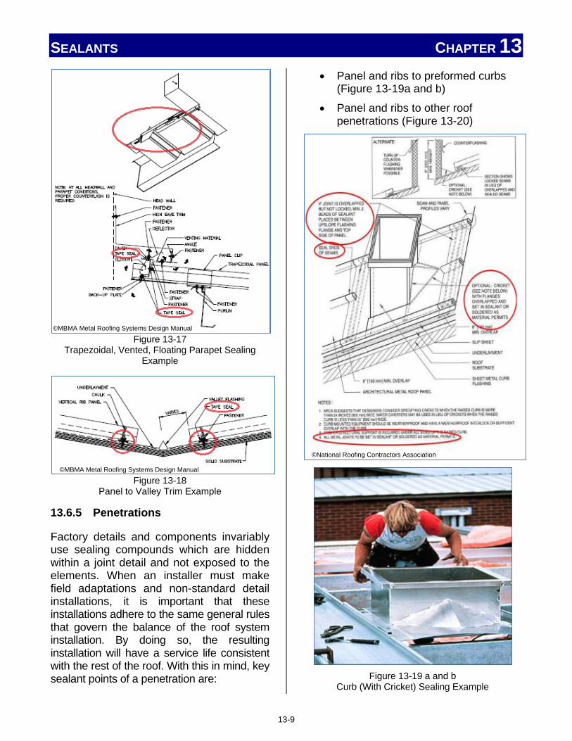
SEALANTS CHAPTER 13
Figure 13-17
Trapezoidal, Vented, Floating Parapet Sealing Example
Figure 13-18
Panel to Valley Trim Example
13.6.5 Penetrations
Factory details and components invariably use sealing compounds which are hidden within a joint detail and not exposed to the elements. When an installer must make field adaptations and non-standard detail installations, it is important that these installations adhere to the same general rules that govern the balance of the roof system installation. By doing so, the resulting installation will have a service life consistent with the rest of the roof. With this in mind, key sealant points of a penetration are:
• Panel and ribs to preformed curbs (Figure 13-19a and b)
• Panel and ribs to other roof penetrations (Figure 13-20)
Figure 13-19 a and b
Curb (With Cricket) Sealing Example
©MBMA Metal Roofing Systems Design Manual
©MBMA Metal Roofing Systems Design Manual
©National Roofing Contractors Association
13-9

SEALANTS CHAPTER 13
Figure 13-20
Roof Penetration Sealing Examples
13.6.6 Flashings
When installing flashing material of any kind, the key points for sealing are:
• Laps of adjacent flashing segments • Lapped joints (Figure 13-21) • Cover plate joints (Figure 13-22) • Concealed plate joints (Figure 13-23)
• Flashings to panels
Figure 13-21
Flashing Lap Joint Sealing ©National Roofing Contractors Association
©National Roofing Contractors Association
13-10

SEALANTS CHAPTER 13
Figure 13-22
Flashing Cover Plate Sealing
Figure 13-23
Flashing Concealed Plate Sealing
13.6.7 Marrying Sealants at Critical Intersections
Note: Indented paragraphs in this section are reprinted with permission from the MBMA Metal Roofing Systems Design Manual).
Sealants are used within low slope, roof systems for several reasons. Two of those reasons are: 1) to protect joints should they become temporarily submersed, and 2) to prevent capillary action from pulling moisture through the joints.
These are demanding conditions for any joint. In order to perform and not leak, sealant continuity is the primary concern. The installer must be sure to "marry" (or blend) adjacent sealant beads. When a bead of sealant is used in this fashion to marry, or meld, two other beads, it is commonly referred to as a "pigtail." For instance, panels are normally sealed at the eave, through its flat area to the eave flashing, gutter leg, or some other flashing component. This is usually done with a butyl tape. In these areas, it is necessary to "marry" sealer as illustrated in Figure 13-24 at the eave, and Figure 13-25 at the ridge.
Figure 13-24
Marrying Sealants at Eave Prevents Leakage
Of course, factory-applied sealant often seals the top of the ribbed seam. Where the seam terminates, (at the panel end) there is a discontinuity of sealant in the vertical
©National Roofing Contractors Association
©National Roofing Contractors Association
13-11

SEALANTS CHAPTER 13 portion of the seam between the factory seal and the tape seal at the panel flat. It is not only vital that the installer seals the two rib surfaces together, but also that he marry this vertical bead of sealant to both the eave tape, and the factory seam sealant. When properly done, as illustrated in Figure 13-26, this will create a continuous gasketed seal at the eave area.
Figure 13-25
Ridge Sealant Example
Figure 13-26
Marrying Sealant Details
The same principals are true when using trapezoidal panels, although the exact details are a bit different due to the use of a rib closure. These are illustrated in Figures 13-27, 13-28, and 13-29.
13-12

SEALANTS CHAPTER 13
Figure 13-27
Closure Sealing of Panel Closure
Figure 13-28
Eave Sealing Details
Figure 13-29
Trapezoidal Eave Detail
There are other areas where the use of pigtails is not only appropriate, but vital. Common examples of such areas are the laps of rake flashings, transition wall flashings, and eave flashings. These have been illustrated earlier in this section. At such areas as these, the objective is to marry the lap seal into the panel seal.
13.6.8 Applying Sealants in Cold Temperatures
Sealants used in a metal roof installation are affected by temperature, both ambient temperature and the actual temperature of the roof material. Sealants have a temperature range for storage, and will act differently when applied in extreme hot or cold temperatures. Refer to information on the container or manufacturer instructions for details and additional conditions.
Butyl compounds are easier to use if they are kept warm during very cold weather, and kept cool during very hot weather. Keeping the material in an ordinary ice chest can do this. Equipping the ice chest with a light bulb and fixture, like the ones shown in Figure 13-30, rigged into the lid makes it into a "warm box".
13-13

SEALANTS CHAPTER 13 During installation, butyl tube sealant may also be used as a lubricant on butyl tape if desired. Because the tack of butyl tape is so tenacious, it sometimes makes panel adjustment and alignment difficult. When laying a panel to a bed of butyl tape, it will adhere quite readily, and not permit lateral adjustment. If the tape is treated with a very thin bead of tube material, the lateral adjustment is facilitated. (The two formats of butyl, tape and tube, are quite compatible.)
Figure 13-30 Coolers and Lamps Keep Sealant Workable In Both
Hot and Cold Temperature Extremes.
Summary
Long life is a prime advantage of a metal roof. Any sealants used during installation must also have a long life. Understanding and using the proper sealants will prevent premature failure of the material. Proper application of the sealant during installation will ensure the roof remains weatherproof and functions as designed.
Notes: ____________________________________________________________________________________________________________________________________________________________________________________________________________________________________________________________________________________________________________________________________________________________________________________________________________________________________
______________________________________________________________________
13-14

Chapter 14: Fasteners Chapter Contents 14. Introduction ...................................................................................................... 14-1
14.1 Fastener Parts and Installation .................................................... 14-1
14.1.1 Points ...................................................................................... 14-1
14.1.2 Heads ...................................................................................... 14-1
14.1.3 Drives ...................................................................................... 14-2
14.1.4 Threads ................................................................................... 14-2
14.1.5 Diameter and Length ............................................................. 14-2
14.1.6 Materials and Coating ........................................................... 14-3
14.1.7 Substructure .......................................................................... 14-3
14.1.8 Installation Key Points .......................................................... 14-4
14.1.9 Stripped Fasteners ................................................................ 14-5
14.1.10 Fastener Identification .......................................................... 14-5
14.2 Fastener Types .................................................................................. 14-5
14.2.1 Nails ........................................................................................ 14-6
14.2.2 Rivets ...................................................................................... 14-6
14.2.3 Screws .................................................................................... 14-6
14.2.4 Clips and Cleats ..................................................................... 14-8
14.3 Attaching Panels – Fastener Spacing and Type .................... 14-9
14.3.1 Through-Fastened Panels ..................................................... 14-10
14.3.2 Concealed Fastener Panels .................................................. 14-11
14.3.3 Standing Seam Panels .......................................................... 14-12
14.3.4 Pre-Drilling Through-Fastened Panels ................................ 14-12

FASTENERS CHAPTER 14
14. INTRODUCTION
Fasteners are a critical component in any metal roof installation. Although the proper fastener is designated by the engineer or designer of the roof system, it is the installer who must actually install it properly. Even the most basic roof system uses hundreds or thousands of fasteners of various sizes, shapes, and styles. Fasteners may appear similar but differ greatly in their performance. Always use the manufacturer's recommended fastener size and type. Doing so protects the design performance of the installation.
The designated fastener is selected based on such factors as the material and thickness of the roof panel, insulation, substrate, and structural members of the roof system. Other factors like wind resistance and roof load are also used in determining the correct fastener for the installation.
Sometimes a fastener substitution must be made. The installer must often select and install an acceptable substitution. The material in this chapter will provide a solid foundation for making a decision which will not compromise the integrity of the roof system.
14.1 Fastener Parts and Installation
Selecting and using the best fastener during the installation makes the installer's job easier and faster, with lower installation torques and faster installation times. The choice of the best fastener also helps by reducing labor costs and improving overall roof system performance.
Today's fasteners save installation time by eliminating steps like drilling, tapping, and sealing by their unique design features. Most of the fasteners the installer uses are a "self" style fastener; self-piercing, self-drilling, self-cutting, and even self-tapping.
A typical metal roof fastener is illustrated in Figure 14-1 and the key areas are identified. These areas will be discussed in light of the installer's normal activities and requirements.
Figure 14-1 Key Areas of a Typical Fastener
14.1.1 Points
The points of the fastener will vary based on their design function. Self-piercing, drilling, and cutting fasteners all have different points and are illustrated in Figure 14-2.
Figure 14-2
Fastener Points
Self-piercing fasteners are used with lighter gauge materials, while self-cutting or self- drilling points are used with thicker gauge and more solid materials, substrates, and structural members. Screw points may be combined with other fastener types. Each manufacturer will have specific combinations best suited for the installation.
©MBMA Metal Roofing Systems Design Manual
14-1

FASTENERS CHAPTER 14 14.1.2 Heads
The proper head style ensures stability during driving, proper clamping of materials, and desired finish appearance. Figure 14-3 shows some of the many fastener head styles used in metal roof installations. Heads that are designed as flat, flush, or even countersunk are normally installed as concealed fasteners and covered with other roof members or within narrow spaces. Domed, hex, rounded, or pan-head style fasteners are designed to remain above the fastened member's surface, often exposed to the environment.
Figure 14-3
Fastener Heads
In roofing applications, many fasteners have some sort of gasket or seal beneath the head surface. When installing a sealed fastener, it is a good practice to visually look at each fastener as it is being connected to the drive bit. Sealed fasteners should not be over-tightened or seal damage and leaking may occur.
14.1.3 Drives
How the fastener is "driven" or "attached" to the system can vary, and new varieties continue to be introduced. Some of the more common drive styles are shown in Figure 14-4. Drives vary from the traditional slotted and Phillips screw styles to elaborate combinations requiring special bits for installation.
Drive formats may be combined with other fastener types discussed in this section.
Certain drive styles are more common to concealed fasteners, while others are typical for through-fastener applications.
Figure 14-4
Fastener Drives
14.1.4 Threads
The correct choice of thread form and diameter optimizes low installation torque with high pullout strengths. The thread surface is one portion of the fastener which is in direct contact with the material, and provides the transfer of loads, while sustaining the holding pressure for the fastened material. Traditional thread sizes (Figure 14-5) are used, but the strength of the fastener is determined by the selected thread size, along with the fastener diameter, its length, and the fastener material.
Figure 14-5
Most Fasteners Use Standard Thread Sizes
The fastener is then selected to match the requirements for the specific roof installation and the material to which the fastener is attached. It should be noted that only threads which are actually engaged in material are adding value and strength to the system. Any exposed threads which protrude through material, or within a void, are not adding to the holding strength of the fastener.
14.1.5 Diameter and Length
The diameter and length of the fastener, in combination with the thread size and
14-2

FASTENERS CHAPTER 14 material, determine its strength. Generally bigger and longer is stronger, but as mentioned in the thread discussion, only the portion of the material in direct contact with other material is significantly adding to the holding strength of the fastener.
14.1.6 Materials and Coatings
The fastener finish provides lubrication during installation, as well as corrosion resistance after installation. The material of the fastener determines the initial fastener strength when all other factors are equal. The fastener material and its coatings are a concern to the installer for another very important reason: compatibility.
Installing fasteners of the wrong material or coating, might not weaken the strength of the roof, but certainly can shorten the life of the roof by dissimilar metal corrosion and staining of the roof materials as shown in Figure 14-6. Material compatibility is explained in more detail in Section 3.6, Compatibility, and Section 10.9.3, Dissimilar Materials. Check with fastener, roof panel, and substrate manufacturers for corrosion resistance requirements and information.
Figure 14-6
Incorrect Fastener Material Shortens Roof Life
Fasteners for a roof installation are supplied with a variety of coatings. Because of oxidation, carbon steel fasteners have some type of coating (e.g., zinc, proprietary) applied to the fastener. Exposed fasteners, except for unique situations, should always match
the color of the roof panel being installed. Fasteners which do not match the color of the roof panel can create issues like those shown in Figures 14-7 and 14-8. Fasteners of these types are normally ordered directly from the roof panel manufacturer, and in quantities which allow for extras.
Figure 14-7
Wrong Color Fasteners Installed on a Roof Panel
Figure 14-8
Correct Color Fastener Next to Incorrect Fastener Note – Premature Corrosion on Incorrect Fastener
14.1.7 Substructure
The substructure, its thickness, and its material are prime factors in the selection of an appropriate fastener. Substrate thickness primarily affects a fastener's required length, while the substrate material factors into the fastener coating, material, size, thread, and point characteristics. For example, a fastener installed into steel deck or a concrete member would not be the same fastener used if the deck were 1" treated wood.
When treated wood is the substrate, the following fastener recommendations are suggested:
14-3

FASTENERS CHAPTER 14
Carbon steel, aluminum, and electroplated galvanized steel fasteners and connectors should not be used in contact with treated wood. Hot-dipped galvanized fasteners generally are acceptable. Stainless-steel fasteners and connectors are recommended for maximum corrosion resistance.
Fasteners with proprietary anti-corrosion coatings may be acceptable for use with treated wood. When considering the use of such proprietary-coated fasteners and connectors, consult the fastener manufacturers for specific information regarding the performances of their products
in treated wood and any precautions or special Instructions that may be applicable.
Aluminum fasteners, flashings and accessory products should not be used in direct contact with any treated wood. ACQ-treated wood is not compatible with aluminum. See the Recommended Fastener Guide above for more information.
14.1.8 Installation Key Points
Drill and pierce points can leave a sliver of panel material which, if caught by the washer, may damage the washer, allow water intrusion and premature corrosion.
14-4

FASTENERS CHAPTER 14 There are two characteristics a fastener must have for proper installation. It must be straight, and it must be tight, like those illustrated in Figure 14-9.
Figure 14-9
Properly Installed Fasteners Are Straight and Tight
When a fastener is not straight, the head does not seat properly to the surface. This results in gaps which may leak and not seal properly. The head of the fastener is also responsible for holding the material in place. When not seated properly, there is less surface and uneven pressure holding the material in place. This creates a weaker connection which may fail at a later time or under additional stresses.
Any fastener can be installed to the improper tightness. Fasteners can be under-tightened or over-tightened. Under-tightened fasteners, like the one shown in Figure 14-10, do not seal properly and are likely to leak. They also do not provide the strength needed to hold the material in place.
Figure 14-10
Under-Driven Fastener
This allows the material to move when it should remain in place. This additional movement may cause distortion, damage the material, and cause roof failure. Under-tightened fasteners are typically and easily corrected by retightening to the correct tightness.
Over-tightened fasteners present more of a problem and are more difficult to correct. When a fastener is over-tightened, it deforms and often distorts the material it is holding in place. As seen in Figure 14-11, this can create pockets for moisture and water which easily corrode the metal panels and may potentially leak. Over-tightening often over-compresses gaskets and sealant used along with the fastener. This causes less sealing ability around the fastener.
Figure 14-11
Over-Driven Fastener Note- Distortion and Pocket for Moisture
Correcting over-tightened fasteners is not a matter of simply "untightening", or "loosening," the fastener, because this will create gaps and loss of holding pressure. Replacing over-tightened fasteners may involve additional sealant, a change in gasket, and a different size fastener being used as a replacement. Panel replacement may be necessary if distortion or damage is too severe.
14.1.9 Stripped Fasteners
Fastener technologies are constantly improving A stripped fastener is a common result of over-tightening. New head and
14-5

FASTENERS CHAPTER 14 washer designs make over-tightening almost impossible, but occasional stripping of screws or washer damage is inevitable. Stripped fasteners no longer have the material or the holding pressure present in order to properly secure and seal the area surround the fastener's point of installation. Stripped fasteners must be replaced.
When this happens, the correct remedy is to replace the screw. It is never acceptable to repair such a defect by the surface application of sealant at the screw location. If the problem is merely washer damage, the screw should be replaced with one of like size. If the fastener has stripped, an over-sized screw should be used as a replacement. The installer should have a few over-sized screws at all times when using a screw gun. This will ensure that the remedy is immediately at hand when the mishap occurs, and increases the odds that the fix will be prompt and proper. It is also a good idea to have a few oversized sealing washers on hand, just in case. These can be obtained from the roof manufacturer or most fastener distributors.
14.1.10 Fastener Identification
Installers and others working in the trade often have short names for most fasteners and are often confused when checking Material Lists, Installation Instructions, or the Bill of Materials (BOM) when fasteners are listed. Because of the vast variety of fasteners, many similar in appearance, a standard method of listing fasteners has been established to eliminate confusion. An example is listed in Figure 14-12.
Figure 14-12
Typical Listing Method for Fasteners
This listing identifies each key characteristic of the fastener previously discussed. Additional information is often added, such as a supplier identification number or part number for ordering the fastener. When colored fasteners are identified, a color, initials, or several additional numbers or letters are added to specify the color.
14.2 Fastener Types
The most common types of fasteners used for metal roofing installations are nails, rivets, screws, clips, and cleats. Most installations will use a variety of each of these types of fasteners. However, the amount of each type of fastener will vary greatly, based on the type of roof panel being installed.
14.2.1 Nails
Nails are installed by driving the fastener into a substrate, normally wood, by impact, typically with a hammer or powered impact tool. Nails are the most used fastener in asphalt based roofing materials. Nails, like those shown in Figure 14-13, are sometimes used in select metal roof installations, especially for underlayment, slip sheets, and wood substrates. Nails also are frequently used when wood purlins and nailers are installed on the roof system.
14-6

FASTENERS CHAPTER 14
Figure 14-13
Typical Nails Sometimes Used in Metal Roof Installation
14.2.2 Rivets
Rivets, pop rivets, or blind rivets are small non-threaded fasteners with an expandable head for joining light-gauge sheet metal. This type of fastener, like those shown in Figure 14-14, is popular within all sheet metal applications, and provides quick, neat installations. It does, however, require that a hole be drilled through all pieces of material being joined by the fastener.
When installing pop-style rivets, an installer must pay attention to these key fastener dimensions: the drill and rivet diameters, and the "grip" or "pull-up" dimension of the rivet being installed. If either of these dimensions is too great or too small, the joint will not have the strength intended.
Figure 14-14
Rivet Examples
Most standard rivets are not designed to withstand leaks. Special design rivets may be specified which do provide leak protection. The rivet type of fastener does
require a special tool, like the one shown in Figure 14-15, for proper installation. These are normally hand-operated, but pneumatic rivet tools are sometimes used when convenient, and a large amount of rivets must be installed. This tool is discussed and explained in more detail in Section 12.7, Rivet Gun.
Figure 14-15 Hand Held Rivet Tool
14.2.3 Screws
Screws of all types are the most used fastener on a metal roof system. The specific type of screw required depends on the type of panel being installed and the material to which it is being fastened. The size and length of the screw will vary, even within the same roof installation. Many of the screws used on a roof installation have seals or gaskets.
Self-piercing screws, sometimes called sheet metal screws, have a very sharp point as seen in Figure 14-16. Designed for fastening lighter gauges of sheet metal, the sharp point easily punctures the material, eliminating the need for drilling.
Figure 14-16
Self-Piercing Screw
14-7

FASTENERS CHAPTER 14 Self-drilling screws, also called TEK screws, are similar to sheet metal screws, but with a "drill bit-style" point that drills its own pilot hole. The drill bit end, illustrated in Figure 14-17, is better suited for penetrating and opening thicker gauge sheet metal and other structural material.
Self-drilling screw sizes are available from number 1 through number 5 points. The self-drilling screw sizes are selected based on the combined substrate thickness. The higher the number, the thicker material the drill is designed to penetrate.
Figure 14-17
Self-Drilling Screw
When fastening with self-drilling fasteners, it is imperative that the screw point has cleared the substrate before the threads engage or the driller will actually pull the threads through the substrate faster than it can be drilled, thereby breaking the fastener. This is illustrated in the steps shown in Figure 14-18. The recommended diameter and threads per inch will vary based on the desired fastener performance and substrate thickness.
Figure 14-18
Drill Bit Must Clear Substrate Before Threads Engage
Self-cutting screws (Figure 14-19) are similar to self-piercing and self-drilling screws, but cut, rather than pierce or drill, their own holes.
Figure 14-19
Self-Cutting Screw
Self-tapping screws (Figure 14-20) are designed to cut their own threads into the fastened material and maintain a tight grip between attached materials. True "self-tapping screws," like the middle fastener in Figure 14-19, require a pilot hole for installation; however, self-tapping threads are normally combined with self-piercing, drilling, or cutting points for a versatile fastener which is widely used across the construction industry.
Figure 14-20
Self-Tapping Screws
14.2.4 Clips and Cleats
Clips are normally the fastener used for attaching the roof panel to the substrate or deck on a concealed fastener metal roof system. Clips are also used in a variety of other applications within the roof system. Most clips are designed and supplied by the roof system manufacturer specifically for a single type of roof panel. Common clip examples are shown in Figure 14-21 along with a typical installation. Clips are designed to firmly hold the panel in place, or to allow thermal movement of the panel. Clips may also vary depending on the amount of wind-lift protection required. When clips are used with rigid insulation, a different style clip may be required or bearing plates used for additional support. An example of this type of
©MBMA Metal Roofing Systems Design Manual
14-8

FASTENERS CHAPTER 14 installation is shown in Figure 14-22. Note the longer fasteners and baseplates required for each clip.
Figure 14-21
Common Clip Styles and Installation
Cleats are also used for fastening roof members, normally along the roof edge and areas of trim, flashing and gutter installations. While clips are smaller, individual fasteners, cleats are normally longer and sometimes formed on-site. Clips may be one-piece or multi-piece fasteners, while cleats are a single formed piece of material. Both clips and cleats are designed to be concealed and are not normally visible after installation. Figures 14-23 and 14-24 illustrate common cleat applications and profiles.
Figure 14-22
Clips Installed Over Rigid Foam May Require Different Fasteners and Base Plates
Figure 14-23
Fastening Details of Cleats
©MBMA Metal Roofing Systems Design Manual
©National Roofing Contractors Association
©National Roofing Contractors Association
14-9

FASTENERS CHAPTER 14
Figure 14-24
Typical Cleat Installation
Installer Note
Fastener Handling Care should always be used when handling the fasteners for a metal roof system. Nails, screws, and rivets are small and are easily dropped. They are often a cause of tire damage on jobsite vehicles, can cause corrosion and staining on the roof surface, and jams in the drainage system.
Clips and cleats are quite strong when properly installed, but are easily bent and damaged before installation on the roof. Stepping on a clip or fastener which has been dropped will likely damage the clip and may dent, or even puncture the roof surface.
Always give extra attention when handling fasteners, especially where larger quantities, or "handfuls," are being handled at one time.
14.3 Attaching Panels – Fastener Spacing and Type
Before discussing the attachment of specific types of panels, there are several key points to mention which are common to every panel type.
The spacing of fasteners will vary based on several factors. Geographic and weather conditions will determine spacing and type of fastener. A roof that must withstand stronger, even hurricane force winds will have more fasteners, and the fasteners will be installed closer together than on a roof designed for a less forceful environment.
Spacing and fastener types will vary within the roof itself. Certain portions of the roof experience different stress levels and may require additional support. This is illustrated in Figure 14-25 and explained in more detail in Section 10.2, Uplift.
Figure 14-25 Different Roof Areas Experience
Different Uplift Stresses
This is why fasteners along the eaves and ridges often differ from those along panel seams. Side seams along the gable ends will often have more fasteners than those seams
©MBMA Metal Roofing Systems Design Manual
©National Roofing Contractors Association
14-10

FASTENERS CHAPTER 14 which are mid-roof. Some panels, especially longer panel types, have different fastener patterns at the panel ends than at the mid-panel.
The substrate material and strength (thickness) will also be a factor in the spacing and type of fastener. A roof installed over a thick, solid deck may require fewer, further spaced fasteners than a roof over open spacing. A roof installed over widely spaced structure members is naturally limited in the number, and location, of fasteners which may be installed.
An installer should always follow the manufacturer's recommended instructions for installation methods, and the type, spacing, and location of all fasteners.
14.3.1 Through-Fastened Panels
Attaching through-fastened panels requires additional care during installation because holes must be made through the panel at each fastener location. Each hole has the potential to leak if the correct fastener is not properly installed and sealed. Through-fastened panels normally require fasteners with seals and additional sealant, and additional fasteners along the eaves and lower-end drainage portions of the roof. Typical through-fastened panel installations are shown in Figures 14-26, 14-27 and 14-28.
Figure 14-26
Through Panel Fastener Pattern at Eave and Endlap Locations
Figure 14-27
Through Panel Fastener Pattern at Mid-Panel Locations Note- Only 3 Fasteners Required
Figure 14-28
Through Panel Fastener Lap Joint
As shown in Figure 14-28, some panels have alternate methods of attachment. It is critical that every installer on the job understands and follows the same method and pattern of panel installation. An installer should not interchange these methods within the same area in order to avoid creating appearance issues.
Figure 14-29
Through Panel Alternate Fastener Pattern Note – Fasteners Installed at Rib Peaks
Another concern to the installer is that the fasteners of a through-fastened panel roof are highly visible and part of the finished
14-11

FASTENERS CHAPTER 14 roof appearance. Any fastener installation errors, such as alignment, color, repairs, or "extra" fasteners, will be visible and could become an issue. Figure 14-30 shows how the wrong color fastener affects the final appearance of the roof. Additionally the wrong fastener material was used, quickly rusted, and stained the roof. Figure 14-31 shows a close up and the correct fastener which should have been installed.
Figure 14-30
Color and Alignment Errors in Fastener Installation are Very Visible
Figure 14-31
Correct Fastener Compared to Installed Fastener
In this method of installation, "neatness counts," and every fastener must present a uniform appearance which "fits" with the entire roof installation.
14.3.2 Concealed Fastener Panels
Attaching concealed fastener panels relies heavily on the use of special clips, cleats and fasteners which are not visible after the roof installation. These are highly dependent on the panel design and profile.
Typical clip installations are illustrated in Figures 14-32 and 14-33. Few, if any, exposed fasteners are used. When necessary, these exposed fasteners are normally limited to the eaves, ridges, or unique areas with special requirements.
Figure 14-32
Concealed Fastener, Trapezoidal Rib Panel Installation
This type of installation requires additional attention from the installer when sealing the panel and spacing the fasteners. Clips are normally spaced closer together at the panel ends (the eave and ridge areas) and further apart at the mid-section of the panel. Clip spacing may also be different at the
©National Roofing Contractors Association
14-12

FASTENERS CHAPTER 14 gable ends or where installing a less-than-full-width panel. Different sealing requirements may occur at clip locations due to thermal movement of the panel. Often this type of panel has factory installed sealant at the seams, but still requires additional sealant and proper "marrying" of the sealant. (See Section 13.6.7, Marrying Sealants at Critical Intersections.)
Figure 14-33
Concealed Fastener, Standing Seam Panel Installation
14.3.3 Standing Seam Panels
Standing seam roof (SSR) installations rely heavily on hidden fasteners and clips along the seams, and exposed fasteners along eaves and other locations. The installed clips are often bent and formed along with the panel when the seam is formed, normally by a mechanical seamer. These steps are illustrated in Figure 14-34. An important point for the installer to remember is that the rolled or formed seam normally bonds
and forms the individual panels into one roof membrane, while the purpose of the clips and most of the installed fasteners is to fasten and secure the roof membrane to the structure. Some installations may also require some form of mastic or sealant to be applied between panel seams. While the panel profiles and clip configurations will vary, most standing seam roof panels are installed as illustrated previously in Figures 14-32 and 14-33.
Figure 14-34
When Rolled, the Clip Becomes Part of the Seam
14.3.4 Pre-Drilling Through-Fastened Panels
Extreme care must be used if pre-drilling any roof panel prior to locating the panel in its final position. While pre-drilling panels may save labor time, allow multiple panels to be drilled at once, and maintain identical fastener patterns between panels, careful consideration must be given to the potential problems arising from panel alignment:
• Panel to other panels
• Panel straightness to roof edge
• Panel to structural members (on an open framing system)
©National Roofing Contractors Association
©National Roofing Contractors Association
14-13
FASTENERS CHAPTER 14
• Alignment problems due to differing fastener patterns around less than entire panel sections.
Sometimes a panel must be drilled and additional fasteners installed after the initial panel installation. This may be due to an accessory installation, roof mounted equipment, additional flashing, trim, or repairs. When this is necessary, the installer must avoid double pinning of any panel, and plan on proper sealing of the area around the additional fasteners and material. A different installation method and procedure is often necessary after the initial panel installation. Other installer precautions include making sure all drilled holes and drilling residue is cleaned up and removed and that pre-drilled holes should not remain open and exposed for an extended period of time.
Summary
Every roof installation requires hundreds, and sometimes thousands, of fasteners. Each fastener is installed individually, and is expected to perform as designed, not leak, and last the lifetime of the roof. It is the installer's responsibility to install the correct fastener, install it properly, and install it in the correct location. The best way to ensure this happens is by under-standing and following the manufacturer's instructions.
Notes: _________________________________________________________________________________________________________________________________________________________________________________________________________________________________________________________________________________________________________________________________________________________________________________________________
_____________________________________________________________________________________________________________________________________________________________________________________________________________________________________________________________________________________________________________________________________________________________________________________________________________________________________________________________________________________________________________________________________________________________________________________________________________________________________________________________________________________________________________________________________________________________________________________________________________________________________________________________________________________________________________________________________________________________________________________________________________________________________________________________________________________________________________________________________________________________________________________________________________________________________________________________________________________________________________________________________________________________________________________________________________________________________________________________________________________________________________________________________________________________________________________________________________________________________________________________________________________________________________
14-14

Chapter 15: Seam Joining Chapter Contents
15. Introduction ...................................................................................................... 15-1
15.1 Overlaps ............................................................................................... 15-1
15.2 Snap Seams ........................................................................................ 15-4
15.3 Mechanical Seams ............................................................................ 15-4
15.4 Critical Components ........................................................................ 15-5
15.4.1 Sealant .................................................................................... 15-5
15.4.2 Side Lap Fastening ................................................................ 15-6

SEAM JOINING CHAPTER 15
15. INTRODUCTION Metal panels are designed not to leak when used in the appropriate application and installed properly. The joining of roof panels to each other and to trim and flashing pieces is a major and critical part of any installer's work.
Important Note: Different types of seams require specific installation techniques. The information provided in this manual does not supersede installation instructions provided by the manufacturer. Always consult the manufacturer's instructions and/or detailed shop drawings for information specific to each project.
Additional important and necessary seam joining information for the installer can be found in other sections of this manual:
• Chapter 4, Panel Types
• Chapter 5, Side Joint Configuration
• Chapter 7, Panel Connections
• Chapter 12, Tools and Field Operations
• Chapter 13, Sealants
• Chapter 14, Fasteners
• Chapter 16, Panel Installation
Every installer should understand this additional material prior to attempting the seam joining mentioned in this chapter.
There are many methods of joining adjacent sections of sheet metal. The following information will focus on the most commonly used types of seams, and key points for installers to remember in performing their work.
15.1. Overlaps
The simplest and most basic seam is the lap joint. This style joint is commonly used for flashings and end joints in long panels which are not located at the eave or ridge sections of the roof. The basic lap joint is nothing more than a portion of the up-slope panel lying on top of, or "over-lapping," a lower, downslope panel. This is illustrated in Figure 15-1. The best practice on this type of joint includes the application of an appropriate sealant at each joint.
Figure 15-1
The Basic Lap Joint
A variation of the lap joint is the nested lap, which is utilized by many types of ribbed metal panels. A nested lap joint overlaps the adjacent panel, but also covers or "nests" the lower panel rib within the rib of the lapping panel. This is the seam joint shown in Figure 15-2.
Figure 15-2
The Nested Lap Joint
The important thing to remember when using a lap joint is that water doesn't always run downhill. Capillary action may also take place. Whenever two surfaces are adjacent to each other, the small gap of the joint changes the properties of the run-off liquid. The liquid may be siphoned up-slope, between the panels as illustrated in Figure 15-3.
© Rob Haddock, all rights reserved
© Rob Haddock, all rights reserved
15-1

SEAM JOINING CHAPTER 15
Figure 15-3
Capillary Action Between Roof Panels
This capillary action will cause water to run upslope and beneath the roof panel if corrective action is not taken. One corrective action involves a design change in the panel profile and is added during the manufacturing of the panel. Two other possible corrective actions are taken during installation of the panel.
Panels designed to be installed with a nested lap joint may have a capillary groove formed into the upper portion of the rib as illustrated in Figure 15-4. This groove is designed to "break" the capillary action of the water and provide a channel for the water to drain away from the protected area.
Figure 15-4
Addition of a Capillary Groove to a Nested Seam
When these nested panel seams use external fasteners, EXTREME CARE SHOULD BE USED during the installation of these panels to prevent damage to the panel and leakage after installation. Often these panels will require fasteners, nails, or screws to be installed off-center on the rib. While this appears unusual, it is necessary
in order to prevent puncturing or damaging the drainage channel within the seam. This can be clearly seen in the examples shown in Figure 15-5. Following the manufacturer's installation patterns will avoid damage, leakage, and warranty issues in this area.
Figure 15-5 Fastener Pattern Examples for Nested Seam Panels
© Rob Haddock, all rights reserved
© Rob Haddock, all rights reserved
15-2

SEAM JOINING CHAPTER 15 There are also two corrective actions which can be taken during installation to prevent leakage of the lap joint, both of which involve the use of sealant.
The basic lap joint is usually given a layer of sealant between the panels, slightly up-slope of the panel edge, as illustrated in Figure 15-6.
Figure 15-6
Sealant Application within a Basic Lap Joint
This sealant is usually applied in tape format, and is applied in such a way as to avoid outside exposure to the sun and environment. It is also installed so the joint and sealant are compressed by the fasteners holding the panels. When fasteners are installed in a sealed lap joint, it is critical that the fasteners be installed on the dry side of the sealed joint, usually so the fastener goes through, and is surrounded by, the compressed sealant as shown in Figure 15-7.
Figure 15-7
Typical Panel Endlap Joint Showing Sealant and Fastener Details
When sealant is used on a nested lap joint with no capillary groove, it is installed as shown in Figure 15-8. Note that the sealant is applied on the side of the fastener closest to the outside edge of the top panel.
Figure 15-8
Sealing of Nested Seam Lap Joint
When a nested lap joint is located in an area that may experience standing water or flooding above the joint seam, the joint is often sealed, even when the panel has a capillary groove as part of its design. The sealant is applied in the same location as previously mentioned, and is illustrated in Figure 15-9.
Figure 15-9
Sealing of Grooved Nested Lap Joint When There Is Potential Flooding of Seam
Always use the manufacturer's recommended sealant during an installation, as well as the locations and spacing requirements called out on plans and instructions.
Installer Precaution
As detailed in Chapter 13, Sealants, alternate sealant procedures are used when lap joints used additional cinch straps. Always follow Manufacturer's instructions for sealant and fastener placement.
© Rob Haddock, all rights reserved © Rob Haddock, all rights reserved
© Rob Haddock, all rights reserved
15-3

SEAM JOINING CHAPTER 15 15.2 Snap Seams
Snap seams are usually simple to install and come in a variety of profiles. Some profile varieties are displayed in Figure 15-10.
Figure 15-10
Snap Seam Profile Examples
Traditional fasteners and clips are used to secure the panel to the deck or roof system, but the between-panel seams are "snapped" together as shown in Figure 15-11. The snap seam is usually used on standing seam or batten-style panes, and may use separately attached caps, or integrate caps for covering the seam.
Figure 15-11
Snap Seams on Standing Rib and Batten-Style Panels
This cap, or batten, snaps on to an adjacent panel's rib or clip to complete the seam. Male and female legs, as shown in Figure 15-12, are joined to secure the seam in place. Installers should note that some panel designs snap into place easier than others. It is critical that the entire panel seam is securely snapped and engaged in place.
Individual battens must also be secured to avoid sliding, normally under the ridge cap.
Some snap-cap or batten-cap seaming systems have relatively poor water resistance. This often restricts their use to steep-slope, architectural applications.
Figure 15-12
Proper Engagement of Snap Seam Joint
15.3 Mechanical Seams Mechanical seams are joined together by using hand-seamers, tongs, or electrical seaming devices. These tools, as discussed in Section 12.9 Seaming Tool, can turn a seam completely over itself, producing a weatherproof seam similar to a traditional double-locked seam. Other seam configurations may be partially crimped or folded to produce the desired result. See Figure 15-13.
Figure 15-13
Mechanically Formed Seams
©National Roofing Contractors Association
©National Roofing Contractors Association
15-4

SEAM JOINING CHAPTER 15 Mechanically formed seams tend to remain firmly attached to the roof structure. This is because, in many cases, the panel clip is also folded over and becomes part of the rolled seam. This is illustrated in Figure 15-14.
Figure 15-14
Steel Beam Mounted Panel Clip for Use with a Mechanical Seam
15.4 Critical Components
The critical components discussed in this section, sealant and stitching, are critical to each installation. No matter which seam joining method is used, the same key points of each of these components apply.
15.4.1 Sealant
When sealant is used during the seam installation, the sealant type, amounts, and location are key factors for the installer to consider. Sealant is detailed in Chapter 13, and should be reviewed as part of understanding this critical component. Some sealant highlights will be repeated here for clarity.
When required, most metal panel seams will use a butyl-type sealant. This sealant remains sticky, does not harden, nor "skin-over." It should always be installed between
the metal surfaces and never externally applied as shown in Figure 15-15.
When sealant is used in a seam joint, it is often compressed by the fasteners and clips used to secure the panel. The installer should make sure that, when the joint is compressed, no sealant is squeezed out and is exposed on the roof surface. Butyl sealant quickly deteriorates when exposed to the ultraviolet rays of the sun. Exposed butyl sealant will also smear, gather dust and dirt, and mar the appearance of the roof surface.
Figure 15-15
Butyl Sealant Should NOT be Externally Applied
The amount of sealant used must also be controlled by the installer. This is easily done when a tape format sealant is used, but more challenging when tube-format sealant is required. Excess sealant may be squeezed onto the roof surface or distort the roof surface. During any sealant application, any excess sealant should be quickly removed, and the surface cleaned using approved cleaning materials.
Sealant location is important, especially when fasteners are used. Fasteners must be located and installed in the correct relationship to the applied sealant. This relationship is illustrated in Figure 15-16 and follows most installation and manufacturer recommendations.
© Rob Haddock, all rights reserved
15-5

SEAM JOINING CHAPTER 15
Figure 15-16
Fastener and Sealant Orientation at the Seam
15.4.2 Side Lap Fastening
On through-fastened type panels, joining is the process of attaching, or seaming, thin sheet metal panels to other thin sheet metal panels, or to thin metal trim or flash pieces. Short "sheet metal screw"-style fasteners, called lap screws, are used. These fasteners are often referred to as "stitching" screws. While primary fasteners are used to secure the panels, plus with-stand various roof loads, stitch fasteners are only used to secure the thin sheet metal components to each other. This difference and typical fastener locations are illustrated in Figure 15-17.
Figure 15-17
Locations of Primary and Stitch Type Fasteners
Caution should be used when installing stitch fasteners. They are easily stripped, and must be replaced with a different size fastener when this occurs.
Summary
The joining of roof panels is a major and critical part of any installer's work. Proper joining of the roof seams allows the roof membrane to act as a single unit, protect the area beneath the roof, and perform as designed.
Installer Note
The information provided in this manual does not supersede installation instructions provided by the manufacturer. Always consult the manufacturer's instructions and/ or detailed shop drawings for information specific to each project.
Notes: _____________________________________________________________________________________________________________________________________________________________________________________________________________________________________________________
15-6

Chapter 16: Panel Installation Chapter Contents 16. Introduction ...................................................................................................... 16-1
16.1 Coordination and Sequencing With Other Trades ................ 16-1
16.2 Checking the Structure – Substructure .................................... 16-2
16.2.1 Squareness .............................................................................. 16-2
16.2.2 In-Plane Alignment ................................................................. 16-4
16.2.3 Flatness ................................................................................... 16-5
16.3 Determining Direction and Sequence of Installation ........... 16-6
16.3.1 Prevailing Winds ..................................................................... 16-7
16.3.2 Panel Layout ............................................................................ 16-7
16.3.2.1 Single Panel Eave To Ridge .................................. 16-8
16.3.2.2 Multiple Panels Eave To Ridge ............................. 16-8
16.4 Maintaining Panel Modularity and Alignment ......................... 16-8
16.4.1 Starting Square to the Eave ................................................... 16-9
16.4.2 How To Measure and Check During Installation .................. 16-9
16.4.3 Results of Failure .................................................................... 16-10
16.4.3.1 Sawtoothing At Eave, End Laps, and Ridge ........ 16-10
16.4.3.2 Aesthetics of Alignment........................................ 16-11
16.4.3.3 Finish Rake Issue .................................................. 16-13
16.4.3.4 Thermal Movement Issues .................................... 16-13
16.4.3.5 Sealant Issues at End Laps, Eaves, and Ridge ... 16-14
16.4.4 Tolerances ............................................................................... 16-16
16.5 Field Operations ................................................................................ 16-18
16.5.1 Field Cutting of Panels and Trim ........................................... 16-18
16.5.2 Brake Forming ......................................................................... 16-19
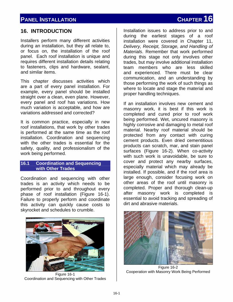
PANEL INSTALLATION CHAPTER 16
16. INTRODUCTION Installers perform many different activities during an installation, but they all relate to, or focus on, the installation of the roof panel. Each roof installation is unique and requires different installation details relating to fasteners, clips and hardware, sealant, and similar items.
This chapter discusses activities which are a part of every panel installation. For example, every panel should be installed straight over a clean, even plane. However, every panel and roof has variations. How much variation is acceptable, and how are variations addressed and corrected?
It is common practice, especially in new roof installations, that work by other trades is performed at the same time as the roof installation. Coordination and sequencing with the other trades is essential for the safety, quality, and professionalism of the work being performed.
16.1 Coordination and Sequencing with Other Trades
Coordination and sequencing with other trades is an activity which needs to be performed prior to and throughout every phase of roof installation (Figure 16-1). Failure to properly perform and coordinate this activity can quickly cause costs to skyrocket and schedules to crumble.
Figure 16-1
Coordination and Sequencing with Other Trades
Installation issues to address prior to and during the earliest stages of a roof installation were covered in Chapter 11, Delivery, Receipt, Storage, and Handling of Materials. Remember that work performed during this stage not only involves other trades, but may involve additional installation team members who are less skilled and experienced. There must be clear communication, and an understanding by those performing the work of such things as where to locate and stage the material and proper handling techniques.
If an installation involves new cement and masonry work, it is best if this work is completed and cured prior to roof work being performed. Wet, uncured masonry is highly corrosive and damaging to metal roof material. Nearby roof material should be protected from any contact with curing cement products. Even dried cementitious products can scratch, mar, and stain panel surfaces (Figure 16-2). When co-activity with such work is unavoidable, be sure to cover and protect any nearby surfaces, especially material which may already be installed. If possible, and if the roof area is large enough, consider focusing work on other areas of the roof until masonry is completed. Proper and thorough clean-up after masonry work is completed is essential to avoid tracking and spreading of dirt and abrasive materials.
Figure 16-2
Cooperation with Masonry Work Being Performed
16-1

PANEL INSTALLATION CHAPTER 16 Work involving electrical and HVAC trades may take place during any phase of a roof installation. Additional work and time can be avoided by coordinated efforts, such as running cabling, locating and installing openings prior to roof installation, or allowing other trades to perform their work on portions of the roof completely or partially installed. The key to success in this area is communicating and cooperating with the other trades. Knowing their deadlines and scope of work, and them knowing the roof work necessary will help both parties achieve success. (Figure 16-3)
Figure 16-3
Cooperation with the Electrical and HVAC Trades
It is important to remember that the work performed by these trades can be damaging to the roof structure, such as soldering, welding, and drilling, and that many of the materials used in the electrical and HVAC trades are harmful to most metal roofs. Materials such as copper, pressure treated wood, and HVAC cleaners are all highly corrosive to the material of metal roofs.
16.2 Checking the Structure – Substructure
Prior to starting the installation, the installation area needs to be inspected, and any deficiencies reported to the proper parties. This is best performed by an installer who is actually on-site and can evaluate the conditions in light of the requirements of the roof system to be
installed. This is a best practice procedure for any installation.
16.2.1 Squareness
The squareness of the structure and roof support system has a major effect on the roof panel installation. Squareness and straightness are not the same. Straightness relates to the variation along a single edge of an object, like a straight line. Squareness is the relationship of one edge to another edge. A square edge indicates the edges should be 90°, or perpendicular, to each other. Most roofs are designed to be square. Roof panels normally have square ends and sides.
When an object is square, the measured distance between opposite corners will be equal. An installer can measure the roof distance between diagonal corners. If the measured distance is equal, the roof is considered square. This method is illustrated in Figure 16-4. When the roof is not square, it is not possible to properly align the roof panel with the roof edges.
Figure 16-4
Checking Roof Squareness
16-2

PANEL INSTALLATION CHAPTER 16 When this happens, adjustments must be made. It is critical to the overall installation that the first roof panel is installed square to the roof edge, normally the eave. When installing a square roof panel on a roof that is not square, installers often use the 3-4-5 method to ensure that the first panel is secured squarely.
The 3-4-5 Method
When the roof is not square, there must be a method which will enable an installer to install a panel "square" to the eave of the roof. A method common to the construction trades uses a measured triangle; it is commonly referred to as the 3-4-5 method. This method is easily learned, and provides a reference line on any surface which is square (perpendicular) to another surface edge, as shown on Figure 16-5.
Figure 16-5
A Reference Line for Squareness of an Installation
The only tools required are a tape measure, chalk line, and hammer, plus two nails. The steps are illustrated as follows:
16-3

PANEL INSTALLATION CHAPTER 16
On larger roofs, this method works on multiples of 3-4-5, such as 6-8-10, 9-12-15, and so on. This is illustrated in Figure 16-6.
Figure 16-6
Applying the 3-4-5 Method on Larger Surfaces
16.2.2 In-Plane Alignment
A roof can be installed square, straight, and flat, and still not be installed correctly. If the roof is not installed "in-plane" with the rest of the structure and other roof planes, it will not "look right," and performance may be jeopardized.
When all surfaces are "in-plane," the roof and wall surfaces "look normal" as shown in Figure 16-7.
16-4

PANEL INSTALLATION CHAPTER 16
Figure 16-7
"In-Plane" Alignment of Roof and Wall Sections
However, when the roof and wall surfaces are not "in-plane," as illustrated in Figure 16-8, this is often referred to as a "crooked roof," even though each roof and wall surface is straight; just not to each other.
Figure 16-8
Incorrect Alignment of Roof and Wall
This misalignment can also occur at the intersection of different roof sections and transitions (Figure 16-9).
Figure 16-9
Incorrect Alignment of Roof Sections
When roof surfaces are not installed in the proper "in-plane" alignment, it will not only look "crooked" but also present performance issues. Gaps and voids are often created which will leak and weaken the roof.
16.2.3 Flatness
There is often confusion between the flatness and the straightness of an object. Both are important to the installer, and it is necessary for installed roof panels to be both straight and flat. A panel can be installed perfectly straight, and not be flat. Straightness deals with the edges of an object, while flatness deals with the wide, open surfaces of an object. This area of the panel is often referred to as the flat, or pan, section.
The metal roof problem of "oil-canning" is a direct result of panel surfaces which are not "flat." This specific issue, shown in Figure 16-10, is discussed in great detail in Section 10.8, Oil Canning.
16-5

PANEL INSTALLATION CHAPTER 16
Figure 16-10
Oil Canning Is a Flatness Related Issue
Alignment problems with other roof structure members can cause the roof panels not to lay flat. For example:
• Decking is not flat due to warped panels or misaligned seams.
• Purlins, roof joists, and supporting members are twisted, warped, or "pre-stressed."
Pre-cambered objects have a curve added to their profile which is designed to "flatten out" when supporting a predetermined load.
Pre-Cambered Roof Members
Traditional roof support members are often pre-cambered, but when used with metal roof systems, fail to "flatten out" due to the light weight of the metal roof material in comparison to traditional roofing material. This sometimes happens on a re-roofing application when the old roof (with pre-cambered support members) is removed prior to installing a new metal roof. This may also happen on a new installation if pre-cambered members are installed, and the final installed weight of the roof was not factored into the design considerations of the structural members. Depending on the style of the roof panel, this loss of flatness may be very visible, but not until after the roof panels are installed.
Pre-cambered structural members and similar causes are not specifically the installer's fault, and are out of the installer's control. When noticed, the situation should be brought to the attention of the appropriate authorities immediately.
Flatness will not make a panel leak; however, when a panel is not installed flat, it can create areas of standing water or direct runoff to areas not designed to handle the additional water. These areas may eventually leak.
Carelessness by the installer can cause a panel not to lay flat. Physical items like dirt and debris beneath the panel, excessive sealant, improper fastener type, or under-driven fasteners keep a panel from lying flat. Improper installation can also add panel stresses, twisting, or inhibit thermal movement, which will disrupt and distort the flatness of the panel.
These distortions can cause permanent damage and even puncture the panel if, for example, someone steps on material which was trapped beneath the panel.
16.3 Determining Direction and Sequence of Installation
The direction and sequence of panel installation may vary from installation to installation based on geographic factors such as prevailing wind direction; roof design factors like panel types, seams, and profiles; and structural characteristics, including building length and width.
The direction of installation will affect where the installation starts, as well as how materials are distributed on the ground or pre-loaded onto the roof structure.
Installation considerations like these are necessary in order to successfully schedule and integrate the various trades. On large projects, finish trades will often be engaged
16-6

PANEL INSTALLATION CHAPTER 16 inside the building before the roof is completely finished. Trades like electrical, pipefitting, framing, and drywall can commence in the dry interior, but management must know what area will be dry first in order to schedule such work.
As shown in Figure 16-11, not every metal roof installation is on a new construction project. Occasionally, roof tear-off is involved on renovation projects. Roof tear-off and re-roofing are usually done in stages to minimize the exposure of the building interior.
Figure 16-11
Re-Roofing of a Metal Roof Is Often Done in Stages
In such cases, it is vital to know and communicate the direction of the installation so that appropriate sections of roof are demolished in the proper sequence. Other re-roofing considerations are covered in Chapter 20, Re-roofing.
16.3.1 Prevailing Winds
Start applying panels vertically at the lower corner of the roof edge, downwind or away from the prevailing wind. This is done so that wind, rain, and snow blows over, not under, the side lap seam joints. This condition is illustrated in Figure 16-12.
Figure 16-12
Desirable Panel Installation in the Proper Relationship to Prevailing Winds
Care should be exercised when installing these panels. Some panel types are reversible, while others must only be installed in one direction. Panel layout is important.
16.3.2 Panel Layout
The profile and seam layout of the metal roof panel may determine if it is to be installed left-to-right or vice versa. There are also panels having directionally applied coatings, which require them to be installed in the same way directionally, or color variations will be visible. The eave-to-ridge length of the roof also creates situations where an installer may be required to make changes during an installation. If a single roof panel reaches from eave to ridge, end lap joints are avoided and the installation normally proceeds from rake to rake. When the eave-to-ridge length requires more than a single panel, there may be a different installation pattern. Lap joints may need to be staggered and other alignment issues occur.
Proper planning of the panel layout can save material, time, and labor, as well as provide a more pleasing and higher performing roof covering. If the roof has penetrations it may be possible to start the first panel such as that a panel's rib does
16-7

PANEL INSTALLATION CHAPTER 16 not land at a penetration, valley, or dormer. Refer to section 16.4.3.2 Aesthetics of Alignment for further discussion and examples.
16.3.2.1 Single Panel Eave-to-Ridge
When the eave-to-ridge length of a roof can be covered by a single length panel, several factors and dimensional tolerances must be maintained by the installer. Panel straightness and flatness are critical, and must be within acceptable tolerances. Certain aesthetic considerations must be understood and planned out prior to the start of the installation. These issues are discussed and clarified for the installer in Section 16.4, Maintaining Panel Modularity and Alignment.
16.3.2.2 Multiple Panels Eave-to-Ridge
When the eave-to-ridge length of a roof requires more than a single length panel, additional factors and alignment tolerances must be maintained during the installation. In addition to the single length considerations, the alignment of the lapped panels must be maintained to avoid "Dog Legs" of the panels installed. These considerations are detailed and explained from the installer's perspective in Section 16.4, Maintaining Panel Modularity and Alignment.
When multiple tiers or rows of panels are installed, the manufacturer's installation directions and patterns should be followed. Note the difference in sequencing of the panels in Figure 16-13. Seldom can an entire row of panels be installed prior to installation of the higher, up-slope tier of panels.
Installer Safety Note
During some installations, temporary attachment of panels to the substructure may be necessary. Never step onto a roof panel which is not attached securely to the structure.
16.4 Maintaining Panel Modularity and Alignment
Panel modularity is the relationship of the installed roof panel to other installed roof panels, other roof structure members, and the structure the roof rests upon. This modularity has an impact on the strength and performance of the roof, as well as the aesthetic (appearance) factors of the finished installation.
Each of these considerations relates directly to the installation of the metal roof system. Improper attention to any of these issues by the installer may create problems.
Figure 16-13
Not All Roof Panels Are Installed in the Same Sequence
Some of the problems may appear during the installation, while others may not be
16-8

PANEL INSTALLATION CHAPTER 16 detected until long after the installation is complete. This section should be studied and understood in its entirety and applied, as it is appropriate to the roof system being installed at the time.
16.4.1 Starting Square to the Eave Starting square to the eave impacts the performance and appearance of the finished roof. Starting the first panel square to the eave also establishes a baseline and reference for the remaining panels to be installed. When the first panel is not square, all remaining panels will also be out-of-square when attached. When this difference is significant, it will become visible, even to the untrained eye, as seen in Figure 16-14, and will cause problems at the eaves, ridges, peaks, and valleys, of the installation.
Figure 16-14
Improper Panel Alignment to Eave
Attempts to correct this issue after the installation is underway will likely cause sideseam and sealing issues, as well as an even more noticeably visual mismatch.
An easy and certain method to ensure a straight first panel is to use the 3-4-5 method prior to installing the panel. This method is explained in Section 16.2.1, Squareness.
When this method is used with an out of square roof, the non-rake edge of the first panel now becomes the reference edge for checking squareness. This is illustrated in Figure 16-15.
16.4.2 How to Measure and Check During Installation
While the selection and design of a roof and its materials are done by others; the measurement and checking of the roof itself, its members, and conditions during the installation of the roof are performed by the installer. Some checks and measurements are only performed once, such as when the material arrives, while others are done perhaps hundreds of times, such as checking each clip or fastener as it is installed.
Figure 16-15
New Squareness Reference after 3-4-5 Method Is Used to Square First Panel
When checking and maintaining squareness, once a square edge has been verified (as explained in Section 16.2.1, Squareness), distances should be measured from, and compared to, this established reference. This new reference line is illustrated in Figure 16-15.
©MBMA Metal Roofing Systems Design Manual
16-9

PANEL INSTALLATION CHAPTER 16
Installer Note Measurement Tips
Variation between measuring tools is normal, and the acceptable tolerance is ± 1/16th of an inch. This means two different tapes can measure an object and each tape could be off by 1/16th of an inch. If this variation happens to be in opposite directions, the net result is an error of 1/8". To avoid this problem, always use the same tape when measuring the same dimensions. If someone else takes a reading to confirm a measurement, make sure they use the same tape which was used during the initial measurement. Another factor for an installer to remember is that small errors grow over distance. If a 100 ft. long panel is off-square by 1/16th of an inch 10 feet from the eave, the overall error will grow to 5/8" at the ridge, 100 feet from the eave. Even if this error may not be visible, it will present installation problems.
Straightness can be measured and checked using the basic tools every tradesman carries: a hammer, chalk line and/or string, plus a nail or two. This procedure is illustrated in Figure 16-16. By tacking a nail at each corner, attaching a tight chalk line, or string, between the nails, any variation of the straightness of the roof edge can be detected, measured, and marked. It must be remembered that this surface, no matter how much variation is present, will still have to be covered by the roof system.
Figure 16-16
Checking the Straightness of an Edge
16.4.3 Results of Failures
During the roof installation, all areas of the roof system assembly must be frequently inspected to ensure the correct assembly in accordance with the erection drawings and the manufacturer's instructions. Failure to install the roof system correctly will result in roof performance problems that may require costly corrective work, roof replacement, and performance and damage claims, etc. Also, incorrect installation may void the performance and material warranties. Special attention should be given to the following areas.
16.4.3.1 Sawtoothing at Eave, End Laps, and Ridge
When panels are not installed square to the roof edge, normally the eave, sawtoothing of the panel edges will occur. This is illustrated in Figure 16-17 and will be problematic at the panel ends such as eaves, ridges, and end laps. If the panels are severely out-of-square, the roof will be visibly distracting also.
16-10

PANEL INSTALLATION CHAPTER 16
Figure 16-17
Sawtoothing of Roof Panels
A similar problem occurs when multi-tiered panels are installed and are not square to each other. This problem is called dog-legging and is illustrated in Figure 16-18.
The installer can eliminate or greatly reduce the risk of sawtoothing, or dog-legging, by making sure the first panel is square to the appropriate roof edge and aligned to panels of other tiers.
Figure 16-18
Dog-Legging of Multi-Tiered Roof Panels
16.4.3.2 Aesthetics of Alignment Dimensional tolerances are discussed in Section 16.4.4, Tolerances, but the aesthetics, or visual aspect, of the roof installation also must be considered. In many metal roof installations, the finished appearance of the roof is nearly as important as the actual "performance" of the roof. Factors like color matching (Figure 16-19), and balance/alignment of seams and ribs to other roof features (Figure 16-20) may not affect the performance of the roof, but will impact the
visual attractiveness of the finished installation.
Figure 16-19
Often the Visual Factors of a Roof Are as Important as the "Performance" Factors of the Roof
In other cases, installation alignment will affect both the visual appearance and the performance of the roof as seen in Figures 16-21 (roof jack over seams) and Figure 16-22 (blockage of runoff at roof jack).
Figure 16-20
Roof Areas Where Visual Alignment and Balance are Critical
©MBMA Metal Roofing Systems Design Manual
©MBMA Metal Roofing Systems Design Manual
16-11

PANEL INSTALLATION CHAPTER 16
Figure 16-21
Poor Planning of Panel Installation Creates Areas Prone to Leak and Also Looks Bad
Figure 16-22
Poor Planning of Panel Installation Creates Drainage Problems
Proper planning before installation begins will usually create workable solutions which are visually acceptable and maintain system performance. Examples of such solutions are shown in Figures 16-23 (proper roof jack installation), and 16-24 (clearances for roof runoff).
Figure 16-23
Proper Planning Avoids Roof Jacks over Seam Joints
Figure 16-24
Proper Planning Allows Enough Clearance for Runoff
While installing the roof panels, do not wait until the next-to-last panel to measure over to the finishing rake. Measure when the panel installation is still approximately 50 feet away from the end of the tier. Slightly adjust each panel module in order to hit at a panel seam. If this is not possible, a partial, field-bent panel may need to be formed as the last panel in the tier.
Layout and Symmetry Planning Installation Example
The following example demonstrates how to evaluate, plan, and layout panels on a roof in order to maintain symmetry and visual balance. Two solutions are given. It is important to note that the same amount of material is required for each solution, but the installation steps are quite different.
Example
A roof plan has a length of exactly 20 feet, from rake-to-rake, and the panel used has coverage of 18 inches. The roof will require 13 full panels, and one fractional panel (20 divided by 1.5 = 13.333 panels).
If the installation begins with a full panel at the starting rake (with seam at rake line), at the opposite end, the roof will have the last seam 6 inches from the roof edge (the 0.333 fractional panel). This would cause a conspicuous visual imbalance in the aesthetic of the finished roof.
16-12

PANEL INSTALLATION CHAPTER 16 If on the other hand, a partial panel is used at the starting rake, with the first panel 12 inches in width, at the finish end the same dimension (12 inches) will result, and the panel installation is symmetrical. To the eye, it is balanced.
There are two ways to accomplish this symmetry when laying out a job. One method is to locate a seam at the centerline of the roof. The other is to locate the centerline of a panel on the centerline of the roof.
Given the same example, the first method (seam at centerline) will result in a 12-inch dimension at each rake as mentioned above. The second method (centerline of panel on centerline of roof) will result with a 2-inch dimension at each rake instead. (Remember the coverage width of the panel is 18 inches in the example)
After evaluating this information, the decision can be made as to which method to use. That decision may be based, at least in part, on details of the rake termination, the rake flashing profile, and so on.
The same rules of symmetry may apply in other ways. Suppose, for example, that a roof has two dormers in its plane. The same kind of balance would be desired between and adjacent to those visual registration points. It might also be based upon the location of skylights, roof jacks, and accessories, and where the seams fall relative to these items.
In either case, the job requires the same amount of material. In the latter example, a portion of a panel is used on the start rake, and its off-fall is retained for installation at the finishing rake.
Often, symmetry in one area must be compromised to achieve it elsewhere, and sometimes this symmetry is more important than others. If the roof in the example (above)
was 200 feet in length rather than 20 feet, symmetry would be much less important, because the two rakes do not register visually at the same time on such a long geometry. Because some discretion is necessary in this area, the installer will normally use shop drawings which show these layouts. Such drawings are normally submitted to the project architect who then approves or rejects them.
16.4.3.3 Finish Rake Issue
Check that the proper termination trim is correctly assembled with the splices oriented for downhill watershed. If there are roof panel endlaps, check that the endlap sealant marries the termination trim sealant, or that a pigtail of sealant is applied for that purpose.
Check that the sealant is in the correct position above and below the roof panel.
Check that the termination trim sets fully on the sealant, and that the sealant is in complete contact with the roof panel and the trim without any voids or gaps. Confirm that the roof panel and trim pieces are clean and dry during installation, and that the sealant was not wet or contaminated.
Check that the termination fasteners penetrate the center of the sealant and into the rake.
Check that the fasteners are not loose or stripped, and immediately replace any fasteners in question.
16.4.3.4 Thermal Movement Issues
Most thermal movement issues are created during the initial installation of the roof system. The two most common causes of thermal problems are double-pinning of the roof panels, such as fastening at both the eave and ridge ends of a panel, and issues
16-13

PANEL INSTALLATION CHAPTER 16 causing panel clips to bind and not adjust to the thermal movement of the panel. An installer should:
Check the panel fastening method being used. Confirm that it matches the erection drawing, or manufacturer's instructions, and that all installation team members are familiar with the requirements.
Confirm that installation of any accessory or modification does not create a double-pinning situation, as shown in Figure 16-25.
Figure 16-25 Accessories Can Accidently Add Thermal Movement
Problems Due to Double Pinning
Check and confirm sealant requirements around any clips. Make sure that fasteners designed for thermal movement (Figure 16-26) are not damaged and freely move as designed.
Figure 16-26
Clips Must Allow for Thermal Movement after Installation
Some thermal issues, especially those involving double-pinning, are created by other trades during the performance of their required work. When this work is done at the same time as the roof installation, it will benefit the installer to do a quick assessment of any work which appears to jeopardize the integrity of the roof system, and report it to the proper authority for further action.
There is little an installer can do, however, when the work by other trades is performed after the roofing team has left the job. Attention to all work being performed on the roof, during an installation, can be very beneficial.
16.4.3.5 Sealant Issues at End Laps, Eaves, and Ridges
Sealant issues at the panel ends, whether at the eaves, ridges, or over-lapping another tier of panels, should be checked and corrected as each panel is installed. Correcting any errors later is difficult and will not perform as well as a proper initial installation.
End Lap Seals
Proper sealing of end laps is necessary to avoid water being driven "upslope" or where lapped joints may experience periods of standing water or become submerged.
Check that the roof panel endlaps are correctly assembled and that the lapping panels are tightly nested without visible gaps.
Check that the sealant is in the correct position and is in complete contact with the lapped panels without any voids or gaps, especially at any radius between the panel flat and the vertical legs of the panel. Confirm that the panels are clean and dry during installation, and that the sealant is not wet or otherwise contaminated.
© Rob Haddock, all rights reserved
© Rob Haddock, all rights reserved
16-14

PANEL INSTALLATION CHAPTER 16 Check that the pigtail of sealant is in the
correct position and seals any endlap seam notches.
Check that all endlap fasteners, if used, penetrate through the center of the sealant and are properly secured. Immediately replace any fasteners in question.
Check that panel surfaces above and below the endlap are not bowed. Depressed panel areas may create ponding and standing water.
Eave Seals
Proper sealing of the eave area of the roof is critical for several reasons. First, it is the lowest point on the roof and must handle any runoff from the upslope portions of the roof. Secondly, it is the portion of the roof which often interfaces with the gutter or drainage system of the roof. Thirdly, and related to the other two reasons, is that this area often floods and becomes submerged if the gutter system clogs, ice dams occur, or periods of high precipitation take place.
Check that the eave sealant is in the correct position on top of the eave trim, and that any eave pigtail sealants are correctly placed.
Check that the eave fasteners penetrate the center of the eave sealant and into the eave plate.
Check that the fasteners are not loose or stripped. Immediately replace any fasteners in question.
Check that the eave sealant and any closures are in complete contact with the roof panel and eave trim without any voids or gaps. Confirm that the roof panel and eave trim are clean and dry during installation, and that the sealant is not wet or otherwise contaminated.
Ridge Seals
Even though the ridge is the highest point of the roof, proper sealing of this area is critical. Any leakage at the ridge will drip or run under the installed roof system, or into portions of the structure which are to be protected.
Check that all end dams, and closures are correctly assembled.
Check that the sealant is in the correct position and is in complete contact with end dam, closures, and the roof panel; without any voids or gaps. Confirm that all surfaces are clean and dry during installation and the sealant is not wet or contaminated.
Check that all end dam fasteners penetrate through the center of the sealant and securely fasten.
Check that the fasteners are not loose or stripped, and immediately replace any in question.
Check that sealant is installed along the back of the end dam, or closure, as necessary to seal any voids around the panel seam area.
16.4.4 Tolerances
Note: Indented paragraphs in this section are reprinted with permission from the MBMA Metal Roofing Systems Design Manual). Tolerances allow us to answer the questions:
"How good is good enough?" "How close does it have to be?"
and "What is acceptable?"
Variation is present in everything, from the manufacturing of the panels, to the
16-15
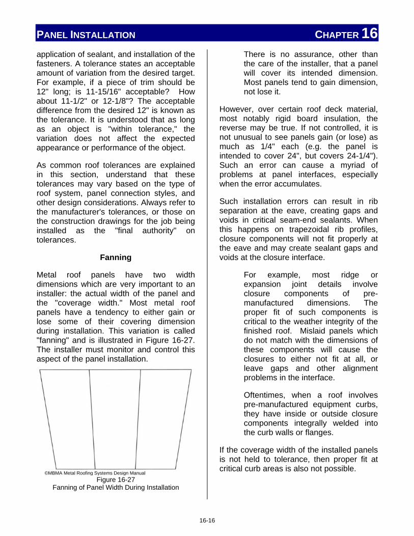
PANEL INSTALLATION CHAPTER 16 application of sealant, and installation of the fasteners. A tolerance states an acceptable amount of variation from the desired target. For example, if a piece of trim should be 12" long; is 11-15/16" acceptable? How about 11-1/2" or 12-1/8"? The acceptable difference from the desired 12" is known as the tolerance. It is understood that as long as an object is "within tolerance," the variation does not affect the expected appearance or performance of the object.
As common roof tolerances are explained in this section, understand that these tolerances may vary based on the type of roof system, panel connection styles, and other design considerations. Always refer to the manufacturer's tolerances, or those on the construction drawings for the job being installed as the "final authority" on tolerances.
Fanning
Metal roof panels have two width dimensions which are very important to an installer: the actual width of the panel and the "coverage width." Most metal roof panels have a tendency to either gain or lose some of their covering dimension during installation. This variation is called "fanning" and is illustrated in Figure 16-27. The installer must monitor and control this aspect of the panel installation.
Figure 16-27
Fanning of Panel Width During Installation
There is no assurance, other than the care of the installer, that a panel will cover its intended dimension. Most panels tend to gain dimension, not lose it.
However, over certain roof deck material, most notably rigid board insulation, the reverse may be true. If not controlled, it is not unusual to see panels gain (or lose) as much as 1/4" each (e.g. the panel is intended to cover 24", but covers 24-1/4"). Such an error can cause a myriad of problems at panel interfaces, especially when the error accumulates.
Such installation errors can result in rib separation at the eave, creating gaps and voids in critical seam-end sealants. When this happens on trapezoidal rib profiles, closure components will not fit properly at the eave and may create sealant gaps and voids at the closure interface.
For example, most ridge or expansion joint details involve closure components of pre-manufactured dimensions. The proper fit of such components is critical to the weather integrity of the finished roof. Mislaid panels which do not match with the dimensions of these components will cause the closures to either not fit at all, or leave gaps and other alignment problems in the interface.
Oftentimes, when a roof involves pre-manufactured equipment curbs, they have inside or outside closure components integrally welded into the curb walls or flanges.
If the coverage width of the installed panels is not held to tolerance, then proper fit at critical curb areas is also not possible.
©MBMA Metal Roofing Systems Design Manual
16-16

PANEL INSTALLATION CHAPTER 16 Finally, off-module installation will usually result in seam alignment problems, since the error in installation module is rarely consistent at both the upslope and down-slope ends of the panel(s), as well as interfaces at walls and other terminations.
It is vital and incumbent upon the installer to maintain the proper panel dimension when installed, and there is help available to prevent fanning during installation. Many manufacturers offer "spacer" tools, or "module makers" as they are sometimes called, to help control the coverage dimension during installation. An example of such a tool is shown in Figure 16-28.
Figure 16-28
Spacer Tools Help Hold Panel Module
Such tools can also be fashioned by the contractor from simple and readily available materials. The best such tools are adjustable so that the installer can intentionally "stretch" or "shrink" a panel at will. This facilitates a recovery from installation error, should one occur.
Acceptable Tolerances
As mentioned earlier, some installation tolerances are product or system specific, and must be provided by the individual product manufacturer. Such data will
supersede the tolerances within this section.
The following information is sufficient for general reference purposes, and where the manufacturer's proprietary practices and instructions do not conflict.
Most vertical rib panel profiles will tolerate an installed coverage width error of +1/16" (from true) individually without difficulty. ("A" in Figure 16-29)
Most trapezoidal panels will tolerate an installed coverage width error of +3/32". ("A" in Figure 16-29)
Trapezoidal standing seam panels are particularly susceptible to spreading or shrinking depending on where the worker is standing when putting down the clips. If the upslope worker is standing on the panel and the eave worker is not, then the panel may spread more at one end than at the other end causing accumulating problems. Spacer tools are critical when installing this type of panel.
Accumulated error in panel coverage for either profile, however, should not exceed +1:500. In the case of fanning, (Figure 16-29, left and center) the total deviation from true between the plus and minus dimensions should not exceed 1/500 of L (L=Length). That is to say that combined errors A and B (Refer to Figure 16-29, center) when added together should not total more than 1/500 of L (L=Length).
In the case of dog-legs, all combined errors A, B, and C when added should not total more than 1/500 of L (L=Length). (Refer to Figure 16-29, right)
16-17

PANEL INSTALLATION CHAPTER 16 While any error within these tolerances is generally not cause for rejection, there may be exceptions:
• If for some reason the error compromises weather integrity, or threatens to do so, it may be deemed unacceptable.
• If the error interferes with some critical roof layout detail, such as the exact placement of an expansion joint, or critical location of mechanical equipment, roof penetration, or similar scenario, it may be deemed unacceptable.
If the roof is steep-sloped, or is used in a highly visible, architectural presentation, then other tolerance restrictions may be given. Further consideration is given in Section 16.4.3.2, Aesthetics of Alignment.
Figure 16-29
Reference for Allowable Tolerances
16.5 Field Operations
Not all roof installation work is done on the roof surface itself. One operation often performed on the ground at the job site is the brake forming of certain panels, related trim, and other roof components. The brake, as show in Figure 16-30, is detailed in Section 12.8, Brake.
Figure 16-30
On-Site Brake Forming of Roof Material
16.5.1 Field Cutting of Panels and Trim
Every installation will require some trimming and cutting of panel and trim pieces. Failure to properly cut metal roof materials can jeopardize both the appearance and performance of a roof system.
A few rules when field cutting sheet metal should be followed. First, abrasive or other blades which heat the metal and create heavy burrs should be avoided. This is particularly true when cutting coated steel. Such cutting operations exceed the melting temperature of the metallic coating, and melt it away from the cut edge, causing a corrosion site. The effects of abrasively cutting panels, premature corrosion, and rusting, can be seen in Figure 16-31.
Figure 16-31
Premature Corrosion and Rust Due to Abrasive Cutting of the Panel
© Rob Haddock, all rights reserved
16-18

PANEL INSTALLATION CHAPTER 16 When cutting panels, a lot of steel bits, commonly referred to as swarf, gets scattered and thrown onto adjacent surfaces. If not thoroughly and promptly cleaned up and removed, this swarf will cause potential corrosion or heavy staining as shown in Figure 16-32.
Electric circular saws have typically been eliminated from use. Currently, new circular saw blade products have emerged on the markets which claim no damage to metallic coatings. If in fact such claims are validated, these special saw blades may be deemed acceptable to use, but the installer should remain suspect.
Figure 16-32
Failure to Remove Cutting Debris (Swarf) Quickly Causes Panel Corrosion and Rust
Approved methods of cutting include aviation snips, sheet metal hand shears, electric sheet metal shears, and pneumatic or electric nibblers. Most of these tools will be discussed in more detail in Chapter 12,
Tools and Field Operations. Properly using these tools will deliver the cleanest cuts, cause the least damage, and leave a minimal burr.
Plan the installation
When possible, locate the field cut away from the weather. For instance, if a roof panel has to be trimmed to length, trim the top of the panel, where the cut will be hidden from the weather with a ridge flashing. This is shown in Figure 16-33. When it is necessary to cut an eave flashing to length, put the field cut end beneath the factory cut end of the adjacent section.
Figure 16-33 Properly Cut Panel End Protected by Ridge Cap
In some cases, the cutting tools described above will not be adequate or practical. An example of this happens after panels are installed and it becomes necessary to cut through multiple layers of sheet metal in the area of a folded seam. In such instances, a hack saw or reciprocating saw is preferred.
However, an abrasive saw or plasma-arc may be used in such an area under the following carefully controlled circumstances:
1. The nature of the cut must be such that it will be permanently protected from the weather (for instance beneath a curb flange)
2. Adjacent materials and surfaces must be protected from hot sparks and shrapnel (swarf) during the cutting procedure.
16-19

PANEL INSTALLATION CHAPTER 16 16.5.2 Brake Forming
Sometimes, it is necessary to bend metal panel, trim, and flashing material on the job using equipment such as a portable brake. Here's how to do this task: • Mark and set the metal squarely into the
jaws of the brake. • Clamp the jaws down using the jaw-lock
handle. • Pull the folding handle using even
pressure until the metal is at the desired angle.
• Release the jaw-lock handle and carefully remove the formed piece.
While not difficult, brake operation does require practice and attention to details. New employees, and those unfamiliar with the brake, should receive proper training before attempting to form materials. Using scrap as practice material provides a cost effective and convenient practice opportunity.
Similar forming tools such as hand-folding brakes and tongs are used in a similar way.
Summary
Panel installation is arguably the most noticeable activity in the roof installation process. It is also a key activity, and correct panel installation is essential to the proper look, performance, and long life of any roof.
It does require the use of tools and other on-site activities that will affect this activity. In order to correctly install any panel, an installer must also be familiar with the material in the following chapters:
• Chapter 9, Safety Issues • Chapter 11, Delivery, Receipt,
Storage, and Handling of Materials • Chapter 12, Tools and Field
Operations
• Chapter 13, Sealants • Chapter 14, Fasteners • Chapter 15, Seam Joining
Notes: ______________________________________________________________________________________________________________________________________________________________________________________________________________________________________________________________________________________________________________________________________________________________________________________________________________________________________________________________________________________________________________________________________________________________________________________________________________________________________________________________________________________________________________________________________________________________________________________________________________________________________________________________________________________________________________________________________________________________________________________________________________________________________________________________________________________________________________________________________________________________________________________________________________________________________________________________________________________________________________________________________________________________________________________________________________________________________________________________________________________________________________________________
16-20

PANEL INSTALLATION CHAPTER 16 ______________________________________________________________________________________________________________________________________________________________________________________________________________________________________________________________________________________________________________________________________________________________________________________________________________________________________________________________________________________________________________________________________________________________________________________________________________________________________________________
16-21

Chapter 17: Maintenance Chapter Contents
17. Introduction ...................................................................................................... 17-1
17.1 Siding .................................................................................................... 17-1
17.2 Mortar .................................................................................................... 17-1
17.3 During Construction – Daily QC .................................................. 17-2
17.3.1 Protecting Roof Coating During Installation ....................... 17-2
17.3.2 Remove Strippable Film and Protective Coatings if Applicable ........................................................... 17-2
17.3.3 Keeping Roof Clear Of Debris .............................................. 17-2
17.3.4 Foot Traffic ............................................................................. 17-3
17.3.5 Touch-Up Paint (During Installation) ................................... 17-3
17.3.6 Photos of Work In Progress .................................................. 17-4
17.3.7 Daily Work Completed Checklist .......................................... 17-5
17.4 After Installation Is Complete ....................................................... 17-6
17.4.1 Clean-Up ................................................................................. 17-6
17.4.2 Walking Roof To Create Punch List ..................................... 17-6
17.4.3 Touch-Up Paint (After Installation) ....................................... 17-6

MAINTENANCE CHAPTER 17
17. INTRODUCTION By definition, maintenance is the care and up-keep of an item or property. Maintenance for a metal roof installation includes activities and materials the installer uses which are not directly involved in the installation of the roof system, but rather whose purpose is to protect and maintain the appearance and performance of the roof system as originally designed.
Roof maintenance actually begins during construction. The material covered in this chapter is intended to be used during a new or re-roof application of a metal roof system. It is not intended as a guide for a yearly, 5-year or similarly long-term maintenance program. The manufacturer of the roof system being installed should be contacted if such long-term maintenance information is desired.
17.1 Siding
An installer must interface with the structure siding during a roof installation, but attention should also be given to the siding at other times as well. During a roof installation, the sides of the structure can be dirtied, marred, or damaged. The installer should inspect, evaluate, clean, and correct any siding problems caused by the roof installation. This may occur as material is stored, formed, and transported from the ground to the roof early in the installation. It may also occur during a re-roof installation as old material is removed and transported away. While the roof installation is underway, or even during clean-up, the siding may also be affected. Eave, soffit, and rake work are often performed in close proximity to the side of the structure. This work may even involve the propping of ladders and other material against the siding while work is underway.
Figure 17-1
Carelessness During the Roof Installation Can Damage the Structure Siding
As material is dropped, it often slides off the roof surface, and the siding may be damaged, as seen in Figure 17-1. Spills and runoff prior to the installation of a gutter or drainage system may also adversely affect the siding, as shown in Figure 17-2. During clean-up, dirt and debris are often "swept off the roof" and find their way onto the siding. Care should be taken in removing leftover material, tools, and any equipment from the roof to avoid damaging the siding.
Figure 17-2 Spills and Runoff During Installation Often
Affect the Structure Siding
17.2 Mortar
As seen in Figure 17-3, whenever possible, masonry work should be completed and dry before the roof is installed, but sometimes this is not possible. Mortar from masonry walls may severely etch the coating of roof
17-1

MAINTENANCE CHAPTER 17 panels. Wet mortar and masonry is corrosive, while dried material is highly abrasive and can be tracked onto other portions of the roof causing further damage.
Figure 17-3 Masonry Should Be Completed and
Dry Before Roof Installation
Roof panels in areas where this work is being done should be protected. If mortar drops on the panels, like that in Figure 17-4, it should be cleaned off before it is allowed to dry.
Figure 17-4 Mortar Droppings Should Be Cleaned Immediately.
17.3 During Construction – Daily QC
Daily maintenance during roof construction involves activities which protect, clean, and correct errors on portions of the roof system on which work was performed that day. This daily maintenance also acts a "Daily Quality Control" (QC), as well as improving job site safety.
17.3.1 Protecting Roof Coating During Installation
Once installed, the panel coating is the portion of the roof most likely to become damaged. The majority of this protection involves covering the surface until the last moment. Protecting the roof coating will involve keeping any factory-applied protective film on the panel until work safely moves away from that panel, establishing common walkways, and laying non-slip protective covering where necessary, covering any roof area where work is being performed by other trades such as masons, and where welding or soldering is taking place.
This protection also includes sweeping, cleaning, and touch-up of any damage which may have occurred during the day.
17.3.2 Remove Strippable Film and Protective Coatings if Applicable
Some paint types are more fragile than others, and often painted steel and aluminum surfaces are protected with a strippable plastic film. This film is applied during coil processing, and intended to help protect the finish during transit and installation. It is critical that the installer strip this film prior to prolonged exposure to sunlight, as it will become brittle and very difficult to remove after such exposure.
17.3.3 Keeping Roof Clear of Debris
Roof and gutters should be kept free of debris. This is a safety as well as a maintenance issue. Dirt and debris left on the roof will create a slippery, unsafe walking surface; absorb moisture, creating increased corrosion and rust; and have the potential to clog and jam the drainage system creating standing water, flooding, and possible ice jams.
Check and follow jobsite rules for trash removal. Some jobs require the roofing team
17-2
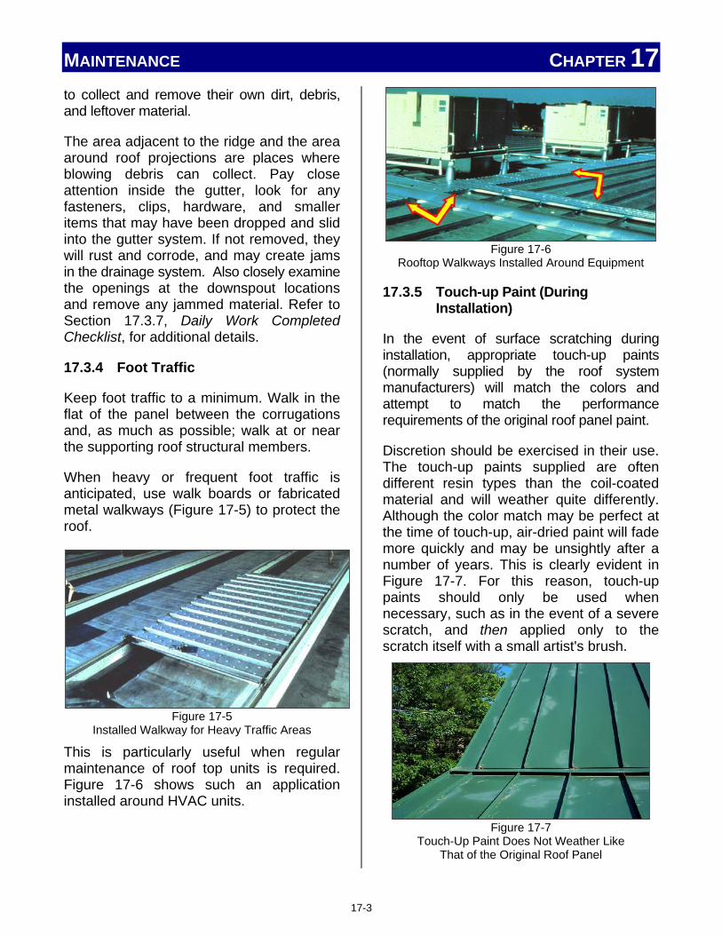
MAINTENANCE CHAPTER 17 to collect and remove their own dirt, debris, and leftover material.
The area adjacent to the ridge and the area around roof projections are places where blowing debris can collect. Pay close attention inside the gutter, look for any fasteners, clips, hardware, and smaller items that may have been dropped and slid into the gutter system. If not removed, they will rust and corrode, and may create jams in the drainage system. Also closely examine the openings at the downspout locations and remove any jammed material. Refer to Section 17.3.7, Daily Work Completed Checklist, for additional details.
17.3.4 Foot Traffic
Keep foot traffic to a minimum. Walk in the flat of the panel between the corrugations and, as much as possible; walk at or near the supporting roof structural members.
When heavy or frequent foot traffic is anticipated, use walk boards or fabricated metal walkways (Figure 17-5) to protect the roof.
Figure 17-5 Installed Walkway for Heavy Traffic Areas
This is particularly useful when regular maintenance of roof top units is required. Figure 17-6 shows such an application installed around HVAC units.
Figure 17-6 Rooftop Walkways Installed Around Equipment
17.3.5 Touch-up Paint (During Installation)
In the event of surface scratching during installation, appropriate touch-up paints (normally supplied by the roof system manufacturers) will match the colors and attempt to match the performance requirements of the original roof panel paint.
Discretion should be exercised in their use. The touch-up paints supplied are often different resin types than the coil-coated material and will weather quite differently. Although the color match may be perfect at the time of touch-up, air-dried paint will fade more quickly and may be unsightly after a number of years. This is clearly evident in Figure 17-7. For this reason, touch-up paints should only be used when necessary, such as in the event of a severe scratch, and then applied only to the scratch itself with a small artist's brush.
Figure 17-7 Touch-Up Paint Does Not Weather Like
That of the Original Roof Panel
17-3

MAINTENANCE CHAPTER 17 When touch-up paint is used by the installer, be sure to:
• Use only materials supplied and approved for use by the panel manufacturer.
• Follow all mixing and application instructions.
• Make sure the surface is clean and dry.
• Do not apply if the outside temperature is too hot or too cold.
If unsuitable touch-up paint is used, it may cause adhesion failures, differential chalking, and a faded appearance on the painted panel which may require the repainting of the entire affected surface, sometimes years after the initial installation was completed. The cost of such field painting can be substantial.
Remember that from an aesthetic standpoint, over-use of touch-up paint will be much more noticeable than the untouched scratch in several years' time. If surface scratching is indeed excessive and unacceptable, the material should be replaced rather than touch-up painted.
These same principles apply to the painting of other components in order to match pre-finished metal panels and flashings. Most touch-up paint applications will have very different weathering effects than the factory finishes, and can mismatch in a few years, even when the initial match is perfect. Whenever possible, use pre-finished sheet metal shrouds supplied by the roof system manufacturer to color-match other components and roof accessories, rather than air-dried paints. In the long run, this practice is often more economical.
17.3.6 Photos of Work in Progress
Today's technology has made documentation of work and job details amazingly easy and
necessary. A simple cell phone camera picture can document a pre-existing condition; work performed, but not visible at final installation; roof damage; and details of work completed. The ideas are numerous, but the following list of areas will help the installer understand where photographs can document, plan, and communicate important aspects of the job:
Prior to Start: • Job site conditions
• Areas to stage material and equipment
• Existing roof conditions
• Areas of concern
During Installation: • Daily progress
• Underlayment
• Hidden fastener details
• Touch-up
• Damage, spills, repairs
After Installation Completed: • Work performed / completed
• Existing roof penetrations
• Avoids conflict on work performed after initial installation
• Details not visible from ground level
• Clean-up
In addition to an actual visual record, every digital photo has a date and time stamp automatically recorded with it, while some systems are able to store additional information with each picture. When these photos are attached to daily logs, inspection records, and other job documentation; a powerful and valuable record of the installation is formed which can serve many purposes.
17-4

MAINTENANCE CHAPTER 17 17.3.7 Daily Work Completed Checklist A valuable and effective tool for an installer is a daily checklist of the work and maintenance activities completed that day. When completed, signed, dated, and filed on a daily basis, the installer will have a documented record of the installation, along with any deviations, communications, issues, and corrections noted as they occurred during the job.
17.3.7.1 Touch-up Paint (During Installation)
Refer to Section 17.3.5, Touch-up Paint During Installation, for touch-up details. The checklist should include any touch-up paint applied that day, who applied it, and where (within a reasonable amount of detail) the touch-up is located.
17.3.7.2 Clean-up Metal Filings
The checklist should include the person responsible for clean-up of debris (Section 17.3.3, Keeping Roof Clear of Debris), especially any metal filings, chips, and shavings. This is one activity which should be done on a daily basis due to the rapid formation of rust, staining, and corrosion. Rain, humidity, dew, and condensation all provide enough moisture to enable the small metal pieces to rust and begin to corrode. This can result in panel damage as shown in Figure 17-8.
17.3.7.3 Remove Dust and Debris Section 17.3.3, Keeping Roof Clear of Debris, discusses details of roof clean-up. The checklist should include the names of those responsible. Make sure those performing this task are aware of jobsite rules for trash removal and locations for placing trash.
Figure 17-8 Panel Damage Resulting From Metal Filings
Left On the Roof Surface
17.3.7.4 Remove Masking on Installed Panels and Trim
Details of this activity are documented in Section 17.3.2, Remove Strippable Film and Protective Coatings if Applicable. Adding this step to the daily checklist ensures that the protective covering does not remain on the roof panel any longer than necessary, reminds the installer to perform this important task, and documents that it has been done.
17.3.7.5 Clear Valleys and Gutters
The roof areas most susceptible to collecting dirt and debris are valleys, gutters, and locations like those shown in Figure 17-9. Details of the cleaning of these areas are provided in Section 17.3.3 Keeping Roof Clear of Debris. Documenting and performing this on a daily basis during the installation avoids a build-up of dirt and debris. This type of material is easier to remove when dry and the amount of material is small. If allowed to get wet, it may dry, solidify, and become very difficult to remove.
17-5

MAINTENANCE CHAPTER 17
Figure 17-9 Roof Areas Like These Attract Dirt and Debris
If disagreements arise after the installation, which result in litigation, this daily checklist will be invaluable. Each log should be signed and dated, along with any comments, special issues, and notifications, which occurred during the day. It will also be helpful with larger crews to identify who performed some of the various activities, such as installed flashing or touched-up panels during the installation.
17.4 After Installation Is Complete
For the installer of the roof, there are still a few maintenance items to be performed as the installation wraps-up and is completed. These maintenance items are very important and serve as a final check, inspection, and evaluation of the roof before "signing off the job." Refer to Chapter 19, Installer Checklists, for supplemental information.
These "post-installation" maintenance items include a final cleaning of the roof, development of a final "punch-list" of small items which need corrected, and any necessary paint touch-up the roof structure may require.
17.4.1 Clean-Up
This final clean-up should take place after all leftover material, tools, and equipment, have been taken off the roof. Sometimes
this clean-up is quickly accomplished by including additional available roofing members, starting on the far side of the roof, and proceeding to the ladder, or egress point, of the roof. Moving in this direction eliminates walking over a previously cleaned surface, and presents the cleanest roof surface once the roof is vacated.
17.4.2 Walking Roof to Create Punch List
Prior to the final roof clean-up, and when the installation is "completed," one or two experienced roofing team members should "walk the roof," covering every portion of the roof, carefully looking for items which need further attention and/or correction. This may include improperly secured fasteners, removal of excess sealant, alignment and adjustment of trim and /or panels, and any items that "don't look right."
These areas should be marked in a way that is easily spotted, yet can be cleaned or removed after the correction is made. Masking or painter's tape has been found to be useful for such marking. In addition to marking the item on the roof, a written list is developed and each item is crossed off as it is corrected.
17.4.3 Touch-up Paint (After Installation)
Details of touch-up painting are found in Section 17.3.5. If done properly, this "final" touch-up should be minimal. As final clean-up takes place, and material, equipment, and protective coverings removed, there may be areas requiring touch-up. This final touch-up should be performed using the proper material, following all instructions as given with the touch-up material.
Any touch-up should be documented, as previously done using the daily checklist.
17-6

MAINTENANCE CHAPTER 17 Summary
Maintenance of a metal roof system begins during its construction and installation. By following the procedures and performing the activities discussed in this chapter, the installer lays a solid foundation for a long lasting metal roof, and is able to hand-off to the customer a roof system which will provide years of quality performance.
Notes: ____________________________________________________________________________________________________________________________________________________________________________________________________________________________________________________________________________________________________________________________________________________________________________________________________________________________________________________________________________________________________________________________________________________________________________________________________________________________________________________________________________________________________________________________________________________________________________________________________________________________________________________________________________________________________________________________________________________________________________________________________________________________________________________________________________________________________________________________________________________________________________________________________________________________________________________________________________________________________________
________________________________________________________________________________________________________________________________________________________________________________________________________________________________________________________________________________________________________________________________________________________________________________________________________________________________________________________________________________________________________________________________________________________________________________________________________________________________________________________________________________________________________________________________________________________________________________________________________________________________________________________________________________________________________________________________________________________________________________________________________________________________________________________________________________________________________________________________________________________________________________________________________________________________________________________________________________________________________________________________________________________________________________________________________________________________________________________________________________________________________________________________________________________________________________________________________________________________________________________________________________________________________________________________________________
17-7

Chapter 18: Codes/Standards and Specifications Chapter Contents
18. Introduction ...................................................................................................... 18-1
18.1 Overview .............................................................................................. 18-1
18.1.1 Specifications ........................................................................ 18-1
18.1.2 Standards ............................................................................... 18-1
18.1.3 Codes ...................................................................................... 18-1
18.1.4 Becoming Law ....................................................................... 18-2
18.2 Building Codes .................................................................................. 18-2
18.2.1 National .................................................................................. 18-2
18.2.2 Local ....................................................................................... 18-3
18.3 Energy Codes ..................................................................................... 18-3
18.3.1 National .................................................................................. 18-3
18.3.2 Local ....................................................................................... 18-3
18.4 Home Rule Doctrine ......................................................................... 18-3
18.5 Guarantees and Warranties .......................................................... 18-4
18.5.1 Weather-tight Warranty Text ................................................. 18-4
18.5.2 When Conflicts Arise ............................................................. 18-5

CODES / STANDARDS AND SPECIFICATIONS CHAPTER 18
18. INTRODUCTION Along with the large variety of panel profiles, seam types, and roof design configurations, there are other factors which will change how a metal roof system must be installed. Applicable codes, standards, and specifications developed and approved by interest groups, regulators, and legislators must be followed by the installer.
Failure to follow these accepted procedures and methods can result in lawsuits, inspection failures, and added project costs. Most codes, standards, and specifications are designed to ensure quality and safety in the construction, and specific requirements in energy efficiency.
Important Note
Different codes, standards and specifications may apply to similar jobs, even within the same geographic vicinity or similar structure type. For example,
• Occupancy considerations: facilities such as hospitals and fire houses typically require higher standards than other buildings, such as agricultural buildings.
• Roof pitch and geometry: these design issues directly affect wind impact on a roof.
• Other factors: local topography, wall openings, and parapets are also taken into account since they, too, affect wind load on a roofing system.
Always check and clarify before starting any installation.
18.1 Overview
Historically, geographically-based roofing codes have been developed in response to specific local, regional, or national concerns. The net result has been a complex mix of regulations that make it difficult to keep up-to-date on all the requirements that could possibly impact new construction and renovation projects.
It is virtually impossible to develop one single set of criteria or standards to govern the manufacture, selection, installation, and maintenance of a metal roof system. Installers, however, must still comply with the code that relate to their work. Overlap in requirements can be confusing without a basic understanding of their development and enforceability.
Local government jurisdictions regulate the construction industry by means of building codes that are developed through an arduous process. This process is illustrated in Figure 18-1, and explained as follows:
18.1.1 Specifications
First, specifications are developed to clearly describe technical requirements for materials, procedures, and services. Specifications may state the requirements for a desired product and the process used to produce it.
18.1.2 Standards
Standards are guidelines, or principles, that are agreed upon by a broad spectrum of the industry, typically working through a trade association. The association may be at a state, national, or international level.
18.1.3 Codes
When standards or requirements are published, they may become codes. By publishing these standards, they become available not only to members of the
18-1

CODES / STANDARDS AND SPECIFICATIONS CHAPTER 18 developing organizations, but to any interested party.
18.1.4 Becoming Law
Once a code is adopted by a jurisdiction, it becomes law. The construction industry is governed by a collection of regulations and requirements. By becoming law, these rules and regulations are designed to provide uniformity on minimum design and construction practices, thereby avoiding inconsistencies arising from differing approaches of architects, builders, and installers. When jurisdictions adopt these national, state, or local codes, they are no longer recommendations, but the law, and they must be followed.
Figure 18-1 How Specifications, Standards, and
Codes Are Related
18.2 Building Codes
Building codes normally set roof requirements affecting the strength and safety of the roof system. These requirements translate into installation
requirements such as type, quantity, and spacing of fasteners, underlayment and related fastening requirements, and gutter and drainage details. A metal roof presents a unique situation.
Metal roof systems depend on attachment to the building structures with clips which are spaced throughout the field of the roof. This type of installation is strikingly distinct from alternative roofing systems (like asphalt or built-up roofs) that are uniformly attached across the entire field of their surface with continuous adhesives, fasteners, or weight (ballast). In addition, standing seam metal roof systems have vertical seam components that protrude from the field of the roof. This creates an uneven surface and a non-uniform stiffening of the panel against the forces of wind.
If a roof installation is located in a designated historic district, or on an historic structure, additional requirements may apply which will likely affect the style and type of roof structure and even allowable materials.
18.2.1 National
In the past, there were three building codes. Unfortunately, they were regional models, and written by three separate organizations of building officials. Each state, county, and municipal jurisdiction typically adopted one of these regional codes. They were known as the Uniform Building Code (UBC) published by ICBO1, the BOCA2 National Building Code, and the SBCCI3 Standard Building Code.
In 1994, the three model code organizations (ICBO, BOCA, and SBCCI) were consolidated
1 ICBO – International Council of Building Officials 2 Building Officials and Code Administrators International 3 Southern Building Code Congress International
18-2

CODES / STANDARDS AND SPECIFICATIONS CHAPTER 18 into one organization – the International Code Council (ICC).
The code developed by the ICC to address commercial construction is the International Building Code (IBC). In 2000, the first comprehensive and coordinated set of the IBC was published. An updated edition of the code is published every three years. This code and its revisions do not become law until adopted by the local jurisdiction.
18.2.2 Local
Local building codes which may apply to a metal roof installation are too numerous to list, vary greatly, and change frequently.
It is best to check with the administration offices of the local jurisdiction. Many have knowledgeable code officials and inspectors who are quite capable of answering related questions.
18.3 Energy Codes
About one-third of all energy in the United States is consumed in buildings. While building codes deal with the structural aspects of the installation, energy codes deal with the energy-conserving aspects of the roof system. Such requirements may affect fastening and sealing, coatings, touch-up, insulation, and related installation factors. Energy efficiency, as it relates to a metal roof installation, is examined in more detail in Section 10.3, Energy Efficiency.
18.3.1 National
Nationally, this high level of energy usage led to the development of various energy standards and codes with support from the U.S. Department of Energy (DOE). Many states, such as California and Oregon, publish their own energy codes. Other states rely heavily on the Model Energy Codes or the International Energy Conservation Code.
18.3.2 Local
Local energy codes may apply to a metal roof installation. Local energy codes are not as common as building codes, but are already in place in many larger cities and some states, like California. Be aware that many municipalities merely adopt the codes already established at the state or national level.
Again, it is best to check with the administration offices of the local jurisdiction. Many have code officials, and inspectors who are energy conscious and capable of answering related questions.
18.4 Home Rule Doctrine
Because of the large number of specifications, codes, and standards that affect the construction and metal roof industry, conflicts between their requirements will inevitably arise. When such a conflict occurs, the installer may need to apply the concept of "Home Rule Doctrine," which means, "The most stringent requirement applies." Our governmental structure allows the lowest governing body to have final control, as long as their requirement is equal to or more stringent than, the state or federal requirement.
Home Rule Doctrine Example
Here is an example of "Home Rule Doctrine" as it might apply to a roof's ability to withstand wind uplift. For the installer, meeting wind uplift requirements normally translates into requiring installation of a certain number of fasteners per roof panel with a specified distance between the fasteners. The current IBC may allow a minimum of 9 fasteners per panel. A state code may require 12 fasteners per panel. The county code may also equate to 12, but the local code may be higher, specifying an uplift resistance which equates to 15 fasteners in each panel. In this case, the 15 fasteners per panel would be enforced because it is the most stringent. Keep in mind
18-3

CODES / STANDARDS AND SPECIFICATIONS CHAPTER 18 that any Property Owners' Association's CC&Rs (Covenants, Conditions and Restrictions) could require a wind uplift resistance which would require even more fasteners per panel.
18.5 Guarantees and Warranties
While these are not laws, both guarantees and warranties are legally binding documents. Even though, for our purposes, they are very similar, there are legal differences, but both are assurances that certain characteristics or conditions will be maintained for a designated period of time. In addition to an expected condition, like not leaking, other roof characteristics are often guaranteed. Color retention, energy efficiency, and longevity of a roof are often stated to maintain a level of performance for many years. A well-known selling point for a metal roof system is its longevity.
Unfortunately, these promises are based on certain factors, many which take place during the installation and are the responsibility of the installer. The use and spacing of designated fasteners, sealant, environmental conditions, and failure to maintain tolerances during installations may all void any warranty or guarantee issued by a manufacturer.
A preferred method and "Best Practice" is to take digital photographs or video of critical components, installation factors, or portions of an installation which will not be visible after the installation is complete. This action documents, for all parties involved, certain details, conditions, and factors of the installation in the event there are questions, concerns, or even litigation.
18.5.1 Weathertight Warranty Text
Obviously a roof must be weathertight and not leak, but how is this determined and how does this affect the installer?
Many factors like weathertightness, water resistance, and leaking are performance expectations, but are not directly covered in any code. They are, however, usually covered in an installation, or manufacturers, warranty or guarantee. The expected level of performance is usually determined as follows:
• All exterior gutters and downspouts shall be designed for rainfall intensity based upon a 5-year recurrence interval for a 5-minute duration.
• All interior gutters, valleys, and downspouts shall be designed for rainfall intensity based upon a 25-year recurrence interval based on a 5-minute duration.
No matter what a manufacturer says in a warranty or guarantee, the following clause, or something similar, is often included;
"XYZ4 Company, Inc. assumes no responsibility for any problems which might arise as a result of improper installation or any personal injury or property damage that might occur with the products use."
In order to meet and exceed the expected, and guaranteed, levels of performance, an installer, must be sure to use the correct materials and follow the established procedures. Unfortunately, most leak issues are caused by improper installation and not the failure of a manufactured panel, fastener, or sealant.
4 Not a real Company
18-4

CODES / STANDARDS AND SPECIFICATIONS CHAPTER 18
Installer Note Installers should be aware that they have much more to do with a roof system being weathertight than any other party involved with the project. As a result, installers are usually the first party contacted when leaks occur. A typical contract will normally require some minimum time that an installer will be responsible for the weathertightness of an installation. Even if a manufacturer gives a weathertightness warranty, be aware that most of these warranties require the installer to be responsible for an initial period of weathertightness. If there is a manufacturer’s weathertightness warranty required on the project, the installer should check with the manufacturer before installation begins to insure that all requirements necessary to insure the warranty are understood. The installer must then make sure and verify that all requirements have been completed before the installation is considered completed.
Installer Warranty Precautions
There are several precautions an installer should follow to minimize liability, confusion, and misunderstanding concerning contracts and manufacturer warranties.
• Always follow any manufacturer or job specific engineering details during the installation. These are designed to provide maximum weathertightness, performance and protection. If there are questions or concerns, they should be resolved and documented before proceeding.
• Be aware of and involved in any additional roof work which is to be completed or added by other trades, or workers; especially if roof penetrations are involved. This should include documentation of any communication with the others involved with the additional work, follow-up checks, photographs, and verifications.
• Any additional documentation relating to the above two issues should be filed and available for an appropriate period of time. Keep in mind that many warranties may be significant in length.
18.5.2 When Conflicts Arise
There will be cases when conflicts arise between the installer and the approving authority. An installer may be told to install a product in a certain manner, which is in direct conflict with the manufacturer's instructions, job calculations, and/or the principles outlined in this manual. When this situation occurs, immediately contact the responsible party about the situation. The responsible party shall handle and resolve any disputes, and get a written waiver of responsibility if the work is to proceed as instructed by the approving authority.
Full documentation of the situation, including the conflicting instructions, specific details, photographs, and the actions taken by the installer must be done in writing as a matter of permanent record. Installers and their management are encouraged to maintain these records for a period of not less than 10 years.
Summary
When the installer fails to use the proper materials and methods, whether or not it is intentional, they are in danger of breaking the law and possibly voiding the roof warranty. These are costly mistakes, and often wind up in litigation, which may go on
18-5

CODES / STANDARDS AND SPECIFICATIONS CHAPTER 18 for years. In addition, it may be years after the initial roof installation before certain infractions are discovered and litigation begins.
Such installation mistakes may be avoided by following two basic guidelines. First, prior to beginning the job, find out and understand the codes, standards, and specifications which are applicable to the work being performed.
Secondly, during the installation, if conflicts, confusion, or uncertainty arise, immediately contact the responsible party about the situation. When resolved, be sure to document the details of the resolution of the matter.
Notes: ____________________________________________________________________________________________________________________________________________________________________________________________________________________________________________________________________________________________________________________________________________________________________________________________________________________________________________________________________________________________________________________________________________________________________________________________________________________________________________________________________________________________________________________________________________________________________________________________________________________________________________________________________________________________________________________________________________________________________________________________________________________
________________________________________________________________________________________________________________________________________________________________________________________________________________________________________________________________________________________________________________________________________________________________________________________________________________________________________________________________________________________________________________________________________________________________________________________________________________________________________________________________________________________________________________________________________________________________________________________________________________________________________________________________________________________________________________________________________________________________________________________________________________________________________________________________________________________________________________________________________________________________________________________________________________________________________________________________________________________________________________________________________________________________________________________________________________________________________________________________________________________________________________________________________________________________________________________________________________________________________________________________________________________________________________________________________________
18-6

Chapter 19: Installer Checklists Chapter Contents
19. Introduction .................................................................................................... 19-1
19.1 Pre-installation Checklists ............................................................ 19-1
19.2 Checklists During Installation ..................................................... 19-2
19.3 Post-Installation / Inspection / Maintenance Checklists ...... 19-2
19.4 Inspection Procedures ................................................................... 19-5
19.4.1 Building Interior .................................................................. 19-5
19.4.2 Gutters ................................................................................. 19-5
19.4.3 Downspouts ........................................................................ 19-6
19.4.4 Edge and Rake Metal .......................................................... 19-6
19.4.5 Hips and Ridges .................................................................. 19-7
19.4.6 Valleys .................................................................................. 19-7
19.4.7 Roof-to-Wall Flashings ....................................................... 19-8
19.4.8 Penetrations ........................................................................ 19-8
19.4.9 Metal Panels and Seams .................................................... 19-9

INSTALLER CHECKLISTS CHAPTER 19
19. INTRODUCTION Checklists are invaluable tools for the Installer to use at any stage of a roof installation. By definition, a checklist is merely a list of items for comparison. Checklists may be created by anyone interested in documenting some aspect of the roof installation. (Figure 19-1)
Figure 19-1 Checklists Are a Valuable Tool During
Any Stage of a Roof Installation
Roofing checklists may include installer activities such as receipt and inventory of materials, progress and completion of tasks, or inspection and evaluation of a roof (new or old). Checklists help the installer to: Ensure the right materials, supplies,
and tools are available and in the right quantity before attempting to perform a task.
Schedule work which needs to be performed, and avoid delays by shifting or re-adjusting the installation based on the checklist information.
Document key information; the "who, what, when, and where" of the job.
Provide legal documentation (especially when signed, dated, and kept on file) of important information in the event of litigation.
Installer Note
Installers are free to develop their own checklists for any aspect of a job where they feel it will be a benefit. Such lists may be items to bring to the job site from the home office, documents to sign and verify at the end of the day, or items to bring "roof top" from the truck or ground level. Remember, when it gets written down, it gets harder to forget.
19.1 Pre-installation Checklists
An installation progresses much smoother when all the necessary tools, materials, and equipment are available in the right quantity and in the right location. Documents used during the job estimation and order processes are types of checklists, and usually evolve into what is commonly called the Bill of Materials, or BOM. This BOM is used to check the material, supplies, or special tools (those required to be bought, rented, or leased) required for the job. Be aware that the BOM may have part numbers unique to the distributor or manufacturer which make it difficult to identify some components. Often, the manufacturer provides checklists as shown in Figure 19-2 of tools, materials, and products necessary for the installation. This information, along with packing slips, installation instructions, and other important documentation is often shipped along with the material. The specific box containing this documentation is individually marked on the outside of the package.
19-1

INSTALLER CHECKLISTS CHAPTER 19
Figure 19-2 Example of Manufacturer Tool, Equipment,
and Product Checklists
19.2 Checklists During Installation
Checklists used during the installation most often check and track activities, progress, and communication items. Each log should include the date and names or initials of key people. This includes not only the person completing the checklist, but also the person(s) performing specific tasks, such as sealing, gutter cleaning, or other trades performing work on the roof. Examples of detailed items a daily checklist may include are:
� Install underlayment
� Squares installed = _______
� Remove protective film from installed panels
� Check and clean gutters
� Notify electrician
� Notify/schedule HVAC reconnect
� Cover and secure stage material
� Store ladders and lock gate
� Photos
� Clean-up When such checklists are completed on a regular, or even a daily basis, then filed, a comprehensive record of the installation is created without any additional effort.
A useful, but often overlooked, item to include on a daily log is the addition of a section for random notes of significance. Such notes would include key factors like weather and jobsite conditions, delays, or injuries, of any nature.
19.3 Post-installation / Inspection / Maintenance Checklists
Checklists do not stop when the installation is completed. A checklist at this stage of the roof installation will help ensure that for new installations:
19-2

INSTALLER CHECKLISTS CHAPTER 19 The new roof is in its best condition for
the customer and sign-off on the job. The jobsite is left in an acceptable
manner; clean, neat, and secured. There are no tools, equipment, or
material left on the roof, or at the jobsite.
On maintenance or re-roof installations:
Documentation of changes, damage, or modifications since the initial installation or last inspection.
Areas requiring cleaning. Areas requiring touch-up or resealing,
such as terminations and masonry interfaces.
A checklist designed for the inspection or maintenance of a roof which has already been installed and in service for a period of time will have sections containing historical information to help the installer evaluate the current roof situation. As shown in the following examples, this type of checklist will include sections documenting:
General roof information (Figure 19-3)
Roof specification information (Figure 19-4)
A roof plan grid (Figure 19-5)
Building owner maintenance inspection checklist (completed by owner or owner maintenance members) (Figure 19-6)
Inspection Checklist (completed by roofing professional) (Figure 19-7)
Figure 19-3
General Roof Information on a Roof Maintenance Checklist
19-3

INSTALLER CHECKLISTS CHAPTER 19
Figure 19-4 Roof Specification Information on a Roof
Maintenance Checklist
Figure 19-5
Roof Plan Grid on Checklist
Figure 19-6 Owner Maintenance Inspection Checklist
Figure 19-7
Inspection Checklist (General)
19-4

INSTALLER CHECKLISTS CHAPTER 19 Such checklists provide the installer with additional income opportunities, and allow preventative, scheduled maintenance rather than costly, emergency repairs. When such a checklist does reveal a need for work to be done, it also becomes the basis for developing a list of materials and the information necessary to develop a job quotation for the customer.
19.4 Inspection Procedures
Each inspection should follow a prescribed routine that enables the person performing the inspection to examine each visible component of a roof system and identify areas requiring attention.
The following procedures can be used for both new and re-roof installations. However, some items may not be as applicable to some roof designs, or certain jobs.
Note
The following photos show examples an installer may typically find during an inspection. Some photos show areas that are in need of repair or correction, while others show areas that do not require additional attention.
19.4.1 Building Interior (Figure 19-8)
The starting point of any roof inspection should be on the ground, actually inside the building. A thorough inspection should check the interior for leaks and signs of water and staining. This includes:
� Interior walls
� Ceilings
� Insulation
Figure 19-8 Roof Inspections Should Begin Inside the Building
If any suspicious areas are found, a floor plan and/or roof plan (Figure 19-5) should be developed from this interior inspection, and indicate where there may be problems at the roof level.
After inspecting the interior, the exterior walls and overhangs should be inspected for moisture, cracks, and signs of movement.
19.4.2 Gutters (Figure 19-9)
Figure 19-9 Gutters Need Cleaned and Inspected Regularly
Gutters, whether they are hung at the eaves or hidden, should provide positive drainage. This is one component that should be inspected most rigorously, and several times, during the installation. Look for the following:
� Loose or missing fasteners
� Displaced or loose joints in the metal
19-5

INSTALLER CHECKLISTS CHAPTER 19
� Corrosion of metal components
� Debris and vegetation growth
� Attachment at eaves, broken or loose gutter straps, and brackets
� Sealants or solder displaying signs of cracking, weathering or aging at all joints and connections
� A secondary drainage system that is operational (e.g., front edge overflow)
19.4.3 Downspouts (Figure 19-10)
Figure 19-10 Clogged or Damaged Downspouts Create Problems
Downspouts and/or interior roof drains provide drainage for the gutter system. They should be checked for the following:
� Outlets are sealed properly and not clogged
� Elbows / miters are open and free-flowing
� Attachment is in place, secure and effective
� Joints are properly sealed and not leaking
� Downspouts are not damaged / crushed so as to impede the flow of water
� Downspouts and connections are not blocked or clogged
19.4.4 Edge and Rake Metal (Figure 19-11)
Figure 19-11 Edge and Rake Inspection
Edge and rake metal is used to terminate, waterproof, and provide wind-uplift protection for a roof system's edges. Proper installation and maintenance will prevent water damage to a building's structural components, insulation, and interior. Carefully look for the following:
� Loose or missing fasteners � Missing or displaced metal sections,
joint covers or closures � Open ends. or lap joints and covers � Exposed sealants, displaying gaps,
or signs of cracking, weathering, or aging; or new sealant which is missing, smeared, or misapplied.
� Signs of expansion/contraction � Corroded metal � Cleat securement
19-6

INSTALLER CHECKLISTS CHAPTER 19 19.4.5 Hips and Ridges
(Refer to Figure 19-12 below)
Figure 19-12
Hip and Ridge Inspections
Hips and ridges are terminations. Either non-vented, or vented; these terminations are used to close off the top of a panel system. They are located at the peak or high end of a metal panel roof system. When inspecting hip and ridge covers, check for the following:
� Loose or missing fasteners
� Cleat securement
� Open ends, or lap joints and covers
� Loose or displaced closures and baffles
� Damage from foot traffic
� Damage from expansion and contraction
� Sealants displaying gaps, or signs of cracking, weathering or aging; or new sealant which is missing, smeared, or misapplied.
� Corroded metal
� Slippage of hip covers (downslope)
19.4.6 Valleys (Refer to Figure 19-13 below)
Figure 19-13
Valley Issues Affect Water Flow and Drainage
Valleys allow for water flow and drainage from a metal roof system and should be checked for the following:
� Loose or missing fasteners
� Open ends, or lap joints and covers
� Exposed sealant, tape, and mastics displaying gaps, or signs of cracking, weathering, or aging; or new sealant which is missing, smeared, or misapplied.
� Metal panels improperly secured or misaligned at valley edges
� Damage from foot traffic
� Obstructions blocking water now
� Corroded metal
� Signs of expansion and contraction
19-7

INSTALLER CHECKLISTS CHAPTER 19 19.4.7 Roof-to-Wall Flashings
(Refer to Figure 19-14 below)
Figure 19-14 Roof to Wall Flashings Vary Widely
Roof-to-wall flashings (counterflashings) are roof panel terminations generally located at walls and curbs. Because of the many conditions that require flashings, a variety of problems may occur at these vulnerable locations. When inspecting flashings, check for the following:
� The top terminations are secure and sealed
� Loose or missing fasteners
� Open ends, or lap joints and covers
� Loose or displaced closures
� Damaged metal flashings from foot traffic
� All inside and outside corners are properly sealed
� Roof panels and flashings move independently
� Corroded metal
19.4.8 Penetrations (Refer to Figure 19-15 below)
Figure 19-15 Inspection of Roof Penetrations
Penetrations are pipes, curbs, and other items that penetrate a roof panel. Penetrations must be flashed properly to ensure a watertight roof system. Any inspection should examine the following to ensure that:
� Pipe flashings have a weathertight seal at the panel surface
� The tops of the pipe flashings have weathertight seals at the pipes
� Penetrations are secure (i.e., not prone to movement)
� Curbs are properly flashed, particularly at the corners
� Curbs and penetrations are properly cricketed to allow for positive drainage
� Skylight domes/panels are not deteriorated
� Penetrations do not impede the flow of water
� Metal is not corroded � Fasteners are not loose or missing � Corners are properly sealed or
soldered with no gaps
19-8

INSTALLER CHECKLISTS CHAPTER 19 19.4.9 Metal Panels and Seams
(Figure 19-16)
Figure 19-16 Panel and Panel Seam Inspections
The metal panel is a one piece item and is easily damaged. Metal panels make up the field, or surface membrane, of a metal panel roof system; seams provide the watertight integrity of a metal panel roof system. Panels and seams should be examined closely for the following:
� Dust, dirt, and any surface or finish damage (new panels)
� Open, damaged, loose, or improper laps
� Open, damaged, loose, or bent seams
� Improperly sealed seams
� Loose seam caps
� Loose fasteners (e.g., from oversized holes) that may require replacing with oversized fasteners; and / or encapsulated with the appropriate sealant
� Missing fasteners
� Surface rust, corrosion of metal components and seams
� Loose debris or vegetation growth
� Physical damage from traffic, snow removal, bullets, etc.
� Damage from contamination
� Adequate drainage
� Loose or unsecured snow guards
Summary
Any tool that can save the installer time, money, and make the job easier is a valuable tool. The checklist is such a tool. Whether used to check material upon arrival, daily progress of the job, quality of the completed installation, or roof condition during a yearly inspection, this simple tool documents the important information.
If there is information, or details, materials, and activities that cannot be overlooked during the installation, creating a simple checklist will reduce the risk of overlooking the necessary items. Notes: ______________________________________________________________________________________________________________________________________________________________________________________________________________________________________________________________________________________________________________________________________________________________________________________________________________________________________________________________________________________________________________________________________________________________________________________________________________________________________________________________________________________________________________________________________________________________________________________________________________________________________________________________________________________________________________________________________________
19-9

Chapter 20: Re-roofing Chapter Contents
20. Introduction ...................................................................................................... 20-1
20.1 Pre-installation Considerations ................................................... 20-1
20.1.1 Existing Building Evaluation ................................................ 20-1
20.1.2 Roof Layout ............................................................................ 20-2
20.2 Existing Roof Preparation ............................................................. 20-4
20.3 Installation Differences ................................................................... 20-4
20.3.1 Metal Overlays ....................................................................... 20-4
20.3.2 Retrofit .................................................................................... 20-5

RE-ROOFING CHAPTER 20
20. INTRODUCTION
Millions of square feet of existing roofs installed 20-40 years ago are currently in need of replacement. The same characteristics and qualities which make a metal roof system an excellent choice for a new roof also make it an excellent choice when a roof replacement is necessary. Long life, low maintenance, lightweight, and energy considerations make the metal roof an "upgrade" for many older structures.
In addition to long life and low maintenance, there are other reasons to select a metal roof. Aesthetics, energy efficiency, and an entirely different roof line are reasons easily achieved using a metal roof.
This installation manual primarily addresses the installation of a new metal roof system on structures. This chapter, however; addresses factors an installer needs to consider when installing a metal roof over an existing roof system.
In re-roofing applications there are essentially two ways to re-cover an existing roof. These two methods are shown in Figure 20-1. The first uses a metal overlay, which keeps the existing roof slope, and merely re-covers the existing roof membrane. The second, a retrofit, is a complete, fully-engineered metal system designed for installation over existing flat or sloped roofs and walls. It takes the existing roof surface, modifies the slope, and then re-covers it in metal. Both types require certain verification procedures prior to any re-roofing. These verifications and some of the necessary design considerations will be addressed in this section, as they will affect the work the installer must perform.
20.1 Pre-installation Considerations
Before installing a metal roof over any pre-existing roof, there are items which must be
evaluated, design limits which must be checked, and activities which must be performed before actual re-roofing can begin.
The results of these considerations will determine the steps, methods, and materials which the installer must use during the re-roofing installation.
Figure 20-1 Two Re-Covering Methods
Metal Overlay (Left) and Retrofit (Right)
20.1.1 Existing Building Evaluation
The findings of the following items as they relate to the structure to be re-roofed have the most direct impact on the installation process:
1. The integrity of the existing roof deck, including rust, rot, holes, and also its capability to support and transfer concentrated loads and additional shear loads to the underlying structural.
2. The capability of the existing building to accept the additional 3-5 PSF (per-square-foot) dead load for the new retrofit roof system.
3. The capability of the existing roof members to support concentrated loads from the retrofit framing system, weld integrity of the deck and structural members, and adequate joist bridging.
4. The capability of the existing roof structure to resist new roof, wind, and snow loads due to any change in the slope of the new roof.
20-1
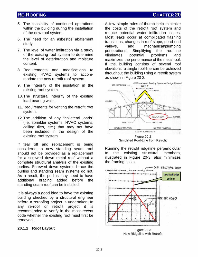
RE-ROOFING CHAPTER 20 5. The feasibility of continued operations
within the building during the installation of the new roof system.
6. The need for an asbestos abatement study.
7. The level of water infiltration via a study of the existing roof system to determine the level of deterioration and moisture content.
8. Requirements and modifications to existing HVAC systems to accom-modate the new retrofit roof system.
9. The integrity of the insulation in the existing roof system.
10. The structural integrity of the existing load bearing walls.
11. Requirements for venting the retrofit roof system.
12. The addition of any "collateral loads" (i.e. sprinkler systems, HVAC systems, ceiling tiles, etc.) that may not have been included in the design of the existing roof system.
If tear off and replacement is being considered, a new standing seam roof should not be provided as a replacement for a screwed down metal roof without a complete structural analysis of the existing purlins. Screwed down systems brace the purlins and standing seam systems do not. As a result, the purlins may need to have additional bracing added before the standing seam roof can be installed.
It is always a good idea to have the existing building checked by a structural engineer before a reroofing project is undertaken. In any re-roof or retrofit project it is recommended to verify in the most recent code whether the existing roof must first be removed.
20.1.2 Roof Layout
A few simple rules-of-thumb help minimize the costs of the retrofit roof system and reduce potential water infiltration issues. Most leaks occur at complicated flashing transitions, changes in roof slope, dead-end valleys, and mechanical/plumbing penetrations. Simplifying the roof-line eliminates potential problems and maximizes the performance of the metal roof. If the building consists of several roof elevations, a single roof-line can be achieved throughout the building using a retrofit system as shown in Figure 20-2.
Figure 20-2
Simplified Roof-Line from Retrofit
Running the retrofit ridgeline perpendicular to the existing structural members, illustrated in Figure 20-3, also minimizes the framing costs.
Figure 20-3
New Ridgeline with Retrofit
©MBMA Metal Roofing Systems Design Manual
©MBMA Metal Roofing Systems Design Manual
20-2

RE-ROOFING CHAPTER 20
Installer Note
"What If the Existing Roofing is Wet?"
It is not unusual for the existing roofing materials to be wet in some areas. (Re-roofing would not normally be done if the old roof were not leaking.) By nature of their design and installation, all metal roofs create open areas which provide some ventilation. Metal systems involving a new slope-build-up substructure always create a plenum space. Regardless of height dimensions, this space is treated as an attic by all model codes, and it is vital that it be vented accordingly. Because the space is ventilated to exhaust moist air, the existing roof assembly will dry out rather quickly; just how quickly depends upon how much moisture is present, the specifics of the ventilation of the plenum space, and the climate at the project site. If wet roofing is encountered during the retrofit work, its location should be noted so that drying can be monitored, if necessary or desired, following construction. For more information on ventilation, see Section 8.1 Ridge Vents – Types and Applications, and Section 10.3.2 Ventilation.
There should be some concern regarding the type of fastener used when making attachments through wet roofing materials, as the wet material can greatly accelerate fastener corrosion. The fastener must be sufficiently corrosion-resistant to withstand the exposure to the moisture during the period in which the drying takes place, usually between two and ten weeks. If plated fasteners are used for routine fastening, it may be advisable to switch to stainless steel when encountering wet areas.
On some re-roofing installations, additional support members must be added to the base. Base structural members of the retrofit system are primarily used to:
1. Span between other structural members
2. Provide continuous attachment to the existing structure (Figure 20-4)
Figure 20-4 Re-Roofing Base Channel Support Structure
(Direct Attachment)
If the base structural member is running parallel to the existing deck flutes, reinforcement of the deck flutes may be necessary at existing structural locations to support the retrofit system. This can be seen and is illustrated in Figure 20-5.
Figure 20-5 Reinforcement of Deck Flutes on Retrofit
©MBMA Metal Roofing Systems Design Manual
©MBMA Metal Roofing Systems Design Manual
20-3

RE-ROOFING CHAPTER 20 20.2 Existing Roof Preparation
One of the benefits of choosing a metal roof to re-cover an existing roof is that the existing roof surface can normally remain in place. This saves many hours of labor, and landfill costs; however, there are still things an installer must do in order to prepare the roof for re-cover.
The following activities are applicable to any re-roofing application. Additional activities may be required based on job specifics.
• Inspect the roof for damage and make the necessary repairs.
• Secure any warped or loose roofing material.
• Make sure there are no nails or other objects protruding from the roof that might puncture new underlayment or damage the new roof panels.
• Remove all moss and other debris from the roof.
• Cut off any overhanging roofing so that it is flush with the roof deck; also remove all hip and ridge caps.
20.3 Installation Differences
While the results of a re-roofing are the same, there are installation differences based on which method is used. A retrofit normally requires more material and many different activities involving the sub-structure. A metal overlay often involves the installer in activities which are in close or direct contact with the existing roof surface.
20.3.1 Metal Overlays
A metal roof may be installed over existing roofs of shingles/shakes/slate, single ply, built-up and bituminous materials. Codes allow a metal roof to be applied over
another metal roof. Metal-over-metal installations are shown in Figure 20-6.
Figure 20-6 Metal-over-Metal Overlays Are Permitted
During a typical metal overlay installation, the installer performs the following steps as shown in Figures 20-7, 20-8, 20-9, and 20-10:
20-4

RE-ROOFING CHAPTER 20
Figure 20-7 Step 1 - Metal overlays require smooth flat surfaces
and preparation should begin with the activities mentioned in Section 20.2, Existing Roof
Preparation.
Figure 20-8
Step 2 - Purlins of 2x2 or 2x4 lumber (left), pre-formed metal structural material (right),or pre-
notched sub-purlins as seen in Fig. 20-10, are installed as shown.
Figure 20-9
Step 3 - Older roofs often have inadequate thermal protection and new energy codes require higher
alternative thermal protection. Therefore, insulation is often installed between the purlins.
Figure 20-10
Step 4 - New metal roof panels are then attached, secured at the purlins.
Figure 20-11
Retrofit Examples
20.3. 2 Retrofit
Retrofit re-covering of an existing roof not only restores the roof's performance, but is used to change and alter the roof's slope and other, more visual, characteristics. Figure 20-11 illustrates how a retrofit
20-5

RE-ROOFING CHAPTER 20 installation changes an existing structure's roof and its appearance.
The new roof slope may require siding to be applied at endwall or sidewall locations, attached to the new retrofit framing system. In order to attach wall sheets to endwalls or sidewalls, the manufacturer may provide wall girts as shown in Figure 20-12. Girts are usually zees or hat sections that span horizontally from retrofit column-to-column at a designated spacing which meets the wind loads for the wall panel selected.
Figure 20-12
Retrofit Endwall Installation
A retrofit installation also provides the opportunity to change the roof appearance by easily adding overhangs as part of the new roof system. A typical endwall installation is illustrated in Figure 20-13.
To form an overhang at the eave, a support member must be added to cantilever beyond the wall line. A small truss frame system can be designed to attach directly to the existing wall. A typical installation example is illustrated in Figure 20-14.
Note Before performing a retrofit, check and verify which building codes may apply.
Figure 20-13
Endwall Overhang Added During Retrofit
©MBMA Metal Roofing Systems Design Manual
©MBMA Metal Roofing Systems Design Manual
20-6

RE-ROOFING CHAPTER 20
Figure 20-14
Sidewall Overhang Added During Retrofit
Summary
It is well known that metal roofs provide an installer with a large number of opportunities in new construction, but they also provide rich opportunities in the replacement roof market. The two re-covering methods described in this chapter not only allow an installer to restore a roof's performance; but alter the look and profile of an entire structure. Understanding and following the few differences in preparation and installation during a re-roofing project will enable the installer to succeed whether installing a new roof or replacing one.
Notes: _________________________________________________________________________________________________________________________________________________________________________________________________________________________________________________________________________________________________________________________________________________________________________________________________
________________________________________________________________________________________________________________________________________________________________________________________________________________________________________________________________________________________________________________________________________________________________________________________________________________________________________________________________________________________________________________________________________________________________________________________________________________________________________________________________________________________________________________________________________________________________________________________________________________________________________________________________________________________________________________________________________________________________________________________________________________________________________________________________________________________________________________________________________________________________________________________________________________________________________________________________________________________________________________________________________________________________________________________________________________________________________________________________________________________________________________________________________________________________________________________________________________________________________________________________________________________________________________________________________________
©MBMA Metal Roofing Systems Design Manual
20-7

GLOSSARY APPENDIX 1
Abrasion resistance The ability to resist being worn away by contact with another moving, abrasive surface, such as foot traffic, mechanical equipment, wind-blown particles, etc. Absorption The ability of a material to accept within its body quantities of gases or liquid, such as moisture. Accelerated weathering The exposure of a specimen to a specified test environment for a specified time with the intent of producing in a shorter time period the effects similar to actual weathering. Acid etch In waterproofing, the use of a strong acid to remove the surface of concrete to expose the aggregate. Acrylic coating A liquid coating system based on an acrylic resin. Generally, a water-based coating system that cures by air drying. Acrylic resin Polymers of acrylic or methacrylic monomers. Often used as a base for coating systems. Active metal (anodic) A metal or material that readily gives up electrons to a cathodic (noble) material. (See Anodic.) An active metal will corrode in the presence of moisture when in contact with a cathodic metal. Adhesion Steady or firm attachment. Adhesive bond break A material to facilitate independent movement between two units that would otherwise bond together.
Aggregate (1) Crushed stone, crushed slag, or water-worn gravel used for surfacing a built-up roof system; (2) Any granular material. Aged R-value Thermal resistance value established by utilizing artificial conditioning procedures for a prescribed time period. Air leakage The unintended movement of air from a location where it is intended to be contained to another location. Alligatoring The cracking of the surfacing bitumen on a bituminous roof or coating on a SPF roof, producing a pattern of cracks similar to an alligator's hide; the cracks may not extend completely through the surfacing bitumen or coating. Aluminized steel Sheet steel with a thin aluminum coating bonded to the surface to enhance weathering characteristics. Aluminum A nonrusting, malleable metal sometimes used for metal roofing and flashing. Anodic A metal or material that readily gives up electrons to a cathodic material in the presence of an electrolyte. (See Galvanic series.) Anti-Capillary hem A hem used in a metal panel seam to reduce the potential for water migration. Application rate The average quantity (mass, volume, or thickness) of material applied per unit area. Apron flashing Term used for a flashing located at the
A1-1
GLOSSARY APPENDIX 1
juncture of the top of a sloped roof and a vertical wall, chimney, or steeper-sloped roof. Architectural panel A metal roof panel, typically a double standing seam or batten seam; generally requires solid decking underneath and relies on slope to shed water. Also see Non-structural Panel. Architectural shingle An asphalt shingle that provides a dimensional appearance. (see also Dimensional Shingle and Laminated Shingle) Area divider A raised, flashed assembly; typically a single- or double-wood member attached to a wood base plate that is anchored to the roof deck. It is used to accommodate thermal stresses in a roof system where an expansion joint is not required, or to separate large roof areas or separate roof systems comprised of different/ incompatible materials, and may be used to facilitate installation of tapered insulation. Area practices Design or application techniques peculiar to a specific geographical region. Asbestos A group of natural, fibrous impure silicate materials. Asphalt A dark brown or black substance found in a natural state or, more commonly, left as a residue after evaporating or otherwise processing crude oil or petroleum. Asphalt may be further refined to conform to various roofing grade specifications:
Dead-level asphalt A roofing asphalt conforming to the requirements of ASTM Specification D 312, Type I.
Flat asphalt A roofing asphalt conforming to the requirements of ASTM Specification D 312, Type II. Steep asphalt A roofing asphalt conforming to the requirements of ASTM Specification D 312, Type III. Special steep asphalt A roofing asphalt conforming to the requirements of ASTM specification D312, Type IV.
Asphalt, Air blown Asphalt produced by blowing air through molten asphalt to raise its softening point and modify other properties. Asphalt emulsion A mixture of asphalt particles and emulsifying agent, such as bentonite clay and water. Asphalt felt An asphalt-saturated and/or asphalt-coated felt. (See Felt.) Asphalt primer See Primer. Asphalt roof cement A trowelable mixture of solvent-based bitumen, mineral stabilizers, other fibers and/or fillers. Classified by ASTM Standard D2822-1 Asphalt Roof Cement, and D4586-2 Asphalt Roof Cement, Asbestos-Free, Types I and II. Type I is sometimes referred to as "plastic cement," and is made from asphalt characterized as self-sealing, adhesive and ductile, and conforming to ASTM Specification D312, Type I; Specification D449, Types l or II; or Specification D946. (See Plastic cement and flashing cement.)
A1-2

GLOSSARY APPENDIX 1
Type II is generally referred to as "vertical-grade flashing cement," and is made from asphalt characterized by a high softening point and relatively low ductility, and conforming to the requirement of ASTM Specification D312, Types II or III; or Specification 0 449, Type III. (See Plastic cement and flashing cement.)
Asphalt shingle A shingle manufactured by coating a reinforcing material (felt or fibrous glass mat) with asphalt and having mineral granules on the side exposed to the weather. (See Shingle) Asphaltene A high molecular weight hydrocarbon fraction precipitated from asphalt by a designated solvent (paraffinic naphtha) at a specified temperature and solvent-asphalt ratio. Atactic polypropylene A group of high molecular weight polymers formed by the polymerization of propylene. Attic The cavity or open space above the ceiling and immediately under the roof deck of a steep-sloped roof. AZ50 A popular coating thicknesses for Galvalume Steel similar to the G90 coating used on galvanized steel. Back-nailing (also referred to as "Blind-nailing") The practice of blind nailing the back portion of a roofing ply, steep roofing unit or other components in a manner so that the fasteners are covered by the next sequential ply, or course, and are not exposed to the weather in the finished roof system. Ballast A material, such as aggregate or precast concrete pavers, which employs its mass
and the force of gravity to hold (or assist in holding) single-ply roof membranes in place. Bar joist (See Steel joist.) Barrel vault A building profile featuring a rounded profile to the roof on the short axis, but with no angle change on a cut along the long axis. Barrier board Noncombustible board stock material of low thermal conductivity placed between two elements of a roof assembly. Base flashing (membrane base flashing) Plies or strips of roof membrane material used to close-off and/or seal a roof at the horizontal-to-vertical Intersections, such as at a roof-to-wall juncture. Membrane base flashing covers the edge of the field membrane. (See Flashing.) Base ply The bottom or first ply in a built-up roof membrane when additional plies are to be subsequently installed. Base sheet An impregnated, saturated, or coated felt placed as the first ply in some low-slope roof systems. Batten (1) Cap or cover; (2) In a metal roof, a metal closure set over, or covering the joint between, adjacent metal panels; (3) In a wood roof, a strip of wood usually set in or over the structural deck, used to elevate and/or attach a primary roof covering such as tile; (4) In a single ply membrane roof system, a narrow plastic, wood or metal bar that is used to fasten or hold the roof membrane and/or base flashing in place.
A1-3

GLOSSARY APPENDIX 1
Batten seam A metal panel profile attached to and formed around a beveled wood or metal batten. Bentonite A porous clay formed by the decomposition of volcanic ash that swells 5 to 6 times its original volume in the presence of water. Bermuda seam A metal panel profile featuring a stepdown profile that runs perpendicular to the slope of the roof. Bird bath Random amounts of residual water on a roof membrane. Bitumen (1) A class of amorphous, black or dark colored (solid semi-solid or viscous) cementitious substances natural or manufactured, composed principally of high molecular weight hydrocarbons, soluble in carbon disulfide and found in asphalts, tars, pitches and asphaltenes; (2) A generic term used to denote any material composed principally of bitumen, typically asphalt or coal tar.
Bitumen-stop (See Envelope or bleed-sheet.) Bituminous coating A bituminous material used as a coating between two dissimilar materials. Typically used for corrosion protection and sound reduction. Bituminous emulsion A suspension of minute particles of bituminous material in water. Blackberry (also referred to as "Blueberry" or "Tarboil") A small bubble or blister in the flood coat of an aggregate-surfaced built-up roof membrane.
Blanket (batt) insulation Glass fiber or other compressible fibrous insulation, generally available in roll form. Bleed-sheet A sheet material used to prevent the migration of bitumen. Bleeder strip (See Rake-starter.) Blind-nailing The use of nails that are not exposed to the weather in the finished roofing system. Blister An enclosed pocket of air, which may be mixed with water or solvent vapor, trapped between impermeable layers of felt or membrane, or between the membrane and substrate. Blocking Sections of wood (which may be preservative treated) built into a roof assembly, usually attached above the deck and below the membrane or flashing, used to stiffen the deck around an opening, act as a stop for insulation, support a curb, or serve as a nailer for attachment of the membrane and/or flashing. Blowing agent An expanding agent used to produce a gas by chemical or thermal action, or both, in manufacture of hollow or cellular materials. Bond The adhesive and/or cohesive forces holding two components in positive contact. Boot (1) A covering made of flexible material, which may be preformed to a particular shape, used to exclude dust, dirt, moisture, etc., from around a penetration; (2) A flexible material used to form a closure, sometimes installed at inside and outside corners.
A1-4

GLOSSARY APPENDIX 1
Brake Hand- or power-activated machinery used to bend metal. Bridging (1) When membrane or base flashing is unsupported at a juncture; (2) Bridging in steep-slope roofing occurs when reroofing over standard-sized asphalt shingles with metric-sized asphalt shingles. British thermal unit (BTU) The heat energy required to raise the temperature of 1 pound of water degree Fahrenheit (joule). For the metric equivalent, see Joule. Broadcast Uniformly cast or distribute granular or aggregate surfacing material. Brooming To improve the embedding of a ply or membrane by using a broom or squeegee to smooth it out and ensure contact with the adhesive under the ply or membrane. Buckle An upward, elongated displacement of a roof membrane frequently occurring over insulation or deck joints. A buckle may be an indication of movement within the roof assembly. Building code The minimum construction requirements established generally by national organizations of experts and adopted completely or in altered form by local governing authorities. Built-up roof (BUR) A continuous, semi-flexible roof membrane, consisting of multiple plies of saturated felts, coated felts, fabrics, or mats assembled in place with alternate layers of bitumen, and surfaced with mineral aggregate, bituminous materials, a liquid-applied coating or a
granule-surfaced cap sheet. Bundle An individual package of metal panels, shakes, or shingles. Bun stock Large solid box-like structure formed during the production of polystyrene insulation; individual board stock pieces are then cut from the bun. Butt joint A joint formed by adjacent, separate sections of material, such as where two neighboring pieces of insulation abutt. Button punch A process of indenting two or more thicknesses of metal that are pressed against each other to prevent slippage between the metal. Butyl Rubber-like material produced by polymerizing isobutylene. Butyl coating An elastomeric coating system derived from polymerized isobutylene. Butyl coatings are characterized by low water vapor permeability. Butyl rubber A synthetic elastomer based on isobutylene and a minor amount of isoprene. It can be vulcanized and features low permeability to gases and water vapor. Butyl tape A sealant tape used between metal roof panel seams and/or end laps; also used to seal other types of sheet metal joints, and in various sealant applications. Calender (1) To press between rollers or plates in order to smooth and glaze, or to thin into sheets; (2) A machine for calendering.
A1-5

GLOSSARY APPENDIX 1
Camber A slight convexity, arching, or curvature (as of a rafter, joist, or substructure). Canopy Any overhanging or projecting roof structure, typically over entrances or doors. Cant In SPF-based roofing, a beveling of foam at horizontal/vertical joints to increase strength and promote water runoff. Cant strip A beveled strip used under flashings to modify the angle at the point where the roofing or waterproofing membrane meets any vertical element. Cap flashing (1) Usually composed of metal, used to cover or shield the upper edges of the membrane base flashing wall flashing; (2) A flashing used to cover the top of various buildings components, such as parapets or columns. (See Flashing and coping.) Cap sheet A sheet, often granule-surfaced, used as the top ply of some built-up or modified bitumen roof membranes and/or flashings. Capacitance meter A device used to locate moisture or wet materials within a roof system by measuring the ratio of the change to the potential difference between two conducting elements separated by a non-conductor. Capillary action (1) The action by which the surface of a liquid, where it is in contact with a solid, is elevated or depressed depending on the relative attraction of the molecules of the liquid for each other and for those of the solid; (2) The siphoning of liquid into a joint or void between two adjacent surfaces.
Catalyst An ingredient that initiates a chemical reaction or increases the rate of a chemical reaction when combined with another chemical. Cathodic A metal or material that readily attracts electrons from an anodic material in the presence of an electrolyte. (See Galvanic series.) Caulk A composition of vehicle and pigment used at ambient temperatures for filling/sealing joints or junctures, that remains elastic for an extended period of time after application. Caulking (1) The physical process of sealing a joint or juncture; (2) Sealing and making weather-tight the joints, seams or voids between adjacent surfaces by filling with a sealant. Cavitation The formation of a partial vacuum or cavity in a liquid. Cavity wall An exterior wall usually of masonry, consisting of an outer and inner withe separated by a continuous air space, but connected together by wire or sheet-metal tiles. CDX A grade of plywood in which the letter C specifies that one face of the plywood is a veneer of grade C, which contains small knots and knotholes or splits that may have been plugged and sanded smooth. The other face is a veneer of grade D, which can contain larger knots and may include open splits and holes. The letter X signifies that the adhesive used to make the plywood is waterproof.
A1-6

GLOSSARY APPENDIX 1
Cee-channel A structural framing member formed into the shape of the letter "c." Cellular glass insulation A rigid closed-cell insulation board made from crushed glass and hydrogen sulfide gas. Cementitious waterproofing Heavy cement-based compounds and various additives that are mixed and packaged for use in a dry form; the packaged mixture is then mixed with water and liquid bonding agents to a workable concrete-like consistency. Centipoise A unit of measure of absolute viscosity. (The viscosity of water is one centipoise. The lower the number, the less viscous the material.) Centistoke A unit of viscosity; the ratio of a liquid's absolute viscosity to the density of that liquid. Chalk A powdery residue on the surface of a material. Chalk line A line made on the roof or other flat surface by snapping a taut string or cord dusted with colored chalk. Chalking The formation of a powdery surface condition from the disintegration of a binder or elastomer. Channel flashing In steep-slope roof construction, a type of flashing used at roof-to-wall junctures and other roof-to-vertical plane intersections where an internal gutter is needed to handle runoff. Commonly used with profile tile.
Chemical resistance The ability to withstand contact with specified chemicals without a significant change in properties. Chimney Stone, masonry, prefabricated metal or woodframed structure, containing one or more flues, projecting through and above the roof. Chlorinated polyethylene (CPE) A thermoplastic material, used for single-ply roof membranes, composed of high molecular weight polyethylene that has been chlorinated with a process that yields a flexible rubber-like material. Chlorosulfonated polyethylene (CSPE or CSM) Probably best known by the DuPont trade name Hypalon'", a synthetic, rubber-like thermoset material, based on high molecular weight polyethylene with sulphonyl chloride, usually formulated to produce a self-vulcanizing membrane. Classified by ASTM Standard D5019. Cladding A material used as the roof or exterior wall enclosure of a building. Cleat A continuous strip, or angled piece, used to secure metal components. (See Clip.) Clerestory An upward extension of enclosed space created by carrying a setback vertical wall (typically glazed) up and through the roof slope. Two intersecting shed roofs on different planes. Clip A component or angle piece used to secure two or more metal components together. (See Cleat.)
A1-7

GLOSSARY APPENDIX 1
Clipped gable A gable cutback near the peak in a hiproof form. CIosed-cut valley A method of valley application in which shingles from one side of the valley extend across the valley, while shingles from the other side are trimmed back approximately two inches (51 mm) from the valley centerline. Closure strip A metal or resilient strip, such as neoprene foam, used to close openings created by joining metal panels or sheets and flashings. Coal tar A dark brown to black colored, semi-solid hydrocarbon produced by the distillation of coal. Coal tar pitch is further refined to conform to the following roofing grade specifications:
Coal tar pitch A coal tar used as the waterproofing agent In dead-level or low-slope built-up roof membranes and membrane waterproofing systems, conforming to ASTM Specification D450, Type I. Coal tar waterproofing pitch A coal tar used as the dampproofing or waterproofing agent in below-grade structures, conforming to ASTM Specification D450, Type II.
Coal tar bitumen A proprietary trade name for Type III coal tar used as the dampproofing or waterproofing agent In dead-level or low-slope built-up roof membranes and membrane waterproofing systems, conforming to ASTM D450, Type III.
Coal tar felt A felt that has been saturated or impregnated with refined coal tar.
Coal tar roof cement A trowel able mixture of processed coal tar base, solvents, mineral fillers and/or fibers. Classified by ASTM Standard D 4022, "Coal Tar Roof Cement, Asbestos Container." Coarse orange peel surface texture A surface showing a texture where nodules and valleys are approximately the same size and shape. This surface is acceptable for receiving a protective coating because of the roundness of the nodules and valleys. Coated base sheet A coated felt intended to be used as a base ply in a built-up or modified bitumen roof membrane. Coated fabric Fabrics that have been impregnated and/or coated with a plastic-like material in the form of a solution, dispersion hot-melt, or powder. The term also applies to materials resulting from the application of a pre-formed film to a fabric by means of calendaring. Coated felt (Sheet) (1) An asphalt felt that has been coated on both sides with harder, more viscous asphalt; (2) A glass fiber felt that has been simultaneously impregnated and coated with asphalt on both sides.
Coating A layer of liquid or solid material applied to a surface for protection or appearance. Cobwebbing A phenomenon observed during spray application characterized by the formation of web-like threads along with the usual droplets leaving the spray gun nozzle. Code A collection of laws (regulations, ordinances or statutory requirements) adopted by governmental authority. (See Building code
A1-8

GLOSSARY APPENDIX 1
and Model code.) Coefficient of thermal expansion The coefficient of change in dimension of a material per unit of dimension per degree change in temperature. Cohesion The molecular forces of attraction by which the body of a material is held together. Coil coating The application of a finish to a coil of metal using a continuous mechanical coating process. Cold forming The process of shaping metal into desired profiles without the application of heat. Cold rolled The process of forming steel into sheets, panels, or shapes on a series of rollers at room temperature. Cold roof assembly A roof assembly configured with the insulation below the deck, not typically in contact with the deck, allowing for a ventilation space. The temperature of the roof assembly remains close to the outside air temperature. Color stability The ability of a material to retain its original color after exposure to weather. Column In structures, a relatively long, slender structural compression member such as a post, pillar, or strut; usually vertical which acts in (or near) the direction of its longitudinal axis. Combing ridge A term used to describe an installation of finishing slate or wood at the ridge of a roof whereby the slates on one side project
beyond to the apex of the ridge. Combustible Capable of burning. Combustion A chemical process of oxidation that occurs at a rate fast enough to produce heat and usually light, either as glow or flames; the process of burning. Compatible materials Two or more substances that can be mixed, blended, or attached without separating, reacting, or affecting the materials adversely. Composite board roof insulation Rigid board insulation generally comprised of perlite or wood fiberboard factory bonded to polyisocyanurate or polystyrene. Compounded thermoplastics A category of roofing membranes made by blending thermoplastic resins with plasticizers, various modifiers, stabilizers, flame retardants, UV absorbers, fungicides and other proprietary substances alloyed with proprietary organic polymers. Compressive strength The property of a material that relates to its ability to resist compression loads. Concealed-nail method A method roofing application in which all nails are driven into the underlying course of roofing and covered by a subsequent, overlapping course. Concealed plate (See Cover plate.) Condense To make denser or more compact, as when a material (e.g., water vapor) changes from its gas phase to its liquid phase.
A1-9

GLOSSARY APPENDIX 1
Condensate The liquid resulting from the condensation of a gas. Condensation The conversion of water vapor or other gas to liquid phase as the temperature drops; the act or process of condensing. Conditioning The storage of a material specimen under specified temperature, humidity, etc. for a specified time prior to testing. Conductance, Thermal The thermal transmission in unit time through unit area of a particular body or assembly having defined surfaces, when unit average temperature difference is established between the surfaces. C = Btu / h • ft2 • °F (C = W / m2 • °K). Conductor head An enlargement or catch basin at the top of a downspout or leader to receive rainwater from a gutter or scupper. Construction joint (1) A joint where two successive placements of concrete meet; (2) A separation provided in a building which allows its component parts to move with respect to each other. Contact cements Adhesives used to adhere or bond various roofing components. These adhesives adhere mated components immediately on contact of surfaces to which the adhesive has been applied. Contamination The process of making a material or surface unclean or unsuited for its intended purpose, usually by the addition or attachment of undesirable foreign substances. Control joint A groove which is formed, sawed, or tooled
in a concrete or masonry structure to regulate the location and amount of cracking and separation resulting from the dimensional change of different parts of the structure, thereby avoiding the development of high stresses. Coping The covering piece on top of a wall exposed to the weather, usually made of metal, masonry, or stone and sloped to carry off water. Copolymer The product of polymerization of two or more substances (as two different isomers) together. Copolymerization A chemical reaction that results in the bonding of two or more dissimilar monomers to produce large, long-chain molecules that are copolymers. Copper A naturally weathering metal used in metal roofing or flashing; typically used in 16 ounce per square foot (0.56 mm) and 20 ounce per square foot (0.69 mm) thicknesses. Core cut or core sample (1) A sample from a low-slope roof system taken for the purpose of obtaining primarily qualitative information about its construction. Typically, core cut analysis can verify or reveal the type of membrane surfacing; the type of membrane, the approximate number of plies; the type, thickness and condition of the insulation (if any): and the type of deck used as a substrate for the roof system. (2) For SPF-based roof systems, core cuts are used to obtain both quantitative and qualitative information, such as the thickness of the foam, the thickness and adhesion of the coating, thickness of individual passes and adhesion between passes and the adhesion of the foam to its substrate.
A1-10

GLOSSARY APPENDIX 1
Cornice The decorative horizontal molding or projected roof overhang. Counter batten Vertical wood strips installed on sloped roofs over which horizontal battens are secured. The primary roof covering is attached or secured to these horizontal battens. Counterflashing Formed metal or elastomeric sheeting secured on or into a wall, curb, pipe, rooftop unit or other surface, to cover and protect the upper edge of a base flashing and its associated fasteners. Course (1) The term used for a row of roofing material that forms the roofing, waterproofing or flashing system; (2) one layer of a series of materials applied to a surface (e.g., a five-course wall flashing is composed of three applications of roof cement with one ply of felt or fabric sandwiched between two layers of roof cement). Cover board An insulation board used over closed cell plastic foam insulation (e.g., polyiso-cyanurate) to prevent blistering when used in conjunction with hot bituminous membranes. Suitable cover board insulation are glassfaced siliconized gypsum board, glass-fiber board, perlite board, wood-fiber board or mineral-fiber board. Cover boards are also recommended between polyisocyanurate Insulation and Single ply membranes to protect the polyisocyanurate. Cover plate A metal strip sometimes installed over or under the joint between formed metal pieces. Coverage The surface area uniformly covered by a specific quantity of a particular material at a specific thickness.
Crack A nonlinear separation or fracture occurring in a material. Cream time Time in seconds (at a given temperature) when the A and B components of polyurethane foam will begin to expand after being mixed. Recognizable as a change in color of the materials. Cricket A relatively small area of a roof constructed to divert water from a horizontal intersection of the roof with a chimney, wall, expansion joint or other projection. (See Saddle.) Cross-linking The formation of chemical bonds between polymeric chains. Cross-linking of rubber is referred to as vulcanization or "curing." Crystalline waterproofing A compound of cement quartz or silica sand, and other active chemicals that are mixed and packaged for use in a dry powder form; the packaged mixture is then mixed with water and applied to a concrete surface where it penetrates into the pores of concrete. Cupola A relatively small roofed structure, generally set on the edge or peak of a main roof area for ventilation or aesthetic purposes. Curb (1) A raised member used to support roof penetrations, such as skylights, mechanical equipment, hatches, etc. above the level of the roof surface; (2) A raised roof perimeter relatively low in height. Cure A process whereby a material is caused to form permanent molecular linkages by exposure to chemicals eat, pressure and/or weathering.
A1-11

GLOSSARY APPENDIX 1
Cure time The time required for a material to reach its desirable long-term physical characteristics. Cured concrete Concrete that has attained its intended design performance properties. Curing agent An additive in a coating or adhesive that results in increased chemical activity between the components with an increase or decrease in rate of cure. Curing compound A liquid that is sprayed or otherwise applied to newly placed concrete which retards the loss of water during curing. Curved roof A roof whose panels are mounted on a barrel or dome support. Cutback Solvent-thinned bitumen used in cold-process roofing adhesives, roof cements and roof coatings. Cutoff A permanent detail designed to prevent lateral water movement in an insulation system and used to isolate sections of a roofing system. (Note: A cutoff is different from a tie-in, which may be a temporary or permanent seal.) (See Tie-In.) Cutout The open portions of a strip shingle between the tabs. Sometimes referred to as a keyway. Dampproofing Treatment of a surface or structure to resist the passage of water in the absence of hydrostatic pressure. Dead level Absolutely horizontal or zero slope. (See Slope.)
Dead-level asphalt (See Asphalt.) Dead loads The weight of a structure itself, including the weight of fixtures or equipment permanently attached to it. Deck A structural component of the roof of a building. The deck must be capable of safely supporting the design dead and live loads, including the weight of the roof system's additional live loads required by the governing building codes, and provide the substrate to which the roofing or waterproofing system is applied the structural surface of a building to which a roof assembly is installed. Decks are either non-combustible (e.g., corrugated metal, or concrete) or combustible (e.g., wood plank or plywood). Deflection (bowing, sagging) (1) The deformation of a structural member as a result of loads acting on it: (2) Any displacement in a body from its static position, or from an established direction or plane, as a result of forces acting on the bod.
Degradation A harmful change in the chemical structure, physical properties or appearance of a material from natural or artificial exposure (e.g., exposure to radiation moisture, heat, freezing, wind, ozone, oxygen, etc.). Degree days A unit used in estimating the fuel consumption for a building; equal to the number of degrees that the mean temperature, for a 24-hour day, is below the "base temperature"; the base temperature is taken as 65° F (18.3° C) in the U.S.A. Delamination Separation of the laminated layers of a component or system.
A1-12

GLOSSARY APPENDIX 1
Design loads The total load on a structural system for the most severe combination of loads and forces which it is designed to sustain. Dew-point temperature The temperature at which air becomes saturated with water vapor. The temperature at which air has a relative humidity of 100%. Diaphragm A floor slab, metal wall panel, roof panel, or the like having a sufficiently large in-plane shear stiffness and sufficient strength to transmit horizontal forces to resisting systems. Diffusion The movement of water vapor from regions of high concentration (high water vapor pressure) toward regions of lower concentration. Dimensional shingle A shingle that is textured, overlayed, or laminated and designed to produce a three dimensional effect. (also see Laminated shingle and Architectural shingle.) Dimensional stability The degree to which a material maintains its original dimensions when subjected to changes in temperature and humidity. Diverter An upslope barrier to water often installed in close proximity to chimneys, curbs, or other roof obstructions, in order to direct drainage. Dormer A structure projecting from a sloping roof usually housing a window or ventilating louver. Double coverage Application of asphalt, slate, or wood rooting such that the lapped portion is at
least 2 inches (50 mm) wider than the exposed portion, resulting in two layers of roofing material over the deck. Double lock standing seam In a metal roof panel or metal cap, a standing seam that uses a double overlapping interlock between two metal panels. (See Standing seam.) Double pour To apply two layers or flood coats of bitumen and aggregate to a built-up roof. Downspout A vertical pipe or conduit used to carry runoff water from a scupper, conductor head, or gutter of a building to a lower roof level or to the ground or storm water runoff system. Drag load The external force (e.g., from the weight of ice and snow) applied to a steep-slope roof system component forcing the component downslope. Drain An outlet or other device used to collect and direct the flow of runoff water from a roof area. Drip edge A metal flashing or other overhanging component with an outward projecting lower edge, intended to control the direction of dripping water and help protect underlying building components. Dry (1) Free or relatively free from a liquid, especially water; (2) To remove water or moisture. Dry bulb temperature The temperature of air as measured by an ordinary thermometer.
A1-13

GLOSSARY APPENDIX 1
Dry film thickness The thickness, expressed in mils, of an applied and cured coating or mastic. For comparison, see Wet film thickness. Drying time The time required for the loss of volatile components so that the material will no longer be adversely affected by weather conditions such as dew, rain, or freezing. Dual level drain In waterproofing, an outlet or other device with provisions for drainage at both the wearing surface and waterproofing membrane levels used to collect and direct the flow of runoff water from a horizontal slab. Dynamic load Any load which is nonstatic, such as a wind load or moving live load. Eave The lower edge of a sloping roof that part of a roof which projects beyond the wall. Eave height The vertical dimension from finished grade to the eave. Eave-trough See Gutter. Edge stripping Membrane flashing strips cut to specific widths used to seal/flash perimeter edge metal and the roof membrane application of felt strips cut to narrower widths than the normal felt-roll width to cover a joint between metal perimeter flashing and built-up roofing. Edge venting The practice of providing regularly spaced or continuously protected (e.g., louvered) openings along a roof edge or perimeter. used as part of a ventilation system to dissipate heat and moisture vapor.
Efflorescence An encrustation of soluble salts, commonly white, deposited on the surface of stone, brick, plaster, or mortar; usually caused by free alkalies leached from mortar or adjacent concrete as moisture moves through it. Elasticity The property of a body that causes it to tend to return to its original shape after deformation (as stretching, compression, or torsion). Elastomer A macromolecular material that returns rapidly to its approximate initial dimensions and shape after substantial deformation by a weak stress and subsequent release of that stress. Elastomeric coating A coating that is capable of being stretched at least twice its original length (100 percent elongation) and. recovering to its original dimensions. Elongation The ratio of the extension of a material to the length of the material prior to stretching. Embedment (1) The process of pressing/positioning a felt, aggregate, fabric, mat, or panel into hot bitumen or adhesive to ensure intimate contact at all paints; (2) The process of pressing/positioning granules into coating in the manufacture of factory-prepared roofing, such as shingles. Embossed To raise a design, or pattern, on (a blank) with dies of similar pattern, one the negative of the other. Embrittlement The loss of flexibility or elasticity of a material.
A1-14

GLOSSARY APPENDIX 1
Emulsion A mixture of bitumen and water, with uniform dispersion of the bitumen or water, globules, usually stabilized by an emulsifying agent or system. End lap The distance of overlap where one ply, pane, or piece extends beyond the end of the immediately adjacent underlying ply, panel, or piece. Energy star A joint program of the U.S. Environmental Protection Agency and the U.S. Department of Energy helping us save money and protect the environment through energy efficient products and practices. Envelope (Bitumen-stop) A continuous membrane edge seal formed at the perimeter and at penetrations by folding the base sheet or ply over the plies above and securing it to the top of the membrane. The envelope prevents bitumen seepage from the edge of the membrane. EPDM Ethylene propylene diene monomer. (See also Ethylene propylene diene terpolymer.) Epichlorohydrin (ECH) A synthetic rubber including two epichlorohydrin based elastomers. It is similar to and compatible with EPDM. Epoxy A class of synthetic, thermosetting resins that produce tough, hard, chemical-resistant coatings and adhesives. Equilibrium moisture content (EMC) The moisture content of a material stabilized at a given temperature and relative humidity, expressed as percent moisture by weight.
Ethylene propylene diene terpolymer (EPDM) Designated nomenclature of ASTM for a terpolymer of ethylene, propylene and diene. EPDM material is a thermosetting synthetic elastomer. Exhaust ventilation Air that is vented or exhausted from the roof cavity, typically through vents installed on the up slope portion of the roof. For example, with most steepslope roof assemblies, exhaust vents are typically located at or near the ridge. Exotherm Heat generated by a chemical reaction. Expansion cleat A cleat designed to accommodate thermal movement of metal roof panels. Expansion joint A structural separation between two building elements that allows free movement between the elements without damage to the roofing or waterproofing system. Exposed-nail method A method of asphalt roll roofing application in which all nails are driven into the adhered, overlapping course of roofing. Nails are exposed to the weather. Exposure (1) The traverse dimension of a roofing element or component not overlapped by an adjacent element or component in a roof covering. For example, the exposure of any ply in a built-up roof membrane may be computed by dividing the felt width, minus 2 inches (51 mm), by the number of shingled plies; thus, the exposure of 36 inch (914 mm) wide felt in a shingled, four-ply membrane should be approximately 8 inches (216 mm); (2) The dimension of sidewall or roofing covering that is not covered or
A1-15

GLOSSARY APPENDIX 1
overlapped by the up-slope course of component. The typical exposure for a standard-sized three-tab shingle is 5 inches (127 mm), depending on manufacturer specifications. Extrusion A process in which heated or unheated material is forced through a shaping orifice (a die) in one continuously formed shape, as in film, sheet, rod, or tubing. Eyebrow A dormer, usually of small size, whose roof line over the upright face is typically an arched curve, turning into a reverse curve to meet the horizontal at either end. Also, a small shed roof projecting from the gable end of the larger, main roof area. Fabric A woven cloth or material of organic or inorganic filaments, threads, or yarns used for reinforcement in certain membranes and flashings. Factory Mutual Research Corporation (FMRC) Factory Mutual Research Corporation is an organization devoted in general to property conservation. Its activities include writing internal standards; participating in the writing of consensus standards; third-party testing and approval of products; and certification of electrical apparatus for shock and fire safety. Their concern includes fire-safety, electrical, and construction-related issues. Factory seam A splice/seam made by the manufacturer during the assembly of sections of materials into larger sheets/panels. Fading Any lightening of initial color. Fall protection Critical safety equipment used in order to
avoid injuries and death due to falling from a roof or other elevation. Fallback A reduction in bitumen softening point, sometimes caused by refluxing or overheating in a relatively closed container. (See Softening point drift.) Fascia (1) In steep-slope roofing, a board that is nailed to the ends of a roof rafter; sometimes supports a gutter; (2) In low-slope roofing, the vertical or steeply sloped roof or trim located at the perimeter of a building. Typically, it is a border for the low-slope roof system. Fastener Any of a wide variety of mechanical securement devices and assemblies, including nails, staples, screws, cleats, clips and bolts, which may be used to secure various components of a roof assembly. Feathering strips Tapered wood filler strips placed along the butt ends of old wood shingles to create a relatively smooth surface when reroofing over existing wood shingle roofs. Referred to in some regions of the country as "horse feathers," or leveling strips. Felt A flexible sheet manufactured by the interlocking of fibers with a binder, or through a combination of mechanical work, moisture, and heat. Felts are manufactured principally from wood pulp and vegetable fibers (organic felts), asbestos fibers (asbestos felts), glass fibers (glass fiber felts or ply Sheets), or polyester fibers. Felt machine (Felt Layer) A mechanical device used for applying bitumen and roofing felt or ply sheet simultaneously.
A1-16

GLOSSARY APPENDIX 1
Ferrule A metal sleeve placed inside a gutter at the top. A spike or screw is nailed/screwed through the gutter face and ferrule into the fascia board to hold the gutter in place. The ferrule acts as a spacer in the gutter to maintain its original shape. Field seam A splice or seam made in the field (not factory) where overlapping sheets are joined together using an adhesive, splicing tape, or heat- or solvent-welding. Filler A relatively inert ingredient added to modify physical characteristics. Fillet A heavy bead of waterproofing compound or sealant material generally installed at the point where vertical and horizontal surfaces meet; to reduce the desired effect to take out the 90° angle at the base of a vertical flashing. Film Sheeting having a nominal thickness not greater than 10 mils (0.25 mm). Film thickness The thickness of a membrane or coating. Wet film thickness is the thickness of a coating as applied; dry film thickness is the thickness after curing. Film thickness is usually expressed in mils (thousandths of an inch). Fin A term used to describe a deck surface condition. A sharp raised edge (generally in concrete) capable of damaging a roof membrane or vapor retarder. Fine mineral-surfacing Water-insoluble, inorganic material, more than 50 percent of which passes through a No. 35 sieve. Used on the surface of various roofing materials and membranes
to prevent sticking. Fire barrier An assembly component which is rated or classified and used to provide fire resistance. Common examples are fiberglass underlayment and gypsumboard. Fire resistance The property of a material or assembly to withstand fire or give protection from it. Fire retardant treated (FRT) plywood Plywood which has been impregnated, under pressure, with mineral salts; in the event of fire, the burning wood and salts emit noncombustible gases and water vapor instead of the usual flammable vapors. Fishmouth (Also referred to as an edge wrinkle) (1) A half-cylindrical or half-conical shaped opening or void in a lapped edge or seam, usually caused by wrinkling or shifting of ply sheets during installation; (2) In metal panels or shingles, a half-conical opening formed at a cut edge. Fishmouths in an installation may be an aesthetic or a performance issue. Flaking In protective coatings, the detachment of small pieces of the coating film. Flammable Subject to easy ignition and rapid flaming combustion. Flame retardant A chemical used to impart flame resistance. Flame spread The propagation of a flame away from its source of ignition. Flammability Those characteristics of a material that pertain to its relative ease of ignition and ability to sustain combustion.
A1-17

GLOSSARY APPENDIX 1
Flange The projecting edge of a rigid or semi-rigid component, such as a metal edge flashing flange. Flash point The lowest temperature at which vapors above a volatile combustible substance ignite in air when exposed to a flame. Flashing Components used to weatherproof or seal roof system edges at perimeters, penetrations, walls, expansion Joints, valley, drains and other places where the roof covering is interrupted or terminated. For example, membrane base flashing covers the edge of the field membrane, and cap flashings or counterflashings shield the upper edges of the base flashing. Flashing cement A trowelable mixture of solvent-based bitumen and mineral stabilizers that may include asbestos or other inorganic or organic fibers. Generally, flashing cement is characterized as vertical-grade, which indicates It is Intended for use on vertical surfaces. (See Asphalt roof cement and plastic cement.) Flashing collar (Sometimes referred to as a roof jack or flashing boot) an accessory flashing used to cover and/or seal soil pipe vents and other penetrations through the roof. Flat lock A method of interlocking metal panels in which one panel edge is folded back on top of itself and the other panel is folded under, after which the two panels are hooked together. Fleece Mats or felts composed of fibers, sometimes used as a membrane backer.
Flood (pour) coat The surfacing layer of bitumen into which surfacing aggregate is embedded on an aggregate surfaced built-up roof. Flood test The procedure in which a controlled amount of water is temporarily retained over a horizontal surface to determine the effectiveness of the waterproofing system. Fluid-applied elastomer A liquid elastomeric material that cures after application to form a continuous waterproofing membrane. Fly-in Method of application for roll materials by which the dry sheet is set into the bitumen or adhesive applied to the roof surface. FM, FMR, or FMRC See Factory Mutual Research Corporation (FMRC). Foam stop The roof edge treatment upon which SPF is terminated. Force A strength or energy exerted or brought to bear because of motion or change. Froth pack A term used to describe small, disposable aerosol cans that contain SPF components. Two component froth packs are available to do small repairs for sprayed polyurethane foam-based roofs. G90 A designation for galvanized metal sheet, indicating 0.90 ounces (26 grams) of zinc per square foot, measured on both sides per ASTM A653. Gable The vertical triangular portion of the end of
A1-18

GLOSSARY APPENDIX 1
a building having a double-sloping roof, from the level of the eaves to the ridge of the roof. Gable roof A single-ridge roof that terminates at gable end(s). Galvalume Trade name for a coated steel sheet product whose coating is a metal alloy composed of aluminum, zinc, and silicone. Galvanic action An electrochemical action that generates electrical current between two metals of dissimilar, electrode potential. Galvanic series A list of metals and alloys arranged according to their relative electrolytic potentials in a given environment. Galvanize To coat steel or iron with zinc. Galvanized steel Steel coated with zinc for corrosion resistance. Gambrel A roof that has two pitches on each side, where the upper roof area has less slope than the lower roof areas. Gauge A metal thickness measurement. Geocomposite A prefabricated water drainage material used to reheve hydrostatic pressure against waterproofing and promote drainage. Geotextile A tightly woven fabric used to restrict the flow of fine soil particles and other contaminants while allowing water to pass freely through; used to protect drainage systems from clogging.
Girt A horizontal beam that supports wall cladding between columns. Glass fiber insulation Blanket or rigid board insulation, composed of glass fibers bound together with a binder, faced or unfaced, used to insulate roofs and walls. Glass felt Glass fibers bonded into a sheet with resin and suitable for impregnation with asphalt in the manufacture of bituminous water-proofing, roofing membranes and shingles. Glass mat A thin mat of glass fibers with or without a binder. Glaze coat (1) The top layer of asphalt on a smooth-surfaced built-up roof membrane; (2) A thin protective coating of bitumen applied to the lower plies or top ply of a builtup roof membrane when application of additional felts or the flood coat and aggregate surfacing are delayed. (See Flood coat.)
Gloss The shine, sheen or luster of a dried film. Goof screw A large diameter fastener used to replace a stripped out fastener in sheet metal roof or siding panels. Grain A unit of measure in the English System of units; 7,000 grains equals 1 lb.; used as a measure of the weight of moisture in air. Granule (Also referred to as mineral or ceramic granule) opaque, natural or synthetically colored aggregate commonly used to surface cap sheets, shingles, and other granule-surfaced roof coverings.
A1-19

GLOSSARY APPENDIX 1
Gravel Coarse granular aggregate resulting from the natural erosion of rock. Gravel stop A flanged device, frequently metallic, designed to prevent loose aggregate from washing off the roof and to provide a continuous finished edge for the roofing. Groundwater level At a particular site, the level, below which the subsoil and rock masses of the earth are fully saturated with water. Grout A mixture of cement, sand, and water used to fill cracks and cavities in masonry. Gusset Used at the bottom of a steep-slope roof system valley, a large flat metal piece(s) wider than the valley to help prevent build-up at the base of the valley, either from debris or ice dam formations. Gutter A channeled component installed along the downslope perimeter of a roof to convey runoff water from the roof to the drain leaders or downspouts. Gypsum board panels Cementitious board stock with non-combustible core primarily comprised of gypsum that is commonly used as a barrier board thermal barrier or cover board in a roof assembly. Hand-tabbing Method of spot applying asphalt-based adhesive to shingles for securement and wind resistance. Headlap The distance of overlap measured from the uppermost ply or course to the point where it laps over the undermost ply or course.
Heat flow The quantity of heat transferred to or from a system in a unit of time. Heat seaming The process of joining thermoplastic films, membranes, or sheets by heating and then applying pressure to bring both materials in contact with each other. (See Heat welding.) Heat transfer The transmission of thermal energy from a location of higher temperature to a location of lower temperature. This can occur by conduction, convection or radiation. Heat welding Method of melting and fusing together the overlapping edges of separate sheets or sections of polymer modified bitumen, thermoplastics or some uncured thermoset roofing membranes by the application of heat (in the form of hot air or open flame) and pressure. (See Heat seaming.) Hem The edge created by folding metal back on itself. Hip The inclined external angle formed by the intersection of two sloping roof planes. Hip roof A roof that rises by inclined planes to form one or more hips. Hoist A mechanical lifting device. Holiday An area where a liquid-applied material is missing or absent. Honeycomb Voids left in concrete resulting from failure of the mortar to effectively fill the spaces among coarse aggregate particles.
A1-20
GLOSSARY APPENDIX 1
Hot or Hot stuff A roofing worker's term for hot bitumen. Hue The subjective perception of color such as red, yellow, green, blue, purple or some combination; white, black or gray possess no hue. Humidity The condition of the atmosphere with respect to water vapor. See relative humidity. Hybrid roof covering Combination of two or more separate and distinct roof membranes; e.g., three ply smooth BUR and a modified bitumen cap. Hydration The chemical reaction by which a substance (such as Portland cement) combines with water, giving off heat to form a crystalline structure in its setting and hardening. Hydrocarbon An organic chemical compound primarily containing the elements carbon and hydrogen. Hydrostatic pressure The pressure equivalent to that exerted on a surface by a column of water of a given height. Hydrostatic pressure relief system A system of perimeter and/or under slab drains used to regulate the hydrostatic pressure in the earth surrounding a below grade structure. Hygroscopic Attracting, absorbing and retaining atmospheric moisture. Hypalon™ A registered trademark of E.I. Du Pont de Nemours & Co., for "chlorosulfonated
polyethylene" (CSPE). (see Chlorosulfonated polyethylene.) Ice dam A mass of ice formed at the transition from a warm to a cold roof surface. Frequently formed by the refreezing of meltwater at the overhang of a steep roof, causing ice and water to back up under roofing materials. Usually resolved by correcting insulation gaps. Ice dam protection membrane A membrane installed under steep slope roofing materials in areas subject to ice damming that prohibits water which gets through the roof covering from getting into the structure. Must also seal the fasteners that penetrate it. Ignition temperature The lowest temperature at which combustion will occur spontaneously under specific conditions. Impact resistance Resistance to fracture under the sudden application of an exerted force. Impregnate In roofing materials manufacture, to completely surround the fibers in a felt or mat with bitumen with the spaces between the fibers partially or completely filled without a continuous coating of bitumen on the surface. Infrared thermography The process of displaying variations of apparent temperatures (variation of temperature or emissivity or both) over the surface of an object by measuring variations in infrared radiance. Insulated Metal Panels A homogeneous assembly of an exterior and interior metal face chemically bonded to a foam core. The manufacturing process
A1-21

GLOSSARY APPENDIX 1
can use either foamed in place or laminated methods to create the panel. The panels are produced with various profiles and joints. The panels are designed for function as a one piece water, vapor, and insulation barrier. Composite Insulated Panels can be used for roof, wall, soffit and partitions. Inorganic Being or composed of materials other than hydrocarbons and their derivatives, or matter that is not of plant or animal origin. Insect screen Wire mesh used to prevent insects from entering the building through ventilators louvers or other openings. In-service R-value Thermal resistance value established under installed conditions and measured over the expected service life of the material. Insulation Any of a variety of materials designed to reduce the flow of heat, either from or into a building. (See Thermal insulation.) Intake ventilation The fresh air that is drawn into a passive ventilation system through vents typically installed in soffit or eave of a roof. Interlayment A felt, metal, or membrane sheet material used between courses of steep-slope roofing to improve weather- and water-shedding characteristics of the primary roof covering during times of wind-driven precipitation. Typically used with wood shakes. Interlocking shingles Individual shingles that mechanically attach to each other to provide enhanced wind resistance without reliance on sealing strips. Inverted roof membrane assembly (IRMA™) A patented, proprietary variation of the
"protected membrane roof assembly" in which Styrofoam® brand insulation and ballast are placed over the roof membrane. IRMATM and Styrofoam® are registered trademarks of the Dow Chemical Company. Isocyanate A highly reactive organic chemical containing one or more Isocyanate (-N=C=O) groups. A basic component in SPF based systems and some polyurethane coating systems. Isolation sheet Refer to slip sheet. Joist Any of the small timbers, metal or wood beams arranged parallel to each other and spanning from wall to wall to support a floor, ceiling, or roof of a building. Joule A unit of energy or work; equals the work done by a force of 1 newton which acts over a distance of 1 meter in the direction of the force. k or k-Value Thermal conductivity; the time rate of heat flow through a unit area of a homogeneous material in a direction perpendicular to isothermal planes induced by a Unit temperature gradient. In English (inch-pound) units of measurement, it is the number of BTUs that pass through a 1 Inch (25 mm) thickness of a 1 square foot (0.09 m2) sample of material in 1 hour with a temperature difference between the two surfaces of 1°F. It is expressed as Btu•inch / h•ft2 •F. Kerf (1) A slit or notch made by a saw or cutting torch; (2) the width of cut made by a saw or cutting torch.
Kesternich test Simulates acid rain conditions by subjecting
A1-22

GLOSSARY APPENDIX 1
test specimens to a sulfur dioxide atmosphere as well as condensing moisture for the purpose of evaluating rust / corrosion characteristics. Knee cap A metal cover trim that fits over a panel rib after it has been cut and bent. Knee joints (See Knuckle.) Knuckle A metal closure, either shop-or pre-fabricated installed over the cut seam of a continuous metal roof panel at the transition from a steep-slope roof to a vertical roof or wall. Laitance A weak layer of cement and aggregate lines on a concrete surface that is usually caused by an overwet mixture, overworking the mixture, improper or excessive finishing or combination thereof. Laminate To join layers of materials together using fusion; the process of joining layers of materials together using adhesion. Laminated shingles See Dimensional Shingles or Architectural Shingles. Lap That part of a roofing, waterproofing, or flashing component that overlaps or covers any portion of the same or another type of adjacent component. Lap cement An asphalt-based roof cement formulated to adhere overlapping plies or asphalt roll roofing. Lap seam Occurs where overlapping materials are
seamed, sealed or otherwise bonded. Latex A stable dispersion of polymeric substance in an essentially aqueous medium. Lead A soft malleable, heavy metal; has low melting point and a high coefficient of thermal expansion. Leader head (See Conductor head.) Lift The sprayed polyurethane foam that results from a pass. It usually is associated with a certain pass thickness and has a bottom layer, center mass and top skin in its makeup. Liquid-applied Application of bituminous cements, adhesives or coatings installed at ambient or slightly elevated temperatures. Liquid-applied built-up roof A continuous, semi-flexible roof membrane, consisting of multiple plies of felts, mats or fabrics laminated together with alternate layers of roof cements and surfaced with a liquid-applied coating with or without aggregate surfacing. Live loads Temporary loads that the roof structure must be designed to support, as required by governing building codes. Live loads are generally moving and/or dynamic or environmental, (e.g., people, installation equipment, snow, ice or rain, etc.). Loose-laid membrane A ballasted roofing membrane that is attached to the substrate only at the edges and penetrations through the roof.
A1-23

GLOSSARY APPENDIX 1
Low-slope roofs A category of roofs that generally include weatherproof membrane types of roof systems installed on slopes 2 or 3 but less than 3:12 (14 degrees) that require weather proof joinery. Low temperature flexibility The ability of a membrane or other material to resist cracking when flexed after it has been cooled to a low temperature. Machine seam See mechanical seam. Mansard A decorative steep-sloped roof on the perimeter of a building. Mansard roof A steeper roof that terminates into a flat roof at its high point. Masonry Construction, usually set in mortar, of natural building stone or manufactured units, such as brick, concrete block, adobe, glass block, tile, manufactured stone or gypsum block. Mastic A thick adhesive material used as a cementing agent for holding waterproofing membrane in place. (See Asphalt roof cement.) Mat A thin layer of woven, non-woven, or knitted fiber that serves as reinforcement to a material or membrane. Mat slab A concrete slab designed with rein-forcement to resist the uplift forces created by hydrostatic pressure. Material safety data sheets (MSDS) A written description of the chemicals in a
product and other pertinent data, including such things as safe handling and emergency procedures. In accordance with OSHA regulations, it is the manufacturer's responsibility to produce an MSDS and the employers responsibility to communicate its contents to employees. Mechanical damage Physical damage to a roof system not caused by normal wear and tear. Mechanically fastened membranes Generally used to describe membranes that have been attached at defined intervals to the substrate. Mechanical seam Metal Roof system which requires that panels require to be engaged with a mechanical seaming tool. Also called Machine seam. Membrane A flexible or semi-flexible roof covering or waterproofing whose primary function is to exclude water. Metal A solid material that is typically hard, shiny, malleable, fusible, and ductile, with good electrical and thermal conductivity. Metal rain collar A metal counterflashing used to wrap a penetration and prevent water infiltration though the top of the penetration base flashing. Meter Unit of length measurement in the metric system; 1 meter is equal to 39.37 inches. Metal roof panel An interlocking metal sheet creating a roof cladding. Metal roof shingle An interlocking metal sheet or
A1-24

GLOSSARY APPENDIX 1
discontinuous sheet often simulating traditional materials such as wood, asphalt, or tile. Mil A unit of measure, one mil is equal to 0.001 inches, or 25.4 micrometers (µm), often used to indicate the thickness of a roofing membrane. Mildew A superficial growth produced on organic matter or living plants by fungi. Millimeter A unit of measure equal to one thousandth (0.001) of a meter, or 0.03937 inches. Mineral fiber Insulation composed principally of fibers manufactured from rock, slag or glass, with or without binders. Mineral granules (See Granules.) Mineral stabilizer A fine, water-insoluble inorganic material, used in a mixture with solid or semi-solid bituminous materials. Mineral-surfaced roofing Roofing materials whose surface or top layer consists of a granule surfacing. Mineral-surfaced sheet A roofing sheet that is coated on one or both sides with asphalt and surfaced with mineral granules. Miter joint A joint between two members at an angle to each other; each member is cut at an angle equal to half the angle of the junction; usually the members are at right angles to each other. Model (building) codes A compilation of standards or codes established to provide uniformity in
regulations pertaining to building construction. Modified bitumen (1) A bitumen modified by including one or more polymers (e.g., atactic polypropylene, styrene butadiene styrene, etc.); (2) Composite sheets consisting of a polymer modified bitumen often reinforced with various types of mats or films and sometimes surfaced with films, foils or mineral granules. Moisture contour map A map used to graphically define the location of moisture within a roof assembly after a moisture scan has been performed. Moisture relief vent A venting device installed through the roofing membrane to relieve moisture vapor pressure from within the roofing system. Moisture scan The use of a mechanical device (capacitance, infrared, or nuclear) to detect the presence of moisture within a roof assembly. (See Nondestructive testing.) Mole run A meandering ridge in a roof membrane not associated with insulation or deck joints. Monolithic Formed from or composed of a single material; seamless. Monomer A low-molecular-weight substance consisting of molecules capable of reacting with like or unlike molecules to form a polymer. Mop-and-flop An application procedure in which roofing elements (insulation boards, felt plies, cap sheets, etc.) are initially placed upside down adjacent to their ultimate locations; coated with adhesive or bitumen; and turned over and adhered to the substrate.
A1-25

GLOSSARY APPENDIX 1
Mopping The application of hot bitumen with a mop or mechanical applicator to the substrate or plies of a bituminous membrane. There are four types of mopping.
Solid mopping A continuous coating. Spot mopping Bitumen is applied roughly in circular areas, leaving a grid of un-mopped perpendicular areas. Sprinkle mopping Bitumen is shaken onto the substrate from a broom or mop in a random pattern. Strip mopping Bitumen is applied in parallel bands.
Mud cracking Surface cracking resembling a dried mud flat. Mud slab A layer of concrete, typically 2 inches (50 mm) to 6 inches (150 mm) thick, used as the substrate for membrane waterproofing. Nailer (Sometimes referred to as blocking) a piece or pieces of dimensional lumber and/or plywood secured to the structural deck or walls, which provide a receiving medium for the fasteners used to attach membrane or flashing. Nail Flange Panel A concealed fastener roof panel typically using screw fasteners through a flange to secure the panel to the structure. Negative side waterproofing An application wherein the waterproofing system and source of hydrostatic pressure are on opposite sides of the structural element.
Neoprene A synthetic rubber (polychloroprene) used in liquid and sheet-applied elastomeric roof membranes or flashings. Nesting (1) The installation of new metal roof deck directly on top of existing metal roof deck; (2) A method of reroofing with new asphalt shingles over existing shingles in which the top edge of the new shingle is butted against the bottom edge of the existing shingle.
Net free vent area The area (measured in square inches) open to unrestricted air flow and commonly used as a yardstick to measure relative vent performance; the area of the opening of a vent minus the area displaced by the screening material. Newton (N) SI unit of measure for force. Night seal (or night tie-in) A material and/or method used to temporarily seal a membrane edge during construction to protect the roofing assembly in place from water penetration. Usually removed when roofing application is resumed. Nitrile rubber A membrane whose predominant resinous ingredient is a synthetic rubber made by the polymerization of acrylonitrile with butadiene. Noble metal A metal that readily receives electrons from an anodic metal (See Galvanic series). Nondestructive testing (NDT) A method to evaluate the disposition, strength or composition of materials or systems without damaging the object under test. Typically used to evaluate moisture
A1-26

GLOSSARY APPENDIX 1
content in roofing assemblies, the three common test methods are electrical capacitance, infrared thermography and nuclear back-scatter. Nonflammable Not easily ignited and not burning rapidly if ignited. Nonfriable A material that, when dry, cannot be crumbled, pulverized or reduced to powder by hand pressure. Nonoxidizing A material which resists oxidation in exterior exposures or accelerated weathering. Non-structural panel A metal roof panel, typically a double standing seam or batten seam; generally requires solid decking underneath and relies on slope to shed water. Also see Architectural panel. Non-traffic bearing For waterproofing purposes, a membrane system requiring some form of protection barrier and wearing surface. Nonvolatile content The portion of a coating that does not evaporate during drying or curing under specified conditions, comprising the binder and, if present, the pigment. (The percent volatile content is obtained by subtracting the nonvolatile content from 100.). Nonwoven fabric A textile structure produced by bonding or interlocking of fibers, or both, accomplished by mechanical, chemical, thermal, or solvent means and combinations thereof. Nuclear hydrogen detection (NHO) meter A device that contains a radioactive source to emit high velocity neutrons into a roof system. Reflecting neutrons are measured
by a gauge that is used to detect hydrogen; the quantity of hydrogen detected may be linked to the pressure of water. Nylon Generic name for a family of polyamide polymers, used as a scrim in some fabric-reinforced sheeting. Off-ratio foam SPF that has excess isocyanate or resin. Off-ratio will not exhibit the full physical properties of normal SPF. Oil canning The perceived waviness in the flat areas of roofing and siding panels. Open time The period of time after an adhesive has been applied and allowed to dry, during which an effective bond can be achieved by joining the two surfaces. Open valley A method of valley construction in which the steep-slope roofing on both sides are trimmed along each side of the valley, exposing the metal valley flashing. Orange peel surface texture In SPF roofing, a condition of the foam in which the surface shows a fine texture and is compared to the exterior skin of an orange. This surface is considered acceptable for receiving a protective coating. Organic Being or composed of hydrocarbons or their derivatives, or matter of plant or animal origin. Organic felt An asphalt roofing base material manufactured from cellulose fibers. Organic shingle An asphalt shingle reinforced with material
A1-27

GLOSSARY APPENDIX 1
manufactured from cellulose fibers. OSB Oriented Strand Board. An engineered wood-based panel consisting of strands of wood which are bonded together with a synthetic resin; the strands are pressed together in layers. In the outer layers strands are generally oriented longitudinally in line with the panel length, whereas in the middle layers strands generally lie in a cross wise direction. OSB is readily identified by its relatively large and long wood strands. Osmosis Movement of a solvent through a semipermeable membrane into a solution of higher solute concentration that tends to equalize the concentration of solute on the two sides of the membranes. Overflow drainage Component in a roof drainage system used to protect the roof against damage from a water load imposed by blocked or partially blocked primary drainage system; e.g., overflow scupper, overflow interior drain. Overspray Undesirable depositions of airborne spray. Overspray surface texture In SPF roofing, a condition of the foam in which the surface shows a linear coarse textured pattern and/or a pebbled surface. This surface is generally downwind of the sprayed polyurethane path and, if severe, unacceptable for proper coating coverage and protection. Ozone A triatomic form of oxygen that is a bluish gas of pungent odor; is formed naturally in the upper atmosphere by a photochemical reaction with solar ultraviolet radiation. Ozone resistance The ability of a material to resist the
deteriorating effects of ozone exposure. Pallet A platform (typically wooden) used for storing and shipping materials. Pan The bottom flat part of a roofing panel that is between the ribs of the panel. Pan former Power roll-forming equipment that produces a metal roofing panel from a flat sheet. Also known as a roll former or panel former. Parapet wall The part of a perimeter wall that extends above the roof. Parge In masonry construction, a coat of cement mortar on the face of rough masonry, the earth side of foundation and basement walls, or the like. Partially attached A roofing assembly in which the membrane has been "spot affixed" to a substrate, usually with an adhesive or a mechanical device. Parting agent A material applied to one or both surfaces of a sheet to prevent blocking. Pascal SI unit of measure for force per unit area; 1 Pa = 1 N / m2. Pass (1) A layer of material, usually applied by the spray method, that is allowed to reach cure before another layer ("pass") is applied; (2) A term used to explain a spray motion of the foam gun in the application of the spray polyurethane foam (SPF) material. The speed of the pass controls the thickness of the SPF.
A1-28

GLOSSARY APPENDIX 1
Pass line The junction of two passes of SPF. A distinct line is formed by the top skin of the bottom pass and the next pass adhering to this skin. Pedestal A support or base for roof top components such as pavers, pipes and small roof top units. Peel strength The average load per unit width required to separate progressively a flexible member from a rigid member or another flexible member. Penetration (1) Any construction (e.g., pipes. conduits, HVAC supports) passing through the roof; (2) The consistency of a bituminous material expressed as the distance, in tenths of a millimeter (0.1 mm), that a standard needle penetrates vertically into a sample of material under specified conditions of loading, time, and temperature. Perlite An aggregate used in lightweight insulating concrete and preformed perlitic insulation boards, formed by heating and expanding siliceous volcanic glass. Perm See Permeance. Permeability (1) The capacity of a porous material to conduct or transmit fluids; (2) The time rate of vapor transmission through unit area of flat material of unit thickness Induced by unit vapor pressure difference between two specific surfaces, under specified temperature and humidity conditions. The English (inch-pound) unit of measurement for permeability is gr / hr • ft2 • (in. Hg / in.), which is commonly referred to as "perm·inch" units.
Permeance (1) The rate of water vapor transmission per unit area at a steady state through a material, membrane, or assembly; (2) The time rate of water vapor transmission through unit area of flat material or construction induced by unit vapor pressure difference between two specific surfaces, under specified temperature and humidity conditions. The English (inch·pound) unit of measurement for permeance is gr / h • ft2 • in. Hg, which is commonly referred to as "perm" units. pH A measure of the acidity or alkalinity of a solution, with neutrality represented by a value of 7, with increasing acidity represented by increasingly smaller values, and with increasing alkalinity represented by increasingly larger values. Phased application (1) The installation of a roofing or waterproofing system during two or more separate time intervals or different days. Application of surfacings at different time intervals are typically not considered phased application. (See Surfacing.) (2) A roofing system not installed in a continuous operation. Picture framing A square or rectangular pattern of ridges in a roof membrane or covering over insulation or deck joints. Pigment An insoluble compounding material used to impart color. Pinhole A tiny hole in a coating, film, foil, membrane or laminate comparable in size to one made by a pin. Pipe boot Prefabricated flashing piece used to flash
A1-29
GLOSSARY APPENDIX 1
around circular pipe penetrations. Pitch (See Coal tar.) Pitch-pocket (Pitch-pan) A flanged, open-bottomed enclosure made of sheet metal or other material placed around a penetration through the roof, filled with grout and bituminous or polymeric sealants to seal the area around the penetration. Pittsburgh lock seam A method of interlocking metal. Plastic cement A roofing industry generic term used to describe asphalt roof cement that is a trowelable mixture of solvent-based bitumen, mineral stabilizers, and other fibers and/or fillers. Generally, intended for use on relatively low slopes, not vertical surfaces. (See Asphalt roof cement and flashing cement.) Plasticizer A material incorporated in a material to increase its ease of workability, flexibility or distensibility. Plasticizer migration In some thermoplastic roofing membranes, the loss of plasticizer chemicals from the membrane, resulting in shrinkage and embrittlement of the membrane, typically PVC. Pliability The material property of being flexible or moldable. Ply A layer of felt or ply sheet in a built-up roof membrane or roof system. Plywood A structural board consisting of an odd number of thin layers of wood glued together under pressure, with the grain of
one layer at right angles to the grain of the adjoining layer. Polychloroprene See Neoprene. Polyester A polymer in which the repeated structural unit in the chain is of the ester type. Polyisobutylene (PIB) A product formed by the polymerization of isobutylene. May be compounded for use as a roof membrane material. Polymer A macromolecular material formed by the chemical combination of monomers having either the same or different chemical composition. Polymer modified bitumen (See Modified bitumen.) Polymeric methylene diphenyl diisocyanate (PMDI) Component A in SPF. An organic chemical compound having two reactive isocyanate groups. It is mixed with the B component to form polyurethane. Polymerization A chemical reaction in which monomers are linked together to form polymers. Polypropylene A polymer prepared by the polymerization of propylene as the sole monomers. Polyol A polyhydric alcohol, i.e., one containing three or more hydroxyl groups, one component of polyisocyanurate and polyurethane compounds. Polyvinyl chloride (PVC) A synthetic thermoplastic polymer prepared
A1-30

GLOSSARY APPENDIX 1
from vinyl chloride. PVC can be compounded into flexible and rigid forms through the use of plasticizers, stabilizers, fillers and other modifiers. Rigid forms are used in pipes; flexible forms are used in the manufacture of sheeting and roof membrane materials. Polystyrene A polymer prepared by the polymerization of styrene as the sole monomer. Pond A surface that is incompletely drained. Ponding The excessive accumulation of water at low-lying areas on a roof that tend to deflect and attract additional water. Pop rivet A relatively small-headed pin with an expandable head for joining light-gauge sheet metal. Popcorn surface texture In SPF roofing, the condition in which the foam surface shows a coarse texture where valleys form sharp angles. This surface is unacceptable for proper coating and protection. Positive drainage The drainage condition in which consideration has been made during design for all loading deflections of the deck and additional roof slope has been provided to ensure drainage of the roof area within 48 hours following rainfall during conditions conducive to drying. Positive side waterproofing An application where the waterproofing systems and the source of the hydrostatic pressure are on the same side of the structural element.
Pot life (Working life) The period of time during which a reacting composition remains suitable for its intended processing after mixing with reaction initiating agents. Pourable sealer A type of sealant often supplied in two parts and used at difficult-to-flash penetrations, typically in conjunction with pitch-pockets to form a seal. Press brake A machine used in cold-forming sheet metal or strips of metal into desired profiles. Prestressed concrete Concrete in which the reinforcing cables, wires or rods in the concrete are tensioned before there is load on the structural member, holding the concrete in compression for greater strength. Pre-tinning Coating a metal with solder or tin alloy prior to soldering or brazing it. Primer (1) A thin, liquid-applied solvent-based bitumen that may be applied to a surface to improve the adhesion of subsequent applications of bitumen; (2) A material that is sometimes used in the process of seaming single-ply membranes to prepare the surfaces and increase the strength (in shear and peel) of the field splice; (3) A thin liquid-applied material that may be applied to the surface of SPVF to improve the adhesion of subsequent application of SPVF protective coatings. Proportioner The basic pumping unit for SPF or two component coating systems. Consists of two positive displacement pumps designed to dispense two components at a precisely controlled ratio.
A1-31

GLOSSARY APPENDIX 1
Protection course A sacrificial material used to shield a waterproofing material from damaging external forces. Protection mat A sacrificial material used to shield one roof system component from another. Protected membrane roof (PMR) An insulated and ballasted roofing assembly in which the insulation and ballast are applied on top of the membrane (sometimes referred to as an "inverted roof assembly"). Psychrometer An instrument used to measure humidity in the atmosphere from two thermometers which are similar except that the bulb of one is kept wet, the bulb of the other being dry. Psychrometric chart Chart showing the relationship between dew point temperature, dry bulb temperature, wet bulb temperature and relative humidity. Puncture resistance The ability of a material to withstand the action of a penetrating or puncturing object. Purlin Horizontal secondary structural member that transfers loads from the roof to the primary structural framing. PVC Polyvinyl chloride. R-value See Thermal resistance. Racking A method of asphalt shingle application, also referred to as the straight-up method, whereby shingle courses are applied vertically, up the roof rather than laterally or across and up.
Rafter One of a series of sloped structural members, that extend from the ridge or hip to the downslope perimeter or eave, designed to support the roof deck or substructure and its associated loads. Raggle A groove or slot, often cut in a masonry wall or other vertical surface adjoining a roof, for inserting an inset flashing component such as a reglet. Rake The sloped edge of a roof at or adjacent to the first or last rafter. Rake-starter (Bleeder strip) Starter-strip used along rake edges in conjunction with asphalt shingle roofing. Re-cover The addition of a new roof membrane or steepslope roof covering over a major portion of an existing roof assembly. This process does not involve removal of the existing roofing. Recycle The fate of scrap metal roofing material left over following an install. Reflectivity (See Light reflectance.) Reglet A sheet metal receiver for the attachment of counterflashing. A reglet may be surface-mounted, inset into a raggle or embedded behind cladding. Reinforced membrane A roofing or waterproofing membrane that has been strengthened by the addition or incorporation of one or more reinforcing materials, including woven or nonwoven glass fibers, polyester mats, or scrims, nylon, or polyethylene sheeting.
A1-32

GLOSSARY APPENDIX 1
Relative humidity (RH) The ratio of the pressure of water vapor present in a given volume of air to the pressure of fully saturated water vapor at the same temperature, expressed as a percentage. Release tape (or Strip) A plastic film or paper strip that is applied to the back of self-sealing shingles and other materials. The strip prevents the material from sticking together in the roll or bundle. With asphalt shingles, the strip need not be removed for application of the shingles. Replacement The practice of removing an existing roof system down to the roof deck and replacing it with a new roofing system. Reroofing The process of re-covering, or tearing-off and replacing an existing roof system. Retrofitting The installation of an engineered light gage steel frame on top of an existing low or steep slope roof on which a new metal roof is attached. Resin Component B in SPF. This component contains a catalyst, blowing agent, fire retardants, surfactants and polyol. It is mixed with the A component to form polyurethane. Ridge Highest point on the roof, represented by a horizontal line where two roof areas intersect, running the length of the area. Ridge cap A material or covering applied over the ridge of a roof. Ridge course The last or top course of roofing materials, such as tile, roll roofing, shingles, etc., that
covers the ridge and overlaps the intersecting field roofing. Ridge vent A ventilator located at the ridge that allows the escape of warm and/or moist air from the attic area or rafter cavity. Ridging (See Buckle.) Roll materials A general term applied to rolls of roofing felt, ply sheet, etc., which are typically furnished in rolls. Roll roofing Coated felts, either smooth or mineral-surfaced. Roof (1) The cover of a building; (2) To cover with a roof.
Roof area divider Refer to area divider. Roof area expansion Joint (See Expansion joint.) Roof assembly An assembly of interacting roof components including the roof deck, vapor retarder (if present), insulation and roof covering. Roof cement (See Asphalt roof cement or Coal tar roof cement.) Roof covering The exterior roof cover or skin of the roof assembly, consisting of membrane, panels, sheets, shingles, tiles, etc. Roof curb Raised frame used to mount mechanical units (such as air conditioning or exhaust fans), skylights, etc. on a roof.
A1-33

GLOSSARY APPENDIX 1
Roof jack A metal or wood bracket used to support toeboards. (See Flashing collar.) Roof overhang A roof extension beyond the exterior wall of a building. Roof seamer (1) Machine that crimps neighboring metal roof panels together; (2) Machine that welds laps of membrane sheets together using heat, solvent, or dielectric energy. Roof slope The angle a roof surface makes with the horizontal, expressed as a ratio of the units of vertical rise to the units of horizontal length (sometimes referred to as run). For English units of measurement, when dimensions are given in inches, slope may be expressed as a ratio of rise to run, such as 4:12 or as an angle. Roof system A system of interacting roof components, generally consisting of a membrane or primary roof covering and roof insulation (not including the roof deck) designed to weatherproof and, sometimes, to improve the building's thermal resistance. Roof walk A designated path for pedestrian traffic on a roof surface in order to provide safety and minimize roof damage. Roof walks often include additional non-slip panels and surfaces attached to the roof cladding. Also known as roof walkways, platforms or crossovers. Rosin paper (specifically Rosin-sized sheathing paper) A nonasphaltic paper used as a sheathing paper or slip sheet in some roof systems. Rubber A material that is capable of recovering from
large deformations quickly and forcibly. Run: horizontal dimension of a slope. Saddle A small tapered/sloped roof area structure that helps to channel surface water to drains. Frequently located in a valley. A saddle is often constructed like a small hip roof or pyramid with a diamond-shaped base. (See Cricket.) Sag Undesirable excessive flow in material after application to a surface. Saturated felt A felt that has been immersed in hot bitumen; the felt adsorbs as much bitumen as it can retain under the processing conditions, but remains porous and contains voids. SBS (See Styrene butadiene styrene.) Scarfed Shaped by grinding. Screeding The process of striking off excess concrete to bring the top surface of the concrete to the proper finish and elevation. Screen wall A nonstructural wall erected around units or curbs on a roof. Typically the framing consists of girts with a wood or metal covering attached to the frame. Scrim A woven, nonwoven or knitted fabric composed of continuous strands of material used for reinforcing or strengthening membranes. Scupper Drainage device in the form of an outlet through a wall, parapet wall or raised roof edge lined with a soldered sheet metal
A1-34

GLOSSARY APPENDIX 1
sleeve. Scuttle A hatch that provides access to the roof from the interior of the building. Sealant (1) A material that has the adhesive and cohesive properties to form a seal; (2) A mixture of polymers, fillers, and pigments used to fill and seal joints where moderate movements is expected; unlike caulking, it cures to a resilient solid. Sealant backing A compressible material placed in a joint before applying a sealant. Sealer A coating designed to prevent excessive absorption of finish coats into porous surfaces; a coating designed to prevent bleeding. Sealing washer A rubber or neoprene washer, sometimes metal-backed, typically placed on a fastener to prevent water from migrating into and through the fastener hole. Seam A joint formed by mating two separate sections of material. Seams can be made or sealed in a variety of ways, including folding, interlocking, adhesive bonding, hot-air welding, solvent welding, using adhesive tape, sealant, etc. Seam sample In single-ply and sometimes modified bitumen membrane roofing, a sample from the membrane that extends through the side lap of adjacent rolls of membrane, taken for the purpose of assessing the quality of the seam. Self-adhering membrane A membrane that can adhere to a substrate and to itself at overlaps without the use of an additional adhesive. The undersurface of
a self-adhering membrane is protected by a release paper or film, which prevents the membrane from bonding to itself during shipping and handling. Self-drilling screw A fastener that drills and taps its own hole during application. Self-sealing shingle An asphalt shingle containing a factory-applied strip or spots of heat sensitive adhesive intended to adhere the overlying shingle once installed on the roof and warmed by the sun. Self-tapping screw A fastener that forms receiving threads when turned in a previously drilled hole. Selvage (1) An edge or edging that differs from the main part of a fabric, granule-surfaced roll roofing or cap sheet, or other material; (2) A specially defined edge of the material (lined for demarcation), which is designed for some special purpose, such as overlapping or seaming. Separator layer (See Slip sheet.) Service temperature limits The minimum or maximum temperature at which a coating, SPF or other material will perform satisfactorily. Set To convert into a fixed or hardened state by chemical or physical action. Shading Slight differences in surfacing color, such as shingle granule coloring, that may occur as a result of manufacturing operations. Shark fin An upward-curled felt side lap or end lap.
A1-35
GLOSSARY APPENDIX 1
Shear strength The resistance to forces that cause or tend to cause two contiguous parts of a body to slide relative to each other in a direction parallel to their contrast. Shed roof A roof having only one sloping plane and no hips, ridges or valleys. Shelf life The maximum time a packaged material can be stored under specified conditions and still meet the performance requirements specified. Shingle (1) A small unit of prepared roofing designed for installation with similar units in overlapping rows or courses on inclines normally exceeding 3:12 slope (14°); (2) To cover with shingles; (3) To apply any sheet material in succeeding overlapping rows like shingles. Shingling (1) The application of shingles; (2) The procedure laying parallel felts so that one longitudinal edge of each felt overlaps and the other longitudinal edge underlaps an adjacent felt. Normally felts are shingled on a slope so that water flows over rather than against each lap. Shrinkage A decrease in one or more dimensions of an object or material. Shrinkage crack In waterproofing, a separation in a material, such as a concrete substrate, caused by the inability of the material to resist a reduction in size which occurs during its hardening or curing process or both. SI An abbreviation for the International System
of Units (Le Systeme International d'Unites). Side lap A continuous longitudinal overlap of neighboring like materials. Side lap fastener A fastener used to connect adjacent panels together at the side lap. Siding The finish covering of an exterior wall of a frame building; the siding may be a cladding material such as wood, aluminum or vinyl (but not masonry). Sieve An apparatus with square apertures for separating sizes of material. SiII The bottom horizontal framing member of an opening, such as below a window or door. Sill flashing A flashing of the bottom horizontal framing member of an opening, such as below a window or door. Single-lock standing seam A standing seam that uses one overlapping interlock between two seam panels, in contrast with the double interlocking used in a double standing seam. Single-ply membranes Roofing membranes that are field applied using just one layer of membrane material (either homogeneous or composite) rather than multiple layers. Single-ply roofing A roofing system in which the principal roof covering is a single layer flexible membrane often thermoset or thermoplastic membrane.
A1-36

GLOSSARY APPENDIX 1
Skinning The formation of a dense film on the surface of a liquid coating or mastic. Skirt flashing A formed metal counterflashing secured under a mechanical unit or skylight to cover and protect the upper edge of a base flashing and its associated fasteners. Skylight An opening in a roof that is glazed with a transparent or translucent material; used to admit diffused light to the space below. Slab on grade A horizontal placement of concrete placed directly over a prepared earth substrate. Slag A hard aggregate that is left as a residue from blast furnaces, which may be used as a surfacing material on certain (typically bituminous) roof membrane systems. Slate A hard, brittle metamorphic rock consisting mainly of clay minerals, used extensively as dimensional stone for steep roofing and in granular form as surfacing on some other roofing materials. Slating hook A steep-Slope roofing attachment device, shaped like a hook, that can be used for fastening roofing slate. Slip sheet Sheet material, such as reinforced kraft paper, rosin-sized paper, polyester scrim or polyethylene sheeting, placed between two components of a roof assembly (such as between membrane and insulation or deck) to ensure that no adhesion occurs between them and to prevent possible damage from chemical incompatibility, wearing or abrasion of the membrane.
Slit sample In SPF roofing, a small cut about 1 inch x ½ inch x ½ inch (25 mm x 13 mm x 13 mm), in a half-moon shape, used to measure coating film thickness. Slope The angle of incline, usually expressed as a ratio of rise to run, or as an angle. (See Roof slope.) Smooth surface texture In SPF roofing, the condition of the foam in which the surface shows spray undulation and is ideal for receiving a protective coating. Smooth-surfaced roof A roof membrane without mineral granule or aggregate surfacing. Snap-on cap A separate cap that snaps on over the vertical legs of some single standing or batten seam metal roof systems. Snow guard A series of devices attached to the roof in a pattern that attempts to hold snow in place, thus preventing sudden snow or ice slides from the roof; any device intended to prevent snow from sliding off a roof. Snow load The live load due to the weight of snow on a roof; included in design calculations. Soffit The exposed undersurface of any exterior overhanging section of a roof eave. Soffit vent A premanufactured or custom built air inlet source located at the downslope eave or in the soffit of a roof assembly. Softening point The temperature at which bitumen becomes soft enough to flow, as determined by an
A1-37

GLOSSARY APPENDIX 1
arbitrary, closely defined method (ASTM Standard test method D 36 or D 3461). Softening point drift A change in the softening point of bitumen during storage or application. (See Fallback) Solar reflectance The fraction of solar flux reflected by a surface. Solar Reflectance Index (SRI) The relative surface temperature with respect to the standard white (SRI=100) and standard black (SRI=0) under standard solar and ambient conditions per ASTM E1980. Soli stack A sanitation pipe that penetrates the roof; used to vent plumbing fixtures. Solder A lead/tin mixture that is melted and used to bond two pieces of some types of metals together. Solid mopping (See Mopping.) Solids content The percentage by weight of the nonvolatile matter in an adhesive. Solvent Any liquid used to dissolve another material. Solvent cleaners Used to clean some single-ply roofing membranes prior to splicing, typically including heptane, hexane, white gasoline, and unleaded gasoline. Solvent welding A process where a liquid solvent is used to chemically weld or join together two or more layers of certain membrane materials (usually thermoplastic).
Spalling Breaking off of plate-like pieces from a concrete, rock or masonry surface. Special steep asphalt Asphalt complying with ASTM D 312, Type IV. (See Asphalt) Specification A precise statement of a set of requirements to be satisfied by a material, product, system, or service. SPF compound A term used to describe the raw materials (isocyanate and resin) used to make polyurethane foam. Splash block A small masonry or polymeric block laid on the ground or lower roof below the opening of a downspout used to help prevent soil erosion and aggregate scour in front of the downspout. Splice Bonding or joining of overlapping materials. (See Seam.) Splice plate A metal plate placed underneath the joint between two pieces of metal. Splice-tape Cured or uncured synthetic rubber tape used for splicing membrane materials. Split A membrane tear resulting from tensile stresses. Split slab A term used to describe two separate concrete slabs. The first is placed as a slab on grade or suspended slab and covered with waterproofing and a drainage system. The second slab, also referred to as a topping slab, is then placed over the
A1-38

GLOSSARY APPENDIX 1
underlying slab and waterproofing. Spot mopping (See Mopping.) Spray polyurethane foam (SPF) A foamed plastic material, formed by spraying two components, PMDI (A component) and a resin (8 component) to form a rigid, fully adhered, water-resistant, and insulating membrane. Spread coating A manufacturing process in which membranes are formed using a liquid compound that is spread onto a supporting reinforcement base layer and then dried to its finished condition. Spreader bar A tool with multiple lift points used with a crane or lift truck in order to safely lift long bundles of materials. Sprinkle mopping (See Mopping.) Spunlaced A nonwoven fabric made by mechanically bonding a dry-laid staple fabric by water jet, which entangles the individual fibers. Spud To remove the roofing aggregate and most of the bituminous top coating by scraping and chipping. Square A unit used in measuring roof area equivalent to 100 square feet (9.29 m2) of roof area. Square-tab shingles Shingles with tabs that are all the same size and exposure. Squeegee (1) A blade of leather or rubber set on a handle and used for spreading, pushing or
wiping liquid material on, across or off a surface; (2) To smooth, wipe or treat with a squeegee. Stainless steel An alloy of steel that contains chromium and also may contain nickel or copper. Generally, has very good resistance to corrosion. Standing seam In metal roofing, a type of seam between adjacent sheets of material made by turning up the edges of two adjacent metal panels and then folding or interlocking them in a variety of ways accommodating for thermal expansion and contraction. Starter course The first layer of roofing, applied along a line adjacent to the downslope perimeter of the roof area. With steep-slope water-shedding roof coverings, the starter course is covered by the first course. Starter sheets (1) Felt, ply sheet or membrane strips that are made or cut to widths narrower than the standard width of the roll and used to start the shingling pattern at an edge of the roof; (2) Particular width sheets designed for perimeters in some mechanically attached and fully adhered single-ply systems. Starter strip Roll roofing or shingle strips applied along the downslope eave line prior to installation of the first course of roofing and intended to fill spaces between cutouts and joints of the first course. Static load Any load, as on a structure, that does not change in magnitude or position with time. Steel A malleable alloy of iron and carbon produced by melting and refining pig iron and/or scrap steel; graded according to the
A1-39

GLOSSARY APPENDIX 1
carbon content (in a range from 0.02 to 1.7%); other elements, such as manganese and silicon, may be included to provide special properties. Steel joist (open web steel joist) Normally used as a horizontal supporting member between beams or other structural members, suitable for the support of some roof decks. Steep asphalt Asphalt complying with ASTM D 312, Type III. (See Asphalt.) Steep-slope roofs A category of roofing that generally include watershedding types of roof coverings installed on slopes exceeding 3:12 (14 degrees). Step flashing Individual pieces of sheet metal material used to flash walls, around chimneys, dormers and such projections along the slope of a roof. Individual pieces are overlapped and stepped up the vertical surface. Stick Clip In waterproofing, a non-penetrating fastener that is adhered to the waterproofing surface; typically used to retain insulation, drainage panels, prefabricated protection materials, etc. against the waterproofing to prevent sliding and displacement. Stiffener rib Small intermediate bends in a metal pan used to strengthen the panel. Stitch fastener A short length fastener used to tack or "stitch" thin materials together. Stitch fasteners are not designed for securing cladding securely to a structure. Storm anchor See (See Wind clip.)
Strapping (felts) A method of installing roofing rolls or sheet good materials parallel with the slope of the roof. Straw nail A long-shanked nail. Sometimes used for fastening over tile at hips and ridges. Stress The internal resistance of a material to a force, measured as a force per unit area. Striations A parallel series of small grooves, channels, or impressions typically within a metal roof panel used to help reduce the potential for oil-canning. Strip mopping (See Mopping.) Strip shingles Asphalt shingles that are manufactured in strips, approximately three times as long as they are wide. Strippable films (For metal) added protection of plastic films sometimes applied to coated or finished metals after the coil coating process. Applied after prime and top coats to resist damage to the finish prior to and during shipping, fabrication and installation. Stripping or strip-flashing Membrane flashing strips used for sealing or flashing metal flashing flanges into the roof membrane. Stripping in Application of membrane stripping ply or plies. Structural panel A metal roof panel designed to be applied over open framing rather than a continuous
A1-40

GLOSSARY APPENDIX 1
or closely spaced roof deck. Styrene butadiene rubber High molecular weight polymers having rubber-like properties, formed by the random copolymerization of styrene and butadiene monomers. Styrene butadiene styrene copolymer (SBS) High molecular weight polymers that have both thermoset and thermoplastic properties, formed by the block copolymerization of styrene and butadiene monomers. These polymers are used as the modifying compound in SBS polymer modified asphalt roofing membranes to impart rubber- like qualities to the asphalt. Substrate The surface upon which the roofing or waterproofing membrane is applied (e.g., in roofing, the structural deck or insulation). Substructure Materials and support members beneath roof cladding for the purpose of attaching roofing materials and transferring loads to the structure itself. Typical substructures may use deck, rafter, or purlin type construction methods. Sump An intentional depression around a roof drain or scupper that promotes drainage. Sump pan A metal pan used to create a depression around a drain or scupper to enhance drainage. Superimposed loads Loads that are added to existing loads. For example, a large stack of insulation boards placed on top of a structural steel deck. Surface erosion The wearing away of a surface due to
abrasion, dissolution or weathering. Surface texture The resulting surface from the final pass of SPF. The following terms are used to describe the different SPF surface textures: smooth orange peel, coarse orange peel, verge of popcorn, popcorn, treebark, and oversprayed. Surfacing The top layer or layers of a roof covering, specified or designed to protect the underlying roofing from direct exposure to the weather. Surfactant Contraction for "surface active agent;" a material that improves the emulsifying, dispersing, spreading, wetting, or other surface-modifying properties of liquids. Swarf Small metal bits and pieces resulting from cutting and drilling metal panels. Synthetic felt A roof underlayment made from synthetic materials often used in place of asphalt based underlayment. Tab The exposed portion of strip shingles defined by cutouts. Tack-free time In SPF-based roofing, a curing phase of polyurethane foam to when the material is no longer sticky. When the polyurethane foam is tack free, it can be sprayed over with another pass, referred to as a "lift". With some care, the polyurethane foam can be walked on soon after it is tack free. Talc Whitish powder applied at the factory to the surface of some roofing materials (e.g., vulcanized EPDM membranes), used as a
A1-41
GLOSSARY APPENDIX 1
release agent to prevent adhesion of the membrane to itself. Tapered edge strip A tapered insulation strip used to (1) Elevate and slope the roof at the perimeter and at curbs, and (2) Provide a gradual transition from one layer of insulation to another. Taping (1) The technique of connecting joints between insulation boards or deck panels with tape; (2) The technique of using self-adhering tape-like materials to seam or splice single-ply membranes.
Tar A brown or black bituminous material, liquid or semisolid in consistency, in which the predominating constituents are bitumens obtained as condensates in the processing of coal, petroleum, oil-shale, wood, or other organic materials. Tar boils Bubbles of moisture vapor encased in a thin film of bitumen, also known as "blackberries." Tarred felt (See Coal tar felt.) Tear-off and reroof The removal of all roof system components down to the structural deck, followed by installation of a completely new roof system. Tear resistance The load required to tear a material, when the stress is concentrated on a small area of the material by the introduction of a prescribed flaw or notch. Expressed in psi (pounds force) per inch width or kN / m (kilonewton per meter width). Tear strength The maximum force required to tear a specimen.
Tensile strength The strength of a material under tension as distinct from torsion, compression or shear. Tension leveling The process of pulling metal coil stock between two spools under a certain pressure to help reduce side camber and potential oil canning in the coil stock caused by manufacturing and cutting processes. Termination The treatment or method of anchoring and/or sealing the free edges of the membrane in a roofing or waterproofing system. Terne An alloy of lead and tin, used to coat sheets of carbon steel or stainless steel for use as metal roofing sheet. Terra cotta Low-fired clay, either glazed or unglazed. Test cut A sample of the roof system or assembly which exposes the roof deck and is used to diagnose the condition of the membrane, evaluate the type and number of plies or number of membranes, or rates of application (e.g., the weight of the average interply bitumen mappings). Thermal block A compression-resistant insulation block installed between structural steel roof panels and their supporting members to help maintain insulation R-values and reduce condensation. Thermal bridge The penetration of a material of high thermal conductivity (e.g., a metal Insulation or roof membrane fastener) through a material of low. thermal conductivity (e.g., thermal insulation); the result is a lowered thermal resistance for the assembly.
A1-42

GLOSSARY APPENDIX 1
Thermal conductance (C) The time rate of heat flow through a unit area of a body induced by a unit temperature difference between bodies. In English (inch-pound) units of measurement, the number of BTUs that pass through a specified thickness of a one square foot (0.09.m2) sampIe of material in one hour with a temperature difference between the two surfaces of 1° F. In English (inch-pound) units it is expressed as Btu / h•ft2•F.
Note 1: A thermal conductance (C) value applies to a specific thickness of a specific material or construction. Note 2: It is mathematically incorrect to multiply or divide the thermal conductance (C) value for a specific thickness of a material to determine the thermal conductance value of a different thickness of the same material. Note 3: It is mathematically incorrect to add thermal conductance (C) values to determine overall thermal performance. If it is necessary to determine the overall thermal performance of a construction, it is appropriate to convert the individual thermal conductance (C) values to thermal resistance (R) values (i.e., R= 1/c), and then add the thermal resistance values (i.e., RT = R1 + R2 + ...).
Thermal conductivity (k) The time rate of heat flow through a unit area of a homogeneous material in a direction perpendicular to isothermal planes induced by a unit temperature gradient is called thermal conductivity (k or k-value). In English (inch-pound) units of measurement, it is the number of BTUs that pass through a 1 inch (25 mm) thickness of a 1 square foot (0.09 m2) sample of material in one hour with a temperature difference between the two surfaces of 1°F. In English (inch-pound) units it is expressed as Btu•inch / h•ft2• F.
Note 1: A thermal conductivity (k) value
applies to 1 inch (25 mm) thickness of a specific material. Note 2: It is mathematically incorrect to add, multiply, or divide the thermal conductivity (k) value of a material to determine the thermal performance value of a different thickness of the same material. If it is necessary to determine the thermal performance of a specific thickness of a material, it is appropriate to convert the thermal conductivity (k) of the material to a thermal resistance (R) value (I.e., R = 1/k), and then perform the mathematical calculation.
Thermal contraction Dimensional shrinkage of a material due to a drop in temperature. The amount of contraction is determined by the amount of temperature change, the type of material, and the overall length of the material. Thermal cycling Sequence of values caused by a repetitive temperature differential due to changes in radiant energy. Thermal emittance The ability of a material to radiate the heat that it absorbs. A surface with a high thermal emittance will both absorb heat and radiate heat back into the environment. Thermal expansion The increase in the dimension or volume of a body due to temperature variations. Thermal insulation A material applied to reduce the flow of heat. See Thermal contraction. Thermal movement Changes in dimension of a material as a result of temperature changes. Thermal resistance (R) Under steady conditions, thermal resistance
A1-43

GLOSSARY APPENDIX 1
is the mean temperature difference between two defined surfaces of material or construction that induces unit heat flow through a unit area. In English (inch·pound) units it is expressed as °F•ft2•h / Btu.
Note 1: A thermal resistance (R) value applies to a specific thickness of a material or construction. Note 2: The thermal resistance (R) of a material is the reciprocal of the thermal conductance (C) of the same material (i.e., R = 1/C). Note 3: Thermal resistance (R) values can be added, subtracted, multiplied, and divided by mathematically appropriate methods.
Thermal shock The stress-producing phenomenon resulting from sudden temperature changes in a roof membrane when, for example, a cold rain shower follows brilliant sunshine. Thermal stress Stress introduced by uniform or non-uniform temperature change in a structure or material that is contained against expansion or contraction. Thermal transmittance (U or U-factor) The time rate of heat flow per unit area under steady conditions from the fluid (e.g., air) on the warm side of a barrier to the fluid (e.g., air) on the cold side, per unit temperature difference between the fluids. In English (inch·pound) units expressed as Btu / h•ft2•F.
Note 1: A thermal transmittance (U) value applies to the overall thermal performance of a system (e.g., roof assembly). Note 2: Thermal transmittance (U) is sometimes called the overall coefficient of heat transfer.
Note 3: Thermal transmittance (U) is the reciprocal of the overall thermal resistance (RT) of a system (i.e., U = 1/RT).
Thermography, Infrared See Infrared thermography. Thermoplastic A material that softens when heated and hardens when cooled. This process can be repeated provided that the material is not heated above the point at which decomposition occurs. Thermoplastic olefin membrane (TPO) A blend of polypropylene and ethylene-propylene polymers. Colorant, flame retardants, UV absorbers, and other proprietary substances which may be blended with the TPO to achieve the desired physical properties. The membrane may or may not be reinforced. Thermoset A class of polymers that, when cured using heat, chemical, or other means, changes into a substantially infusible and insoluble material. Thinner (1) A volatile liquid added to an adhesive or coating material to modify the consistency or other properties; (2) A liquid used to clean equipment or other surfaces. Through-wall flashing A water-resistant membrane or material assembly extending totally through a wall and its cavities, positioned to direct water within the wall to the exterior, usually through weep holes. Tie-in In roofing and waterproofing, the transitional seal used to terminate a roofing or waterproofing application at the top or bottom of flashings or by forming a
A1-44
GLOSSARY APPENDIX 1
watertight seal with the substrate, membrane, or adjacent roofing or waterproofing system. T-joint The condition created by the overlapping intersection of three or four sheets in the membrane. Toggle bolt A bolt having a nut with pivoted, flanged wings that close against a spring when it is pushed through a hole, and open after emerging from the hole; used to fasten objects to a hollow wall or to a wall which is accessible only from one side. Tongue and groove planks One of the oldest types of dimensional structural wood used as roof decking. The sides are cut with convex and concave grooves so adjacent planks may join in alignment with each other to form a uniform roof deck. Torch-applied Method used in the installation of polymer modified bitumen membranes characterized by using open flame propane torch equipment. Traffic bearing In waterproofing, a membrane formulated to withstand a predetermined amount of pedestrian or vehicular traffic with separate protection and a wear course. Transverse seam The joint between the top of one metal roof panel and the bottom of the next panel, which runs perpendicular to the roof slope. Treebark surface texture In SPF roofing, the surface condition of the foam which shows a coarse texture where valleys form sharp angles. This surface is unacceptable for proper coating and protection.
Tuckpointing The process of removing deteriorated mortar from an existing masonry joint and troweling new mortar or other filler into the joint. U-Value (See Thermal transmittance.) UL label An identification label or seal affixed to a product or package with the authorization of Underwriters Laboratories, Inc. The presence of the label indicates that the product has met certain performance criteria. Ultraviolet (UV) Invisible light radiation, adjacent to the violet end of the visible spectrum, with wavelengths from about 200 to 400 nm (nanometers). Underlayment An asphalt-saturated felt or other sheet material (may be self-adhering) installed between the roof deck and roof covering, usually used in a steep-slope roof construction. Underlayment is primarily used to separate the roof covering from the roof deck, shed water and provide secondary weather protection for the roof area of the building. Underwriters Laboratories, Inc. (UL) An organization that tests, rates, and classifies roof assemblies for their resistance to fire, impact, leakage, corrosion of metal components, and wind uplift. Uplift See Wind uplift. Valley The internal angle formed by the intersection of two sloping roof planes. Vapor migration The movement of water vapor from a region
A1-45

GLOSSARY APPENDIX 1
of high vapor pressure to a region of lower vapor pressure. Vapor pressure The pressure exerted by a vapor of a solid or liquid when in equilibrium with the liquid or solid. Vapor retarder A layer(s) of material or a laminate used to appreciably reduce the flow of water vapor into a roof assembly. Veneer (1) A single wythe of masonry for facing purposes that may not be structurally connected; (2) Any of the thin layers of wood glued together to form plywood. Vent An opening designed to convey air, heat, water vapor or gas from inside a building or a building component to the atmosphere. Ventilator An accessory that is designed to allow for the passage of air. Verge of popcorn texture In SPF roofing, the roughest texture suitable for receiving the protective coating on a sprayed polyurethane foam roof. The surface shows a texture where nodules are larger than valleys, with the valleys relatively cured. This surface is acceptable for receiving a protective coating only because of the relatively cured valleys. The surface is considered undesirable because of the additional amount of coating material required to protect the surface properly. Vermiculite An aggregate used in lightweight insulating concrete, formed by heating and expanding of a micaceous material. Viscosity The resistance of a material to flow under
stress. For bitumen, measured in centipoise. (See Viscous.) Viscous Resistant to flow under stress. Void An open space or break in consistency. Volatile A relative term expressing the tendency to form vapor. Volatile organic compounds (VOC) Means any compound of carbon, excluding carbon monoxide, carbon dioxide, carbonic acid, metallic carbides or carbonates, and ammonium carbonate, which participate in atmospheric photochemical reactions. Vulcanization An irreversible process during which a rubber compound, through a change in its chemical structure (for example, cross-linking), becomes less plastic and more resistant to swelling by organic liquids and elastic properties are conferred, improved, or extended over a greater range of temperature. Warm roof assembly A roof assembly configured with each component placed immediately on top of the preceding component; each component is in contact with the adjacent component. No space is provided for ventilation of the roof assembly. Also known as a "compact" roof assembly. Wash coat A primer, typically provided on the back side of painted metal products to help protect the underlying metal from wear and corrosion. Water cure A method of curing a material, such as concrete, by applying a fine mist of water
A1-46

GLOSSARY APPENDIX 1
over the surface to control the rate of moisture evaporation from the material. Water cutoff (See Cutoff.) Water-shedding The ability of individual, overlapping components to resist the passage of water without hydrostatic pressure. Water stop A diaphragm used across a joint as a sealant, usually to prevent the passage of water. Water table The level within the ground, below which the soil is saturated with water. Water vapor transmission A measure of the rate of transmission of water vapor through a material under controlled laboratory conditions of temperature and humidity. Customary units are grains / h•ft2. Waterproof The quality of a membrane, membrane material, or other component to prevent water entry. Waterproofing Treatment of a surface or structure to prevent the passage of water under hydrostatic pressure. Wear Course The top layer of surfacing that carries pedestrian or vehicular traffic. Sometimes referred to as wearing surface. Wearing Surface (See Wear course.) Weatherproof The ability of a membrane or roof covering to prevent the passage of water with a limited amount of hydrostatic pressure.
Weep holes Small openings whose purpose is to permit drainage of water that accumulates inside a building component (e.g., a brick wall, skylight frame, etc.). Weld To join pieces of metal together by heat fusion. Wet A condition where free water is present in or on a substance. Wet bulb temperature The temperature of air as registered by a thermometer whose bulb is covered by a water wetted wick. Wet film thickness The thickness, expressed in mils, of a coating or mastic as applied but not cured. For comparison, see Dry film thickness. Wicking The process of moisture movement by capillary action. Wind clip A steep-slope roofing attachment device that fits over the butt end of tile, slate, and stone to help secure individual roofing units from wind uplift. Wind load Force exerted by the wind on a structure or part of a structure. Wind uplift The pressure caused by the flow of wind at roof edges, roof peaks or obstructions, causing a drop in air pressure immediately above the roof surface. Wire tie system A system of attachment for steep-slope roofing units (e.g., tile, slate and stone) using fasteners (nails and/or screws) in
A1-47

GLOSSARY APPENDIX 1
conjunction with wire to provide a concealed fastening system. Work slab See Mud slab. Woven valley A method of valley construction in which shingles or roofing from both sides of the valley extend across the valley and are woven together by overlapping alternate courses as they are applied. Wythe A masonry wall, one masonry unit, a minimum of two inches thick. Yield The point where a material no longer returns to its original state, form, or shape. Zee section A member formed in the shape of the letter "Z' from coiled steel stock. Zinc A hard bluish white metal, brittle at normal temperatures, very malleable and ductile when heated; not subject to corrosion; used for galvanizing sheet steel and iron, in various metal alloys, and as an oxide for white paint pigment.
A1-48

ABBREVIATIONS AND ACRONYMS APPENDIX 2
°F Degrees Fahrenheit AAMA American Architectural Manufacturers Association ALC Air Leakage Control ANSI American National Standards Institute APA American Plywood Association APC American Plastics Council APP Atactic polypropylene APC/SPFA American Plastics Council / Spray Polyurethane Foam Alliance ARMA Asphalt Roofing Manufacturers Association ASHRAE American Society of Heating, Refrigerating and Air-Conditioning Engineers ASME American Society of Mechanical Engineers AZ50 0.50 oz/sq. ft. (150 g/sq. m.) coated Galvalume sheet BOCA Building Officials and Code Administrators, International, Inc. BTU British Thermal Unit
BUR Built-up Roof c or c value Thermal Conductance (expressed as Btu / h•ft2•F) CABO Council of American Building Officials CERL Construction Engineering Research Laboratory cfm Cubic Feet per Minute (also CFM) CFR Code of Federal Regulations CPA copolymer alloy CPE Chlorinated polyethylene CPSC Consumer Products Safety Commission CRREL Cold Regions Research and Engineering Laboratory CSA Canadian Standards Association CSM Chlorosulfonated polyethylene CSPE Chlorosulfonated polyethylene DOE (United States) Department of Energy DP Design Pressure
A2-1

ABBREVIATIONS AND ACRONYMS APPENDIX 2
ECH Polyepichlorohydrin, commonly referred to as epichlorohydrin EIFS Exterior Insulation and Finish System EIP Ethylene interpolymer EMC Equilibrium moisture content EPA Environmental Protection Agency EPDM Ethylene propylene dlene terpolymer EVT Equiviscous temperature FM Factory Mutual (Research Corporation) FMR Factory Mutual Research (Corporation) FPL Forest Products Laboratory FRT Fire retardant treated F.S. Federal Specifications FT. Foot, feet, or single quote ' G90 0.90 ounce Galvanized metal sheet GANA Glass Association of North America GFRC Glass Fiber Reinforced Concrete
HVAC Heating Ventilation and Air Conditioning IBC International Building Code ICBO International Conference of Building Officials ICC International Code Council IGMA Insulating Glass Manufacturers Alliance IN. Inch, inches, or double quote " IRC International Residential Code IRMA™ Inverted roof membrane assembly ISANTA International Staple, Nail & Tool Association IWC Inches of Water Column (also iwc) k or k value Thermal conductivity (expressed as Btu•inch / h•ft2 • 0 F) KSI Kilopounds per square inch MBMA Metal Building Manufacturers Association MCA Metal Construction Association MRA Metal Roofing Alliance
A2-2

ABBREVIATIONS AND ACRONYMS APPENDIX 2
MSDS Material Safety Data Sheet N Newton NBP Commonly referred to as nitrile butadiene copolymer NDT Nondestructive testing NHD Nuclear hydrogen detection NFPA National Fire Protection Association NFRC National Fenestration Rating Council NIST National Institute of Standards and Technology NRCA National Roofing Contractors Association O.C. On Center ORNL Oak Ridge National Laboratory OSHA Occupational Safety and Health Administration Pa Pascal (unit of pressure) PG Performance Grade PIB Polyisobutylene
PMDI Polymeric methylene diphenyl diisocyanate PMR Protected membrane roof psf Pounds per Square Foot PVC Polyvinyl chloride R Thermal resistance (expressed as °F•ft2•h / Btu) RH Relative humidity SBCCI Southern Building Code Conference International SBS Styrene butadiene styrene SI International System of Units (Le Systeme International d'Unites) SMACNA Sheet Metal and Air Conditioning Contractors National Association SPF Spray polyurethane foam. SPFA Sprayed Polyurethane Foam Alliance (a business unit of the American Plastics Council) U or U factor Thermal transmittance (expressed as Btu / h•ft2•F) UBC Uniform Building Code
A2-3
ABBREVIATIONS AND ACRONYMS APPENDIX 2
UL Underwriters Laboratories UV Ultraviolet VOC Volatile organic compounds WDMA Window and Door Manufacturers Association (formerly NWWDA)
A2-4

RESOURCE MATERIAL APPENDIX 3
•A Design Guide for Standing Seam Roof Panels, American Iron and Steel Institute, June 2000. •A Guide for Design with Standing Seam Roof Panels Design Guide CF97-1, American Iron and Steel Institute, August 1997. •Architectural Sheet Metal Manual, Sheet Metal and Air Conditioning Contractors National Association, Fifth Edition. • It's a Frame-up Training Course, The Residential Framing & Roofing Training Center •Manual for Inspection and Maintenance of Low Slope Structural Metal Panel Roof Assemblies: A Guide for Building Owners, National Roofing Contractors Association, 2002 Edition. •Manual for Inspection and Maintenance of Steep Slope Architectural Metal Panel Roof Assemblies: A Guide for Building Owners, National Roofing Contractors Assocation, 2003 Edition. •Mastering the Craft: The Essentials of Metal Roof Systems Student Manual, National Roofing Contractors Association, 2005. • Metal Building Systems Manual, Metal Building Manufacturers Association, 2012 •Metal Roofing from (A) Aluminum to (Z) Zinc, Seven part article series by Rob Haddock, 2012 •Metal Roofing Systems Design Manual, Metal Building Manufacturers Association, Second Edition (2012). •Residential Metal Roofing Installer Training Course - Trainee Manual, Metal Roofing Alliance, February 2007. •Resolution Manual For Metal Building Construction Job Site Imperfections, United States Steel, TBP 2005.16 •The NRCA Roofing Manual: Metal Panel and SPF Roof Systems-2012, National Roofing Contractors Association. •The Roofing Coalition PowerPoint Presentation, 1999
A3-1

DISCLAIMER Founded in 1983, the Metal Construction Association brings together the diverse metal construction industry for the purpose of expanding the use of all metals used in construction. MCA promotes the benefits of metal in construction through: • Technical guidance • Product certification • Educational and awareness programs • Advocating for the interests of our industry • Recognition of industry-achievement awards • Monitoring of industry issues, such as codes and standards • Research to develop improved metal construction products • Promotional and marketing support for the metal construction industry • Publications to promote use of metal wall and roof products in construction For more information, please visit the MCA Web site at www.metalconstruction.org. Copyright © 2014 Metal Construction Association. All rights reserved. No part of this publication may be reproduced in any form or by any means, including photocopying, or utilized by any information storage or retrieval system without permission of the copyright owner. The Manual is for general information only. The Manual is designed to delineate areas requiring consideration. Information contained in the Manual should not be used without first securing competent advice with respect to its suitability for any given application. MCA does not assume responsibility and disclaims any representation or warranty, express or implied, that such information is suitable for any general or particular use. Anyone making use of the Manual assumes all liability resulting from such use. The existence of the Manual does not in any respect preclude a member or nonmember of MCA from manufacturing, selling, or specifying products not conforming to the Manual, nor does the existence of an MCA Manual preclude its voluntary use by persons other than MCA members. The Manual does not purport to address all safety problems associated with its use or all applicable regulatory requirements. It is the responsibility of the user of the guideline to establish appropriate safety and health practices and to determine the applicability of regulatory limitations before use of the Manual. The Metal Construction Association reserves the right to change, revise, add to, or delete any data contained in the Manual without prior notice. It is the responsibility of the end user to verify the applicability of this information with the local building and fire officials.