Embed Size (px)
Citation preview

Journal of
Mechanics ofMaterials and Structures
METAL SANDWICH PLATES WITH POLYMERFOAM-FILLED CORES
A. Vaziri, Z. Xue and J. W. Hutchinson
Volume 1, Nº 1 January 2006
mathematical sciences publishers
JOURNAL OF MECHANICS OF MATERIALS AND STRUCTURESVol. 1, No. 1, 2006
METAL SANDWICH PLATES WITH POLYMER FOAM-FILLEDCORES
A. VAZIRI, Z. XUE AND J. W. HUTCHINSON
The role of low-density structural polymeric foams filling the interstices of thecores of metal sandwich plates is studied to ascertain the strengthening of thecores and the enhancement of plate performance under crushing and impulsiveloads. Square honeycomb and folded plate steel cores filled with two densitiesof structural foams are studied. The foam makes direct contributions to corestrength and stiffness, but its main contribution is in supplying lateral supportto core members thereby enhancing the buckling strength of these members.Performance is assessed at fixed total weight of the sandwich plate such thatthe weight of the foam is traded against that of the metal. The outcome of thecomparative study suggests that plates with foam-filled cores can perform aswell, or nearly as well, as plates of the same weight with unfilled cores. Thedecision on use of foams in the cores is therefore likely to rest on multifunctionaladvantages such as acoustic and thermal insulation or environmental isolation ofcore interstices.
1. Introduction
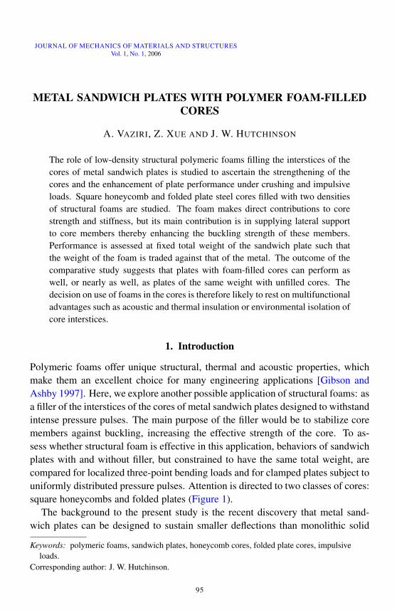
Polymeric foams offer unique structural, thermal and acoustic properties, whichmake them an excellent choice for many engineering applications [Gibson andAshby 1997]. Here, we explore another possible application of structural foams: asa filler of the interstices of the cores of metal sandwich plates designed to withstandintense pressure pulses. The main purpose of the filler would be to stabilize coremembers against buckling, increasing the effective strength of the core. To as-sess whether structural foam is effective in this application, behaviors of sandwichplates with and without filler, but constrained to have the same total weight, arecompared for localized three-point bending loads and for clamped plates subject touniformly distributed pressure pulses. Attention is directed to two classes of cores:square honeycombs and folded plates (Figure 1).
The background to the present study is the recent discovery that metal sand-wich plates can be designed to sustain smaller deflections than monolithic solid
Keywords: polymeric foams, sandwich plates, honeycomb cores, folded plate cores, impulsiveloads.
Corresponding author: J. W. Hutchinson.
95
96 A. VAZIRI, Z. XUE AND J. W. HUTCHINSON
(a) square honeycomb sandwich plate
(b) folded sandwich plate
Figure 1: Schematic diagram of sandwich plate core configuration and correspond-ing computation model of sandwich panel (the polymeric foam components are notshown)
METAL SANDWICH PLATES WITH POLYMER FOAM-FILLED CORES 97
plates of the same weight when subject to intense pressure pulses, particularlywhen the pulse is transmitted through water [Xue and Hutchinson 2003; Xue andHutchinson 2004a; Xue and Hutchinson 2004b; Hutchinson and Xue 2005]. Thecore plays a critical role in the performance of the sandwich plate: typically, itmust be able to absorb more than one half of the initial kinetic energy imparted tothe plate by crushing in the early stages of deformation prior to significant overallbending and stretching without unduly reducing the separation between the facesheets. High crushing strength and energy absorption per unit mass of the core istherefore important. Square honeycomb cores have been shown to be especiallyeffective [Xue and Hutchinson 2004a], and this is one of the core-types consideredhere. Folded plate cores are more susceptible to buckling under crushing thansquare honeycombs but are nevertheless effective, and they have manufacturingadvantages. In this paper, enhancement of the buckling resistance of the core websdue to lateral support of the foam will be investigated. The tradeoff against suchenhancement is the inevitable loss in bending and/or stretching strength accompa-nying the reduction in metal required to pay for the weight of the foam. The netgain or loss to the overall performance of the plate by incorporating the foam is byno means obvious when the total mass of the plate is constrained to be constant.
The paper begins with the specification of the sandwich plate geometries andmaterial properties in Section 2. The material comprising the sandwich plate coreand face sheet is stainless steel (#304). The foam material is a closed-cell PVCfoam material with the commercial name Divinycell. Two commercially availabledensities of this polymeric foam are considered, H100 and H200. Details of thecontinuum constitutive model of the polymeric foam materials are described inSection 2.1. The finite element modeling is described in Section 2.2. A limitedinvestigation of the response of the core to three basic stressing histories (crushing,shear and stretching) is conducted in Section 3 to provide insight into the effect offilling the core interstices with foam. Section 4 presents comparative results, withand without the foam, for wide sandwich plates clamped along opposite edgesand subject to a quasi-static load applied by an indenter. Corresponding resultsfor clamped plates subject to a uniformly distributed intense impulse are givenin Section 5. Limited results for the plastic energy dissipation history of eachcomponent of the empty and foam-filled sandwich plates under impulsive loadare presented in Section 6. Conclusions are drawn in Section 7, where topics forfurther research will also be noted.
2. Specification of sandwich plates and material properties
2.1. Sandwich plates. Infinite sandwich plates of width 2L that are clamped alongtheir edges are considered. Figure 1 shows the periodic units employed in the finite
98 A. VAZIRI, Z. XUE AND J. W. HUTCHINSON
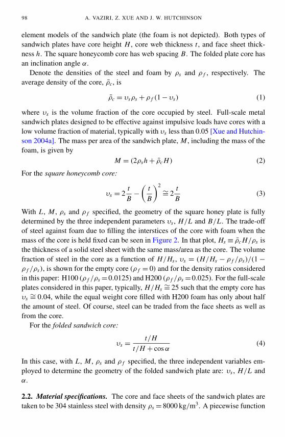
element models of the sandwich plate (the foam is not depicted). Both types ofsandwich plates have core height H , core web thickness t , and face sheet thick-ness h. The square honeycomb core has web spacing B. The folded plate core hasan inclination angle α.
Denote the densities of the steel and foam by ρs and ρ f , respectively. Theaverage density of the core, ρ̄c, is
ρ̄c = υsρs + ρ f (1 − υs) (1)
where υs is the volume fraction of the core occupied by steel. Full-scale metalsandwich plates designed to be effective against impulsive loads have cores with alow volume fraction of material, typically with υs less than 0.05 [Xue and Hutchin-son 2004a]. The mass per area of the sandwich plate, M , including the mass of thefoam, is given by
M = (2ρsh + ρ̄c H) (2)
For the square honeycomb core:
υs = 2tB
−
(tB
)2∼= 2
tB
(3)
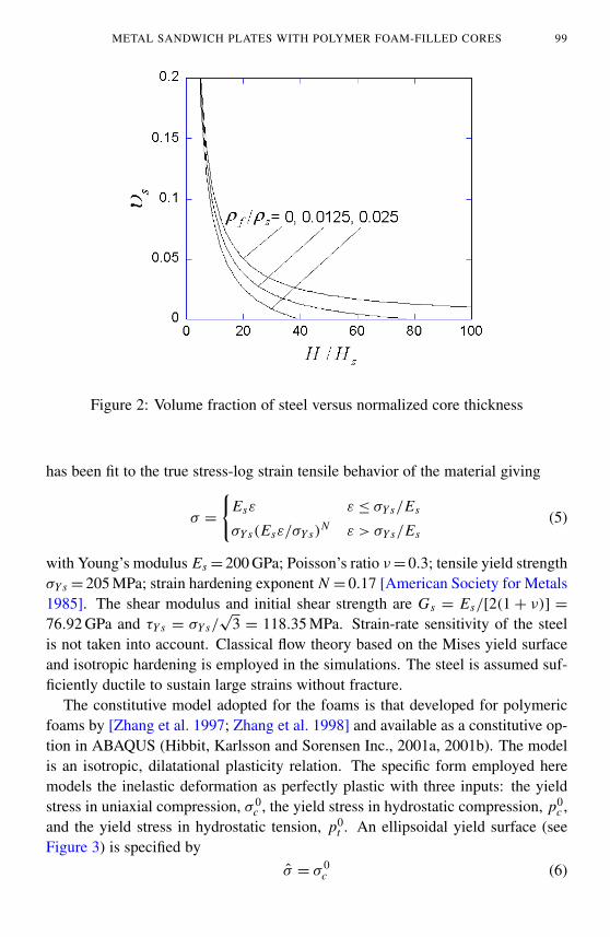
With L , M , ρs and ρ f specified, the geometry of the square honey plate is fullydetermined by the three independent parameters υs , H/L and B/L . The trade-offof steel against foam due to filling the interstices of the core with foam when themass of the core is held fixed can be seen in Figure 2. In that plot, Hs ≡ ρ̄c H/ρs isthe thickness of a solid steel sheet with the same mass/area as the core. The volumefraction of steel in the core as a function of H/Hs , υs = (H/Hs − ρ f /ρs)/(1 −
ρ f /ρs), is shown for the empty core (ρ f = 0) and for the density ratios consideredin this paper: H100 (ρ f /ρs =0.0125) and H200 (ρ f /ρs =0.025). For the full-scaleplates considered in this paper, typically, H/Hs ∼= 25 such that the empty core hasυs ∼= 0.04, while the equal weight core filled with H200 foam has only about halfthe amount of steel. Of course, steel can be traded from the face sheets as well asfrom the core.
For the folded sandwich core:
υs =t/H
t/H + cos α(4)
In this case, with L , M , ρs and ρ f specified, the three independent variables em-ployed to determine the geometry of the folded sandwich plate are: υs , H/L andα.
2.2. Material specifications. The core and face sheets of the sandwich plates aretaken to be 304 stainless steel with density ρs = 8000 kg/m3. A piecewise function
METAL SANDWICH PLATES WITH POLYMER FOAM-FILLED CORES 99
Figure 2: Volume fraction of steel versus normalized core thickness
has been fit to the true stress-log strain tensile behavior of the material giving
σ =
{Esε ε ≤ σY s/Es
σY s(Esε/σY s)N ε > σY s/Es
(5)
with Young’s modulus Es = 200 GPa; Poisson’s ratio ν = 0.3; tensile yield strengthσY s = 205 MPa; strain hardening exponent N = 0.17 [American Society for Metals1985]. The shear modulus and initial shear strength are Gs = Es/[2(1 + ν)] =
76.92 GPa and τY s = σY s/√
3 = 118.35 MPa. Strain-rate sensitivity of the steelis not taken into account. Classical flow theory based on the Mises yield surfaceand isotropic hardening is employed in the simulations. The steel is assumed suf-ficiently ductile to sustain large strains without fracture.
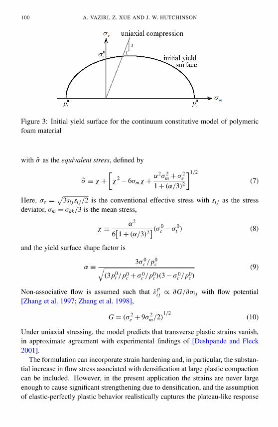
The constitutive model adopted for the foams is that developed for polymericfoams by [Zhang et al. 1997; Zhang et al. 1998] and available as a constitutive op-tion in ABAQUS (Hibbit, Karlsson and Sorensen Inc., 2001a, 2001b). The modelis an isotropic, dilatational plasticity relation. The specific form employed heremodels the inelastic deformation as perfectly plastic with three inputs: the yieldstress in uniaxial compression, σ 0
c , the yield stress in hydrostatic compression, p0c ,
and the yield stress in hydrostatic tension, p0t . An ellipsoidal yield surface (see
Figure 3) is specified byσ̂ = σ 0
c (6)
100 A. VAZIRI, Z. XUE AND J. W. HUTCHINSON
Figure 3: Initial yield surface for the continuum constitutive model of polymericfoam material
with σ̂ as the equivalent stress, defined by
σ̂ ≡ χ +
[χ2
− 6σmχ +α2σ 2
m + σ 2e
1 + (α/3)2
]1/2
(7)
Here, σe =√
3si j si j/2 is the conventional effective stress with si j as the stressdeviator, σm = σkk/3 is the mean stress,
χ ≡α2
6[1 + (α/3)2
](σ 0c − σ 0
t ) (8)
and the yield surface shape factor is
α ≡3σ 0
c /p0c√
(3p0t /p0
c + σ 0c /p0
c )(3 − σ 0c /p0
c )
(9)
Non-associative flow is assumed such that ε̇pi j ∝ ∂G/∂σi j with flow potential
[Zhang et al. 1997; Zhang et al. 1998],
G = (σ 2e + 9σ 2
m/2)1/2
(10)
Under uniaxial stressing, the model predicts that transverse plastic strains vanish,in approximate agreement with experimental findings of [Deshpande and Fleck2001].
The formulation can incorporate strain hardening and, in particular, the substan-tial increase in flow stress associated with densification at large plastic compactioncan be included. However, in the present application the strains are never largeenough to cause significant strengthening due to densification, and the assumptionof elastic-perfectly plastic behavior realistically captures the plateau-like response
METAL SANDWICH PLATES WITH POLYMER FOAM-FILLED CORES 101
Table 1: Mechanical properties of PVC polymeric foam
Foam Young’smodu-lus, E f
(MPa)
Poisson’sratio
Initial uniaxialcompressiveyield stress,σ 0
c (MPa)
Initialhydrostatic
compressiveyield stress, p0
c(MPa)
Hydrostatictensile yield
stress, p0t
(MPa)
H100 105 0.2 1.1 1.0 1.8H200 293 0.33 3.0 2.8 4.0
of the foam in the intermediate strain range. The formulation can also incorpo-rate strain-rate dependence of the foam. Tests [Deshpande and Fleck 2001] in therange of strain-rates from 10−3 s−1 to 10 s−1 reveal only a moderately weak ratedependence, which will be neglected in this first study.
Compression tests on the foam reveal some anisotropy with the yield strengthtypically about 20% higher in the rise direction of the foam than in transversedirections [Abot et al. 2002; Fleck and Sridhar 2002]. The isotropic model usedhere neglects this anisotropy; the uniaxial yield stress, σ 0
c , is associated with thedirection perpendicular to the rise direction. The parameters characterizing thefoam are presented in Table 1. The values for σ 0
c and Young’s modulus in Table 1are taken from data in [Deshpande and Fleck 2001] and [Fleck and Sridhar 2002]and are lower than the values suggested by the manufacturer of the polymeric foams[DIAB Inc. ≥ 2006].
2.3. Finite element model and specification of the plates. The finite element mod-els were developed using ABAQUS/CAE software. All components (face sheets,core webs and polymeric foam components) were fully meshed with three-dimensionalelements. Eight-node brick elements were employed with reduced integration. Theloading was taken to be independent of the coordinate in the long direction, andthus it was possible to analyze the three-dimensional unit of the plate that repeatsperiodically along its length as shown in Figure 1. Periodic boundary conditionswere applied at each end of the repeating unit in the long direction, symmetry aboutthe centerline was invoked, and clamped conditions were imposed along the twosides, corresponding to face sheets welded to rigid walls. Core webs were takenas welded to the face sheets. The commercial code, ABAQUS Explicit [Hibbitet al. 2001a], was utilized to perform most of the calculations, both dynamic andquasi-static.
Full-scale plates are considered in this paper whose half-width, L , is on the orderof a meter. Steel sandwich plates with empty, square honeycomb cores optimized
102 A. VAZIRI, Z. XUE AND J. W. HUTCHINSON
against intense impulsive loads to have the minimum weight typically have a nor-malized core thickness H/L ∼= 0.3 [Hutchinson and Xue 2005]. However, plateswith H/L = 0.1 perform almost as well as the thicker optimal plates, and, becausethinner cores are preferable in many applications, all the examples considered inthis paper have H/L = 0.1. These optimal and near-optimal full-scale plates typi-cally have between 1/5 and 1/3 of the their total mass in the core, correspondingto a volume fraction of core material in the range 0.02 < υs < 0.05. Several setsof calculations will be performed to explore the role of filling the core intersticeswith foam: (i) basic core responses to crush, shear and stretch; (ii) plate responseto quasi-static load; and (iii) plate response to impulsive load.
3. Responses of empty and foam-filled cores subject to basic loading histories
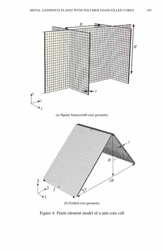
The unit cells corresponding to core geometries of square honeycomb and foldedplates are given in Figs. 4a and 4b, respectively, along with the coordinate sys-tem. To reveal the effect of filling the core interstices with foam, overall stress-strain curves of the core are computed using for three basic loading histories: corecompression, in-plane tension and out-of-plane shear. These are the three mostimportant loading histories for many applications.
The unit cells of Figure 4 are used in these finite element computations. In thecompression and shear loadings, rigid plates are bonded to top and bottom surfacesof the unit cell to simulate the behavior of the core attached to the face sheets. Thebottom plate is fixed and the top face is displaced. Periodicity is exploited, andperiodic boundary conditions are imposed on the unit cell consistent with eachloading. Thus, for example, in core compression of the square honeycomb theshear tractions on the web edges in Figure 4a are zero while the in-plane edge dis-placement parallel to the web is constrained to be zero, simulating overall uniaxialstraining as constrained by the faces. For shear loading, there is no net force inthe direction perpendicular to the faces. For the folded plate cell in Figure 4b, thelength, `, of the unit is a parameter that must be varied to determine the criticalbuckling mode. The loading referred to as in-plane tension is in reality overalltension subject to zero in-plane straining in the transverse direction consistent withstretching of the infinitely long plate clamped on its sides. For this loading, theedges of the web aligned with the direction of loading are displaced relative toone another uniformly while the edges of the transverse webs are constrained sothey undergo no in-plane displacement parallel to the web. Shear tractions vanishon all the edges, and zero traction on the top and bottom edges is enforced in thedirection perpendicular to the faces. Further details are described for the analogouscalculations for empty cores in [Xue and Hutchinson 2004b]. In the finite elementmodels of foam-filled cores, the displacements of the steel core and polymeric
METAL SANDWICH PLATES WITH POLYMER FOAM-FILLED CORES 103
(a) Square honeycomb core geometry
(b) Folded core geometry
Figure 4: Finite element model of a unit core cell
104 A. VAZIRI, Z. XUE AND J. W. HUTCHINSON
foam coincide at nodal points on shared interfaces. When analyzed with implicitmethods, the problems addressed in this paper have very low rates of convergence,because of the complexity of the geometry and the extreme variation of the materialbehavior. For this reason, ABAQUS Explicit [Hibbit et al. 2001a] is utilized tosimulate each simple stress history of empty and foam-filled cores. The analysesare performed under a sufficiently low rate of loading such that inertial effects arevery small and the response is essentially quasi-static. Further discussion on thistopic is presented in Section 4. The detailed analysis of the “micro” behavior of thecore accounts for finite rotations and large plastic strains and it captures featuressuch as plastic buckling and local necking of the core webs (square honeycomb)or core plate (folded sandwich).
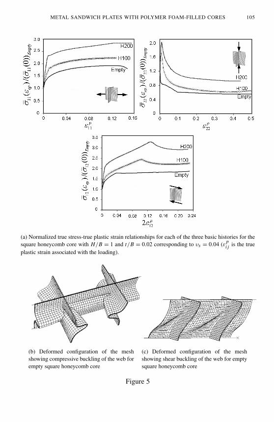
3.1. Square honeycomb core. The overall stress-strain responses for the three ba-sic loading histories are shown (Fig. 5) for a square honeycomb core with H/B = 1and t/B = 0.02, corresponding to a volume fraction of steel, υs = 0.04, whetherempty or filled. The foam constitutes additional mass in this plot. The dimensionsof the core are such that yielding occurs prior to elastic buckling, and plastic buck-ling is the source of nonlinear deformation for crushing and shearing. The stressesare defined as true stresses. The overall stresses, σ̄i j , are normalized by their initialyield values for the empty core given later. Because of its relevance to core crush,the compression history is determined to larger strains than in-plane tension andout-of-plane shear. Representative web buckling deflections are included in Figure5 for compression and shear.
Estimates of the elastic stiffness and initial yield strength of the core based onsimple strength of materials formulas are informative as to the role of the foam.For the square honeycomb, estimates of the overall elastic moduli associated withuniaxial stressing in the three directions of orthotropy and out-of-plane shearingare
E22 ≈ υs Es + (1 − υs)E f
E11 = E33 ≈12υs Es + (1 −
12υs)E f
G12 = G23 ≈12υs Gs + (1 −
12υs)G f
(11)
with no accounting for constraint from the faces. The associated average densityof the core, ρ̄c, is given by (1). For a typical core with υs = 0.04, filling with H100foam increases ρ̄c by 30%, E22 by 1%, and E22 and G12 by 2%. The correspondingincreases for H200 foam are roughly 60%, 3% and 6%. Obviously, the purpose offilling the core with foam is not to increase the overall elastic stiffness—employingthe additional mass, as steel would be far more effective.
The effect of filling the core with foam on plastic yielding of the core in theabsence of buckling is more significant than its effect on elastic stiffness. Two
METAL SANDWICH PLATES WITH POLYMER FOAM-FILLED CORES 105
(a) Normalized true stress-true plastic strain relationships for each of the three basic histories for thesquare honeycomb core with H/B = 1 and t/B = 0.02 corresponding to υs = 0.04 (ε p
i j is the trueplastic strain associated with the loading).
(b) Deformed configuration of the meshshowing compressive buckling of the web forempty square honeycomb core
(c) Deformed configuration of the meshshowing shear buckling of the web for emptysquare honeycomb core
Figure 5
106 A. VAZIRI, Z. XUE AND J. W. HUTCHINSON
sets of estimates are given of the overall yield stress for uniaxial stressing in thedirections of orthotropy (again with no constraint of the faces) and out-of-planeshearing: (i) the average stress at the strain when the steel yields and (ii) the averagestress at the strain when the foam yields1. In uniaxial stressing, the steel yields ata strain of 0.1%, while the foams yield at a strain of about 1%. At the strain thesteel yields:
σ̄22(0) ≈ υsσY s + (1 − υs)(σY s/Es)E f
σ̄11(0) = σ̄33(0) ≈12υsσY s + (1 −
12υs)(σY s/Es)E f
σ̄12(0) = σ̄23(0) ≈12υsτY s + (1 −
12υs)(τY s/Gs)G f
(12)
Adding foam only increases the initial yield stresses by a few percent. The effectof the foam on the stress at the strain that the foam yields is more significant:
σ̄22 ≈ υsσY s + (1 − υs)σY f
σ̄11 = σ̄33 ≈12υsσY s + (1 −
12υs)σY f
σ̄12 = σ̄23 ≈12υsτY s + (1 −
12υs)τY f
(13)
where the yield stresses of the foam are given in Table 1. Strictly, σY s and τY s
should be identified with the corresponding yield strains of the foam, but the in-crease in stress in the steel above its initial yield due strain hardening at strainson the order of 1% is not large. The elevation in σ̄22 due to the H100 foam isalmost 15% while that for the H200 foam is almost 40%. These increases are stillonly about half what would be achieved if extra mass were used to increase thesteel in the webs. However, for in-plane stressing and out-of-plane shearing, H100foam gives rise to an 30% increase in the overall yield stresses, while H200 foamincreases them by about 80%. These increases are comparable to what would beachieved by increasing the steel in the webs rather filling with foam.
The effects noted above are clearly evident in the overall stress-strain curvesin Figure 5. In these plots, each overall stress is normalized by the associatedinitial yield stress of empty core, σ̄i j (0)empty, given by (12). First, consider in-plane tension in Figure 5. The overall strain range plotted is too small for neckingto begin in the webs. The foam has almost no effect on first yield as expectedfrom the results quoted above. However, the overall stress increases sharply for
1As in the case of overall elastic stiffness, these are based on elementary estimates from thestrength of materials. They ignore, for example, lateral stresses that develop in uniaxial stressingdue to difference in the Poisson ratios of the steel and the foam. Nevertheless, the simplicity of theformulas nicely reveals the role of the foam, and the formulas are sufficiently accurate for presentpurposes.
METAL SANDWICH PLATES WITH POLYMER FOAM-FILLED CORES 107
strains less than about 1% due to the fact that the foam is still elastic. The abruptchange in slope at a strain of about 1% denotes the point where the foam yields;the associated stress is given approximately by (13). For even larger strains, theincreases in stress are due to strain hardening of the steel. The behavior in out-of-plane shear in Figure 5 is similar to that described for in-plane tension prior to webbuckling which causes the drop in overall stress. Addition of the foam significantlydelays the strain at which shear buckling occurs due to its constraint on the lateraldeflection of the webs. The consequent effect is the significant increase in theoverall flow strength of the core in shear. The foam also delays buckling of thewebs in the compressive loading in Figure 5, although buckling occurs at muchsmaller plastic strains in compression. (The dimensions of the empty core are suchthat plastic yielding and elastic buckling are almost coincident in compression.)In the post-buckling range, foam helps to stabilize the webs resulting in higheroverall stress. It remains to be seen in Section 4, whether the strengthening by thefoam observed in Figure 5 will persist when foam is added with a correspondingreduction in steel.
3.2. Folded plate core. The folded plate core has full orthotropic anisotropy. Inparticular, the in-plane stretching stiffness and strength of the empty core are sub-stantial in the 1-direction but negligible in the 3-direction. The core plate has coreheight H , core plate thickness t , and core inclination angle α. The width of theunit cell (Fig. 1b) is
B = t/ sin α + H/ tan α. (14)
The volume fraction of the core occupied by steel, υs , and the relative density ofthe core, ρ̄c, can be obtained from (4) and (1), respectively.
In the calculations, two core geometries are considered: (a) α = 45◦ with t/H =
0.0144, corresponding to B/H ≈ 1.021 and υs = 0.02, and (b) α = 45◦ witht/H = 0.0295, corresponding to B/H ≈ 1.042 and υs = 0.04. In out-of-planecompression with no foam, core (a) buckles elastically prior to yielding, whilecore (b) yields plastically prior to buckling.
Simple estimates for the overall elastic moduli are
E11 ≈ υs Es + (1 − υs)E f
E22 = υs Es sin4 α + (1 − υs)E f
E33 = (1 − υs)E f
G12 ≈ υs Gs sin2 α + (1 − υs)G f
G23 ≈14υs Es sin2 2α + (1 − υs)G f
G13 ≈12υs Gs sin 2α + (1 − υs)G f
(15)
108 A. VAZIRI, Z. XUE AND J. W. HUTCHINSON
Terms of relative order tc/Hc have been neglected. The overall stresses at whichthe steel yields (assuming no buckling of the webs) are,
σ̄11(0) ≈ σY s[υs + (1 − υs)E f /Es
]σ̄22(0) = σY s
[υs sin2 α + (1 − υs)E f /Es
]σ̄12(0) = τY s
[υs sin α + (1 − υs)G f /Gs
]σ̄23(0) = τY s
[υs sin 2α/2 + (1 − υs)G f /Gs
]σ̄13(0) = τY s
[υs cos α + (1 − υs)G f /Gs
](16)
The corresponding results for the overall stresses at the strain when the foam yieldsare
σ̄11 ≈ υsσY s + (1 − υs)σY f
σ̄22 = υs sin2 α σY s + (1 − υs)σY f
σ̄12 = υs sin α τY s + (1 − υs)τY f
σ̄23 = υs sin 2α τY s/2 + (1 − υs)τY f
σ̄13 = υs cos α τY s + (1 − υs)τY f
σ̄33 = (1 − υs)σY f
(17)
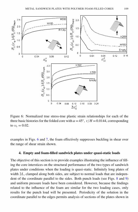
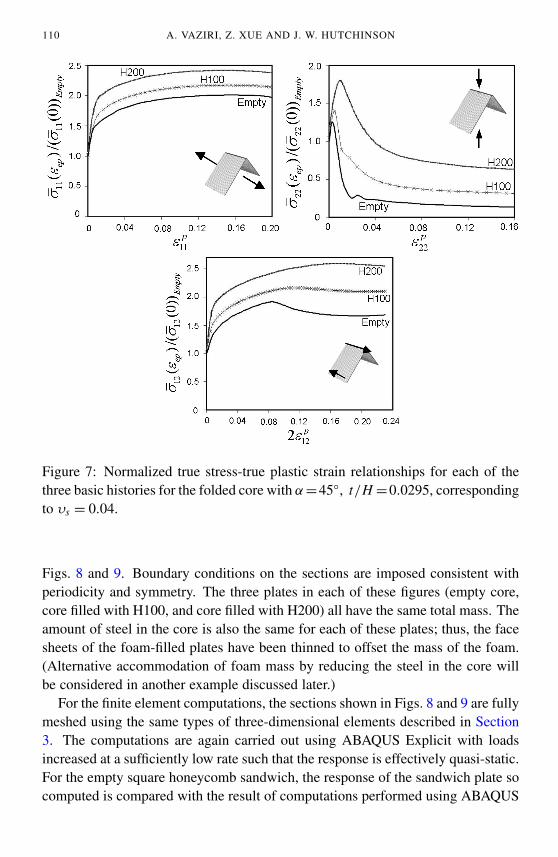
The basic stress histories for the folded plate core were computed by imposingperiodicity conditions on the segment ends. The overall stress-strain curves for thethree basic histories, each normalized by the associated initial yield stress of emptycore, σ̄i j (0)empty, are plotted in Figure 6 for the cores with υs = 0.02 and in Figure7 for υs = 0.04. The response for shear, σ̄12, subsequent to buckling depends onthe length of the segment, `; the curves presented in Figs. 6 and 7 have `/H = 1;this choice ensures that the overall shear at the onset of buckling is only slightlyabove the critical value.
The webs of the folded plate core with υs = 0.02 in Figure 6 are sufficiently thinsuch that elastic buckling occurs prior the plastic yielding of the empty steel coreunder compression σ̄22; plastic yielding then occurs immediately after the onsetof buckling causing the overall stress to fall dramatically. The role of the foamis substantially increasing the core strength at strains less than about 1%, priorto foam yield, is similar to that described for the square honeycomb core. Theeffect of the foam on the compressive behavior, σ̄22, of the core with more steel(υs = 0.04) in Figure 7 is qualitatively similar in most details. As expected, thestrengthening of the foam-filled core relative to the empty core is greatest for thecore with the lesser amount of steel.
The effect of the foam on the behaviors under in-plane tension and out-of-planeshear is in accord with the behavior of the square honeycomb cores. In the two
METAL SANDWICH PLATES WITH POLYMER FOAM-FILLED CORES 109
Figure 6: Normalized true stress-true plastic strain relationships for each of thethree basic histories for the folded core with α=45◦, t/H =0.0144, correspondingto υs = 0.02.
examples in Figs. 6 and 7, the foam effectively suppresses buckling in shear overthe range of shear strain shown.
4. Empty and foam-filled sandwich plates under quasi-static loads
The objective of this section is to provide examples illustrating the influence of fill-ing the core interstices on the structural performance of the two types of sandwichplates under conditions when the loading is quasi-static. Infinitely long plates ofwidth 2L , clamped along both sides, are subject to normal loads that are indepen-dent of the coordinate parallel to the sides. Both punch loads (see Figs. 8 and 9)and uniform pressure loads have been considered. However, because the findingsrelated to the influence of the foam are similar for the two loading cases, onlyresults for the punch load will be presented. Periodicity of the solution in thecoordinate parallel to the edges permits analysis of sections of the plates shown in
110 A. VAZIRI, Z. XUE AND J. W. HUTCHINSON
Figure 7: Normalized true stress-true plastic strain relationships for each of thethree basic histories for the folded core with α=45◦, t/H =0.0295, correspondingto υs = 0.04.
Figs. 8 and 9. Boundary conditions on the sections are imposed consistent withperiodicity and symmetry. The three plates in each of these figures (empty core,core filled with H100, and core filled with H200) all have the same total mass. Theamount of steel in the core is also the same for each of these plates; thus, the facesheets of the foam-filled plates have been thinned to offset the mass of the foam.(Alternative accommodation of foam mass by reducing the steel in the core willbe considered in another example discussed later.)
For the finite element computations, the sections shown in Figs. 8 and 9 are fullymeshed using the same types of three-dimensional elements described in Section3. The computations are again carried out using ABAQUS Explicit with loadsincreased at a sufficiently low rate such that the response is effectively quasi-static.For the empty square honeycomb sandwich, the response of the sandwich plate socomputed is compared with the result of computations performed using ABAQUS
METAL SANDWICH PLATES WITH POLYMER FOAM-FILLED CORES 111
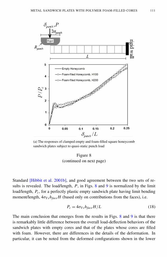
(a) The responses of clamped empty and foam-filled square honeycombsandwich plates subject to quasi-static punch load
Figure 8(continued on next page)
Standard [Hibbit et al. 2001b], and good agreement between the two sets of re-sults is revealed. The load/length, P , in Figs. 8 and 9 is normalized by the limitload/length, Pc, for a perfectly plastic empty sandwich plate having limit bendingmoment/length, 4σY shface H (based only on contributions from the faces), i.e.
Pc = 4σY shface H/L (18)
The main conclusion that emerges from the results in Figs. 8 and 9 is that thereis remarkably little difference between the overall load-deflection behaviors of thesandwich plates with empty cores and that of the plates whose cores are filledwith foam. However, there are differences in the details of the deformation. Inparticular, it can be noted from the deformed configurations shown in the lower
112 A. VAZIRI, Z. XUE AND J. W. HUTCHINSON
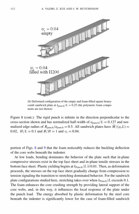
(b) Deformed configuration of the empty and foam-filled square honey-comb sandwich plate at δpunch/L = 0.25 (the polymeric foam compo-nents are not shown)
Figure 8 (cont.): The rigid punch is infinite in the direction perpendicular to thecross-section shown and has normalized half-width of apunch/L = 0.127 and nor-malized edge radius of Rpunch/apunch = 0.5. All sandwich plates have M̄/(ρs L) =
0.02, H/L = 0.1 and B/H = 1 and υs = 0.04.
portion of Figs. 8 and 9 that the foam noticeably reduces the buckling deflectionof the core webs beneath the indenter.
At low loads, bending dominates the behavior of the plate such that in-planecompressive stresses exist in the top face sheet and in-plane tensile stresses in thebottom face sheet. Plastic yielding begins at δPunch/L ∼=0.01. Then, as deformationproceeds, the stresses on the top face sheet gradually change from compression totension signaling the transition to stretching dominated behavior. For the sandwichplate configurations studied here, stretching takes over when δPunch/L exceeds 0.1.The foam enhances the core crushing strength by providing lateral support of thecore webs, and, in this way, it influences the local response of the plate underthe punch load. The energy absorbed by plastic deformation by the steel corebeneath the indenter is significantly lower for the case of foam-filled sandwich
METAL SANDWICH PLATES WITH POLYMER FOAM-FILLED CORES 113
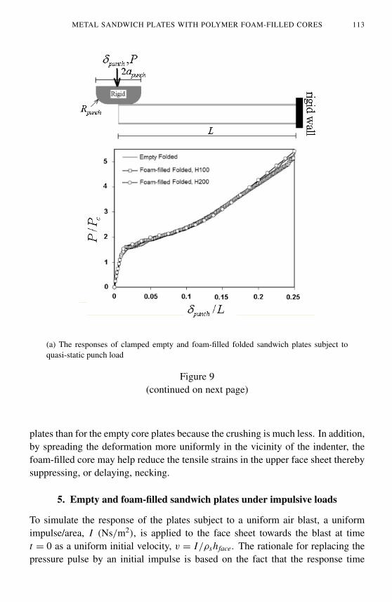
(a) The responses of clamped empty and foam-filled folded sandwich plates subject toquasi-static punch load
Figure 9(continued on next page)
plates than for the empty core plates because the crushing is much less. In addition,by spreading the deformation more uniformly in the vicinity of the indenter, thefoam-filled core may help reduce the tensile strains in the upper face sheet therebysuppressing, or delaying, necking.
5. Empty and foam-filled sandwich plates under impulsive loads
To simulate the response of the plates subject to a uniform air blast, a uniformimpulse/area, I (Ns/m2), is applied to the face sheet towards the blast at timet = 0 as a uniform initial velocity, v = I/ρshface. The rationale for replacing thepressure pulse by an initial impulse is based on the fact that the response time
114 A. VAZIRI, Z. XUE AND J. W. HUTCHINSON
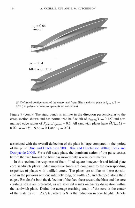
(b) Deformed configuration of the empty and foam-filled sandwich plate at δpunch/L =
0.25 (the polymeric foam components are not shown).
Figure 9 (cont.): The rigid punch is infinite in the direction perpendicular to thecross-section shown and has normalized half-width of apunch/L = 0.127 and nor-malized edge radius of Rpunch/apunch = 0.5. All sandwich plates have M̄/(ρs L) =
0.02, α = 45◦, H/L = 0.1 and υs = 0.04.
associated with the overall deflection of the plate is large compared to the periodof the pulse [Xue and Hutchinson 2003; Xue and Hutchinson 2004a; Fleck andDeshpande 2004]. For a full-scale plate, the dominant action of the pulse ceasesbefore the face toward the blast has moved only several centimeters.
In this section, the responses of foam-filled square honeycomb and folded platecore sandwich plates under impulsive loads are compared to the correspondingresponses of plates with unfilled cores. The plates are similar to those consid-ered in the previous section: infinitely long, of width 2L , and clamped along theiredges. Results for both the deflection of the face sheet toward the blast and the corecrushing strain are presented, as are selected results on energy dissipation withinthe sandwich plate. Define the average crushing strain of the core at the centerof the plate by ε̄c = 1H/H , where 1H is the reduction in core height. Denote
METAL SANDWICH PLATES WITH POLYMER FOAM-FILLED CORES 115
the final deflection at the center of the top face sheet by plate by δ. For the platewith the empty square honeycomb core, δ/L and ε̄c depend on the following setof dimensionless parameters [Xue and Hutchinson 2004a]:
IM
√σY s/ρs
,M
ρs L, υs,
HL
,BH
plus N and σY s/E . For plates with unfilled folded plate cores, normalized max-imum deflection and the crushing strain at the center depend on the same list ofdimensionless variables with the exception that B/H is replaced by α. In addition,dimensionless time variable governing the time-dependence is t
/(L/
√σY s/ρs
).
The computations were carried out using ABAQUS Explicit with the same periodicsections and three-dimensional meshes introduced for the quasi-static loadings.
The effect of the momentum impulse imparted to the top face sheet of the sand-wich plates, I
/(M
√σY s/ρs
), on δ/L and ε̄c are presented in Figs. 10 and 11.
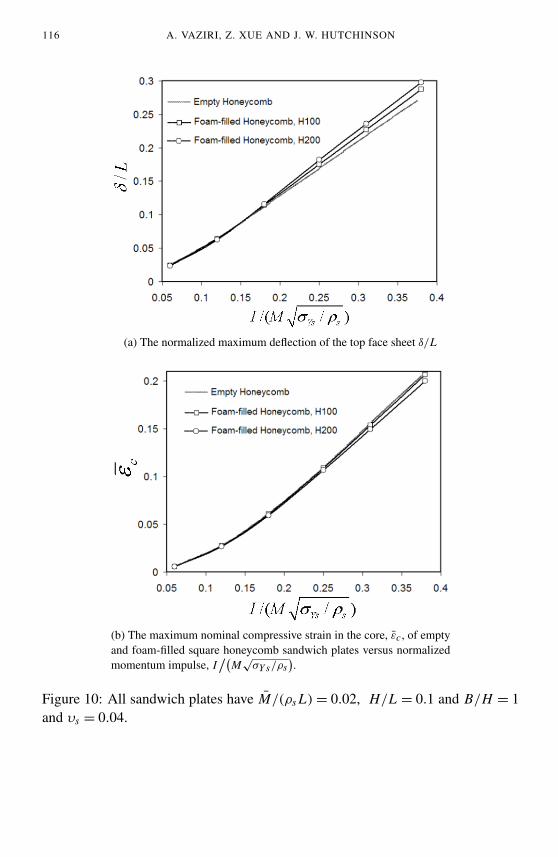
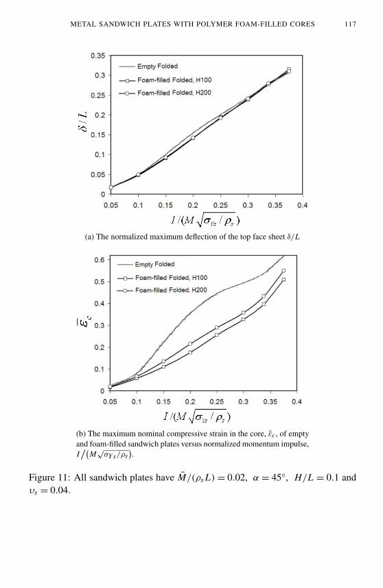
Results for empty cores and foam-filled cores are shown. The plates in these figuresall have the same total mass; foam mass is offset by thinning the face sheets, not thecore webs. All the sandwich plates have M/ρs L =0.02, υs =0.04, H/L =0.1. Forplates with honeycomb cores in Figure 10, B/H = 1, while for plates with foldedplate cores in Figure 11, α = 45◦. The range of normalized impulse plotted coversthe full range of realistic deflections. As was the case noted for the quasi-staticloadings, there is remarkably little difference in the maximum top face deflectionof the two classes of plates between the filled and unfilled cores. Foam reducesthe crushing strain of the folded plate core (Figure 11), but this does not translateinto a decrease in the overall deflection relative to the plate with the empty core.Inserting foam has little effect on the maximum crushing strain of plates with thesquare honeycomb cores. This is primarily due to the fact that the webs of the coreare stabilized against buckling by their lateral inertia at the high crushing velocitiesconsidered here [Vaughn et al. 2005].
In studying the comparative advantages of equal weight filled and unfilled plates,one would obviously want to know whether it is best to offset the weight of thefoam by thinning the face sheets or by thinning the core webs, or some combinationof the two. We have not carried out a thorough optimization addressing this issue,but we will present one set of computations for the sandwich plates with the squarehoneycomb cores that provides some insight into the question. The dimensions ofthe unfilled sandwich plate in Figure 10 were established to be nearly optimal ata normalized impulse level of I
/(M
√σY s/ρs
)= 0.25 by [Xue and Hutchinson
2004a]. In particular, the ratio of steel in the core to the total steel in the plate(20%) was found to minimize δ/L at that impulse level for all plates with the sametotal mass with B/H = 1 and H/L = 0.1. Moreover, the dependence on B/H andH/L was found to be relatively weak.
116 A. VAZIRI, Z. XUE AND J. W. HUTCHINSON
(a) The normalized maximum deflection of the top face sheet δ/L
(b) The maximum nominal compressive strain in the core, ε̄c, of emptyand foam-filled square honeycomb sandwich plates versus normalizedmomentum impulse, I
/(M
√σY s/ρs
).
Figure 10: All sandwich plates have M̄/(ρs L) = 0.02, H/L = 0.1 and B/H = 1and υs = 0.04.
METAL SANDWICH PLATES WITH POLYMER FOAM-FILLED CORES 117
(a) The normalized maximum deflection of the top face sheet δ/L
(b) The maximum nominal compressive strain in the core, ε̄c, of emptyand foam-filled sandwich plates versus normalized momentum impulse,I/(
M√
σY s/ρs).
Figure 11: All sandwich plates have M̄/(ρs L) = 0.02, α = 45◦, H/L = 0.1 andυs = 0.04.
118 A. VAZIRI, Z. XUE AND J. W. HUTCHINSON
For the sandwich plates with the square honeycomb cores subject to an impulse,I/(
M√
σY s/ρs)
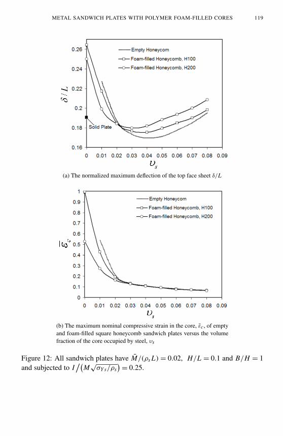
= 0.25, Figure 12 displays the dependence of the normalizedmaximum deflection, δ/L and the maximum core crushing strain on the volumefraction of steel in the core, υs , for unfilled cores and for cores filled with the twodensities of foam. The total mass/area of each plate is the same with M/ρs L =0.02;the deflection of the solid plate with the same mass/area and subject to the sameimpulse is included on the abscissa. Reducing νs increases the thickness of thefaces and vise versa, because the mass of foam in the core varies only slightlyover the range plotted of νs for each of the two foam-filled sandwiches. Thus,Figure 12 displays the tradeoff between core mass and face sheet mass. While theunfilled sandwich plate has the minimum deflection for cores with steel webs withrelative density υs = 0.04, the best performance from plates with foam-filled coresis achieved with lower relative density of steel—about 0.03 for the H200 foam.For plates with υs ≥ 0.02, the crushing strain is essentially the same for the filledand unfilled plates at the level of impulse imposed, and, moreover, it is less than20%.
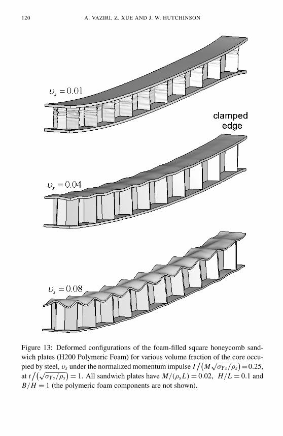
Figure 13 presents the final deformed configuration of the foam-filled squarehoneycomb sandwich plates (H200 Foam) for three volume fractions of the coreoccupied by steel, υs , under impulse, I
/(M̄
√σY s/ρs
)= 0.25. As in the previous
plots, all plates have M̄/(ρs L) = 0.02, H/L = 0.1 and B/H = 1. For a lowrelative density of steel in the core (υs = 0.01), local plastic buckling of the steelcore clearly compromises the performance of the plate such that the crushing strainis almost 30%. For plates with excess steel in the core (υs = 0.08) and thereforeoverly thinned face sheets, the top face undergoes extensive plastic bending into thecore while the core webs undergo very little deformation. The intermediate case(υs = 0.04) displays modest amounts of core deformation and face sheet bending.Note that for both υs = 0.04 and υs = 0.08, there is very little evidence of coreweb buckling, even though the core has been crushed to average strains of about12% and 7%, respectively. These crushing strains are far in excess of the strain atplastic yield (a small fraction of 1%) and, also, well above the quasi-static plasticbuckling strain of the webs. The suppression of buckling is due in part to the lateralsupport of the webs by the foam and the inertial stabilization of the webs under theimpulsive loading.
A limited study on the effect of foam densification on the structural performanceof square honeycomb sandwich plates filled with polymeric foam H200 under blastload is conducted by fitting a multi-linear line to the response of this material underuniaxial compressive load (see Section 2.2 for more detail). The sandwich plateshaving M̄/(ρs L) = 0.02, H/L = 0.1 and B/H = 1 with various volume fractionsof the core occupied by steel, 0 ≤ υs ≤ 0.04, are analyzed under the initial momen-tum I
/(M̄
√σY s/ρs
)= 0.25. The result shows that the deformation mechanism
METAL SANDWICH PLATES WITH POLYMER FOAM-FILLED CORES 119
(a) The normalized maximum deflection of the top face sheet δ/L
(b) The maximum nominal compressive strain in the core, ε̄c, of emptyand foam-filled square honeycomb sandwich plates versus the volumefraction of the core occupied by steel, υs
Figure 12: All sandwich plates have M̄/(ρs L) = 0.02, H/L = 0.1 and B/H = 1and subjected to I
/(M
√σY s/ρs
)= 0.25.
120 A. VAZIRI, Z. XUE AND J. W. HUTCHINSON
Figure 13: Deformed configurations of the foam-filled square honeycomb sand-wich plates (H200 Polymeric Foam) for various volume fraction of the core occu-pied by steel, υs under the normalized momentum impulse I
/(M
√σY s/ρs
)=0.25,
at t/(√
σY s/ρs)= 1. All sandwich plates have M/(ρs L) = 0.02, H/L = 0.1 and
B/H = 1 (the polymeric foam components are not shown).
METAL SANDWICH PLATES WITH POLYMER FOAM-FILLED CORES 121
of the foam-filled square honeycomb sandwich plates is not significantly affectedby considering the foam densification behavior under uniaxial compression. Themaximum effect of accounting for foam densification on the maximum displace-ment of the top face sheet and maximum nominal compressive strain in the coreare ≈ 1.1% and ≈ 6.5%, respectively.
6. Plastic energy absorption in foam-filled honeycomb sandwich plates
Insight into the role of the polymer foam is gained by examining the contributionsto plastic energy dissipation of each component of the empty and foam-filled (H200foam) sandwich plates under impulsive load. Figure 14 displays the time historyof the plastic dissipation in the core and face sheets along with the total plasticdissipation for the two plates, each of which has M/ρs L = 0.02, υs = 0.04,H/L = 0.1, B/H = 1 and subject to I
/(M̄
√σY s/ρs
)= 0.25. The results are
plotted in dimensionless form as UP/K E0, where K E0 is the initial kinetic energyimparted to the plate and UP is the energy dissipated in plastic deformation in thecomponent indicated at time t
/(L/
√σY s/ρs
). The total dissipation is also shown.
For a prescribed initial momentum impulse applied to the top face sheet, I , theinitial kinetic energies imparted to the plate is K E0 = I 2/(2ρshface). Thus, thefoam-filled plate has to absorb more energy than the unfilled plate since in theexample in Figure 14 the face sheets of the filled plate are thinner than those ofthe unfilled plate (the total mass and the mass of steel in each core is the same forthe two plates). The results in Figure 14 show that for both sandwich plates, theearliest stage of deformation with t
/(L/
√σY s/ρs
)< 0.05 (Stage II, [Fleck and
Deshpande 2004]) consists of the top face sheet flying into, and crushing the core.In this stage, the motion away from the clamped supports is one-dimensional, thebottom face sheet is almost stationary, and very little plastic dissipation occurs inthe bottom face sheets. By the end of this stage, the two face sheets are movingwith nearly the same velocity. In this stage, the foam contributes significantly to theplastic energy dissipation of the foam-filled sandwich plate core layer by absorbingaround 10% of the initial kinetic energy. As a consequence, the energy dissipatedin the steel core of the foam-filled sandwich plate is around 10% smaller than thatthe empty sandwich one. The total plastic energy dissipated in the sandwich platein stage II is almost the same for both cases (≈ 60%), in close agreement with thesimple analysis based on the conservation of momentum between the beginningand end of stage II [Fleck and Deshpande 2004].
Subsequent to stage II, there is essentially no further core compression and theentire sandwich plate undergoes bending followed by in-plane stretching (stage IIIof [Fleck and Deshpande 2004]. In this stage, the kinetic energy not absorbed in
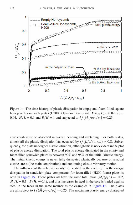
122 A. VAZIRI, Z. XUE AND J. W. HUTCHINSON
Figure 14: The time history of plastic dissipation in empty and foam-filled squarehoneycomb sandwich plates (H200 Polymeric Foam) with M/(ρs L) = 0.02, υs =
0.04, H/L = 0.1 and B/H = 1 and subjected to I/(
M√
σY s/ρs)= 0.25.
core crush must be absorbed in overall bending and stretching. For both plates,almost all the plastic dissipation has occurred by t
/(L/
√σY s/ρs
)≈ 0.8. Subse-
quently, the plate undergoes elastic vibration, although this is not evident in the plotof plastic energy dissipation. The total plastic energy dissipated in the empty andfoam-filled sandwich plates is between 90% and 95% of the initial kinetic energy.The initial kinetic energy is never fully dissipated plastically because of residualelastic stress (the main contribution) and continuing elastic vibratory motion.
The influence of the relative density of the steel in the core, υs , on the energydissipation in sandwich plate components for foam-filled (H200 foam) plates isseen in Figure 15. These plates all have the same total mass (M̄/(ρs L) = 0.02,Hc/L = 0.1, B/Hc = 0.1), and thus increases in steel in the core is traded againststeel in the faces in the same manner as the examples in Figure 12. The platesare all subject to I
/(M̄
√σY s/ρs
)= 0.25. The maximum plastic energy dissipated
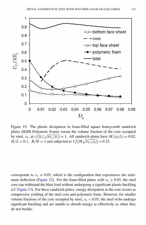
METAL SANDWICH PLATES WITH POLYMER FOAM-FILLED CORES 123
Figure 15: The plastic dissipation in foam-filled square honeycomb sandwichplates (H200 Polymeric Foam) versus the volume fraction of the core occupiedby steel, υs , at t
/(L/
√σY s/ρs
)= 1. All sandwich plates have M/(ρs L) = 0.02,
H/L = 0.1, B/H = 1 and subjected to I/(
M√
σY s/ρs)= 0.25.
corresponds to υs = 0.03, which is the configuration that experiences the mini-mum deflection (Figure 12). For the foam-filled plates with υs ≥ 0.03, the steelcore can withstand the blast load without undergoing a significant plastic buckling(cf. Figure 13). For these sandwich plates, energy dissipation in the core occurs ascompressive yielding of the steel core and polymeric foam. However, for smallervolume fractions of the core occupied by steel, υs < 0.03, the steel webs undergosignificant buckling and are unable to absorb energy as effectively as when theydo not buckle.
124 A. VAZIRI, Z. XUE AND J. W. HUTCHINSON
7. Concluding remarks
The examples presented in this paper indicate that sandwich plates with foam-filledsquare honeycomb cores and folded plate cores exhibit comparable structural per-formance in resisting deformation to sandwich plates of equal mass with unfilledcores under representative quasi-static and impulsive loads. In other words, whilethere appears to be no clear advantage to filling the core with foam for structuralpurposes, there is no evident disadvantage either. Thus, if other compelling reasonsto fill core interstices with foam exist, such as environmental protection or sound-proofing, the examples here suggest that it should be possible to do this withoutstructural penalty. These conclusions are drawn from the examples in the presentstudy that have been limited to cores with thickness fixed relative to the half-widthof the plate at H/L = 0.1. Earlier work has shown that this core thickness isassociated with plates with near-optimal structural performance against uniformlydistributed air and water blasts, although thicker cores can be somewhat more ef-fective. Sandwich plates with foam-filled, thicker cores will have larger fractionof their total mass in foam, and it is not obvious that they will retain the structuralperformance of their unfilled counter parts. Thus, we emphasize that further studyis required if sandwich plates have thickness significantly larger than H/L = 0.1.
Acknowledgement
This work has been supported in part by the ONR under grants GG10376-114934and N00014–02–1–0700 and in part by the Division of Engineering and AppliedSciences, Harvard University.
References
[Abot et al. 2002] J. L. Abot, I. M. Daniel, and E. E. Gdoutos, “Contact Law for Composite Sand-wich Beams”, Journal of Sandwich Structures and Materials 4 (2002), 157–173.
[American Society for Metals 1985] B. H. E. and T. L. Gall (editors), Metals Handbook Desk Edi-tion, American Society for Metals, 1985.
[Deshpande and Fleck 2001] V. S. Deshpande and N. A. Fleck, “Multi-Axial Yield Behavior ofPolymer Foams”, Acta Materialia 49 (2001), 1859–1866.
[DIAB Inc. ≥ 2006] DIAB Inc., “Divinycell Technical Manual, H Grade”.
[Fleck and Deshpande 2004] N. A. Fleck and V. S. Deshpande, “Blast resistance of clamped sand-wich beams”, 2004. Submitted for publication to the Journal of Applied Mechanics.
[Fleck and Sridhar 2002] N. A. Fleck and I. Sridhar, “End Compression of Sandwich Columns”,Composites: Part A 33 (2002), 353–359.
[Gibson and Ashby 1997] L. J. Gibson and M. F. Ashby, Cellular Solids: Structures and properties,Second ed., Cambridge University Press, Cambridge, 1997.
[Hibbit et al. 2001a] Hibbit, Karlsson, and Sorensen Inc., ABAQUS/Explicit User’s Manual, Version6.0, 2001.
METAL SANDWICH PLATES WITH POLYMER FOAM-FILLED CORES 125
[Hibbit et al. 2001b] Hibbit, Karlsson, and Sorensen Inc., ABAQUS/Standard User’s Manual, Ver-sion 6.0, 2001.
[Hutchinson and Xue 2005] J. W. Hutchinson and Z. Xue, “Metal sandwich plates optimized forpressure impulses”, Int. J. Mech. Sci. (2005). Article in press.
[Vaughn et al. 2005] D. Vaughn, M. Canning, and J. W. Hutchinson, “Coupled plastic wave propa-gation and column buckling”, J. Appl. Mech. 72 (2005), 1–8.
[Xue and Hutchinson 2003] Z. Xue and J. W. Hutchinson, “Preliminary assessment of sandwichplates subject to blast loads”, Int. J. Mech. Sci. 45 (2003), 687–705.
[Xue and Hutchinson 2004a] Z. Xue and J. W. Hutchinson, “A Comparative study of blast-resistantmetal sandwich plates”, Int. J. Impact Engineering 30 (2004), 1283–1305.
[Xue and Hutchinson 2004b] Z. Xue and J. W. Hutchinson, “Constitutive model for quasi-staticdeformation of metallic sandwich cores”, Int. J. Numerical Methods in Engineering 61 (2004),2205–2238.
[Zhang et al. 1997] J. Zhang, Z. Lin, A. Wong, N. Kikuchi, V. C. Li, A. F. Yee, and G. S. Nusholtz,“Constitutive Modeling and Material Characterization of Polymeric Foam”, Journal of EngineeringMaterials and Technology 119 (1997), 284–291.
[Zhang et al. 1998] J. Zhang, N. Kikuchi, V. C. Li, A. F. Yee, and G. S. Nusholtz, “ConstitutiveModeling of Polymeric Foam Material Subjected to Dynamic Crash Loading”, Int. J. Impact Engng.21 (1998), 369–386.
Received 9 May 05. Revised 7 Sep 05.
A. VAZIRI: Division of Engineering and Applied Sciences, Harvard University, Cambridge [email protected]
Z. XUE: Division of Engineering and Applied Sciences, Harvard University, Cambridge MA02138
J. W. HUTCHINSON: [email protected] of Engineering and Applied Sciences, Harvard University, Cambridge MA 02138


![Forming of Sandwich Sheets Considering Changing Damping ... · Forming of Sandwich Sheets Considering Changing Damping Properties 87 stiffnesses with thick synthetic cores. [10] As](https://img.pdfslide.net/doc/110x75/5e847f5fb32bfb26870b4028/forming-of-sandwich-sheets-considering-changing-damping-forming-of-sandwich.jpg)