Embed Size (px)
Citation preview
Solutions for Materials Preparation, Testing and Analysis
By: George Vander Voort
Metallographic Preparation of Titanium and its Alloys
Published by Buehler, a division of Illinois Tool Works Volume 3, Issue 3
Titanium and its alloys have become very important commercially over the past fifty years due to their low density, good strength-to-weight ratio, excellent corrosion resistance and good mechanical properties. On the negative side, the alloys are expensive to produce. Titanium, like iron, is allotropic and this produces many heat treatment similarities with steels. Moreover, the influences of alloying elements are assessed in like manner regarding their ability to stabilize either the low temperature phase, alpha, or the high temperature phase, beta. Like steels, Ti and its alloys are generally characterized by their stable room temperature phases - alpha alloys, alpha-beta alloys and beta alloys, but with two additional categories: near alpha and near beta.
Titanium and its alloys are more difficult to prepare for metallographic examination than steels. They have much lower grinding and polishing rates. Deformation twinning can be induced in alpha alloys by overly aggressive sectioning and grinding procedures. It is safest to mount relatively pure Ti specimens in castable (“cold”) resins rather than using hot compression mounting due to the potential for altering the hydride content and morphology. Elimination of smearing and scratches during preparation can be quite difficult, especially for pure Ti.
Early mechanical preparation procedures [1-5] tended to be rather long, involved processes nearly always incorporating an attack polishing solution in the last step or last two steps. Some of the more commonly used attack polishing solutions are summarized in [6]. The problem of obtaining well prepared surfaces has prompted considerable interest in electropolishing procedures [3-5, 7, 8]. The inherent danger of some of these electrolytes has fostered interest in chemical polishing procedures [9]. Electrolytic and chemical polishing solutions for Ti and Ti alloys are also summarized in [6].
Mechanical polishing methods for titanium and its alloys continued to rely upon these older procedures into the 1970’s [10] and 1980’s [11]. Perhaps the first publication of a modern approach to preparing titanium was that of Springer and Ahmed [12] in 1984.
This was a three-step procedure, assuming that the planar grinding step can be performed with 320 grit SiC paper, which may not always be possible. If the specimens are sectioned using a wafering blade or an abrasive blade of the proper bond strength, that produces a smooth surface with minimal damage, then 320 grit SiC paper may be used. If a rougher surface with greater damage is produced, such as would result from use of a power hacksaw,
then grinding must commence with a coarser grit paper in order to remove the damage in a reasonable time.
The procedure developed by Springer and Ahmed was:1. Wet grind with 320 grit SiC paper for 2-3 minutes to obtain a
flat surface free of cutting damage.2. Rough polish with 9μm METADI® diamond paste on a
perforated TEXMET® cloth for 10-15 minutes with distilled water as lubricant.
3. Final polish with MASTERMET® colloidal silica suspension on either a MICROCLOTH® or a MASTERTEX® cloth for 10-15 minutes.
Unfortunately, they gave no guidelines as to the applied force and rotational speed or directions for each step.
G. Müller [13] also developed a three-step procedure for titanium. Again, it will take three steps only if sectioning produces a smooth surface with minimal damage. His procedure, for six 30mm (1.25 inch) diameter specimens in a holder, was:
1. Wet grind with P500 SiC paper, 300 rpm, 16.7N (3.75 lb.) load/specimens, until all surfaces are co-planar.
2. Wet grind with P1200 SiC paper, 300 rpm, 16.7N (3.75 lb.) load/specimen, for 30 seconds.
3. Polish with colloidal silica suspension containing an attack polishing agent on a synthetic napless cloth, 150 rpm, for: 10 minutes at 33N (7.5 lb.), 2 minutes at 16.7N (3.75 lb.), 2 minutes at 8N (2 lb.) load/ specimen, and 1 minute without any load.
The polishing suspension consisted of 260mL of colloidal silica, 40mL H2O2 (30%), 1mL HNO3 and 0.5mL HF. P500 and P1200 FEPA grits are equivalent to 320/360 and 600 grit sizes, respectively, in the ANSI/CAMI grading scale.
Preparation ExperimentsMethod of Springer and AhmedThe initial preparation experiments centered on evaluating, expanding and updating the method of Christa Springer and Wase Ahmed [12], “S&A”. As that specific type of perforated TEXMET cloth is no longer available, other surfaces had to be substituted and evaluated. Also, the published method did not specify the applied load, platen rpm or rotational directions.
The first experiment with the S&A method used:1. Grind with 320 grit SiC paper, water cooled, 240 rpm,
Visit our website at www.buehler.com for more information.
complementary* rotation, 27N (6 lbs.) load/specimen, until plane.
2. Rough polish with 9μm METADI diamond on an ULTRA-PAD™ cloth, 120 rpm, 27N (6 lbs.) load/specimen, METADI Fluid, contra** rotation, 10 minutes.
3. Final polish with MASTERMET 2 colloidal silica on a MICROCLOTH pad, 120 rpm, contra rotation, 27N (6 lbs.) load/specimen, 10 minutes.
*In complementary rotation, the head and platen rotate in the same direction.**In contra rotation, the head and platen rotate in opposite directions.
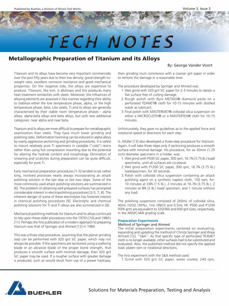
Results for titanium alloys were generally acceptable, although some scratches were observed; but, they were inadequate for CP titanium, as shown in Figure 1.
Addition of a 3μm diamond step between steps 2 and 3 did not improve the alpha alloy and the CP Ti microstructures. Whether the cloth used was hard and napless, or softer and napped, the results were the same for the CP Ti specimens. The use of an ULTRA-POL™ silk cloth in step 2 resulted in less scratches after this step and yielded acceptable results for the CP Ti specimens. A TEXMET 1000 pad was also tried for step 2 and found to produce nearly as good results as with the ULTRA-POL cloth. Figure 2 shows the results of three successive experiments where the surface of the same specimen was ground with 320 grit SiC (step 1) and then rough polished with 9μm diamond (step 2) on ULTRA-PAD™, ULTRA-POL and TEXMET 1000 cloths. Based on these experiments, ULTRA-POL was selected as the preferred cloth for step 2 and TEXMET 1000 pads were considered to be nearly equivalent.
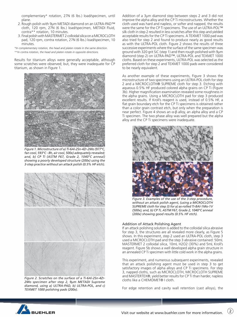
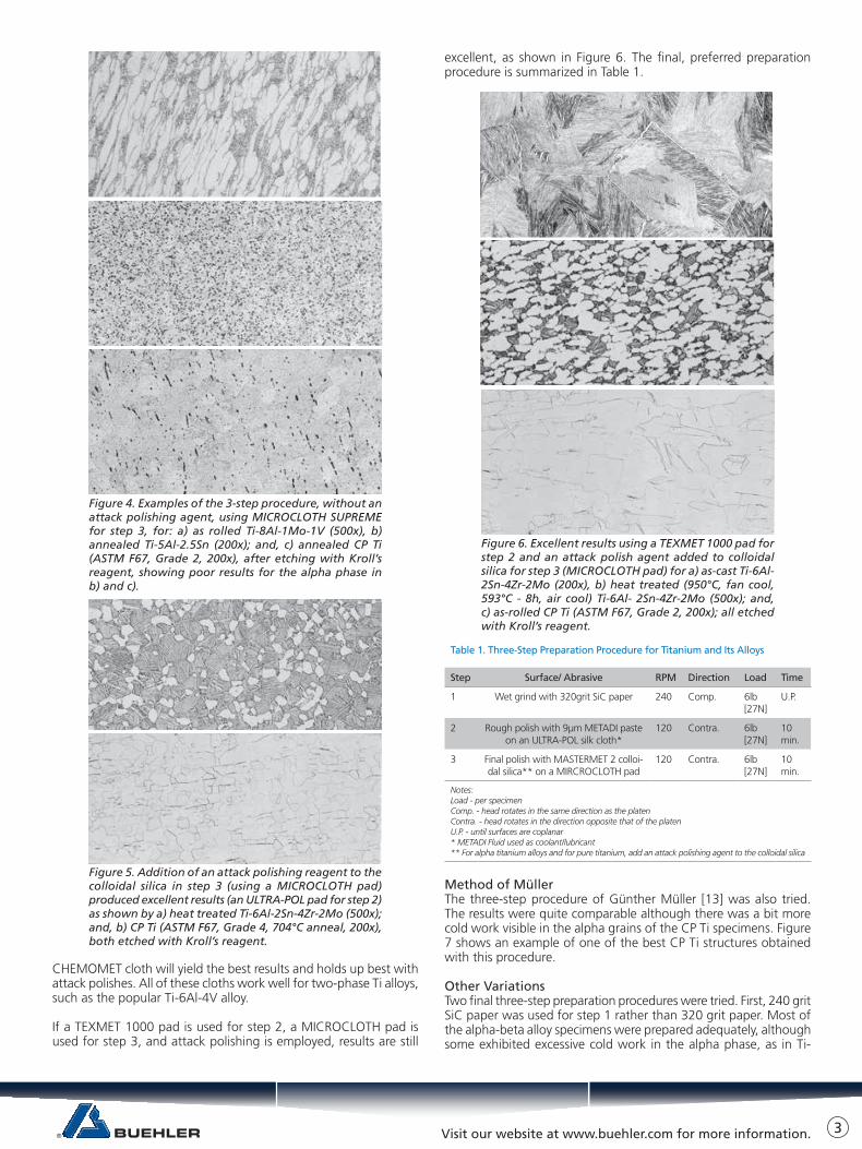
As another example of these experiments, Figure 3 shows the microstructure of two specimens using an ULTRA-POL cloth for step 2 and a MICROCLOTH® SUPREME cloth for step 3. Etching with aqueous 0.5% HF produced colored alpha grains on CP Ti (Figure 3b). Higher magnification examination revealed some roughness in the alpha grains. Using a MICROCLOTH pad for step 3 produced excellent results. If Kroll’s reagent is used, instead of 0.5% HF, a flat grain boundary etch for the CP Ti specimens is obtained rather than a color grain contrast etch, but only when the preparation is near perfect. Figure 4 shows an α-β alloy, an alpha alloy and a CP Ti specimen. The two phase alloy was well prepared but the alpha alloy and the CP Ti specimens were inadequate.
Addition of Attack Polishing AgentIf an attack polishing solution is added to the colloidal silica abrasive for step 3, the structures are all revealed more clearly, as Figure 5 shows. In this experiment, step 2 used an ULTRA-POL cloth, step 3 used a MICROCLOTH pad and the step 3 abrasive contained: 50mL MASTERMET 2 colloidal silica, 10mL H2O2 (30%) and 5mL Kroll’s reagent. Figure 5b shows a well developed alpha grain structure in an annealed CP Ti specimen with little cold work in the alpha grains.
This experiment, and numerous subsequent experiments, revealed that an attack polishing agent must be used in step 3 to get satisfactory images of alpha alloys and CP Ti specimens. For step 3, napped cloths, such as MICROCLOTH, MICROCLOTH SUPREME and MASTERTEX®, yield better results for CP Ti than harder, napless cloths like a CHEMOMET® I cloth.
For edge retention and cavity wall retention (cast alloys), the
Figure 1. Microstructure of a) Ti-6Al-2Sn-4Zr-2Mo (977°C, fan cool, 593°C - 8h, air cool, 500x) adequately revealed; and, b) CP Ti (ASTM F67, Grade 2, 1040°C anneal) showing a poorly developed structure (200x) using the 3-step practice without an attack polish (0.5% HF etch).
Figure 2. Scratches on the surface of a Ti-6Al-2Sn-4Zr-2Mo specimen after step 2, 9μm METADI Supreme diamond, using a) ULTRA-PAD, b) ULTRA-POL, and c) TEXMET 1000 polishing pads (200x).
Figure 3. Examples of the use of the 3-step procedure, without an attack polish agent, (using a MICROCLOTH SUPREME cloth for step 3) for a) as-rolled Ti-8Al-1Mo-1V (500x); and, b) CP Ti, ASTM F67, Grade 2, 1040°C anneal (200x) showing good results (0.5% HF etch).
2
Visit our website at www.buehler.com for more information.
CHEMOMET cloth will yield the best results and holds up best with attack polishes. All of these cloths work well for two-phase Ti alloys, such as the popular Ti-6Al-4V alloy.
If a TEXMET 1000 pad is used for step 2, a MICROCLOTH pad is used for step 3, and attack polishing is employed, results are still
excellent, as shown in Figure 6. The final, preferred preparation procedure is summarized in Table 1.
Method of MüllerThe three-step procedure of Günther Müller [13] was also tried. The results were quite comparable although there was a bit more cold work visible in the alpha grains of the CP Ti specimens. Figure 7 shows an example of one of the best CP Ti structures obtained with this procedure.
Other VariationsTwo final three-step preparation procedures were tried. First, 240 grit SiC paper was used for step 1 rather than 320 grit paper. Most of the alpha-beta alloy specimens were prepared adequately, although some exhibited excessive cold work in the alpha phase, as in Ti-
Figure 4. Examples of the 3-step procedure, without an attack polishing agent, using MICROCLOTH SUPREME for step 3, for: a) as rolled Ti-8Al-1Mo-1V (500x), b) annealed Ti-5Al-2.5Sn (200x); and, c) annealed CP Ti (ASTM F67, Grade 2, 200x), after etching with Kroll’s reagent, showing poor results for the alpha phase in b) and c).
Figure 5. Addition of an attack polishing reagent to thecolloidal silica in step 3 (using a MICROCLOTH pad) produced excellent results (an ULTRA-POL pad for step 2) as shown by a) heat treated Ti-6Al-2Sn-4Zr-2Mo (500x); and, b) CP Ti (ASTM F67, Grade 4, 704°C anneal, 200x), both etched with Kroll’s reagent.
Figure 6. Excellent results using a TEXMET 1000 pad for step 2 and an attack polish agent added to colloidal silica for step 3 (MICROCLOTH pad) for a) as-cast Ti-6Al-2Sn-4Zr-2Mo (200x), b) heat treated (950°C, fan cool, 593°C - 8h, air cool) Ti-6Al- 2Sn-4Zr-2Mo (500x); and, c) as-rolled CP Ti (ASTM F67, Grade 2, 200x); all etched with Kroll’s reagent.
Table 1. Three-Step Preparation Procedure for Titanium and Its Alloys
Step Surface/ Abrasive RPM Direction Load Time
1 Wet grind with 320grit SiC paper 240 Comp. 6lb [27N]
U.P.
2 Rough polish with 9μm METADI paste on an ULTRA-POL silk cloth*
120 Contra. 6lb [27N]
10 min.
3 Final polish with MASTERMET 2 colloi-dal silica** on a MIRCROCLOTH pad
120 Contra. 6lb [27N]
10 min.
Notes:Load - per specimenComp. - head rotates in the same direction as the platenContra. - head rotates in the direction opposite that of the platenU.P. - until surfaces are coplanar* METADI Fluid used as coolant/lubricant** For alpha titanium alloys and for pure titanium, add an attack polishing agent to the colloidal silica
3
Visit our website at www.buehler.com for more information.
6Al-4V containing equiaxed alpha. The alpha alloy and alpha CP Ti specimen microstructures exhibited substantial cold work. The other experiment involved substitutions of 0.05μm gamma alumina for colloidal silica in step 3 (using the same attack polishing additive). Results were generally acceptable, especially for the two-phase alloys, but the alpha phase in CP Ti specimens contained substantial cold work, Figure 8.
A few variants of the attack polishing solution were tried. Leonhardt [14] uses a mixture of: 150mL colloidal silica, 150mL water, 30mL H2O2 (30%), 1-5mL HF and 1-5mL HNO3. Results with this attack polishing additive to the abrasive were good and equivalent to the one used. Buchheit [6] added 5mL of a 20% aqueous CrO3 solution to 30mL of an alumina slurry. To try this, but using collidol silica instead, 10mL of the 20% CrO3 solution was added to 75mL of colloidal silica. This also produced excellent results. In using these attack polishing solutions, care must be taken in handling, mixing and using these additives as they contain very strong oxidizers and acids. Avoid physical contact with the ingredients and the prepared attack polishing abrasives.
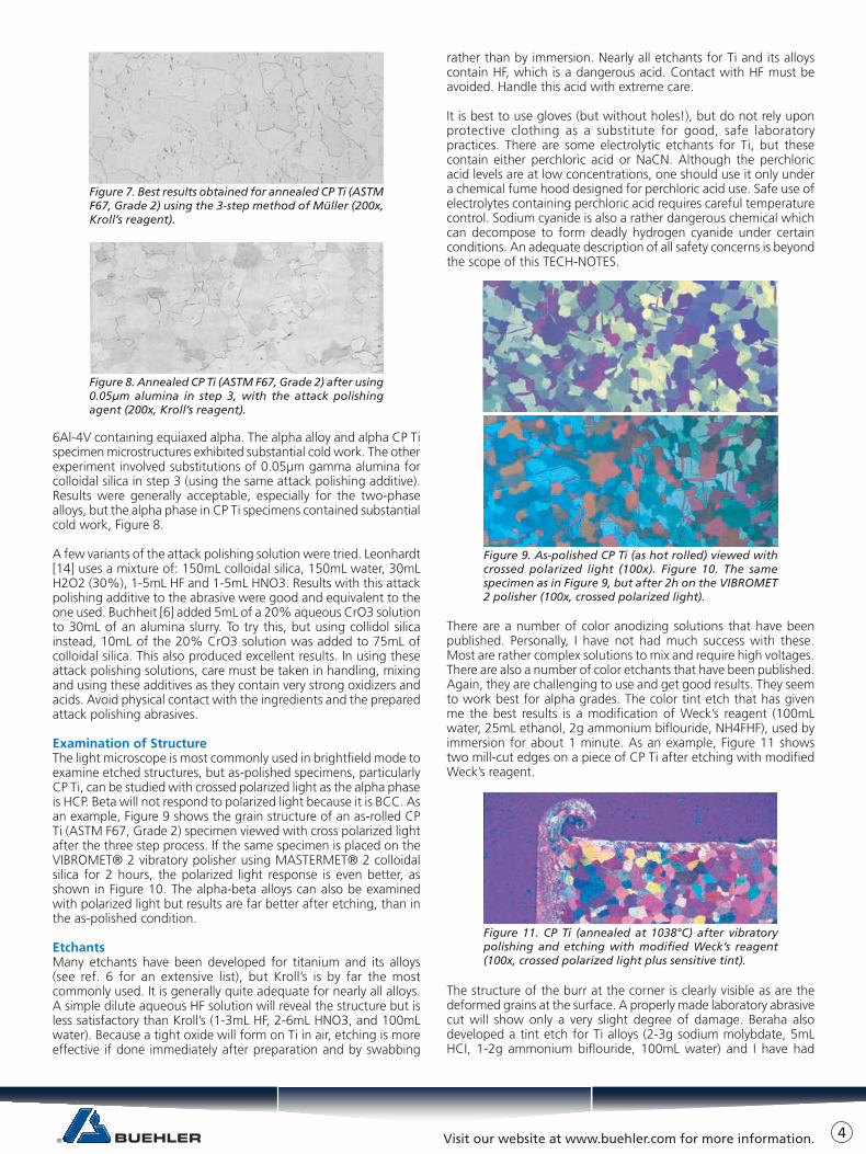
Examination of StructureThe light microscope is most commonly used in brightfield mode to examine etched structures, but as-polished specimens, particularly CP Ti, can be studied with crossed polarized light as the alpha phase is HCP. Beta will not respond to polarized light because it is BCC. As an example, Figure 9 shows the grain structure of an as-rolled CP Ti (ASTM F67, Grade 2) specimen viewed with cross polarized light after the three step process. If the same specimen is placed on the VIBROMET® 2 vibratory polisher using MASTERMET® 2 colloidal silica for 2 hours, the polarized light response is even better, as shown in Figure 10. The alpha-beta alloys can also be examined with polarized light but results are far better after etching, than in the as-polished condition.
EtchantsMany etchants have been developed for titanium and its alloys (see ref. 6 for an extensive list), but Kroll’s is by far the most commonly used. It is generally quite adequate for nearly all alloys. A simple dilute aqueous HF solution will reveal the structure but is less satisfactory than Kroll’s (1-3mL HF, 2-6mL HNO3, and 100mL water). Because a tight oxide will form on Ti in air, etching is more effective if done immediately after preparation and by swabbing
rather than by immersion. Nearly all etchants for Ti and its alloys contain HF, which is a dangerous acid. Contact with HF must be avoided. Handle this acid with extreme care.
It is best to use gloves (but without holes!), but do not rely upon protective clothing as a substitute for good, safe laboratory practices. There are some electrolytic etchants for Ti, but these contain either perchloric acid or NaCN. Although the perchloric acid levels are at low concentrations, one should use it only under a chemical fume hood designed for perchloric acid use. Safe use of electrolytes containing perchloric acid requires careful temperature control. Sodium cyanide is also a rather dangerous chemical which can decompose to form deadly hydrogen cyanide under certain conditions. An adequate description of all safety concerns is beyond the scope of this TECH-NOTES.
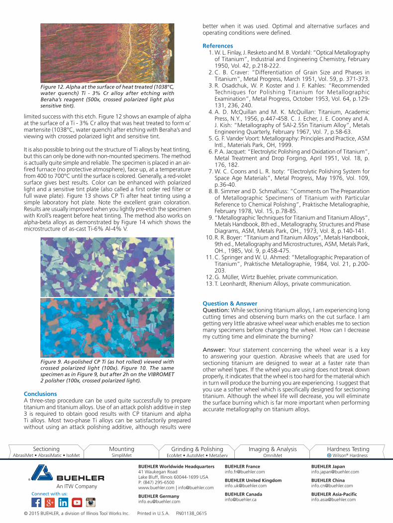
There are a number of color anodizing solutions that have been published. Personally, I have not had much success with these. Most are rather complex solutions to mix and require high voltages. There are also a number of color etchants that have been published. Again, they are challenging to use and get good results. They seem to work best for alpha grades. The color tint etch that has given me the best results is a modification of Weck’s reagent (100mL water, 25mL ethanol, 2g ammonium biflouride, NH4FHF), used by immersion for about 1 minute. As an example, Figure 11 shows two mill-cut edges on a piece of CP Ti after etching with modified Weck’s reagent.
The structure of the burr at the corner is clearly visible as are the deformed grains at the surface. A properly made laboratory abrasive cut will show only a very slight degree of damage. Beraha also developed a tint etch for Ti alloys (2-3g sodium molybdate, 5mL HCI, 1-2g ammonium biflouride, 100mL water) and I have had
Figure 7. Best results obtained for annealed CP Ti (ASTM F67, Grade 2) using the 3-step method of Müller (200x, Kroll’s reagent).
Figure 9. As-polished CP Ti (as hot rolled) viewed with crossed polarized light (100x). Figure 10. The same specimen as in Figure 9, but after 2h on the VIBROMET 2 polisher (100x, crossed polarized light).
Figure 8. Annealed CP Ti (ASTM F67, Grade 2) after using 0.05μm alumina in step 3, with the attack polishing agent (200x, Kroll’s reagent).
Figure 11. CP Ti (annealed at 1038°C) after vibratory polishing and etching with modified Weck’s reagent (100x, crossed polarized light plus sensitive tint).
4
BUEHLER Worldwide Headquarters41 Waukegan RoadLake Bluff, Illinois 60044-1699 USAP: (847) 295-6500www.buehler.com | [email protected]
BUEHLER [email protected]
BUEHLER [email protected]
BUEHLER United [email protected]
BUEHLER [email protected]
BUEHLER [email protected]
BUEHLER [email protected]
BUEHLER [email protected]
Connect with us:
© 2015 BUEHLER, a division of Illinois Tool Works Inc. Printed in U.S.A. FN01138_0615
limited success with this etch. Figure 12 shows an example of alpha at the surface of a Ti - 3% Cr alloy that was heat treated to form α’ martensite (1038°C, water quench) after etching with Beraha’s and viewing with crossed polarized light and sensitive tint.
It is also possible to bring out the structure of Ti alloys by heat tinting, but this can only be done with non-mounted specimens. The method is actually quite simple and reliable. The specimen is placed in an air-fired furnace (no protective atmosphere), face up, at a temperature from 400 to 700°C until the surface is colored. Generally, a red-violet surface gives best results. Color can be enhanced with polarized light and a sensitive tint plate (also called a first order red filter or full wave plate). Figure 13 shows CP Ti after heat tinting using a simple laboratory hot plate. Note the excellent grain coloration. Results are usually improved when you lightly pre-etch the specimen with Kroll’s reagent before heat tinting. The method also works on alpha-beta alloys as demonstrated by Figure 14 which shows the microstructure of as-cast Ti-6% Al-4% V.
ConclusionsA three-step procedure can be used quite successfully to prepare titanium and titanium alloys. Use of an attack polish additive in step 3 is required to obtain good results with CP titanium and alpha Ti alloys. Most two-phase Ti alloys can be satisfactorily prepared without using an attack polishing additive, although results were
better when it was used. Optimal and alternative surfaces and operating conditions were defined.
References1. W. L. Finlay, J. Resketo and M. B. Vordahl: “Optical Metallography
of Titanium”, Industrial and Engineering Chemistry, February 1950, Vol. 42, p.218-222.
2. C. B. Craver: “Differentiation of Grain Size and Phases in Titanium”, Metal Progress, March 1951, Vol. 59, p. 371-373.
3. R. Osadchuk, W. P. Koster and J. F. Kahles: “Recommended Techniques for Polishing Titanium for Metallographic Examination”, Metal Progress, October 1953, Vol. 64, p.129-131, 236, 240.
4. A. D. McQuillan and M. K. McQuillan: Titanium, Academic Press, N.Y., 1956, p.447-458. C. J. Echer, J. E. Cooney and A. J. Kish: “Metallography of 5Al-2.5Sn Titanium Alloy”, Metals Engineering Quarterly, February 1967, Vol. 7, p.58-63.
5. G. F. Vander Voort: Metallography: Principles and Practice, ASM Intl., Materials Park, OH, 1999.
6. P. A. Jacquet: “Electrolytic Polishing and Oxidation of Titanium”, Metal Treatment and Drop Forging, April 1951, Vol. 18, p. 176, 182.
7. W. C. Coons and L. R. Isoty: “Electrolytic Polishing System for Space Age Materials”, Metal Progress, May 1976, Vol. 109, p.36-40.
8. B. Simmer and D. Schmalfuss: “Comments on The Preparation of Metallographic Specimens of Titanium with Particular Reference to Chemical Polishing”, Praktische Metallographie, February 1978, Vol. 15, p.78-85.
9. “Metallographic Techniques for Titanium and Titanium Alloys”, Metals Handbook, 8th ed., Metallography, Structures and Phase Diagrams, ASM, Metals Park, OH., 1973, Vol. 8, p.140-141.
10. R. R. Boyer: “Titanium and Titanium Alloys”, Metals Handbook, 9th ed., Metallography and Microstructures, ASM, Metals Park, OH., 1985, Vol. 9, p.458-475.
11. C. Springer and W. U. Ahmed: “Metallographic Preparation of Titanium”, Praktische Metallographie, 1984, Vol. 21, p.200-203.
12. G. Müller, Wirtz Buehler, private communication.13. T. Leonhardt, Rhenium Alloys, private communication.
Question & AnswerQuestion: While sectioning titanium alloys, I am experiencing long cutting times and observing burn marks on the cut surface. I am getting very little abrasive wheel wear which enables me to section many specimens before changing the wheel. How can I decrease my cutting time and eliminate the burning?
Answer: Your statement concerning the wheel wear is a key to answering your question. Abrasive wheels that are used for sectioning titanium are designed to wear at a faster rate than other wheel types. If the wheel you are using does not break down properly, it indicates that the wheel is too hard for the material which in turn will produce the burning you are experiencing. I suggest that you use a softer wheel which is specifically designed for sectioning titanium. Although the wheel life will decrease, you will eliminate the surface burning which is far more important when performing accurate metallography on titanium alloys.
Figure 12. Alpha at the surface of heat treated (1038°C, water quench) Ti - 3% Cr alloy after etching with Beraha’s reagent (500x, crossed polarized light plus sensitive tint).
Figure 9. As-polished CP Ti (as hot rolled) viewed with crossed polarized light (100x). Figure 10. The same specimen as in Figure 9, but after 2h on the VIBROMET 2 polisher (100x, crossed polarized light).