Embed Size (px)
Citation preview

2019
Pipeline and Hazardous Materials
Safety Administration
U.S. Department of Transportation
3/21/2019
Metallurgical Laboratory Failure Examination Protocol

Page 1 of 30
Metallurgical Laboratory Failure Examination Protocol Created 08/23/2006 (Rev. 04/04/2019)
Metallurgical Laboratory Failure Examination Protocol
TABLE OF CONTENTS Metallurgical Laboratory Failure Examination Protocol ................................................................ 0
Introduction ................................................................................................................................. 2
Background and Photographic Information Collection .............................................................. 3
Removal of Failed Section and Transfer of Custody .................................................................. 3
Physical Measurements ............................................................................................................... 5
Corrosion Examination ............................................................................................................... 6
Fractographic Examination ......................................................................................................... 7
Metallographic Examination ....................................................................................................... 7
Mechanical Properties ................................................................................................................. 8
• Tensile Testing ................................................................................................................. 8
• Charpy V-notch Impact Testing ....................................................................................... 8
• Chemical Analysis............................................................................................................ 9
• Background Information Data Sheet .............................................................................. 10
• A testing methodology for generating Charpy V-notch Curves for line pipe steels ...... 13
Attachment 1 – Evidence Custody Transfer Control Procedures ............................................. 15
SECTION 1 - Gathering Physical Evidence ......................................................................... 15
SECTION 2 - Gathering Documentation .............................................................................. 16
SECTION 3 - Controlling Evidence ..................................................................................... 16
Evidence Tag Example: ............................................................................................................ 18
Evidence Collection List ........................................................................................................... 19
Evidence Control Form ............................................................................................................. 20
Master Evidence Log ................................................................................................................ 21
Attachment 2 – Metallurgical Testing Worksheets .................................................................. 22
SECTION 1 – Mechanical Testing worksheet ...................................................................... 23
SECTION 2 – Fracture Sketch and Measurements worksheet ............................................. 25
SECTION 3 – Chemical Analysis worksheet ....................................................................... 27
SECTION 4 – Metallographic Specimens and Photograph worksheet ................................ 29

Page 2 of 30
Metallurgical Laboratory Failure Examination Protocol Created 08/23/2006 (Rev. 04/04/2019)
Introduction The objective of a metallurgical analysis of a line pipe failure is to identify one or more primary or secondary causes for the failure. The metallurgical analysis should identify issues that must be remediated to ensure the integrity of other sections of the failed line pipe as well as other pipeline segments with similar characteristics (i.e. pipe manufacturer, seam type, grade, other specifications, coating type, and environmental conditions). The metallurgical failure analysis should be conducted by trained and experienced individuals. This protocol specifically addresses the failure analysis of line pipe. Failure analysis of pipeline appurtenances (such as pumps, fittings, valves, flanges, bolts, tanks, scrubbers, barrels, etc.) may use the same methodologies as those outlined herein, but a unique test plan shall be developed to handle the unique characteristics of the appurtenance. A plan shall be developed prior to the beginning of field collection of evidence and specimens. The plan shall be based on a very logical and methodical engineering analysis of the event and knowledge of the metallurgical investigation process. Prior planning prevents poor performance and missed opportunities. Besides a metallurgical analysis of the line pipe failure, the internal and external environment of the line pipe must also be analyzed to arrive at the causal factors of the failure. Therefore, the presence of corrosion products inside and outside the line pipe in the area of the failure must be analyzed and collected for analysis, as appropriate. For example, soil in the immediate area of the failure, dislodged soil adjacent to the ejected pipe, and soil that had adhered to the line pipe may (based upon an engineering analysis) have to be collected for analysis. Photographic documentation of the failed section of line pipe prior to its departure from the accident site and upon its arrival at the testing facility must be available to ensure any damage from mishandling is appropriately noted. Before the shipment of the failed section, proper preservation techniques for the fracture surfaces and the section (including coating), if required, shall be identified (such as Visqueen®, SaranWrap®, oils, and other protective covers), and a chain of custody shall be established for transfer of the failed section to the testing facility. Chain of custody procedures must be followed throughout the transport process to the testing facility. Before the failed section arrives at the testing facility, it shall be determined if destructive testing of the failed section has been approved. Only non-destructive testing is allowed in some instances to preserve the pipe intact for evidentiary purposes. In some instances, destructive testing can only occur when all interested parties agree and a consensus protocol can be developed. This document provides a typical sequence of a failure analysis. This document is general in nature, and it is important to note, that the results at each step of the analysis sequence dictates the next step to be performed. Additionally, sound engineering decisions must be made during any failure analysis, and the need for additional tests to be performed is a determination that shall be made during the course of the investigation. In some instances, testing of samples of pipe from adjacent joints or segments may be necessary. As an example, when the pipe has been exposed to a fire, pipe from outside the heat affected area shall be tested. In these instances, the proposed test plan shall be modified to reflect these additional tests. The following serves as guidance in conducting a failure analysis following a pipeline failure.
• Background and photographic information collection • Verification that all ejected specimens are recovered

Page 3 of 30
Metallurgical Laboratory Failure Examination Protocol Created 08/23/2006 (Rev. 04/04/2019)
• Visual and non-destructive examination • Physical measurements of site • Physical measurements of pipe • Removal of failed section and transfer of custody • Corrosion examination • Fractography examination • Metallographic examination • Mechanical properties
Background and Photographic Information Collection Background information about the failed pipeline’s operating history, attributes and specifications of the failed pipeline, and the operating pressure and failure pressure shall be collected. This type of background information provides investigators with the crucial data to understand the technical environment in which the pipeline was operating and assists in identifying potential contributing causes to the failure. Table 1 provides guidance on data that may be collected during the failure investigation. Photographic evidence shall be collected to document the failure site and other pertinent details regarding the failure. Photographic documentation includes, but is not limited to the following:
• Overview of failure site including local topography • Overview of line pipe failure area • Detail of fracture surface(s), magnified appropriately to show all relevant features at the
fracture surfaces and the fracture origin • Detail of coating in area of failure • Detail of areas of internal and external corrosion near the fracture surface • Details of residues or corrosion products near the fracture surface • Details of areas indicating outside force damage
Removal of Failed Section and Transfer of Custody A plan shall be developed with input from all parties involved prior to cutting on the pipe. Interested parties shall be given adequate time to view, photograph, and document. Prior to removing the failed section of pipe, consider the collection of soil samples, if appropriate, as discussed above. When removing the failed section, any indication of residual stress in the line shall be documented. Spring or movement of the pipe when the first circumferential cut is completed would indicate the presences of residual stress. If a flame cut is used to remove the failed section, do not flame cut within twelve inches of the fracture or failure surfaces as the heat from the torch could change the metallurgical characteristics of the steel. Hot work permits are appropriate for flame cutting (follow operators’ safety procedures). The location and distance between the cut ends after the first cut is completed shall be documented along with flow direction and top-of-pipe location.

Page 4 of 30
Metallurgical Laboratory Failure Examination Protocol Created 08/23/2006 (Rev. 04/04/2019)
When handling sections containing the failure area and/or fracture surfaces, care must be taken to preserve these sections in their original condition in order to provide optimal information in determining the cause(s) of the failure. For any failure, the following are guidelines in preparing the samples of failed sections for analysis and shall be followed as appropriate:
• Do not mechanically clean, sandblast, wire-brush, or acid clean any failed specimens prior to proper analysis. Deposits on the failed part or section might be helpful in determining the cause(s) of the failure.
• If a part is fractured into two or more separate pieces, do not fit the fracture surfaces back together as one can easily damage the fracture surface further. Certain metallurgical features on the fracture surface can help to determine the cause(s) of the failure.
• Only apply preservatives (e.g. WD40, grease or oil) to fracture surfaces when directed to do so. The integrity of surface deposits and corrosion products could be compromised the application of preservatives to the fracture surfaces. If applied upon direction, the lubricating oil can be removed prior to fractographic analysis.
• Wrap the failed section in plastic in its "as is condition” without removal of any surface deposits.
• Do not store or house any portions of the failed pipeline section outside for long periods of time as continuous exposure to environmental elements can compromise or change the composite of a failed part or section.
When transporting the physical evidence, the chain of custody procedures found in Attachment 1 must be followed. Visual and Nondestructive Examination 1. Once the failed pipe section is received at the laboratory, photographically document the pipe
in its “as-received” condition before initiating the metallurgical analysis. Photographic documentation shall include, but is not limited to the following: • Fracture area and surface • Seams • Girth welds • Coating condition • Anomalies • Manufacturing flaws or defects • Pitting and/or evidence of corrosion on internal and external pipe surfaces
2. Perform a visual examination of the internal and external pipe surfaces in its “as-received”
condition, and document through notes and photos any anomalies that could be present in the pipe, including the following: • Cracks • Crevices • Dents • Bends • Buckles • Gouges • Manufacturing defects • Wrinkles, tents or damage to the coating • Pitting and/or evidence of corrosion on internal and external pipe surfaces

Page 5 of 30
Metallurgical Laboratory Failure Examination Protocol Created 08/23/2006 (Rev. 04/04/2019)
• Presence of corrosion products and/or deposits • Describe coating, and coating damage (disbonding) if any, in the vicinity of fracture
origin and at other locations in the failed pipe sample • Describe any internal coating or linings (if used) • Examine the pipe sample surface for evidence of stress corrosion cracking • Examine for evidence of arc burns, excessive grinding around the surface area near the
crack • If corrosion is evident, collect corrosion products for analysis
3. Collect solid and liquid samples, if present, from the pipe surface, and conduct elemental
analysis and microbial tests on these samples, as appropriate (based on sound engineering analysis). Examples of samples that may be collected include, but are not limited to, the following: • Liquid accumulated underneath the coating. If not enough liquid is present for collection,
consider using pH paper to characterize pH. • Corrosion products and/or deposits from the internal and external surfaces of pipe surface • Soil adhering to the pipe
4. If coating is to be removed, it shall be removed in a manner that will not be injurious to the
pipe. Photographically document and visually inspect the pipe again following coating removal (see 1. and 2. above for guidance). Note any disbondment or possible adhesion problems with coating.
5. It may be necessary (based on sound engineering analysis) to inspect the failed section of pipe
for cracking, stress corrosion cracking, or any other condition that could affect the long-term integrity of the pipeline using nondestructive testing techniques. The surfaces of the pipe surrounding the rupture shall be cleaned with an appropriate non-abrasive cleaner and subsequently inspected using a wet fluorescent magnetic particle inspection (WFMT) method. The WFMT method is preferred because internal and external defects can be readily identified with this method. Other nondestructive examination techniques such as Dye Penetrant, Radiographic, Eddy-Current, Ultrasonic Inspection, and Alternating Current Potential Drop may (based on sound engineering analysis) also be used.
6. The physical location of all samples to be removed from the pipe for examination and
metallurgical analysis shall be photographed and documented such that all relevant features of the samples are visible and noted prior to removal.
Physical Measurements 1. Measure the diameter and wall thickness on undisturbed areas of the pipe to confirm
information provided in the “Background Information Data Sheet” is accurate. 2. Measure and record the diameter and wall thickness at selected locations to determine actual
values at these selected locations. Measure and record the diameter and wall thickness of the pipe at each end of each sample. (Wall thickness shall be determined based upon four measurements taken 90 degrees apart.)
3. Verify roundness and geometry of pipe at the extremities and closer to the failed surface.
Page 6 of 30
Metallurgical Laboratory Failure Examination Protocol Created 08/23/2006 (Rev. 04/04/2019)
4. Measure and record the wall thickness around fracture surfaces and any damaged areas. If corrosion is identified near or around the fracture surfaces, a “corrosion map” shall be produced detailing the extent of the corrosion on the pipe surfaces and the pipe wall thicknesses in those areas. Laser scanning could be appropriate. This information will be needed to support remaining strength calculations, if required.
5. Align the pipe samples to conform to the pre-fracture bend geometry. 6. Determine and mark the location of the electric-resistance weld at each end of each sample. 7. Determine whether or not any part of each rupture falls within the electric-resistance weld
zone. 8. Measure and record the length of each sample. 9. Record any markings detected on the inside or outside surfaces of the pipes. 10. Measure and record rupture lengths tip-to-tip. 11. Measure and record the shortest circumferential distance from each fracture origin to the
nearest electric-resistance weld. 12. Measure and record the axial distance from each fracture origin to the nearest girth weld, if
any. 13. Map wall thickness of each sample within 12 inches upstream and downstream of each
rupture origin. Measurements shall be taken on a 2-inch square grid pattern or other appropriately sized grid pattern that is centered on the fracture origin and that encompasses 100 percent of the pipe circumference at each origin.
14. Determine depths of cracks using direct exploration (grinding), shear wave ultrasonic testing (UT), Alternating Current Potential Drop (ACPD) or other suitable methods.
Attachment 2 provides a worksheet for documenting physical measurements.
Corrosion Examination Surface deposits and residues associated with the fracture surface area and adjacent areas shall be collected and analyzed to characterize and determine the origin of the deposits. Attachment 2 provides a worksheet for documenting chemical analysis results of corrosion products. Based on the results of the visual, non-destructive, and metallographic examinations, the presence of corrosion shall be documented, and the type and characteristics of any corrosion present shall be evaluated. Remaining strength calculations (RSTRENG/ASME B31G) shall be performed on corroded areas to support the failure investigation. If an in-line inspection (ILI) tool has inspected the failure site in the past, investigation of the ILI logs and reports can provide information relevant to corrosion growth rate. Request a copy of the ILI log and report to review. In the event an anomaly is present in the ILI report, it is important to follow up with the operator about the company’s excavation criteria in effect at the time of the ILI and the application of RSTRENG calculations and anomaly interaction criteria.

Page 7 of 30
Metallurgical Laboratory Failure Examination Protocol Created 08/23/2006 (Rev. 04/04/2019)
Fractographic Examination Fractographic examination is the study of the broken surfaces of the pipe with the purpose of determining the cause of the failure. By studying the characteristics of the fracture surface(s), information can be gathered as to the origin of a crack and/or the cause, such as corrosion, crack growth, third-party damage, weld failure or fatigue etc. 1. Visually examine the fracture surfaces in detail to identify the characteristics of the fracture,
the nature of the original defect, and the failure initiation point(s). It could become necessary to open the fracture surface in order to conduct part of the examination, and a suitable technique that is dependent upon the particular circumstances of the failure shall be used to open the fracture surface.
2. Clean samples in an appropriate manner (Endox or Citronox solution, ultrasonic cleaner) to
remove loose rust, scale, etc. as necessary. 3. Utilize a suitable method to thoroughly document the fracture surface including dimensional
documentation. Suitable methods to document the fracture surface include, but are not limited to, the following: • Foil method • Photographs of macroscopic examination
4. Remove selected fractographic samples as necessary for detailed microscopic examination using optical or scanning electron microscope. Examine and document the fracture surface morphology. When chevron marks are present on the fracture surface, they typically point back towards the fracture origin in steels. It is important to be able to characterize the fracture surface morphology, and fractures can be classified into four groups on a macroscopic scale, as follows: • Ductile fractures • Brittle fractures • Fatigue fractures • Fractures resulting from combined effects of stress and environment
5. Under magnification, observe specimen for signs of striations and/or the start stop progression
of a crack feature. If fatigue is observed, document and describe the evidence.
Metallographic Examination 1. Identify and document metallographic sample origin areas, including sample identification,
location, orientation, etc.; perform metallographic evaluation; and take representative photomicrographs. Areas of particular concern are: • At or near the fracture origin • Fracture surfaces • Weld seams • Anomalies • Areas with indications of defects or cracks identified through visual and/or non-destructive
testing

Page 8 of 30
Metallurgical Laboratory Failure Examination Protocol Created 08/23/2006 (Rev. 04/04/2019)
• Areas exhibiting “typical” microstructures of the base metal, weld metal, and heat-affected-zone
2. Perform micro-hardness profiles at appropriate locations such as the following:
• At or near the fracture origin • Weld seams • Weld metal and heat affected zones
3. Metallographic samples shall be examined to characterize and validate any appropriate issues
specific to the failure such as: • Pipe specification, grade, and heat treatment • Weld seam in area of fracture • Weld seam in un-affected area • Corrosion • Indications of outside force damage
Attachment 2 provides a worksheet for documenting metallographic specimens and photographs. Mechanical Properties Testing shall be performed to determine the mechanical properties of the pipe and any appurtenances. Mechanical properties of test specimens shall not be taken from areas of the pipe that have been plastically deformed as a result of the failure. Additionally, mechanical properties of pipe exposed to fire are of limited viability. These mechanical tests shall at least include the following:
• Tensile Testing Tensile test specimens shall be prepared and tested in accordance with ASTM A370 (Mechanical Testing of Steel Products) for the pipe base metal and weld seams to measure yield strength, ultimate tensile strength, and elongation. The pipe base metal shall, at a minimum, be tested in the transverse direction, and weld seam specimens shall be taken across the weld seam.
• Charpy V-notch Impact Testing When Charpy V-notch (CVN) Impact Testing is determined to be necessary, the CVN specimens shall be prepared and tested in accordance with ASTM E23 (Notched Bar Impact Testing of Metallic Materials) to determine the toughness characteristics of the pipe in the L-T (transverse) direction. In some cases, depending on pipe size and wall thickness, it may be necessary to use sub-size CVN specimens, and these results shall be corrected back to full sized specimen values using the formula provided in Table 2. Results from CVN testing may be reported in some or all of the following forms depending on the testing results:
• Upper-Shelf Energy (in ft-lbs) • Lower-Shelf Energy (in ft-lbs) • Ductile-to-Brittle Transition Temperature (in °F) determined from graphical representation
of testing results at the midpoint of the best-fit curve

Page 9 of 30
Metallurgical Laboratory Failure Examination Protocol Created 08/23/2006 (Rev. 04/04/2019)
• Test Temperature corresponding to 15 ft-lbs of absorbed impact energy • Fracture Appearance Transition Temperature (in °F) corresponding to 50% and 80% shear • Lateral expansion (to measure notch toughness)
In some steels, it could be difficult to measure percent shear because of “woody” fracture surfaces. In these cases, it would be more appropriate to use lateral expansion and absorbed energy measurements to obtain a more accurate transition temperature. A sample testing methodology for generating Charpy V-notch Curves for line pipe steels is provided in Table 2.
• Chemical Analysis The chemical composition of the pipe material shall be determined using an appropriate method to validate the pipe specification and grade, as well as, to determine its carbon equivalent (for weldability issues). Spectrochemical methods (i.e. optical emission) are usually employed to determine steel chemical compositions. Wet chemical methods could also be used. Energy dispersive spectroscopy (EDS) and either x-ray diffraction (XRD) or x-ray photoelectron spectroscopy (XPS) analyses could be used to determine elements and compounds present in surface deposits that were collected during the visual examination. Attachment 2 provides a worksheet for documenting mechanical tests performed and a worksheet for documenting the chemical analysis tests performed on the pipe steel.

Page 10 of 30
Metallurgical Laboratory Failure Examination Protocol Created 08/23/2006 (Rev. 04/04/2019)
• Background Information Data Sheet complete all applicable fields
No. Line Pipe Attribute Data
1 Operating Company
2 Product Transported
3 Line Name and Number and/or System Name
4 Survey Station and Mile Post
5 Date of Failure / Incident / Anomaly
6 How Failure / Incident / Anomaly was found
7 Closest City or town, County, and State
8 Pipe Nominal Outside Diameter
9 Pipe Nominal Wall Thickness
10 Pipe Grade
11 Pipe Seam Type and approx. Joint Length
12 Pipe Manufacturer
13 Year of Installation
14 Depth of Cover in area of failure
15 Coating Type
16 Cathodic Protection Type and Year installed (if applicable)
17
Distance to nearest rectifier or anode bed (if applicable) (Note any Pipe-to-Soil Readings or Surveys done before accident)
18 Terrain and Soil Conditions, including Soil Ph (if applicable)

Page 11 of 30
Metallurgical Laboratory Failure Examination Protocol Created 08/23/2006 (Rev. 04/04/2019)
No. Line Pipe Attribute Data
19 Distance to Upstream and Downstream Compressor or Pumping Station
20 Distance to Upstream and Downstream Girth Welds
21 Position of Failure / Incident / Anomaly on Pipe (from top or bottom and/or O’clock position)
22 Pressure at time and location of Failure / Incident / Anomaly
23 Normal Operating Pressure at Location of Failure / Incident / Anomaly
24 MOP, MAOP, Design Factor, and/or Location Class
25 Date, Test Pressure, and Duration of most recent Hydrostatic Test (if applicable). Note any test failures and probable cause
26 Hydrostatic Test Pressure at Location of Failure / Incident / Anomaly (if applicable)
27 Note the date of the last in-line inspection (ILI) and any anomalies or repairs near failure site
28 Note any previous NDT test performed in or around the failure site (X-rays, UT scans, etc)
29 Note any historical pictures of failure site
30 Other Comments or Observations
31 Name, Telephone, and Fax Numbers of contact for Operator for further Questions

Page 12 of 30
Metallurgical Laboratory Failure Examination Protocol Created 08/23/2006 (Rev. 04/04/2019)
No. Line Pipe Attribute Data
32 Name, Telephone, and Fax Numbers of contact for OPS for further Questions
33 NRC Report Number (if applicable)
Sketch a schematic of the failure area showing direction of flow and other prominent features:

Page 13 of 30
Metallurgical Laboratory Failure Examination Protocol Created 08/23/2006 (Rev. 04/04/2019)
• A testing methodology for generating Charpy V-notch Curves for line pipe steels
Note: The following is an example test protocol to generate a Charpy V-notch (CVN) Curve and to determine the Ductile-to-Brittle Transition Temperature (DBTT) for API-X52 and lower grade line pipe. Prepare a minimum of 12 Charpy V-notch specimens (preferably 16 specimens) in the L-T (transverse) direction and perform CVN testing according to ASTM E23.
Test 1 specimen at -20°F
Test 1 specimen at 0°F
If CVN values are less than 4 ft-lbs. (full scale), then consider this a part of the lower shelf temperatures
Test 1 specimen at 70°F
Test 1 specimen at 100°F
If CVN values are greater than 20 ft-lbs. and are close together, then consider this part of the upper shelf temperatures. If the difference in CVN values is more than 5 ft-lbs., then:
Test 1 specimen at 70°F
Test 1 specimen at 50°F
If CVN values are close together, then the DBTT is likely to be around 50°F, then:
Test 1 specimen at 50°F
Test 1 specimen at 40°F
Test 1 specimen at 20°F
If the difference in CVN values at 50°F and 70°F is greater than 5ft-lbs., then
Test 1 specimen at 50°F
Test 1 specimen at 60°F
Test the remaining specimens at other temperatures, as appropriate, to ensure that data has been collected at temperatures that the testing has shown to be of importance.
Draw the CVN Curve to a best-fit curve plotting Impact Energy (ft-lbs.) versus Temperature (°F).
Determine the DBTT from the CVN Curve (in °F) based on the best-fit curve midpoint.
Determine the Temperature (in °F) corresponding to 15 ft-lbs. absorbed impact energy.

Page 14 of 30
Metallurgical Laboratory Failure Examination Protocol Created 08/23/2006 (Rev. 04/04/2019)
Determine the Fracture Appearance Transition Temperature (FATT) corresponding to 50% and/or 80% shear (ductile failure).
Determine the Upper-Shelf Energy (in ft-lbs.).
Determine the Lower-Shelf Energy (in ft-lbs).
If a sub-scale CVN specimen is used (less than 10 mm), determine the FATT for a full sized CVN specimen using the following formula: TD = TC + 66(tW0.55 / tC0.7 ) – 100 ,Where: TD - FATT converted to a full scale specimen (10 mm) at 80% shear) TC – Actual FATT measured at 80% shear tW - actual pipe wall thickness tC - actual CVN specimen thickness

Page 15 of 30
Metallurgical Laboratory Failure Examination Protocol Created 08/23/2006 (Rev. 04/04/2019)
Attachment 1 – Evidence Custody Transfer Control Procedures PURPOSE: To provide guidance for gathering, preserving and controlling evidence. SECTIONS: 1. Gathering Physical Evidence 2. Gathering Documentation 3. Controlling Evidence
SECTION 1 - Gathering Physical Evidence 1. Before disturbance, photograph the incident scene using still and video cameras to document
the site at initial entry. 2. Before collection, label and photograph evidence to be removed. Prepare and prioritize a list
of the physical evidence to be gathered and/or analyzed. Collect any perishable evidence as soon as it can be accessed after arrival at the site.
3. Prior to removing evidence, notify all other agencies and company officials of the schedule for its removal. Determine whether this evidence has been or is scheduled to be removed or analyzed by other PHMSA investigators, other agency investigators, or company officials. Coordinate with these individuals to ensure that PHMSA’s issues will be resolved.
4. Coordinate with other PHMSA investigators, other agency investigators, and company officials to determine whether they have other issues that an analysis of the physical evidence can resolve, or if they have concerns about the analysis or removal of the item.
5. Fully photograph all physical evidence before it is moved. Ensure that the position of the evidence within the context of the incident scene is recorded.
6. Document the scene from a wide angle to a narrow angle to ensure the context of the scene is understood later. Perform a running narration when using the video camera.
7. Photograph physical evidence from multiple angles. 8. Place a ruler, scale, or other recognizable item near physical evidence to indicate size and
distance. During photography, macro measurement of the failed parts and other pertinent components shall be made.
9. Complete a log entry for each photographic activity. Label all photographic media with the incident ID, time, date, and location of the photography, photographer, and a short description of the contents of the photographic record.
10. Determine whether an analysis of an item is required. Including NDE, examining in a laboratory of; parts, components, corrosion product, coating samples, liquids w/syringe and other related evidence.
11. If analysis is required, determine whether the analysis can be conducted at the scene or will have to be conducted externally.
12. Label the evidence at the scene with the PHMSA incident ID, date, time, location of the evidence, name of the investigator, and evidence tracking number. Photograph labeled evidence for pattern analysis before removing.

Page 16 of 30
Metallurgical Laboratory Failure Examination Protocol Created 08/23/2006 (Rev. 04/04/2019)
13. Protect the evidence from further damage and/or contamination, as described in the analysis plan for this evidence. Preservation of evidence includes bubble wrap and only use a benign protective oily spray or grease on items when directed to do so. Packaging shall only be removed, analyzed, or examined in a laboratory. Wrapping the evidence with “Saran” wrap or other plastic wrap in preparation for transport is appropriate as long as moisture is not locked in the package such that corrosion could take place.
14. If the evidence will be removed, identify a suitably secure location to store the evidence for later analysis in accordance with the plan requirements. If evidence consists of sections of pipe, valves and other large components, they shall be placed in a secure place such as warehouses, hangers and areas with locked fences covered with plastic awning.
15. Remove the evidence, if appropriate/necessary (if the evidence removal requires a third-party specialist, coordinate with appropriate entities). Only certain people are qualified for this (e.g. the lead investigator or qualified third party).
16. Ensure that the removal has been recorded and document its custody. 17. Perform the required analysis in accordance with the analysis plan.
SECTION 2 - Gathering Documentation 1. Note: When the investigator obtains documents from companies or private entities, he or she
shall request that the company or private entity mark all information that it believes contains trade secrets or confidential business information (CBI).
2. Obtain documentation requests from the investigators. 3. Transmit the request. 4. Assign an easily comprehensible tracking number to the documentation request. 5. Record documentation requested in the Evidence Collection List. 6. If the documentation is not received by the time indicated on the request form, consult with
the requesting investigator to determine whether he or she still needs the document. 7. If the investigator still needs the documentation, consult with appropriate entities. 8. Once the documentation is received and logged, give it to the requesting investigator. 9. A procedure shall be included to obtain names and contact information of all witnesses directly
related to the incident.
SECTION 3 - Controlling Evidence 1. Assign an information type code to the evidence or document and apply it to the evidence.
Coordinate with tracking number 2. Obtain the evidence and any additional information or notes regarding the evidence from the
investigator. 3. Date stamp the evidence (this may require using an evidence tag). 4. Generate an Evidence Control Form and complete an Evidence Control Form entry for the
information or evidence.

Page 17 of 30
Metallurgical Laboratory Failure Examination Protocol Created 08/23/2006 (Rev. 04/04/2019)
5. Attach the Evidence Control Form to the physical evidence/notes, if available. 6. Complete a Master Evidence Log entry for the new evidence. 7. File the Evidence Control Form according to the information type code and securely store it. 8. Lock the room and/or file cabinet in which controlled information or evidence is stored when
you are not physically present. 9. Ensure that computer-based information or evidence is password-protected. 10. Sign-out evidence into/from the locked storage area. 11. Maintain the evidence in your immediate possession at all times when it is removed from the
locked storage area.

Page 18 of 30
Metallurgical Laboratory Failure Examination Protocol Created 08/23/2006 (Rev. 04/04/2019)
Evidence Tag Example:
Evidence and Custody Transfer Tag (Example)
Incident Type:
Tracking No.:
Date Collected:
Collected By:
Location:
Operator:
System:
Disposition: Where the evidence is to be taken and by whom; (origin; destination; shipper). As evidence custody is transferred, each receiver shall sign form and identify their agency.
Received From:
Received By:
Date: Time:
Received From:
Received By:
Date: Time:
Item Description and Notes

Page 19 of 30
Metallurgical Laboratory Failure Examination Protocol Created 08/23/2006 (Rev. 05/16/2018)
Evidence Collection List
Priority Description Information Type Code
Owner Requested?
Notes and Comments

Page 20 of 30
Metallurgical Laboratory Failure Examination Protocol Created 08/23/2006 (Rev. 05/16/2018)
Evidence Control Form
Evidence Identification Tracking Number
Date Received Item Description Storage Location
Action Log Date Action (e.g.
checked out, returned, shipped)
Person/Organization Current Location Notes

Page 21 of 30
Metallurgical Laboratory Failure Examination Protocol Created 08/23/2006 (Rev. 05/16/2018)
Master Evidence Log
Tracking #
Supplying Organization’s
Tracking #
Date Received
Item Description Received by:
Received From:
Notes:

Page 22 of 30
Metallurgical Laboratory Failure Examination Protocol Created 08/23/2006 (Rev. 05/16/2018)
Attachment 2 – Metallurgical Testing Worksheets PURPOSE: To provide sample worksheets for documenting testing that is performed in support of the metallurgical analysis. SECTIONS: 1. Mechanical Testing worksheets 2. Fracture Sketch and Physical Measurements worksheet 3. Chemical Analysis worksheet 4. Metallographic Specimens and Photograph worksheet

Page 23 of 30
Metallurgical Laboratory Failure Examination Protocol Created 08/23/2006 (Rev. 05/16/2018)
SECTION 1 – Mechanical Testing worksheet
Test Locations: (e.g.; specific segment of pipe; location; comments)
Table 1 Transverse Pipe Body Tensile Test Results
Test Location Yield Strength (PSI) Tensile Strength (PSI) % Elongation in 2”
Table 2 Transverse Weld Tensile Test Results
Test Location Tensile Strength (PSI) % Elongation in 2” Fracture Location
Table 3 Transverse Pipe Body Charpy Tests Specimen Size - ____ mm x 10 mm
Test Temperature
(° F)
Absorbed Energy (ft-lbs)
Absorbed Energy adjusted to normal size
Specimen (ft-lbs)
Lateral Expansion (mils)
% Shear
Page 24 of 30
Metallurgical Laboratory Failure Examination Protocol Created 08/23/2006 (Rev. 05/16/2018)
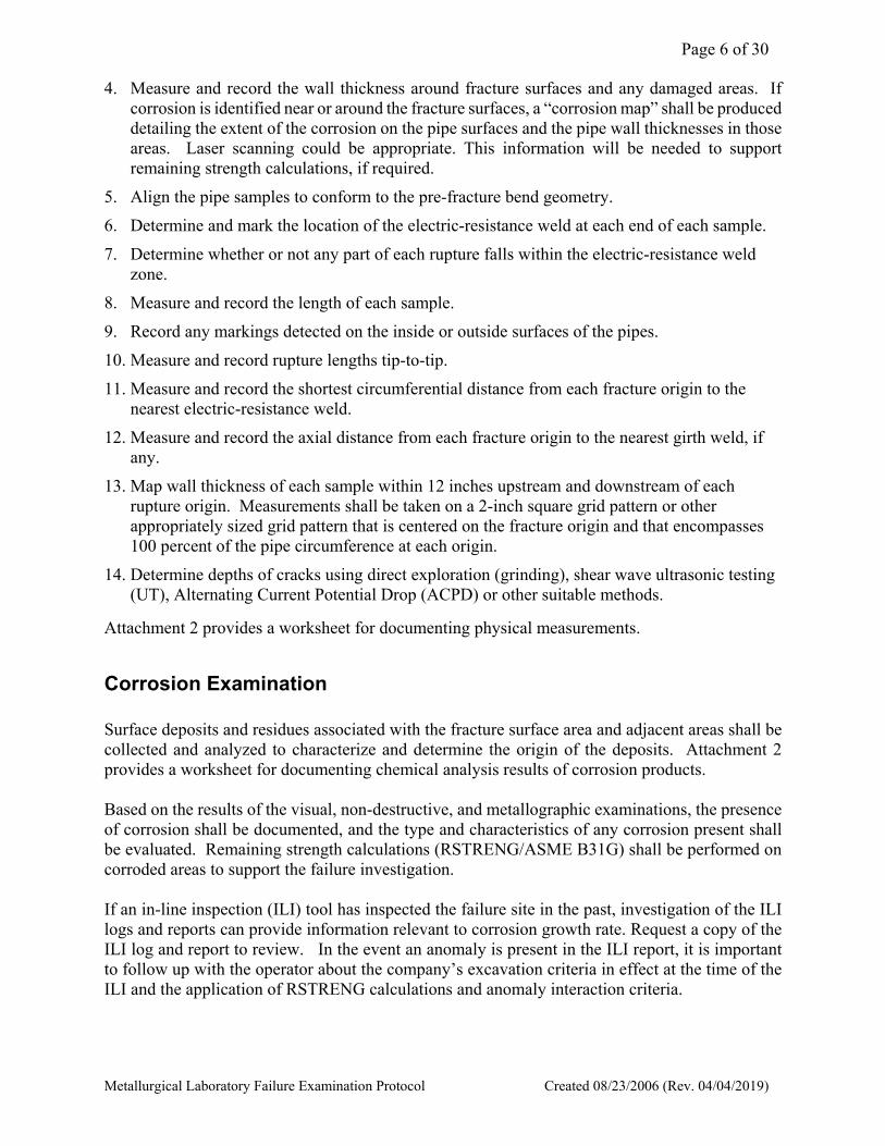
Table 4 Transverse Weld & HAZ Charpy Tests
Specimen Size - ____ mm x 10 mm
Test Temperature
(° F)
Absorbed Energy (ft-lbs)
Absorbed Energy adjusted to normal size
Specimen (ft-lbs)
Lateral Expansion (mils)
% Shear

Page 25 of 30
Metallurgical Laboratory Failure Examination Protocol Created 08/23/2006 (Rev. 05/16/2018)
SECTION 2 – Fracture Sketch and Measurements worksheet
Notes: ________________________________________________________________________ ______________________________________________________________________________ ______________________________________________________________________________
Longitudinal Length (in):
Max. Opening Width (in):
Long Seam Position (O’clock):
OD at Pipe End (0º-180º):
OD at Pipe End (90º-270º):
Wall Thickness Survey at Pipe Ends
Circumferential Position Upstream End Downstream End
12:00
1:00
2:00
3:00
4:00

Page 26 of 30
Metallurgical Laboratory Failure Examination Protocol Created 08/23/2006 (Rev. 05/16/2018)
5:00
6:00
7:00
8:00
9:00
10:00
11:00

Page 27 of 30
Metallurgical Laboratory Failure Examination Protocol Created 08/23/2006 (Rev. 05/16/2018)
SECTION 3 – Chemical Analysis worksheet
Test Locations: (e.g.; specific segment of pipe; location; comments)
Table 1 Chemical Analysis
Element Weight Percent Element Weight Percent
Carbon (C) Molybdenum (Mo)
Manganese (Mn) Columbium (Cb)
Phosphorus (P) Vanadium (V)
Sulfur (S) Titanium (Ti)
Silicon (Si) Cobalt (Co)
Aluminum (Al) Tin (Sn)
Copper (Cu) Arsenic (As)
Nickel (Ni) Boron (B)
Chromium (Cr) Calcium (Ca)
Table 2 Chemical Analysis of Corrosion Products present at Failure Site
Location Significant Constituents Comments and Findings
Table 3 Chemical Analysis of Liquids or other Materials of interest present at Failure Site
Location Significant Constituents Comments and Findings

Page 28 of 30
Metallurgical Laboratory Failure Examination Protocol Created 08/23/2006 (Rev. 05/16/2018)
Remarks:

Page 29 of 30
Metallurgical Laboratory Failure Examination Protocol Created 08/23/2006 (Rev. 05/16/2018)
SECTION 4 – Metallographic Specimens and Photograph worksheet
Metallographic Specimen worksheet
Sample # Location Description
Metallographic Sections and Photograph worksheet
Photo# Sample # Mag Etchant Description

Page 30 of 30
Metallurgical Laboratory Failure Examination Protocol Created 08/23/2006 (Rev. 05/16/2018)


![Oxidation of Graphite and Metallurgical Coke1033035/FULLTEXT01.pdfFigure 3: A cooking oven at the company DPL in India [7]. Before the black coal arrives at the cooking oven, there](https://img.pdfslide.net/doc/110x75/6079b149dcde263c05648771/oxidation-of-graphite-and-metallurgical-1033035fulltext01pdf-figure-3-a-cooking.jpg)