Embed Size (px)
Citation preview

Proceedings of Metal 2004 National Museum of Australia Canberra ACT 4–8 October 2004 ABN 70 592 297 967
© Published by the National Museum of Australia www.nma.gov.au
Metallurgy of armour exhibited at the Palace Armoury Valletta, Malta.
D. Vella
a, C. Degrigny
a, M. Grech
b , A. Williams
c
a Diagnostic Science Laboratories, Malta Centre for Restoration, Bighi, Kalkara, CSP 12, Malta
b Faculty of Engineering, Department of Materials and Metallurgy, University of Malta
c The Wallace Collection, Conservation Department, Manchester Square, London, W1U 3BN, UK
Abstract The metallurgy of ten armour pieces from the Palace Armoury Collection in Malta was examined. Results showed that out of ten artefacts examined, six were produced in low carbon steel, one from a high carbon steel and three were made from wrought iron. One of the wrought iron armour pieces was fabricated from a phosphoric iron, an unusual material for these artefacts. All the steel artefacts exhibited a ferrite-pearlite microstructure. In their manufacture, no attempts had been made at producing martensite by full or slack quenching. All metal fragments contained slag inclusions. The elongated nature of the latter suggested that these artefacts were forged into shape. Keywords: Metallurgy, armour piece, inverted metallographic microscope, microstructure phosphoric iron, steel, quench. 1. Introduction
This paper outlines the methodology behind the sampling of armour artefacts and presents results of a metallographic examination of a selection of armour pieces dating from the 16
th - 17
th century. The armour pieces belong to the Palace Armoury
collection in Valletta, Malta and were kindly made available for research by Heritage Maltaτ
From a metallographic examination of armour plates, the following information may be gained:
(i) Confirmation of whether the armour is made from wrought iron or steel. τ The Maltese national agency on museums and cultural heritage
215

Proceedings of Metal 2004 National Museum of Australia Canberra ACT 4–8 October 2004 ABN 70 592 297 967
© Published by the National Museum of Australia www.nma.gov.au
(ii) Knowledge on the technology of manufacture. Amour plates were forged
into shape. What were the temperatures employed to manufacture these objects? Were there any attempts at hardening the material to make it more resistant to blows during combat?
(iii) Authentication of the armour pieces. Slag is a good marker for
authenticating a historic iron. However, the shape and orientation of the grains constituting the microstructure should also be considered when attempting the authentication of these artefacts (Williams, 1980).
Unfortunately a completely non-invasive technique capable of elucidating the
microstructure of an artefact is not available. For this reason, any information related to the latter must be obtained through an invasive intervention such as sampling. In this case, a small fragment is extracted from the artefact, embedded in resin, prepared into a cross-section, treated with etchant, and examined under the metallographic microscope. A quasi non-invasive technique for examining armour pieces was developed by Williams (Williams, 2003). In this method, a flattened plate edge is identified on the armour piece. This edge is embedded in polyester resin (reversible), ground, polished and etched to reveal the microstructure. Notwithstanding the geometrical complexity of these artefacts, it is usually possible to identify a suitable edge for examination on most armour components making up the suit armour. The microstructure is examined on an inverted metallographic microscope. This microscope is configured to allow the whole artefact to be examined ‘in-situ’. The advantages of this technique are easy to comprehend. Most curators of armour museums are reluctant to allow the extraction of fragments from their armour exhibits, but are usually intrigued by the relatively benign ‘ in-situ’ method. Bonomi used a similar technique to study an Etruscan anthropomorphic bronze handle (Bonomi et al, 2003). The bronze artefact was polished at different points to expose the metal and then treated with etchant to reveal the microstructure. Examination was carried out ‘in-situ’ over an inverted metallographic microscope. No embedding procedure was employed in this case as evidenced by the fact that the photomicrographs obtained were slightly out of focus at the extremities. Metal plates employed in the manufacture of armour are usually very heterogeneous. This, coupled with the fact that these objects are frequently very large and manufactured from a number of plates makes it difficult to rely on a single site of examination. Whatever the examination technique employed (direct sampling or in-situ method), the question remains whether the site under investigation is representative of the whole armour piece. The level of confidence can be increased if several sites on the same armour piece are examined, but this is usually not feasible. The ‘in-situ’ method of examining armour is an ideal technique for use on armour pieces that are relatively free of corrosion layers. However, for the case of armour covered with corrosion material, the reversible embedding procedure is likely to cause the detachment of the loosely bound corrosion layers. Since we are interested in these layers (specifically how they develop onto armour metal) the fragment extraction method was employed as a precautionary measure in order to conserve these delicate layers.
216

Proceedings of Metal 2004 National Museum of Australia Canberra ACT 4–8 October 2004 ABN 70 592 297 967
© Published by the National Museum of Australia www.nma.gov.au
2. The Palace Collection and microstructure of steel armour 2.1 The Palace Armoury Collection The Grand Masters’ Palace in Valletta holds the remnants of what was once the main armoury of Knights of St. John. The knights occupied the island of Malta during the period 1530-1799. The Palace was built in the new fortress city of Valletta in the year 1570 soon after the Great Siege. Grandmaster Alof de Wignacourt established the Armoury on the first floor of this building in 1604 (Spiteri, 1999). The Palace armoury exhibits a large variety of armour pieces dating from the 16
thand late 17
th century. Unlike many Armour museums in Europe, which are famous
for their fine collections of armour pieces, the Palace Armoury is renowned for the fact that it is one of a few armouries in the world that has survived ‘in-situ’ (Spiteri, 1999). Excluding a few armour pieces (or full suits of armours) belonging to the Grand Masters or some famous Knights, the majority of artefacts exhibited at the Palace are field armour belonging to the infantry. Unfortunately armours surviving from the period and which are presently exhibited as museum objects, suffer unhindered corrosion attack. The latter results from a combination of factors:
(i) Atmospheric: an aggressive Mediterranean atmosphere laden with chloride and characterized by large daily fluctuations of relative humidity and temperature (Chetcuti et al, 1992).
(ii) Site relocation: in 1975 the armoury was transferred from the first floor of the Palace (a site it had occupied since inception) to the ground floor level (originally the Palace stables). This transfer has possibly accelerated the degradation processes of the artefacts since the walls of the ‘new’ exhibit halls suffer from rising damp (Spiteri, 1999).
(iii) Human resources: A severe problem of lack of trained conservation/restoration staff.
As a result, the collection today is in a very poor state of conservation. Several protective systems were applied over the years in an attempt to slow down the deterioration processes. These include boat varnish, wax and various trade named anti-corrosion oils. None of these applications were very successful in the long-term protection of these artefacts. Upon ageing, varnish yellows, becomes brittle and eventually detaches from the metal. Wax traps dust, spores, and salt rich aerosols eventually breaking down. Anti-corrosion oils have proved to be aesthetically unacceptable. Concerned with the poor state of conservation of the armoury, we decided to embark on a PhD research project that could eventually lead to the preparation of a new protective coating for these metal artefacts. This coating is applied via plasma assisted physical vapour deposition (PA-PVD). Apart from respecting the standards of conservation ethics (i.e. reversibility, transparency and corrosion protection) the protective coating will be designed to outlive conventional protective systems with minimal maintenance requirements. The coating is currently under development and will be designed for application onto the various armour pieces. Since we are dealing with priceless objects, tests conducted on the PA-PVD coating will be carried out on coupons designed to mimic armour metal. The test coating will be applied onto both clean and partly oxidized metal. In the latter case,
217
Proceedings of Metal 2004 National Museum of Australia Canberra ACT 4–8 October 2004 ABN 70 592 297 967
© Published by the National Museum of Australia www.nma.gov.au
the metal coupons will be artificially corroded inside a climatic chamber. The corroded coupons will be cleaned of superficial corrosion in a manner normally performed by conservators working on real armour artefacts. The PA-PVD coating will be tested on this modified surface. The choice of metal used to reproduce armour plates is an important step in this study. The composition and microstructure of the chosen material will markedly influence its corrosion behaviour. A preliminary characterization of the microstructure and corrosion typology of a number of representative armour pieces from the Palace collection was therefore required. 2.2 Microstructure of steel armours
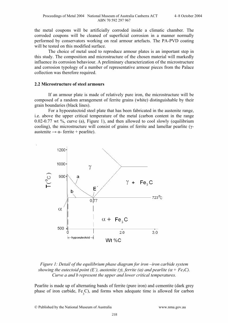
If an armour plate is made of relatively pure iron, the microstructure will be composed of a random arrangement of ferrite grains (white) distinguishable by their grain boundaries (black lines). For a hypoeutectoid steel plate that has been fabricated in the austenite range, i.e. above the upper critical temperature of the metal (carbon content in the range 0.02-0.77 wt %, curve (a), Figure 1), and then allowed to cool slowly (equilibrium cooling), the microstructure will consist of grains of ferrite and lamellar pearlite (γ-austenite → α- ferrite + pearlite).
Figure 1: Detail of the equilibrium phase diagram for iron –iron carbide system showing the eutectoid point (E’), austenite (γ), ferrite (α) and pearlite (α + Fe3C).
Curve a and b represent the upper and lower critical temperatures. Pearlite is made up of alternating bands of ferrite (pure iron) and cementite (dark grey phase of iron carbide, Fe
3C), and forms when adequate time is allowed for carbon
218

Proceedings of Metal 2004 National Museum of Australia Canberra ACT 4–8 October 2004 ABN 70 592 297 967
© Published by the National Museum of Australia www.nma.gov.au
present in solution (in prior austenite) to crystallise as iron carbide. Upon cooling from the austenite range, the first phase to form is pro-eutectoid ferrite. The morphology of the latter is partly determined by the cooling rate and the relative size of prior austenite grains. Slow cooling in air and small prior austenite grains favours the formation of equi-axed ferrite. In contrast, large prior austenite grains and rapid air-cooling allows for the formation of Widmanstätten ferrite. These grains assume acicular and/or wedge-shaped shaped structures (Garagnani et al, 1996; Bhadeshia, 1985). If the steel plate is forged below its upper critical temperature (curve (a), Figure 1), the ferrite grains obtained will be distorted. This occurs because ferrite crystals would have already been formed below the critical temperature (Williams, 1980). Another possible microstructure for steel occurs when an armour plate is given a ‘full quench’ that is, when the plate is cooled rapidly to ambient temperatures by dipping in cold water directly from forging temperatures. This is a case of non-equilibrium cooling. The iron-iron carbide equilibrium diagram given in Figure 1 will not be useful in describing the microstructure since iron carbide will not have had enough time to separate out of solution. The steel will transform at a lower temperature into a phase consisting of plate-like or needle-like grains of martensite. Martensite is exceedingly hard but unfortunately very brittle. Quenched armour would therefore not serve any good use on the battlefield. The armour craftsmen of the 15th century were quite knowledgeable of this fact and devised different routes to circumvent the problem (Williams, 2003). For the case of quenched steel, the material was subsequently subjected to a heat treatment or tempering. Tempering causes the non-equilibrium martensite grains to transform into ferrite and carbides. During heat treatment, carbides are dispersed evenly in a ferrite matrix and material toughness is enhanced at the expense of hardness. This technique was mastered in the southern cities of Germany, primarily Augsburg and Landshut. An alternative to the ‘full quench’ is the ‘interrupted quench’. Red hot metal is plunged in cold water (few seconds), taken out in air and allowed to cool for a few more seconds and is then reintroduced into cold water where it is allowed to continue cooling. Overall the cooling rate is less than that for a full quench and ferrite and pearlite phases form together with martensite. Another method involved varying the cooling rate of hot worked armour to obtain something in-between a full quench and equilibrium cooling. The resulting microstructure contained ferrite, pearlite as well as martensite. The latter process is known as slack–quenching and was performed by cooling armour in oil or molten lead. The cooling rate is intermediate between that following quenching in water and cooling in air (annealing) and can also be referred to as normalizing.
The presence of slag inclusions is a common occurrence in armour metal. Slag originates from impurities present in the iron ore. Hammer scale (iron oxides) from forging activity and the sand (silicates added to serve the purpose of flux during forge welding) also contribute to the volume fraction of slag in the finished product (Williams, 2003). Slag is a brittle glassy material containing iron silicate (fayalite). During hot forging, slag is plasticized and shaped into elongated stringers in a direction perpendicular to that of the direction of beating of the hammer (Williams, 2003).
219

Proceedings of Metal 2004 National Museum of Australia Canberra ACT 4–8 October 2004 ABN 70 592 297 967
© Published by the National Museum of Australia www.nma.gov.au
3. Methodology 3.1 Choice of Artefacts For this project, it was essential to select a number of artefacts that would represent the whole Palace collection. This proved very difficult to achieve since the collection is very heterogeneous (design, dating, provenance, functionality etc). Aware of this problem, we carried out a survey of the armour collection. The survey focused on dating and provenance, corrosion typology and past protective applications. On completion of the survey we were in a position to choose a small (10 pieces) but representative group of armour artefacts for further investigation. Table 1 lists and describes these artefacts.
Artefact Inventory No
Provenance Date General state
Upper right leg protection (tasset)
PA RC 29 N/a N/a Artefact is part of a tasset. The artefact is heavily corroded.
Left shoulder protection (pauldron)
PA RC 166
North Italian 1600-1650
Artefact is part of a pauldron. The artefact is heavily corroded. The artefact is decorated by a brass rivet motif.
Backplate PA 329 North Italian ca. 1570 Artefact is a complete armour piece. It is damaged on one side (a small section has been cut through the metal). Reticular corrosion occurs on the external horizontal surface.
Neck protection (gorget)
PA RC 25 North Italian ca. 1670 Artefact forms the back part of the gorget armour piece. The artefact is complete but is covered with a thin layer of corrosion. Original metal etching decoration is still visible under the corrosion layer.
Upper right leg protection (tasset)
PA RC 80 Probably German
N/a Artefact forms a complete tasset armour piece that is slightly corroded.
Protection of right the upper arm (cannon)
PA RC 20 North Italian ca. 1670 Artefact forms a complete armour piece and suffers from general corrosion. Original metal surface was decorated with etching. This decoration is still visible under the layers of corrosion.
Right shoulder protection (pauldron)
PA 317 North Italian ca. 1570 Artefact forms a complete armour piece. Corrosion occurs on the external horizontal surfaces.
Left shoulder protection (pauldron)
PA 316 North Italian ca. 1570 Artefact forms a complete armour piece. Corrosion occurs on the external horizontal surfaces.
220
Proceedings of Metal 2004 National Museum of Australia Canberra ACT 4–8 October 2004 ABN 70 592 297 967
© Published by the National Museum of Australia www.nma.gov.au
Full arm (left) comprising pauldron, upper and lower cannon and elbow piece.
PA RC 88 North Italian ca. 1620 Artefact made up of several armour pieces, which serve to protect the left arm of the wearer. Investigative work was carried out on the pauldron.
Right shoulder protection (pauldron)
PA RC 165
North Italian 1600-1650
Artefact is part of a pauldron. A thin layer of corrosion covers the artefact. The artefact is decorated by a brass rivet motif.
Table 1 – Inventory number, provenance and approx. dating of armour artefacts selected for further investigation. N/a means “ not available”
3.2 Sample Preparation Each armour piece was examined visually in order to identify a proper site for sampling. Fragment extraction was carried out in accordance to the following requirements:
(i) The site of sampling must be easily accessible. The cutting device is of a certain size and some space is required for maneuvering.
(ii) The fragment size is kept to a minimum (ca. 10 mm2
max.) (iii) Armour artefacts are complicated 3-dimensional objects comprising an
external and an internal surface. Where possible, the fragment is extracted from the interior of the armour piece
(iv) For the case of corroded armour pieces, fragments are preferably extracted from corroded areas.
(v) Sampling is performed in such a way that important features on the surface of the armour are not damaged nor lost (e.g. decoration - etching or embossing, loss of curved features etc…)
(vi) Sampling was carried out with the prior consent of the curator.
Fragments were cut out from the armour plate using a jeweller’s saw. Distilled
water was applied onto the fragment and surrounding metal during the extraction process so as to avoid overheating the metal which could alter the microstructure. Each fragment was attached to the bottom of a mould (25mL volume plastic cup) using a minimum amount of Superglue. Fragments were positioned in such a manner that permitted the armour plate from which the sample was extracted to be viewed in cross-section. Once fixed, fragments were embedded in an epoxy-based resin (Epoplast by Buehler). Liquid resin was slowly poured over the fragments to avoid trapping air bubbles and allowed to solidify overnight in a fume hood. Grinding of the polymer surface and embedded metal was carried out on a turntable using successively 100, 200, 300, 400 and 600-grade silicon carbide grinding paper. Grinding was performed in a direction parallel to the embedded metal section. Tap water was used as lubricant. For each grinding step, the exposed metal surface was cleaned thoroughly to remove traces of silicon carbide particles that detach from the grinding paper and remain stuck to the surface. Cleaning involved
221

Proceedings of Metal 2004 National Museum of Australia Canberra ACT 4–8 October 2004 ABN 70 592 297 967
© Published by the National Museum of Australia www.nma.gov.au
applying a layer of concentrated liquid surfactant (e.g. non-ionic Triton X-100) onto the exposed metal and surrounding polymer surface, dipping into hot running tap water for a few seconds, washing with an alcohol/methylated spirit mixture and drying rapidly with a heat gun (hair-dryer). Sections were then checked under a magnifying lens to evaluate the consistency and direction of the grinding marks before proceeding to finer grade paper. Polishing was carried out on a polishing turntable using 6-micron followed by 1-micron diamond paste. An alcohol-based lubricant (Buehler) was used for polishing. During polishing, the treated surface was counter rotated in the direction of motion of the turntable. This allows for homogenous polishing of the whole surface. On switching from six to one micron, the metal was washed thoroughly to remove the coarser particles. A final cleaning was performed following polishing with 1-micron diamond paste. When dealing with historic or archaeological metal containing slag inclusions and/or corrosion layers, it becomes relatively difficult to obtain a metallic surface that is completely free of scratch marks. Insisting with polishing is likely to induce further scratches. 3.3 Observation, etching and examination
Polished sections were examined optically using a metallographic microscope equipped a white light source. A preliminary observation was carried out prior to etching. Features such as slag inclusions, corrosion layers and corrosion pits are easily identifiable against the white unetched background. In comparison, an etched matrix may render the identification of these microstructural features more difficult. The polished metal was then etched chemically in 2% Nital-Picral solution (2% nitric acid in ethanol, containing a trace amount of picric acid; the latter is added to enhance the effect of the Nital etch; etching time < 5 seconds) and is followed by an alcohol rinse and drying in warm air. The etched samples were re-examined under the metallographic microscope. For the metal cross-section extracted from PA RC 165 (pauldron), Oberhoffer’s reagent (500mL distilled water, 500mL ethanol, 0.5g tin(II) chloride, 1g copper(II) chloride, 30g iron(III) chloride and 50mL nitric acid) was used as a second etchant. Not more than a few minutes were allowed to elapse between the final polishing step and etching. Longer times lead to the formation of a thin layer of iron oxide on the metallic surface that tends to slow down the etching process. This effect is not desirable when dealing with metal fragments covered with corrosion layers. A longer exposure to the etching solution is likely to cause dissolution of corrosion material, which will, in turn, stain the grains forming the microstructure. An estimate of the carbon content in ferrite-pearlite steel can be obtained from an evaluation of the ratio of dark and white areas in the photomicrograph. This can be carried out using an image analysis computer program. The software evaluates the ratio of black and white areas on a digitized microphotograph and calculates an approximate value for the concentration of carbon. Unfortunately this software was not available at the time of this study and we had to resort to an approximate estimate of the carbon content based on visual inspection of the microphotographs at low magnification.
222

Proceedings of Metal 2004 National Museum of Australia Canberra ACT 4–8 October 2004 ABN 70 592 297 967
© Published by the National Museum of Australia www.nma.gov.au
4. Results A description of the microstructure of armour elements is listed in Table 1. Microstructures are described starting with the simplest and proceeding to the more complex structures. Tasset (Inv. No. PA RC 29) and pauldron (Inv. No. PA RC 166)
(a)
(b)
(c)
Figure 2: (a) part of a tasset armour piece (PA RC 29) (b) photomicrograph showing etched area of sample extracted from artefact shown in (a). The microstructure consists of ferrite grains. Elongated slag inclusions run the length of the section. (c) part of a pauldron armour piece (PA RC 166). Enclosed area indicates the site of sampling.
Artefacts PA RC 29 (upper leg protection, Figure 2a) and PA RC 166 (shoulder protection, Figure 2c) form parts of armour pieces and both are heavily corroded. For PA RC 29, the sample fragment was extracted from the backside of the artefact. The microstructure comprises of ferrite grains and a large volume fraction of slag (Figure 2b). The abundance of slag inclusions suggests that this armour piece was manufactured from very poor quality metal. Artefact PA RC 166 exhibits the same microstructure. The armour piece and site of sampling are shown in Figure 2c.
Ferrite grains
Elongated slag
223

Proceedings of Metal 2004 National Museum of Australia Canberra ACT 4–8 October 2004 ABN 70 592 297 967
© Published by the National Museum of Australia www.nma.gov.au
Backplate (Inv. No. PA 329) and gorget (Inv. No. PA RC 25)
(a)
(b)
(c)
Figure 3: (a) backplate (PA 329) (b) photomicrograph showing etched area of sample extracted from backplate given in (a). Microstructure comprises of coarse ferrite grains (some acicular) and pearlite (c) part of a gorget (PA RC 25). Enclosed area indicated the site of sampling.
The backplate is a complete armour piece (Figure 3a). The sample was extracted from a damaged area of the armour piece. The microstructure consists of coarse ferrite grains surrounding islands of pearlite (Figure 3b). Widmanstätten ferrite plates having an acicular or wedge shaped structure are present in some areas (Garagnani et al 1996; Badeshia, 1985). The content of carbon in this hypoeutectoid steel is estimated at ca. 0.3-0.4-wt %. The ferrite and pearlite microstructure indicates that the plate was air cooled after fabrication. Artefact PA RC 25 is a part of the armour piece forming a gorget (neck protection). The plate is decorated by an etching motif. The decoration is still visible in spite of a thin layer of corrosion material that covers the whole artefact. The site of sample extraction is indicated in Figure 3c. The microstructure of this hypoeutectoid steel is the same as for the backplate except that this artefact has more elongated slag inclusions. The carbon content is estimated at ca. 0.1-0.2 wt %, slightly lower than that obtained for the backplate. The microstructure suggests that the armour plate was air cooled after fabrication.
Ferrite Pearlite
224

Proceedings of Metal 2004 National Museum of Australia Canberra ACT 4–8 October 2004 ABN 70 592 297 967
© Published by the National Museum of Australia www.nma.gov.au
Tasset (Inv. No. PA RC 80)
(a)
(b)
Figure 4: (a) tasset (PA RC 80) (b) photomicrograph showing etched area of sample extracted from tasset shown in (a). The microstructure is ferrite and pearlite with elongated slag inclusions. The ferrite grains are slightly distorted.
The artefact forms a whole armour piece (Figure 4a). A sample was extracted from the backside. The microstructure consists of coarse ferrite grains and pearlite. Some ferrite assumes a Widmanstätten structure (Figure 4b). The steel is a hypoeutectoid with a carbon content estimated at 0.1-0.2-wt %. Ferrite grains are slightly distorted indicating that the plate was subject to some amount of cold working (performed below curve (a) in Figure 1). The microstructure suggests that the artefact was air cooled after fabrication.
Ferrite
Pearlite
225

Proceedings of Metal 2004 National Museum of Australia Canberra ACT 4–8 October 2004 ABN 70 592 297 967
© Published by the National Museum of Australia www.nma.gov.au
Cannon (Inv. No. PA RC 20) and pauldron (Inv. No. PA 317)
(a)
(b)
(c)
Figure 5: (a) upper cannon (PA RC 20) (b) photomicrograph showing etched area of sample extracted from cannon given in (a). The microstructure comprises of ferrite and pearlite with slag inclusions. Corrosion layers are visible in light grey (c) pauldron (PA 317).
Artefact PA RC 20 (protection of the upper arm, Figure 5a) is decorated by an etching motif and suffers extensive corrosion attack. A fragment was extracted from a corroded area. The microstructure consists of fine-grained equi-axed ferrite grains (ca. 5-10 microns in diameter) and a small amount of pearlite (Figure 5b). The carbon content of this hypoeutectiod steel was estimated at 0.1-0.2-wt %. Elongated slag inclusions run the length of the cross-section. The metal cross-section is extensively corroded and in some places corrosion has penetrated deep within the metal. The microstructure indicates that the armour piece was left to cool in air after fabrication. Pauldron PA 317 (Figure 5c) exhibits a very similar microstructure to PA RC 20.
Corrosion layers
Fine ferrite and pearlite
226

Proceedings of Metal 2004 National Museum of Australia Canberra ACT 4–8 October 2004 ABN 70 592 297 967
© Published by the National Museum of Australia www.nma.gov.au
Pauldron (Inv. No. PA 316)
(a)
(b) Figure 6: (a) pauldron (PA 316) (b) photomicrograph showing etched area of sample extracted from (b). Microstructure showing ferrite, carbides and elongated slag inclusions.
A fragment was extracted from within the armour piece (Figure 6a). The microstructure consists of ferrite grains and patches of pearlite. This is a hypoeutectoid steel with a carbon content estimated at 0.2-0.3 wt %. When the section was examined at higher magnification, it was noted that pearlite was transformed into carbides (‘divorced’ pearlite). The lamellar nature of the pearlite was converted into irregularly shaped carbide stringers. Slag inclusions (circular and elongated morphology) are clearly identifiable from carbides in the photomicrograph (Figure 6b). This may have occurred as a result of sustained heating below the lower critical temperature (below curve (b), Figure 1). Perhaps the armour piece was repaired at some stage.
Slag
Irregularly shaped carbides
227

Proceedings of Metal 2004 National Museum of Australia Canberra ACT 4–8 October 2004 ABN 70 592 297 967
© Published by the National Museum of Australia www.nma.gov.au
Pauldron (Inv. No. PA RC 88)
(a)
(b) Figure 7: (a) full arm comprising of a pauldron, upper and lower cannon and elbow piece (PA RC 88) (b) photomicrograph of sample extracted from (a). The microstructure is primarily pearlitic. A large corrosion crack has developed. A ferrite band lines the corrosion crack.
A sample was extracted from inside the pauldron (Figure 7a). The microstructure is predominantly pearlitic (near eutectoid steel, carbon content 0.6-0.7 wt %) with a band of ferrite running through the middle part of the metal section. The ferrite grains line a large corrosion crack (Figure 7b). The corrosion crack seems to be following elongated slag inclusions (galvanic effect). It is very probable that the crack had developed at a weld zone, since forge welding is likely to leave a row of slag inclusions trapped along the weld line (Williams, 2003). The ferrite phase formed along the crack further supports this hypothesis. In fact, the formation of the ferrite probably resulted from the decarburization (loss of carbon) of the metal in the weld region.
Pearlite
Ferrite Corrosion crack
228

Proceedings of Metal 2004 National Museum of Australia Canberra ACT 4–8 October 2004 ABN 70 592 297 967
© Published by the National Museum of Australia www.nma.gov.au
Pauldron (Inv. No. PA 165)
(a)
(b)
Figure 8: (a) part of a pauldron (PA RC 165) (b) photomicrograph showing etched area of sample extracted from (a). Phosphorus rich iron shows in white while phosphorus depleted zones show in dark grey.
The plate formed part of a pauldron that was decorated by brass rivets (Figure 8a). The microstructure consists of ferrite grains and slag. Furthermore, the Nital etch incurs a water shimmer appearance on some of the ferrite grains. This effect is referred to as ghosting and occurs in case of irons containing ca. 0.1-0.5% phosphorus (Stewart et al, 2000). Nital etches phosphorus rich iron zones to a lesser extent than pure ferrite leading to surface relief effects. The ghost microstructure is revealed by slight adjustments of the fine focus of the optical microscope (Stewart et al, 2000). In order to confirm the presence of phosphoric iron, Oberhoffer’s reagent was applied subsequent to Nital etchant. The reagent deposits copper on the surface of pure ferrite grains. This causes the grains to appear dark under the optical microscope. Less copper is deposited in regions rich in phosphorus so that these appear bright (Stewart at al, 2000). A photomicrograph of the metal section treated with Oberhoffer’s reagent is given in Figure 8b.
Phosphorus rich ferrite
Phosphorus depleted ferrite
Slag
229
Proceedings of Metal 2004 National Museum of Australia Canberra ACT 4–8 October 2004 ABN 70 592 297 967
© Published by the National Museum of Australia www.nma.gov.au
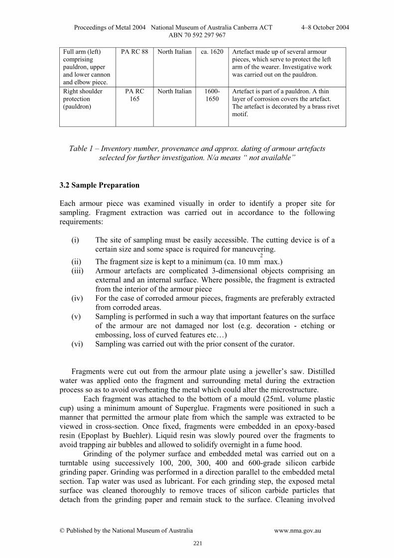
5. Discussion Table 2 summarizes the general microstructural features of the armour pieces investigated.
Armour piece
Inv No. Microstructure slag Wt % carbon
Cooling rate
Comments
Tasset PA RC 29 Ferrite +++ N/a Air cooled Pauldron PA RC
166 Ferrite +++ N/a Air cooled
Backplate PA 329 Ferrite and pearlite
+ 0.2-0.3 Rapid air cooling
Widmanstätten ferrite
Gorget PA RC 25 Ferrite and pearlite
++ 0.1-0.2 Rapid air cooling
Widmansttäten ferrite
Tasset PA RC 80 Distorted ferrite and pearlite
++ 0.1-0.2 Rapid air cooling
Widmanstätten ferrite.
Cannon PA RC 20 Ferrite and pearlite
+ 0.1-0.2 Air cooled Equi-axed ferrite
Pauldron PA 317 Ferrite and pearlite
+ 0.1-0.2 Air cooled Equi-axed ferrite
Pauldron PA 316 Ferrite and pearlite
+ 0.1-0.2 Air cooled ‘Divorced’ pearlite
Pauldron (full arm)
PA RC 88 Ferrite and Pearlite
++ 0.6-0.7 Air cooled Pearlitic steel with ferrite lining a corrosion crack
Pauldron PA RC 165
Ferrite with ghost microstructure
+++ N/a Air cooled iron containing phosphorus in the range 0.1-0.5 wt%
Table 2- Inventory number, microstructure, wt % carbon and cooling rate. Low (+) medium (++) and high (+++) slag content. N/a means “not available”.
Slag inclusions were present in all the armour plates examined. This indicates
that the metal (steel or wrought iron) utilized in the manufacture of these armour plates was produced from its ore via pre-modern techniques such as the Bloomery hearth. Wrought iron produced from the reduction of cast iron, and steel obtained directly from the reduction of the ore allowed for an amount of slag to remain in the finished bloom (Williams, 2003). Hence the armour pieces used in this study could be authenticated from the presence of slag. Furthermore, the elongated nature of slag suggests that these armour plates were forged into shape at relatively high temperatures (Williams, 2003). Out of ten artefacts examined, three pieces were made of wrought iron (ferrite) and seven were made in steel. As indicated in Table 2, the highest amount of slag was obtained in the wrought iron armour fragments. Excessive quantities of slag cause the metal to become brittle (Williams, 2003). The high amount of slag obtained in wrought iron artefacts indicates armour of lower quality. For steel armour, the carbon content varies within the range 0.1 to 0.3 wt %. The metal utilized in the production of these artefacts would classify as low carbon steel. An exceptional case is artefact PA RC 88 which is a higher carbon steel containing 0.6-0.7wt % carbon. The size and shape of the ferrite grains vary considerably from one steel to another. Artefacts PA RC 20 and PA 317 exhibit fairly
230
Proceedings of Metal 2004 National Museum of Australia Canberra ACT 4–8 October 2004 ABN 70 592 297 967
© Published by the National Museum of Australia www.nma.gov.au
fine equi-axed grains (5 - 10µm) while PA RC 25, PA 329 and PA RC 80 show coarse ferrite grains, some featuring an acicular shape. The latter microstructure was first described in meteoric iron by Widmanstätten (Tylecote, 1992). The acicular ferrite grains tend to isolate pearlite into separate patches, so that both the strength and toughness of the final material are unevenly distributed. Such a structure therefore renders the steel plate weak and brittle (Garagnani et al 1996; R.A. Higgins, 1993). Williams describes armour with this type of microstructure as being of inferior quality. The armour pieces were probably maintained at very high temperatures (allowing the formation of large austenite grains) and then cooled relatively rapidly in air. Armour piece PA RC 165 was manufactured from a phosphoric iron. This was confirmed by the Oberhoffer’s reagent. The microstructure consists of bands of phosphorus-rich and phosphorus-depleted zones. For an iron that contains phosphorus in the concentration range (0.1-0.5) wt %, a temperature domain exists where austenite and ferrite co-exist (900-1400
oC). The solubility of P in austenite is lower
than in ferrite. Thus, if the metal is maintained in the two phase region for a sufficiently long enough time, regions of low and high P will appear, corresponding to prior austenite and ferrite zones respectively. The armour plate section revealed a banded microstructure with regions of high (white) and low (dark) phosphorus zones. This banding arrangement was encountered in a number of archaeological and historic artefacts examined by Vega. (Vega et al, 2002). The banded arrangement (phosphorus rich zones alternating with phosphorus depleted zones) was attributed to forging activity. Williams has performed metallographic examination of a large number of armour suits and separate armour pieces. He argues that although phosphoric irons are frequently found in archeological irons, they are seldom found in armour metal (Williams, 2003). Phosphorus renders the steel ‘cold short’ that is when cold worked the resulting material has inferior mechanical properties and is relatively brittle (Stewart, 2000). A phosphorus-rich armour plate would therefore not serve much use on the battlefield and it seems that the armourers of the time were aware of this fact. It is therefore very likely that this particular armour piece was produced from recycled material (iron objects other than armour), or from an iron billet that contained phosphorus. Phosphorus is commonly found in iron ore but might also find its way into iron from the fuel during the reduction process. Whatever the case, the armourer or blacksmith was probably unaware of the poor quality of the metal that was used. Williams conducted an extensive study of the metallurgy of European armour. Italian armour manufactured before the year 1510 was often subject to heat treatment. In an attempt to harden the metal slack quenching was often used. This practice seems to have been stopped abruptly shortly afterwards. This applies to both good quality armour as well as field armour. Williams attributes this sudden change to the introduction of fire gilding (Williams, 2003). Out of six Italian steel armour plates investigated in this study, all were produced after 1510 and none showed any sign of quenching. Fast cooling would have provoked the formation of martensite, a phase that was not detected in any of the samples examined. This is in agreement with the general trend observed by Williams. However, given the small number of armour artefacts examined, a more comprehensive study involving many more pieces would have to be performed in order to draw more definite conclusions.
231

Proceedings of Metal 2004 National Museum of Australia Canberra ACT 4–8 October 2004 ABN 70 592 297 967
© Published by the National Museum of Australia www.nma.gov.au
6. Conclusion
The metallurgy of several armour pieces from the Palace Armoury collection was examined for the first time in the collection’s history. The metallurgy is quite heterogeneous. Of the ten armour elements investigated, three pieces were made in wrought iron, six classified as low carbon steels and one was made of high carbon steel. One of the wrought iron armour pieces was made of a phosphoric iron, an unusual material for such artefacts. All the armour pieces were forged into shape as evidenced by the elongated morphology of the slag inclusions. None of the artefacts seemed to have been quenched (full or slack) in order to obtain steel of superior strength and quality. From this preliminary investigation, we have concluded that the best material for use in the preparation of coupons will be plain low carbon steel with minimal alloying elements. Acknowledgments Heritage Malta and the Palace Armoury Collection for allowing us to sample the armour artefacts Cost Action G8 for funding a short-term scientific mission (STSM) to the Wallace Collection in London. The Wallace Collection for hosting the STSM. Mr. Stephen C. Spiteri for helping out in the dating and provenance of the armour pieces The Malta Centre for Restoration for supporting this work References Bhadeshia H. K. D. H. (1985) Diffusional formation of ferrite in iron and its alloys Progress in Material Science, 29, 321-386. Bomomi, S., Martini, C., Poli G. and Prandstraller, D. (2003) Modernity of Early Metallurgy: Studies on an Etruscan Anthropomorphic Bronze Handle, International conference, Archaeometallurgy in Europe, Milan, Italy September 24-26
th, 467-472.
Chetcuti, D., Buhagiar, A., Schembri, P. J. and Ventura, F. (1992) The Climate of the Maltese Islands: A Review (University Press, Malta). Garagnani, G. L., Zucchi, F., Tommesani L. and Brunoro, G. (1996) Metallurgical investigations on 16
th –17
th century iron armours from the Museo Nazionale of
Ravenna, Science and Technology for Cultural Heritage 5 (2), 83-94. Higgins, R. A. (1993) Engineering Metallurgy – Volume 1, Applied Physical Metallurgy (Edward Arnold, UK).
232

Proceedings of Metal 2004 National Museum of Australia Canberra ACT 4–8 October 2004 ABN 70 592 297 967
© Published by the National Museum of Australia www.nma.gov.au
Spiteri, S. C. (1999) The Palace Armoury, A study of a Military Storehouse of the Knights of the Order of St. John (Print Services Ltd, Malta). Stewart, J. W., Charles J. A. and Wallach, E. R. (2000) Iron –phosphorus- carbon system Part 1 – Mechanical properties of low carbon iron-phosphorus alloys, Material Science and Technology, 16, 275-282. Stewart, J. W., Charles J. A. and Wallach, E. R. (2000) Iron –phosphorus- carbon system Part 2 – Metallographic behaviour of Oberhoffer’s reagent, Material Science and Technology, 16, 283-290. Stewart, J. W., Charles, J. A. and Wallach, E. R. (2000) Iron –phosphorus- carbon system Part 3 – Metallography of low carbon iron-phosphorus alloys, Material Science and Technology, 16, 291-303. Tylecote, R. F. (1992) A History of Metallurgy 2nd
edition, (Institute of Materials, UK). Vega E., Dillmann P., Lheritier M., Fluzin P., Crew P. and Benoit P. (2003) Forging of phosphoric iron. An analytical and experimental approach, International conference, Archaeometallurgy in Europe, Milan, Italy. September 24-26th,
AIM 337-
346 Williams A. (1980) To what extent can forgeries be detected by metallurgical analysis, A study of some helmets, Institut Suisse d’Armes Anciennes , Rapport 3 and 4, Grandson 61. Williams A. (2003) The Knight and the Blast Furnace, A History of the Metallurgy of Armour in the Middle Ages and the Early Modern Period (Lieden, Netherlands).
233


![WHFRPG [Eng] - Old World Armoury](https://img.pdfslide.net/doc/110x75/5571f85c49795991698d3f0b/whfrpg-eng-old-world-armoury.jpg)