Embed Size (px)
Citation preview

8/19/2019 Metalurgi pengecoran
http://slidepdf.com/reader/full/metalurgi-pengecoran 1/49
Kalpakjian • Schmid Manufacturing Engineering and Technology © 2001 Prentice-Hall Page 11-1
PROSES PENGECORAN

8/19/2019 Metalurgi pengecoran
http://slidepdf.com/reader/full/metalurgi-pengecoran 2/49
Kalpakjian • Schmid Manufacturing Engineering and Technology © 2001 Prentice-Hall Page 11-2
Introduction
Casting
Penuangan logam cair ke cetakan sesuai dengan bentuk yang diinginkan. Setelah penuangan,dilanjutkan dengan proses pembekuan padacetakan dan benda dikeluarkan dari cetakan
8/19/2019 Metalurgi pengecoran
http://slidepdf.com/reader/full/metalurgi-pengecoran 3/49
Kalpakjian • Schmid Manufacturing Engineering and Technology © 2001 Prentice-Hall Page 11-3
Introduction
-Dapat digunakan untuk menghasilkan geometri yangkompleks baik internal maupun eksternal
- Beberapa proses pengecoran dapat mengasilkankomponen net shape (tidak memerlukan proses
pengerjaan manufaktur lanjutan)- Dapat menghasilkan komponen yang sangat besar (berat
lebih dari 100 ton)
- Dapat digunakan untuk berbagai jenis logam yang dapat
dipanaskan sampai fasa cair- Beberapa tipe proses casting cocok untuk mass
production

8/19/2019 Metalurgi pengecoran
http://slidepdf.com/reader/full/metalurgi-pengecoran 4/49
Kalpakjian • Schmid Manufacturing Engineering and Technology © 2001 Prentice-Hall Page 11-4
RingkasanProses – proses
Pengecoran
TABLE 11.1
Process Advantages LimitationsSand Almost any metal cast; no limit
to size, shape or weight; low
tooling cost.
Some finishing required;
somewhat coarse finis h; wide
tolerances.
Shell mold Good dimensional accuracy and
surface finish; high production
rate.
Part size limited; expensive
patterns and equipment
required.
Expendable pattern Most metals cast with no limit
to size; complex s hapes
Patterns have low strength and
can be costly for low quantities
Plaster mold Intricate shapes; good
dimensional accu- racy and
finish; low porosity.
Limited to nonferrous metals;
limited size and volume of
production; mold making time
relatively long.
Ceramic mold Intricate shapes ; clos e
tolerance parts; good surface
finish.
Limited size.
Investment Intricate shapes; excellent
surface finish and accuracy;
almost any metal cast.
Part size limited; expensive
patterns, molds, and labor.
Permanent mold Good surface finish and
dimensional accuracy; low
porosity; high production rate.
High mold cost; limited shape
and intricacy; not suitable for
high-melting-point metals.
Die Excellent dimensional accuracyand surface finish; high
production rate.
Die cost is high; part sizelimited; usually limited to
nonferrous metals; long lead
time.
Centrifugal Large cylindrical parts with
good quality; high production
rate.
Equipment is expensive; part
shape limited.

8/19/2019 Metalurgi pengecoran
http://slidepdf.com/reader/full/metalurgi-pengecoran 5/49
Kalpakjian • Schmid Manufacturing Engineering and Technology © 2001 Prentice-Hall Page 11-5
Contoh komponen hasil pengecoran
Crank handle setelah castingpada beberapa area dilakukanpemesinan dan perakitan
C-clamps formed by casting(left) and machining (right)
Complex part formed by castingCourtesy of Toth Industries

8/19/2019 Metalurgi pengecoran
http://slidepdf.com/reader/full/metalurgi-pengecoran 6/49
Kalpakjian • Schmid Manufacturing Engineering and Technology © 2001 Prentice-Hall Page 11-6
Contoh produk hasilpengecoran
Figure 11.2 Typical gray-iron castings used inautomobiles, includingtransmission valve body(left) and hub rotor withdisk-brake cylinder (front).
Source: Courtesy of CentralFoundry Division of GeneralMotors Corporation.
Figure 11.3 A casttransmission housing.

8/19/2019 Metalurgi pengecoran
http://slidepdf.com/reader/full/metalurgi-pengecoran 7/49
Kalpakjian • Schmid Manufacturing Engineering and Technology © 2001 Prentice-Hall Page 11-7
Contoh : Die-Casting
(a) (b)
Figure 11.1 (a) The Polaroid PDC-2000 digital camera with a AZ91D die-cast, high puritymagnesium case. (b) Two-piece Polaroid camera case made by the hot-chamber die casting
process. Source: Courtesy of Polaroid Corporation and Chicago White Metal Casting, Inc.

8/19/2019 Metalurgi pengecoran
http://slidepdf.com/reader/full/metalurgi-pengecoran 8/49
Kalpakjian • Schmid Manufacturing Engineering and Technology © 2001 Prentice-Hall Page 11-8
Karakteristik Umum Proses Pengecoran
TABLE 11.2
Typical Weig ht (kg)
Typical
surface Section thic kness (mm)
Process
materials
cast Minimum Maximum
finish
(mm, R a) Porosity*
Shape
complexity*
Dimensional
accuracy* Minimum Maximum
Sand All 0.05 No limit 5-25 4 1-2 3 3 No limit
Shell All 0.05 100+ 1-3 4 2-3 2 2 --
Expendable
mold
pattern All 0.05 No limit 5-20 4 1 2 2 No limit
Plaster
mold
Nonferrous
(Al, Mg, Zn,
Cu) 0.05 50+ 1-2 3 1-2 2 1 --
Investment
All
(High melting
pt.) 0.005 100+ 1-3 3 1 1 1 75
Permanent
mold All 0.5 300 2-3 2-3 3-4 1 2 50
Die
Nonferrous
(Al, Mg, Zn,
Cu) <0.05 50 1-2 1-2 3-4 1 0.5 12
Centrifugal All -- 5000+ 2-10 1-2 3-4 3 2 100
*Relative rating: 1 best, 5 worst.
Note : These ratings are only general; significant variations can occur, depending on the methods used.

8/19/2019 Metalurgi pengecoran
http://slidepdf.com/reader/full/metalurgi-pengecoran 9/49
Kalpakjian • Schmid Manufacturing Engineering and Technology © 2001 Prentice-Hall Page 11-9
Persyaratan:
- Rongga cetakan sesuai dengan bentuk dan ukuran yangdiinginkan
-Proses pencairan untuk menghasilkan logam cair
- Proses penuangan untuk mengantarkan logam cair kecetakan
- Proses kontrol pembekuan untuk mencegah cacat
-Melepaskan produk dan cetakan
- Pembersihan, finishing dan inspeksi
Hal penting dalam pengecoran

8/19/2019 Metalurgi pengecoran
http://slidepdf.com/reader/full/metalurgi-pengecoran 10/49
Kalpakjian • Schmid Manufacturing Engineering and Technology © 2001 Prentice-Hall Page 11-10
Logam murni dan paduanLovgam munri membeku pada konstan temperatur dan paduan
membeku pada range temperatur

8/19/2019 Metalurgi pengecoran
http://slidepdf.com/reader/full/metalurgi-pengecoran 11/49
Kalpakjian • Schmid Manufacturing Engineering and Technology © 2001 Prentice-Hall Page 11-11
Proses pembekuan
A nucleating agent (inoculant) adalah senyawa yangberfungsi sebagai tempat nukleasi butir agar prosespengintian terbentuk pada waktu yang bersamaan di
seluruh bagian
8/19/2019 Metalurgi pengecoran
http://slidepdf.com/reader/full/metalurgi-pengecoran 12/49
Kalpakjian • Schmid Manufacturing Engineering and Technology © 2001 Prentice-Hall Page 11-12
Laju pendinginan
Rapid cooling cenderung menghasilkan butirequiaxed (bulat)
Slow cooling cenderung menghasilkan butirkolumnar (memanjang) yang tumbuh denganarah ke bagian tengah

8/19/2019 Metalurgi pengecoran
http://slidepdf.com/reader/full/metalurgi-pengecoran 13/49
Kalpakjian • Schmid Manufacturing Engineering and Technology © 2001 Prentice-Hall Page 11-13
Pembekuan logam
Dendrites
Tree-like structures that form during the solidification of alloys
Slow cooling rates produce dendrites with larger branch spacing;faster cooling rates produce finer spacing; very fast cooling rates produce no dendrites or grains

8/19/2019 Metalurgi pengecoran
http://slidepdf.com/reader/full/metalurgi-pengecoran 14/49
Kalpakjian • Schmid Manufacturing Engineering and Technology © 2001 Prentice-Hall Page 11-14
Istilah dalam Casting
FlaskThe box containing the mold
Cope
The top half of any part of a 2-part mold
Drag
The bottom half of any part of a 2-part mold
Core
A shape inserted into the mold to form internal cavities
Core Print
A region used to support the core

8/19/2019 Metalurgi pengecoran
http://slidepdf.com/reader/full/metalurgi-pengecoran 15/49
Kalpakjian • Schmid Manufacturing Engineering and Technology © 2001 Prentice-Hall Page 11-15
Istilah dalam Casting (lanjutan)
Mold Cavity
The hollow mold area in which metal solidifies into the part
Riser
An extra cavity to store additional metal to prevent shrinkage
Gating System
Channels used to deliver metal into the mold cavity
Pouring Cup
The part of the gating system that receives poured metal
Sprue
Vertical channel
Runners
Horizontal channels

8/19/2019 Metalurgi pengecoran
http://slidepdf.com/reader/full/metalurgi-pengecoran 16/49
Kalpakjian • Schmid Manufacturing Engineering and Technology © 2001 Prentice-Hall Page 11-16
Istilah dalam Casting (lanjutan)
Parting Line / Parting Surface
Interface that separates the cope and drag of a 2-partmold
DraftTaper on a pattern or casting that allows removal fromthe mold
Core Box
Mold or die used to produce coresCasting
The process and product of solidifying metal in a mold

8/19/2019 Metalurgi pengecoran
http://slidepdf.com/reader/full/metalurgi-pengecoran 17/49
Kalpakjian • Schmid Manufacturing Engineering and Technology © 2001 Prentice-Hall Page 11-17
Cetakan Pasir
Figure 11.4 Schematic illustration of a sand mold, showing various features.

8/19/2019 Metalurgi pengecoran
http://slidepdf.com/reader/full/metalurgi-pengecoran 18/49
Kalpakjian • Schmid Manufacturing Engineering and Technology © 2001 Prentice-Hall Page 11-18
Fungsi pada cetakan
• Vents sebagai pembuangan udara untuk mengeluarkan gas yang dihasilkanpada saat logam cair masuk dan kontakdengan cetakan.
•
Risers menahan dan men-supply logamcair agar tidak terjadi penyusutan selamaproses pembekuan
• Gates didesain untuk mencegah
kontaminan yang dapat masuk ke ronggacetakan

8/19/2019 Metalurgi pengecoran
http://slidepdf.com/reader/full/metalurgi-pengecoran 19/49
Kalpakjian • Schmid Manufacturing Engineering and Technology © 2001 Prentice-Hall Page 11-19
Figure 11.5 Outline of production steps in a typical sand-casting operation.
Tahapan Sand Casting

8/19/2019 Metalurgi pengecoran
http://slidepdf.com/reader/full/metalurgi-pengecoran 20/49
Kalpakjian • Schmid Manufacturing Engineering and Technology © 2001 Prentice-Hall Page 11-20
Karakteristik material untukpola/cetakan
TABLE 11.3
Ratinga
Characteristic Wood Aluminum Steel Plastic Cast iron
Machinability E G F G G
Wear resistance P G E F E
Strength F G E G GWeightb E G P G P
Repairability E P G F G
Resistance to:
Corrosionc E E P E P
Swellingc P E E E E
aE, Excellent; G, good; F, fair; P, poor.
bAs a factor in operator fatigue.
cBy water.
Source : D.C. Ekey and W.R. Winter, Introduction to Foundry Technology. New York.
McGraw-Hill, 1958.

8/19/2019 Metalurgi pengecoran
http://slidepdf.com/reader/full/metalurgi-pengecoran 21/49
Kalpakjian • Schmid Manufacturing Engineering and Technology © 2001 Prentice-Hall Page 11-21
Patterns Untuk SandCasting
Figure 11.6 A typical metalmatch-plate pattern used insand casting.
Figure 11.7 Taper on patterns forease of removal from the sand mold.

8/19/2019 Metalurgi pengecoran
http://slidepdf.com/reader/full/metalurgi-pengecoran 22/49
Kalpakjian • Schmid Manufacturing Engineering and Technology © 2001 Prentice-Hall Page 11-22
Examples of Sand Cores and Chaplets
Figure 11.8 Examples of sand cores showing core prints and chaplets to support cores.

8/19/2019 Metalurgi pengecoran
http://slidepdf.com/reader/full/metalurgi-pengecoran 23/49
Kalpakjian • Schmid Manufacturing Engineering and Technology © 2001 Prentice-Hall Page 11-23
Squeeze Heads
Figure 11.9 Various designs
of squeeze heads for moldmaking: (a) conventionalflat head; (b) profile head;(c) equalizing squeeze
pistons; and (d) flexiblediaphragm. Source: ©Institute of BritishFoundrymen. Used with
permission.
8/19/2019 Metalurgi pengecoran
http://slidepdf.com/reader/full/metalurgi-pengecoran 24/49
Kalpakjian • Schmid Manufacturing Engineering and Technology © 2001 Prentice-Hall Page 11-24
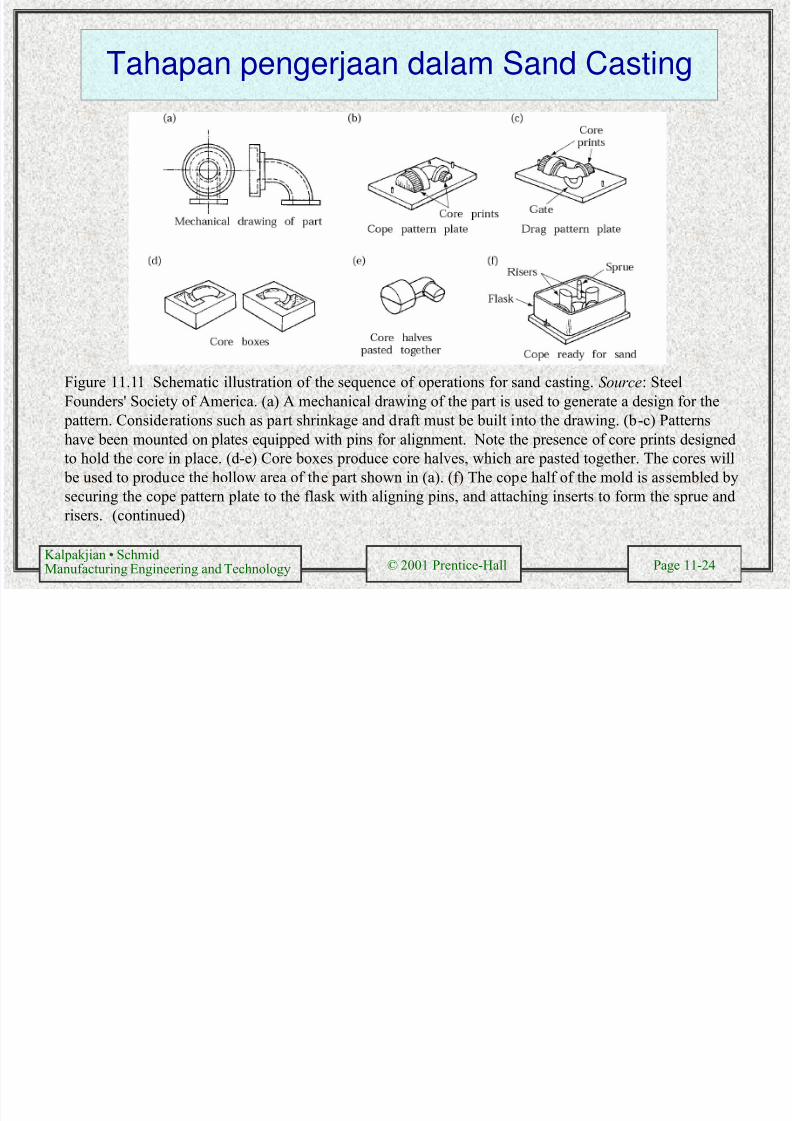
Tahapan pengerjaan dalam Sand Casting
Figure 11.11 Schematic illustration of the sequence of operations for sand casting. Source: Steel
Founders' Society of America. (a) A mechanical drawing of the part is used to generate a design for the
pattern. Considerations such as part shrinkage and draft must be built into the drawing. (b-c) Patternshave been mounted on plates equipped with pins for alignment. Note the presence of core prints designed
to hold the core in place. (d-e) Core boxes produce core halves, which are pasted together. The cores will
be used to produce the hollow area of the part shown in (a). (f) The cope half of the mold is assembled by
securing the cope pattern plate to the flask with aligning pins, and attaching inserts to form the sprue and
risers. (continued)

8/19/2019 Metalurgi pengecoran
http://slidepdf.com/reader/full/metalurgi-pengecoran 25/49
Kalpakjian • Schmid Manufacturing Engineering and Technology © 2001 Prentice-Hall Page 11-25
Figure 11.11 (g) The flask is rammed with sand and the plate and inserts are removed. (g) The drag half is produced in a similar manner, with the pattern inserted. A bottom board is placed below the drag and alignedwith pins. (i) The pattern, flask, and bottom board are inverted, and the pattern is withdrawn, leaving theappropriate imprint. (j) The core is set in place within the drag cavity. (k) The mold is closed by placing thecope on top of the drag and buoyant forces in the liquid, which might lift the cope. (l) After the metal solidifies,the casting is removed from the mold. (m) The sprue and risers are cut off and recycled and the casting iscleaned, inspected, and heat treated (when necessary).
Tahapan pengerjaan Sand Casting (lanjutan)
8/19/2019 Metalurgi pengecoran
http://slidepdf.com/reader/full/metalurgi-pengecoran 26/49
Kalpakjian • Schmid Manufacturing Engineering and Technology © 2001 Prentice-Hall Page 11-26
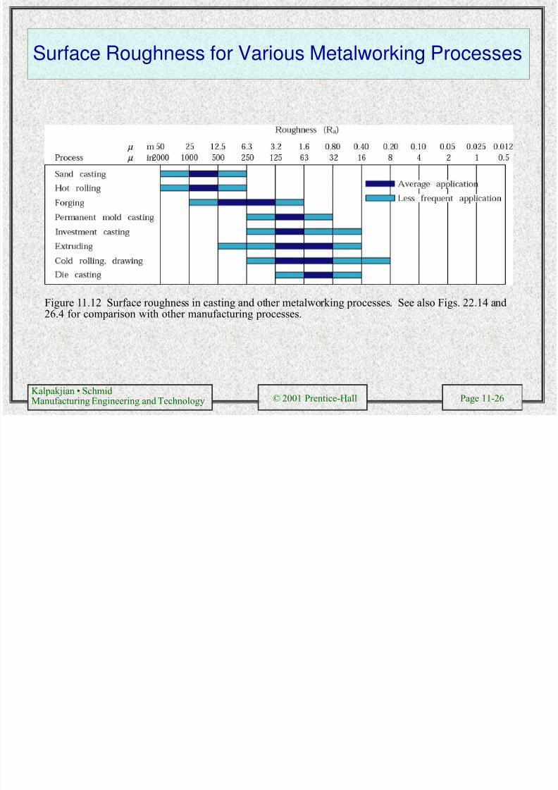
Surface Roughness for Various Metalworking Processes
Figure 11.12 Surface roughness in casting and other metalworking processes. See also Figs. 22.14 and26.4 for comparison with other manufacturing processes.

8/19/2019 Metalurgi pengecoran
http://slidepdf.com/reader/full/metalurgi-pengecoran 27/49
Kalpakjian • Schmid Manufacturing Engineering and Technology © 2001 Prentice-Hall Page 11-27
Ceramic Molds
Figure 11.16 Sequence of operations in
making a ceramic mold. Source: Metals Handbook , vol. 5, 8th ed.
Figure 11.17 A typical ceramicmold (Shaw process) for castingsteel dies used in hot forging.Source: Metals Handbook , vol.5, 8th ed.
Figure 11 18

8/19/2019 Metalurgi pengecoran
http://slidepdf.com/reader/full/metalurgi-pengecoran 28/49
Kalpakjian • Schmid Manufacturing Engineering and Technology © 2001 Prentice-Hall Page 11-28
Figure 11.18Schematicillustration ofinvestmentcasting, (lost-wax process).Castings by this
method can bemade with veryfine detail andfrom a variety ofmetals. Source:Steel Founders'Society ofAmerica.
InvestmentCasting
• Prosesinvestmentcasting disebut
juga dengan lost-
wax process
• pattern dibuatdari wax atauplastic sepertipolystyrene

8/19/2019 Metalurgi pengecoran
http://slidepdf.com/reader/full/metalurgi-pengecoran 29/49
Kalpakjian • Schmid Manufacturing Engineering and Technology © 2001 Prentice-Hall Page 11-29
Investment Casting of a Rotor
Figure 11.19 Investment casting of an integrally cast rotor for a gas turbine. (a) Wax pattern assembly.(b) Ceramic shell around wax pattern. (c) Wax is melted out and the mold is filled, under a vacuum,with molten superalloy. (d) The cast rotor, produced to net or near-net shape. Source: HowmetCorporation.

8/19/2019 Metalurgi pengecoran
http://slidepdf.com/reader/full/metalurgi-pengecoran 30/49
Kalpakjian • Schmid Manufacturing Engineering and Technology © 2001 Prentice-Hall Page 11-30
Investment and Conventionally Cast Rotors
Figure 11.20 Cross-section andmicrostructure of tworotors: (top)investment-cast;(bottom) conventionallycast. Source: Advanced
Materials and Processes, October1990, p. 25 ASMInternational

8/19/2019 Metalurgi pengecoran
http://slidepdf.com/reader/full/metalurgi-pengecoran 31/49
Kalpakjian • Schmid Manufacturing Engineering and Technology © 2001 Prentice-Hall Page 11-31
Vacuum-Casting Process
Figure 11.21 Schematic illustration of the vacuum-casting process. Note that the mold has a bottom gate. (a) Before and (b) after immersion of the mold into the molten metal. Source:From R. Blackburn, "Vacuum Casting Goes Commercial," Advanced Materials and Processes,February 1990, p. 18. ASM International.

8/19/2019 Metalurgi pengecoran
http://slidepdf.com/reader/full/metalurgi-pengecoran 32/49
Kalpakjian • Schmid Manufacturing Engineering and Technology © 2001 Prentice-Hall Page 11-32
Pressure Casting
Figure 11.22 (a) The bottom-pressure casting process utilizes graphite molds for the production of steelrailroad wheels. Source: The Griffin Wheel Division of Amsted Industries Incorporated. (b) Gravity-
pouring method of casting a railroad wheel. Note that the pouring basin also serves as a riser. Railroadwheels can also be manufactured by forging.

8/19/2019 Metalurgi pengecoran
http://slidepdf.com/reader/full/metalurgi-pengecoran 33/49
Kalpakjian • Schmid Manufacturing Engineering and Technology © 2001 Prentice-Hall Page 11-33
Hot- and Cold-Chamber Die-Casting
Figure 11.23 (a) Schematic illustration of the hot-chamber die-casting process. (b) Schematicillustration of the cold-chamber die-casting process. Source: Courtesy of Foundry Management andTechnology.
(a) (b)

8/19/2019 Metalurgi pengecoran
http://slidepdf.com/reader/full/metalurgi-pengecoran 34/49
Kalpakjian • Schmid Manufacturing Engineering and Technology © 2001 Prentice-Hall Page 11-34
Cold-Chamber Die-Casting Machine
(a)
Figure 11.24 (a) Schematic illustration of a cold-chamber die-casting machine.
These machines are large compared to the size of the casting because large forces arerequired to keep the two halves of the dies closed.

8/19/2019 Metalurgi pengecoran
http://slidepdf.com/reader/full/metalurgi-pengecoran 35/49
Kalpakjian • Schmid Manufacturing Engineering and Technology © 2001 Prentice-Hall Page 11-35
Figure 11.24 (b) 800-ton hot-chamber die-casting machine, DAM 8005 (madein Germany in 1998). This is the largest hot-chamber machine in the worldand costs about $1.25 million.
(b)
Hot-Chamber Die-Casting Machine

8/19/2019 Metalurgi pengecoran
http://slidepdf.com/reader/full/metalurgi-pengecoran 36/49
Kalpakjian • Schmid Manufacturing Engineering and Technology © 2001 Prentice-Hall Page 11-36
Die-Casting Die Cavities
Figure 11.25 Various types of cavities in a die-casting die. Source: Courtesy ofAmerican Die Casting Institute.
Figure 11.26 Examples ofcast-in- place inserts in diecasting. (a) Knurled
bushings. (b) Groovedthreaded rod.
Properties and Typical Applications of

8/19/2019 Metalurgi pengecoran
http://slidepdf.com/reader/full/metalurgi-pengecoran 37/49
Kalpakjian • Schmid Manufacturing Engineering and Technology © 2001 Prentice-Hall Page 11-37
Properties and Typical Applications ofCommon Die-Casting Alloys
TABLE 11.4
Alloy
Ultimatetensile
strength
(MPa)
Yield
strength
(MPa)
Elongation
in 50 mm
(%) ApplicationsAluminum 380 (3.5 Cu-8.5 Si) 320 160 2.5 Appliances, automotive components,
electrical motor frames and housings
13 (12 Si) 300 150 2.5 Complex shapes with thin walls, parts
requiring s trength at elevated
temperatures
Brass 858 (60 Cu) 380 200 15 Plumbing fiztures, lock hardware,
bushings, ornamental castings
Magnesium AZ91 B (9 Al-0.7 Zn) 230 160 3 Power tools, automotive parts, sporting
goods
Zinc No. 3 (4 Al) 280 -- 10 Automotive parts, office equipment,
household utensils, building hardware,
toys
5 (4 Al-1 Cu) 320 -- 7 Appliances, automotive parts, building
hardware, business equipment
Source : Data from American Die Casting Institute

8/19/2019 Metalurgi pengecoran
http://slidepdf.com/reader/full/metalurgi-pengecoran 38/49
Kalpakjian • Schmid Manufacturing Engineering and Technology © 2001 Prentice-Hall Page 11-38
Centrifugal Casting Process
Figure 11.27 Schematicillustration of the centrifugalcasting process. Pipes,cylinder liners, and similarlyshaped parts can be cast withthis process.

8/19/2019 Metalurgi pengecoran
http://slidepdf.com/reader/full/metalurgi-pengecoran 39/49
Kalpakjian • Schmid Manufacturing Engineering and Technology © 2001 Prentice-Hall Page 11-39
Semicentrifugal Casting
Figure 11.28 (a) Schematic illustration of the semicentrifugal casting process. Wheels with spokes can be cast by this process. (b) Schematic illustration of casting by centrifuging. The molds are placed atthe periphery of the machine, and the molten metal is forced into the molds by centrifugal force.

8/19/2019 Metalurgi pengecoran
http://slidepdf.com/reader/full/metalurgi-pengecoran 40/49
Kalpakjian • Schmid
Manufacturing Engineering and Technology © 2001 Prentice-Hall Page 11-40
Squeeze-Casting
Figure 11.29 Sequence of operations in the squeeze-casting process. This process combines theadvantages of casting and forging.
Si l C l C i f T bi Bl d

8/19/2019 Metalurgi pengecoran
http://slidepdf.com/reader/full/metalurgi-pengecoran 41/49
Kalpakjian • Schmid
Manufacturing Engineering and Technology © 2001 Prentice-Hall Page 11-41
Single Crystal Casting of Turbine Blades
(c)
Figure 11.30 Methods of casting turbine blades: (a) directional solidification; (b) method to produce
a single-crystal blade; and (c) a single-crystal blade with the constriction portion still attached.Source: (a) and (b) B. H. Kear, Scientific American, October 1986; (c) Advanced Materials and
Processes, October 1990, p. 29, ASM International.

8/19/2019 Metalurgi pengecoran
http://slidepdf.com/reader/full/metalurgi-pengecoran 42/49
Kalpakjian • Schmid
Manufacturing Engineering and Technology © 2001 Prentice-Hall Page 11-42
Single Crystal Casting
Figure 11.31 Two methods ofcrystal growing: (a) crystal
pulling (Czochralski process)and (b) the floating-zonemethod. Crystal growing isespecially important in thesemiconductor industry.
Source: L. H. Van Vlack, Materials for Engineering .Addison-Wesley PublishingCo., Inc., 1982.
M lt S i i

8/19/2019 Metalurgi pengecoran
http://slidepdf.com/reader/full/metalurgi-pengecoran 43/49
Kalpakjian • Schmid
Manufacturing Engineering and Technology © 2001 Prentice-Hall Page 11-43
Melt Spinning
Figure 11.32 Schematicillustration of melt-spinning to
produce thin strips ofamorphous metal.
8/19/2019 Metalurgi pengecoran
http://slidepdf.com/reader/full/metalurgi-pengecoran 44/49
Kalpakjian • Schmid
Manufacturing Engineering and Technology © 2001 Prentice-Hall Page 11-44
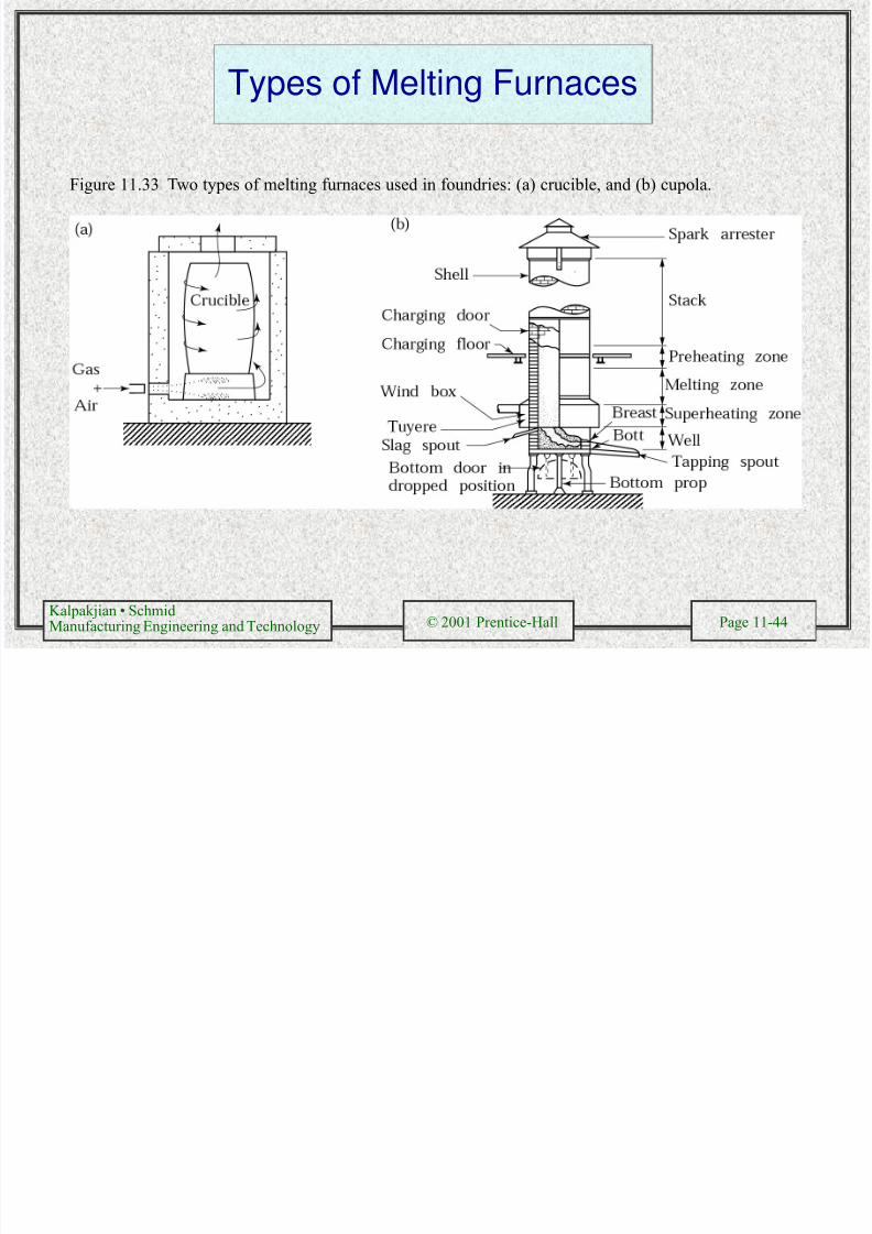
Types of Melting Furnaces
Figure 11.33 Two types of melting furnaces used in foundries: (a) crucible, and (b) cupola.
Casting Defects

8/19/2019 Metalurgi pengecoran
http://slidepdf.com/reader/full/metalurgi-pengecoran 45/49
Kalpakjian • Schmid
Manufacturing Engineering and Technology © 2001 Prentice-Hall Page 11-45
Casting Defects
Casting Defects

8/19/2019 Metalurgi pengecoran
http://slidepdf.com/reader/full/metalurgi-pengecoran 46/49
Kalpakjian • Schmid
Manufacturing Engineering and Technology © 2001 Prentice-Hall Page 11-46
Casting Defects
Porosity may be caused by shrinkage and/or gases
Thin sections solidify faster than thick sections; therefore
the molten metal cannot be supplied to thick regions thatare solidifying
Gases become less soluble in a metal as it cools andsolidifies, causing it to be expelled and sometimes form
or expand porosity
Casting Defects

8/19/2019 Metalurgi pengecoran
http://slidepdf.com/reader/full/metalurgi-pengecoran 47/49
Kalpakjian • Schmid
Manufacturing Engineering and Technology © 2001 Prentice-Hall Page 11-47
g
Casting Defects

8/19/2019 Metalurgi pengecoran
http://slidepdf.com/reader/full/metalurgi-pengecoran 48/49
Kalpakjian • Schmid
Manufacturing Engineering and Technology © 2001 Prentice-Hall Page 11-48
g
Chills
Pieces of material placed in the mold to speed upheat transfer in thicker areas of the part to
prevent shrinkage porosity
Internal chills are left within the cast part; externalchills are removed
Chills

8/19/2019 Metalurgi pengecoran
http://slidepdf.com/reader/full/metalurgi-pengecoran 49/49
Kalpakjian • Schmid
Manufacturing Engineering and Technology © 2001 Prentice-Hall Page 11-49