Embed Size (px)
Citation preview

1
Metasurface Reflector with Real-Time IndependentMagnitude and Phase Control
Ahmed Z. Ashoor, Member, IEEE and Shulabh Gupta, Senior Member, IEEE
Abstract—A novel metasurface unit cell architecture is pro-posed to enable independent control of the reflection magnitudeand phase at a desired operation frequency, while maintaininglinear polarization of the incoming fields. The proposed structureis based on a coupled-resonator configuration where a DipoleRing Resonator (DRR) is loaded with a tunable lumped resistiveelement (e.g. PIN diode) and Split Ring Resonator (SRR) loadedwith a lumped tunable capacitor (e.g. varactor diode), areinterleaved. The surface is next operated around one of thecoupled resonant frequency, where an independent tuning of thelumped capacitance and resistance elements enable a wide cov-erage of reflection amplitude-phase, which is significantly largerthan what would have been achievable using a single resonatorconfiguration. An insightful equivalent circuit model is furtherdeveloped for investigating the amplitude-phase characteristicsof a uniform surface as a function of variable resistance andcapacitance, which is next confirmed using full-wave simulations.Finally, using a variety of full-wave examples, the usefulnessof simultaneous and independent amplitude-phase control isdemonstrated, including cases of variable pattern gain with beamtilting and multi-beam pattern realization, which otherwise wouldnot be possible using either amplitude or phase control only.
Index Terms—Metasurfaces, Tunable Metasurface, EquivalentCircuit, Reflection Magnitude, Reflection Phase, Smart Reflector,Beam-steering, Multi-beam.
I. INTRODUCTION
Electromagnetic (EM) metasurfaces are 2D array sub-wavelength resonators that have recently emerged as a pow-erful platform for a variety of wave transformations includingamplitude and phase control in reflection and transmission, inaddition to the polarization manipulation [1]–[7]. A wide rangeof applications have been reported to control the reflected EMwave magnitude and phase such as anomalous reflections [8],EM wave absorbers [9], high impedance surfaces and artifi-cial magnetic conductors [10], and beam-forming and beamscanning antennas [11]–[13], to name a few. A recent trendin metasurface based electromagnetic wave control is to addgeneral space-time modulation of their constitutive parametersfor exotic applications such as artificial non-reciprocity andharmonic generation [7], [14]–[16].
For complete control over the scattered fields at a desiredoperating frequency f0, metasurfaces unit cells based on sub-wavelength resonators must be capable of providing a fullrange of amplitude and phase in the desired mode of operation- transmission or reflection, for each orthogonal polarization.For instance, if a reflection mode is desired, the unit cell mustindependently provide |Γ(f0)| ∈ [0, 1] (perfect absorption toperfect reflection) and ∠Γ(f0) ∈ [0, 2π], i.e. any combinationof |Γ|,∠Γ. A 2D array of such unit cell elements canthus provide an arbitrary field profile to be generated using
a spatially varying complex reflectance. Moreover, if bothphase and amplitude of each unit cell can individually bereal-time reconfigured on a pixel-by-pixel basis, the resultingmetasurface structure may represent an ideal platform forrealizing a software controlled smart reflector.
While several works have been done to achieve independentcontrol on phase and magnitudes [17]–[20], the majority ofthem have been restricted to passive metasurfaces only. Thesetechniques typically employ polarization rotation where theunit cell is physically rotated to introduce amplitude modula-tion of the desired polarization component, while the varyingunit cell dimensions are designed for phase control. Thisintroduces spurious cross-polarized components, which mayrequire separate processing to avoid undesired interferencewith the environment. Moreover, in various practical scenarios,a real-time control on the wave transformation through meta-surfaces is highly desirable, such as in application of thesesurfaces in wireless applications [21], where the channel char-acteristics are typically time-varying due to moving objectsand people, for instance. In these applications, the metasurfaceacts as a smart reflector for instance, which can adaptivelyguide and manipulate the EM waves as the environmentdynamically changes. Consequently, the metasurface must bereal-time reconfigurable.
Lot of work has been done in devising active metasurfaces(i.e.; programmable and tunable metasurfaces), whose reflec-tion/transmission fields can be controlled in real-time [22]–[29], further enabling software defined control capabilitiesaugmented using Machine Learning (ML) and Artificial In-telligence (AI) techniques [30]. The reconfiguration of thesurfaces is based on tunable components and materials whichare integrated on a unit cell level. Such techniques are typ-ically based on phase change materials such as graphene,temperature tuning, mechanical tuning or active microwaveelements tuning such as PIN (P-type, intrinsic, and N-typematerial) diodes and varactors [9]–[12], [31]. All these workshave focussed on tuning either the magnitude or phase therebynot utilizing the full capabilities of the metasurface, and thuslimited to a small subset of possible wave transformationcapabilities. It is clear that a real-time and independent controlof magnitude and phase of the scattered fields is an importantrequirement and a desirable feature in electromagnetic meta-surface design to fully exploit the wave control functionalitiesof general electromagnetic metasurfaces.
In this work, we propose a metasurface unit cell architecturewhich is capable of providing independent control of thefield magnitude and phase at the radio frequencies (RF),in reflection and in real-time without generating any cross-
arX
iv:2
009.
1336
9v1
[ph
ysic
s.ap
p-ph
] 2
8 Se
p 20
20

2
polarized scattered fields. The proposed metasurface is basedon a coupled-resonator configuration where each resonatoris separately tuned using a varactor and a PIN diode forphase and amplitude control, respectively. The initial idea wasproposed in [32] and a similar idea was presented in [33]for the optical frequencies in the Terahertz range based ontunable graphene material. Here, a more detailed full-wavedemonstration of its phase-amplitude coverage is presentedand compared to that of a single resonator. An equivalentcircuit model is next presented which is built using single res-onators providing further insights into the mechanism for thereflection control. Using several examples, the superiority ofthe combined amplitude-phase control in achieving a variety ofphase transformations over phase-only control is demonstratedusing full-wave simulation.
The paper is organized as follows. Sec. II motivates therequirements for both amplitude and phase control in achievinggeneral wave transformations and presents the proposed meta-surface. Sec. III shows a step-by-step development of an equiv-alent circuit model starting from two isolated resonators to acombined coupled-resonator unit cell. Sec. IV next presents avariety of full-wave examples to demonstrate the utilization ofspatially dependent amplitude and phase profiles for far-fieldbeam-forming applications. Sec. V presents a short discussionon the impact of the unit cell size on the requirements of thelumped capacitance ranges while providing large amplitude-phase coverages at a fixed operating frequency. Finally, con-clusions are provided in Sec. VI.
II. PROPOSED REFLECTION METASURFACE
Consider a reflection metasurface which is excited withan incident wave ψ0(r, ω), as illustrated in Fig. 1. Themetasurface is composed of an array of identical unit cells,where each unit cell is individually controlled with a tunablecapacitor and a resistor with separate external voltage controls(Vc, Vr). The tunable lumped elements integrated into theunit cell controls the spatially varying complex reflectance,Γ(x) = |Γ(x)|ej∠Γ(x), of the metasurface across the surface.By varying the voltage controls, we wish to reconfigure thereflected scattered fields, and in doing so, wish to devise a unitcell that is capable of providing a full range of reflection’samplitude |Γ(f0)| ∈ [0, 1] and phase ∠Γ(f0) ∈ [0, 2π]independently at a desired frequency of operation.
A. Need for Independent Magnitude/Phase Control
To illustrate the requirement and importance of controllingreflection magnitude and phase, consider that the metasurfaceis excited with a normally incident uniform plane-wave, forsimplicity. The reflected scattered fields in the far-field of thesurface due to spatially varying complex reflectance of thesurface, can be constructed using the standard array factorof antenna theory (linear polarization with no rotation isassumed). More specifically, considering the metasurface asan N−element linear array of unit cell size d, the overall
METASURFACEREFLECTOR
R(x) = |R(x)|ej∠R(x)
INCIDENT WAVEψ0(r, ω)
REFLECTED WAVEψref.(r, Vc1, Vr1)
REFLECTED WAVEψref.(r, Vc2, Vr2)
x
Unit Cell
V ncV nr
θ0
Fig. 1. Illustration of a reconfigurable metasurface reflector which transformsin incoming incident fields into desired scattered fields via active unit cellsconsisting of varactor diodes and PIN diodes for an independent phase andamplitude control, respectively.
reflection pattern of the surface (considering the surface as adistribution of point sources) may simply be modeled as
AF =
N∑n=1
anej(n−1)(kd cos θ+β) (1)
where an’s are the complex excitation coefficients for eachelement, β is the progression phase between the array’selements (which is zero for normally incident plane-wave,assumed here), k is the wavenumber, θ is the angle betweenthe axis of the array along the x−axis and the radial vectorfrom the origin to the observation point.
Let us take an example of a beam-steered metasurface whichreflects the incident beam at an angle of θ0. As well-knownfrom both antenna theory and metasurface analysis, a linearphase gradient across the metasurface will provide such abeam-tilt in the far-field. Fig. 2(a) shows an example, where
1 10 20 30 40 5000.20.40.60.8
1
1 10 20 30 40 50-180-90
090
180
-90 -45 0 45 90-40-30-20-10
0
|an|
∠an
(deg
)
Element number, n
AF
(dB
)
ASYMMETRIC SINGLE BEAM
UniformNon-uniform
(a)
1 10 20 30 40 5000.20.40.60.8
1
1 10 20 30 40 50-180-90
090
180
-90 -45 0 45 90-40-30-20-10
0
|an|
∠an
(deg
)
Element number, n
AF
(dB
)
UNEQUAL MAGNITUDE DUAL BEAM
(b)
Fig. 2. Illustrations on the importance of controlling the array’s elementsmagnitudes showing the Array Factors (AFs) of a uniform spaced linear arraywith uniform and non-uniform amplitude distributions with a specific phaseprogression. (a) The non-uniform and uniform AFs for a single tilted beamat an angle of 45 and (b) A multi-beam array tilted at angles of +/-45 witha different reflection gain for each beam.

3
the beam is reflected off θ0 = −45° using a metasurface offinite size, where a linear phase tilt and a uniform magnitudeprofile is imposed across the surface. As expected from auniform magnitude surface, the main radiation beam is ac-companied by side-lobes with peak-values at −13 dB, typicalof uniform apertures. If now instead, a spatially varying non-uniform magnitude profile is also imposed in addition to thephase, the side-lobes in the reflection field can be engineeredand greatly reduced1, as shown in Fig. 2(a) maintained at−30 dB, for instance. Another case that exemplifies theimportance of a simultaneous magnitude and phase controlis that of designing two asymmetrically located beams. Thisexample is shown in Fig. 2(b), where the incident wave is splitinto two beams, with unequal magnitudes. It is clear, that sucha reflection pattern cannot be achieved using either phase ormagnitude control only.
Split-RingOnly
Dipole-RingOnly
CoupledResonator
=
+
a
b
c
d
e
f
g
l
s
Λy
z x
Split-Ring Resonator(SRR) with
Tunable Capacitor
Dipole-Ring Resonator(DRR) with
Tunable Resistor
(a)
5 10 15 20 250
0.20.40.60.8
1
5 10 15 20 25-200-100
0100200
Frequency (GHz)
Mag
nitu
de,|
Γ|
Frequency (GHz)
Phas
e,∠
Γ(d
eg)
Coupled Resonator SRR DRR
(b)
8 10 12 14 16 180
0.20.40.60.8
1
8 10 12 14 16 18-200-100
0100200
Frequency (GHz)
Mag
nitu
de,|
Γ|
Frequency (GHz)
Phas
e,∠
Γ(d
eg)
C = 0.25 pF C = 0.1 pF C = 0.025 pF
DecreasingCapacitance
IncreasingResistance
(c)
Fig. 3. Proposed metasurface unit cell architecture based on coupled SplitRing Resonator (SRR) and Dipole Ring Resonator (DRR), loaded with tunablecapacitor and resistor respectively. (b) FEM-Simulated magnitude and phaseof three configuration (R = 25 Ω and C = 0.1 pF). (c) Simulated magnitudeand phase of the coupled-resonator unit cell with three different resistances(R = 5, 25, 50 Ω) and three different capacitances (C = 0.025, 0.1, 0.25 pF).All simulations performed in FEM-HFSS, and the various dimensions areprovided in Tab. I.
1Several amplitude tapering schemes exist in standard antenna theorytextbooks on array synthesis. Chebyshev arrays is used here as an example.
B. Proposed Coupled-Resonator Structure
A conventional reflection unit cell providing real-time phasecontrol consists of a lumped tuning element, typically avaractor diode for instance at Radio Frequencies (RF), whichis integrated inside a sub-wavelength resonator. Two simplegeometries that are commonly used are Split Ring Resonator(SRR) and Dipole Ring Resonator (DRR), as shown in Fig-ure 3(a). As their resonance frequency is tuned via lumpedcapacitance, the reflection phase at a desired fixed frequencyis changed along with an uncontrolled magnitude variationdue to dissipation losses of the materials. For a controlledmagnitude variation, a second dissipative element must beadded that controls the resonator losses, which should ideallyoperate independently of the capacitance value.
Figure 3(a) further shows the proposed unit cell formedas a combination of an SRR and DRR, incorporating thesetwo lumped elements for achieving independent amplitude andphase control. The architecture specifically consists of an SRRloaded with a varactor acting as a tunable capacitor whichdominantly controls its resonant frequency. A second DRRis inserted inside the SRR loaded with a PIN diode, actingas a tunable resistor which controls the reflection magnitudeof the cell2. Since the two resonators are strongly coupled,the unit cell is operated at one of its coupled resonances, sothat its reflection magnitude and phase is controlled by thetwo lumped tuning elements together. In all cases, the unitcell period Λ λ0 to maintain sub-wavelength characteristicsfor good spatial discretization of magnitude and phase whenconfigured to form a non-uniform metasurface.
A typical unit cell response of the proposed unit cell isshown in Fig. 3(b), along with those of isolated SRR and DRRstructures, loaded with capacitance C and resistance R, respec-tively. Owing to the larger resonant length, the SRR features alower resonant frequency (dashed blue curve) compared to thatof DRR (dashed black curve) when working in isolation, andthus have different frequency of resonances. When they aresuperimposed, they are strongly coupled electromagnetically,and the resonant frequencies of the combined unit cell arestrongly perturbed, as seen in Fig. 3(b).
Now, we can choose to operate at one of these resonantfrequencies knowing that the resonant frequency f0 and theQ-factor depend on both the capacitance and resistance values.This is illustrated in Fig. 3(c) using one of the resonantpeaks of the coupled system. For a fixed capacitance valueC, when the resistance of the DRR is changed, the Q-factor(= f0/∆f ) changes with minimal effect on f0. Larger R isseen to correspond to lower reflection from the surface, whilemaintaining the resonance frequency and thus the reflectionphase. As the capacitance is decreased, the resonant frequencyf0 is increased as expected, while nearly maintaining itsreflection magnitude level. Thus C and R represent twoindependent controls on the reflection phase and magnitudewith minimal interdependence.
2While SRR and DRR are used here for convenience, the unit cell may beadapted with more sophisticated resonator geometries for greater wave controlsuch as manipulating polarization, for instance.

4
2.5 9.25 16 22.75 29.5
20
40
60
80
100 0
0.2
0.4
0.6
0.8
1
2.5 9.25 16 22.75 29.5
20
40
60
80
100 -180-120-600601201800 0
Capacitance ×10−2(pF)
Res
ista
nce
(Ω)
Capacitance ×10−2(pF)
Res
ista
nce
(Ω)
(Unit CellFEM-HFSS)
|Γ| (f = 12.5 GHz) ∠Γ (f = 12.5 GHz)
SIN
GL
ER
ESO
NA
TO
R(D
RR
)
(a)
2.5 9.25 16 22.75 29.5
20
40
60
80
100 0
0.2
0.4
0.6
0.8
1
2.5 9.25 16 22.75 29.5
20
40
60
80
100 -180-120-600601201800 0
Capacitance ×10−2(pF)
Res
ista
nce
(Ω)
Capacitance ×10−2(pF)
Res
ista
nce
(Ω)
|Γ| (f = 18.5 GHz) ∠Γ (f = 18.5 GHz)
CO
UP
LE
DR
ESO
NA
TO
R
(Unit CellFEM-HFSS)
(b)
Fig. 4. FEM-HFSS simulated amplitude-phase distribution at a fixed fre-quency as a function of lumped element values. (a) Proposed coupler resonatorunit cell. (b) Dipole Ring Resonator unit cell where the resistance andcapacitance are configured in series in its gap. All simulations performedin FEM-HFSS, and the various dimensions are provided in Tab. I.
-180
-120
-60
0
60
120
180
0 0.2 0.4 0.6 0.8 1Magnitude, |Γ|
phas
e,∠
Γ(d
eg)
SINGLE RESONATOR (DRR)
(a)
0 0.2 0.4 0.6 0.8 1-180
-120
-60
0
60
120
180
Magnitude, |Γ|
phas
e,∠
Γ(d
eg)
PROPOSED COUPLED RESONATOR
(b)
Fig. 5. Amplitude-phase coverage plots for the unit cells of Fig. 4 showingachievable values using the capacitance values ranging between 0.025 −0.295 pF and resistance values ranging between 1 − 100 Ω.(a) A singledipole-ring resonator of Fig. 4(b). (b) Proposed coupled-resonator of Fig. 4(a).
In practical cases, the operation frequency f0 is typicallyfixed and thus it is preferable to obtain the amplitude-phase map achievable through a given unit cell configuration.Fig. 4(a) shows a 2D map of the reflection magnitude andphase for varying R and C at a fixed f0. The reflection phaseshows only a slight variation as the resistance value is changedfor a fixed capacitance, while large variation is seen in themagnitude response. On the other hand, the reflection phase isgradually decreased as Capacitance increases, except near theregions where the surface is fully absorptive, i.e. |Γ| ≈ 0. If aspecific reflection amplitude-phase pair |Γ|,∠Γ is sought,the phase is first fixed to ∠Γ by choosing an appropriatecapacitance C0, followed by resistance R0 tuning to achievethe desired reflection magnitude of |Γ|.
At this point, one may wonder if a single SRR or DRRresonator with both R and C may also provide an independentamplitude and phase control? To investigate this, Fig. 5(b)
shows the 2D reflection amplitude and phase maps for a DRRunit cell where a series R − C is integrated on the gap. Inthis case, large phase tuning is observed at a higher frequencyfor the same lumped element ranges as that of Fig. 4(a) (i.e.18.5 GHz vs 12.5 GHz, around the isolated resonance ofthe DRR). No clear independent control is visible, althoughsome combinations of R − C may be found which canprovide desired |Γ|,∠Γ combinations. This amplitude-phasecoverage range, may more clearly be seen in Fig. 5, whereeach pixel represents amplitude-phase combinations which arepossible to achieve using a certain R,C combination. Whilea single resonator configuration shows a dense distributionwith a large magnitude variation, the phase range is restricted,in addition to a lack of a clear mapping between R,C and|Γ|,∠Γ. On the other hand, the combined proposed unit cellfeatures a well-defined distribution with significantly largercoverage across both phase and magnitude.
It should further be noted that even though some level ofamplitude-phase control is possible using a single resonator-based unit cell, it is not particularly suited for practicalimplementation. Both the varactor and the PIN diodes as prac-tical means of controlling capacitance and resistance requireseparate voltage control lines for reverse-biasing and forward-biasing, respectively, which is not convenient in a singleresonator configuration. On the other hand, for the proposedcoupled-resonator cells, since the two lumped elements arephysically disconnected and located on different resonators,they can be individually biased using standard biasing net-works with no practical difficulty. Therefore, the proposedcoupled-resonator architecture is clearly superior to a singleresonator-based one from both electrical as well as practicalimplementation point of view.
III. CIRCUIT MODELS ANALYSIS
A better insight into the proposed metasurface structure maybe gained using an equivalent circuit model representation.Since the proposed metasurface’s unit cell consists of twocoupled-resonators, namely DRR and SRR, a circuit model isdeveloped for each resonator individually with its respectivetuning element. Then the overall response of the metasurface’sunit cell is constructed by combining the developed equivalentcircuit models of the two resonators, DRR and SRR, consid-ering the electromagnetic coupling effects.
A. Single Resonator (Dipole/Split-Ring)
The two metasurface’s unit cell resonators, i.e., the DRRand SRR resonators, can be modeled using a circuit modelrepresentation approach [34]. The equivalent circuit modelsare based on equivalent transmission lines representation ofthe metasurface’s unit cell resonators. The DRR is modeledwith a two-shunt combination of series RLC when a normallyincident free space plane-wave with a characteristic impedanceof Z0 excites the DRR with an E-field being polarized alongthe y−axis as shown in Fig. 6(a). When the DRR’s excitinggap is loaded with an active element such as a PIN diode tocontrol the overall impedance of the DRR, a loaded resistanceR representing the overall impedance of the active element
5
is modeled in shunt across the DRR’s gap c1. The couplingbetween the adjacent cells is represented by c2.
The SRR equivalent circuit, on the other hand, is modeledsimilarly with a two-shunt combination of series RLC asshown in Fig. 6(b) with some modifications that account forthe off-balanced normally incident E-field along the y−axis.An off-balanced E-field is seen by the two SRR’s arms andbetween the adjacent cells when its gap c3 is loaded withan active element such as a varactor C while c1 and c2represent the coupling between the adjacent cells on eachSRR arms. Shunt capacitances of c4 and k(C) are modeled toaccount for cell asymmetry and account for the changes on theinter-element coupling capacitance due to the changes in theactive loaded capacitance C. Finally, the grounded dielectricsubstrate on both the DRR and SRR resonators is modeled asa shorted transmission line with a characteristic impedance ofZ with shunt capacitance cd and cs, respectively, accountingfor the small electromagnetic coupling between the resonatorsand their grounded dielectric substrates.
The equivalent circuit models of the two single resonatorswere simulated using the advanced design simulator (ADS)and compared with the full-wave finite element simulator(HFSS) for a wide range of frequency bandwidth. The full-wave response of the unit cells was curve fitted by numericallyfinding various lumped element values of the equivalent circuitmodel. Fig. 6(c) compares the full-wave simulation of thereflection’s magnitude and phase with the obtained responsesby the lumped element circuit models from 5−30 GHz forthe DRR when its gap or its equivalent in the circuit modelis loaded with a resistance of R = 50 Ω, and the SRR when
l1 l2
c1 c2
r1 r2
cd
cd
R
Γ(f0)
Z0
Z, θ
Z, θ
Zshort
DIPOLE RING RESONATOR SPLIT RING RESONATOR
(a)
l1 l2c1 c2
c3 c4
r1 r2
cs
cs
C kC
Γ(f0)
Z0
Z, θ
Z, θ
Zshort
(b)
5 10 15 20 25 300
0.20.40.60.8
1
5 10 15 20 25 30-200-100
0100200
5 10 15 20 25 300
0.20.40.60.8
1
5 10 15 20 25 30-300-150
0150300
Frequency (GHz)
Phas
e,∠
Γ(d
eg)
Frequency (GHz)
Phas
e,∠
Γ(d
eg)
Frequency (GHz)
Mag
nitu
de,|
Γ|
Frequency (GHz)
Mag
nitu
de,|
Γ|
EquivalentCircuit Model
Unit CellFEM-HFSS
(c)
Fig. 6. Developed equivalent circuit models of (a) the DRR and (b) theSRR with tunable resistance and capacitance, respectively. (c) Comparison ofFEM-HFSS simulation with that of circuit model for the DRR (left) and SRR(right). The various circuit’s parameters are summarized in Tab. I.
l1 l2
c1 c2
r1 r2
cd
cd
R
l3 l4c3 c4
c5 c6 kC
r3 r4
cs
cs
C
Γ(f0), Z0
Z, θ
Grounded Dielectric
Zshort
DRR with TunableResistor
SRR with TunableCapacitor
(a)
8 10 12 14 16 180
0.20.40.60.8
1
8 10 12 14 16 18-200-100
0100200
8 10 12 14 16 180
0.20.40.60.8
1
8 10 12 14 16 18-200-100
0100200
8 10 12 14 16 180
0.20.40.60.8
1
8 10 12 14 16 18-200-100
0100200
8 10 12 14 16 180
0.20.40.60.8
1
8 10 12 14 16 18-200-100
0100200
8 10 12 14 16 180
0.20.40.60.8
1
8 10 12 14 16 1880
130180230280
8 10 12 14 16 180
0.20.40.60.8
1
8 10 12 14 16 1880
130180230280
Frequency (GHz) Frequency (GHz)
Mag
nitu
de,|
Γ|
Phas
e,∠
Γ(d
eg)
R=
100
ΩC
=0.2
5pF
Mag
nitu
de,|
Γ|
Phas
e,∠
Γ(d
eg)
R=
100
ΩC
=0.0
25
pF
Mag
nitu
de,|
Γ|
Phas
e,∠
Γ(d
eg)
R=
50
ΩC
=0.2
5pF
Mag
nitu
de,|
Γ|
Phas
e,∠
Γ(d
eg)
R=
50
ΩC
=0.0
25
pF
Mag
nitu
de,|
Γ|
Phas
e,∠
Γ(d
eg)
R=
5Ω
C=
0.2
5pF
Mag
nitu
de,|
Γ|
Phas
e,∠
Γ(d
eg)
R=
5Ω
C=
0.0
25
pF
EquivalentCircuit Model
Unit CellFEM-HFSS
(b)
Fig. 7. Proposed equivalent circuit model of the coupled-resonator basedmetasurface unit cell. (a) Equivalent circuit model. (b) Comparison of FEM-HFSS simulation with circuit model results for several R and C values. Thevarious circuit’s parameters are summarized in Tab. I.
its gap or its equivalent in the circuit model is loaded witha capacitance of C = 0.18 pF. The full-wave simulationresults of the two resonators show good agreement with theirequivalent circuit models with the loaded elements R and Cfor large ranges of value (not shown here). This supports the

6
2.5 9.25 16 22.75 29.5
20
40
60
80
100 0
0.2
0.4
0.6
0.8
1
2.5 9.25 16 22.75 29.5
20
40
60
80
100 -180-120-60060120180
2.5 9.25 16 22.75 29.5
20
40
60
80
100 0
0.2
0.4
0.6
0.8
1
2.5 9.25 16 22.75 29.5
20
40
60
80
100 -180-120-60060120180
2.5 9.25 16 22.75 29.5
20
40
60
80
100 0
0.2
0.4
0.6
0.8
1
2.5 9.25 16 22.75 29.5
20
40
60
80
100 -180-120-60060120180
0
0
0
0
0
0
Capacitance ×10−2(pF)
Res
ista
nce
(Ω)
Capacitance ×10−2(pF)
Res
ista
nce
(Ω)
Capacitance ×10−2(pF)
Res
ista
nce
(Ω)
Capacitance ×10−2(pF)
Res
ista
nce
(Ω)
Capacitance ×10−2(pF)
Res
ista
nce
(Ω)
Capacitance ×10−2(pF)
Res
ista
nce
(Ω)
REFLECTION MAGNITUDE, |Γ| REFLECTION PHASE, ∠Γf0
=13
GH
Zf0
=12
GH
Zf0
=11
GH
Z
EQUIVALENT
CIRCUIT MODEL
(a)
2.5 9.25 16 22.75 29.5
20
40
60
80
100 0
0.2
0.4
0.6
0.8
1
2.5 9.25 16 22.75 29.5
20
40
60
80
100 -180-120-60060120180
2.5 9.25 16 22.75 29.5
20
40
60
80
100 0
0.2
0.4
0.6
0.8
1
2.5 9.25 16 22.75 29.5
20
40
60
80
100 -180-120-60060120180
2.5 9.25 16 22.75 29.5
20
40
60
80
100 0
0.2
0.4
0.6
0.8
1
2.5 9.25 16 22.75 29.5
20
40
60
80
100 -180-120-60060120180
0
0
0
0
0
0
Capacitance ×10−2(pF)
Res
ista
nce
(Ω)
Capacitance ×10−2(pF)
Res
ista
nce
(Ω)
Capacitance ×10−2(pF)
Res
ista
nce
(Ω)
Capacitance ×10−2(pF)
Res
ista
nce
(Ω)
Capacitance ×10−2(pF)
Res
ista
nce
(Ω)
Capacitance ×10−2(pF)
Res
ista
nce
(Ω)
REFLECTION MAGNITUDE, |Γ| REFLECTION PHASE, ∠Γ
f0
=13
GH
Zf0
=12
GH
Zf0
=11
GH
Z
FEM-HFSS
(b)
Fig. 8. Comparison of the equivalent circuit model (a) of Fig. 7(a) with FEM-HFSS (b), shown using the R− C dependent reflection amplitude-phase forthe proposed coupled-resonator metasurface cell for capacitance values rangedbetween 0.025− 0.295 pF and resistance values ranged between 1− 100 Ωat different operating frequencies
suitability of the proposed circuit model to correctly representthe two physical models of DRR and SRR.
B. coupled-resonator (Dipole-Split-Ring)
The proposed metasurface unit cell based on coupled-resonators is next modeled using the above circuit modelsfor the isolated resonators. The DRR and SRR circuit modelsabove were superimposed to model the equivalent circuitmodel of the proposed metasurface unit cell. Fig. 7(a) shows
the superimposed configuration for the metasurface equivalentcircuit model (its details lumped elements parameters aresummarized in Tab. I. Once the two-unit cells are superim-posed, they are electromagnetically coupled, which as a resultperturbs its various circuit element values. Fig. 7(b) comparesthe reflection’s magnitude and phase for the metasurface unitcell with the obtained responses by its equivalent circuit modelusing different values of R and C for the controlling loadedresistance and capacitance. The metasurface’s circuit modelmagnitude and phase responses are in good agreement withthe obtained full-wave simulation results.
One major motivation of building an equivalent cir-cuit model for the proposed metasurface (i.e; the coupled-resonator) is to build a faster approach than the full-wavesimulation to examine the coverage range of magnitude andphase capability of the metasurface. Fig. 8(a) shows two-dimensional contour views of the reflection’s magnitude andphase coverage for the proposed metasurface unit cell obtainedusing its equivalent circuit model at three different frequen-cies. The used capacitance values C are ranged between0.025 − 0.295 pF and the resistance values R are rangedbetween 1 − 100 Ω (typical among commercially availableoff-the-shelf varactor and PIN diodes). Similarly, the full-wavesimulator HFSS is used to compare those contour coveragesobtained by the equivalent circuit model at different operatingfrequencies as shown in Fig. 8(b). The contour views ofthe reflection magnitude and phase coverages show similartrends and frequency variations for results obtained using theequivalent circuit model and full-wave simulator. The resultsshown in Fig. 8 thus not only substantiate the equivalentcircuit model but also shows the capability of the proposedmetasurface cells with the two combined resonators to havesimilar reflection magnitude and phase coverage at differentoperating frequencies.
IV. FULL-WAVE DEMONSTRATION
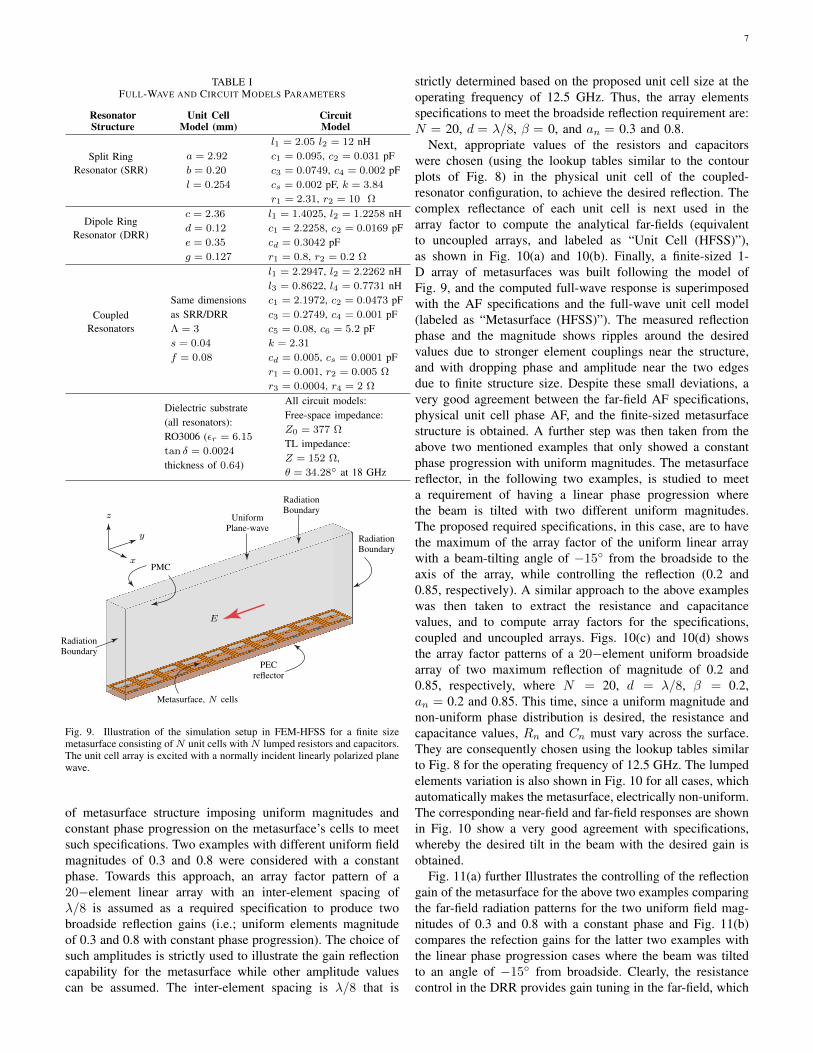
This section will demonstrate different numerical examplesexamining the reflection capability of the proposed meta-surface to meet specific beam-forming, tilting, and splittingspecifications, using simultaneous amplitude and phase controlobtained through the integrated active resistors and capacitors.The HFSS simulation setup to model a coupled array ofidentical unit cells forming the metasurface is illustrated inFig 9 (for reasonable computational time). The amplitudeand variation are obtained by varying the lumped elements(and not the geometry) across the surface. The finite sizemetasurface is assumed to be excited by a normally incidentplane-wave along the z−axis with an E−field polarized alongthe y−axis, and where the metasurface structure is assumed tobe uniform along the x−axis using PMC and PEC boundaries,respectively. Radiation boundaries enclose the structure topand sides. A fixed operation frequency of 12.5 GHz is assumedin all illustration examples. It’s well-known that havinglinear array elements of uniform magnitudes with constantphase progression will produce a maximum reflection beamdirected broadside to the axis of the excited linear arrayelements. Thus, we start examining the reflection response
7
TABLE IFULL-WAVE AND CIRCUIT MODELS PARAMETERS
ResonatorStructure
Unit CellModel (mm)
CircuitModel
Split RingResonator (SRR)
a = 2.92
b = 0.20
l = 0.254
l1 = 2.05 l2 = 12 nHc1 = 0.095, c2 = 0.031 pFc3 = 0.0749, c4 = 0.002 pFcs = 0.002 pF, k = 3.84
r1 = 2.31, r2 = 10 Ω
Dipole RingResonator (DRR)
c = 2.36
d = 0.12
e = 0.35
g = 0.127
l1 = 1.4025, l2 = 1.2258 nHc1 = 2.2258, c2 = 0.0169 pFcd = 0.3042 pFr1 = 0.8, r2 = 0.2 Ω
CoupledResonators
Same dimensionsas SRR/DRRΛ = 3
s = 0.04
f = 0.08
l1 = 2.2947, l2 = 2.2262 nHl3 = 0.8622, l4 = 0.7731 nHc1 = 2.1972, c2 = 0.0473 pFc3 = 0.2749, c4 = 0.001 pFc5 = 0.08, c6 = 5.2 pFk = 2.31
cd = 0.005, cs = 0.0001 pFr1 = 0.001, r2 = 0.005 Ω
r3 = 0.0004, r4 = 2 Ω
Dielectric substrate(all resonators):RO3006 (εr = 6.15
tan δ = 0.0024
thickness of 0.64)
All circuit models:Free-space impedance:Z0 = 377 Ω
TL impedance:Z = 152 Ω,θ = 34.28 at 18 GHz
RadiationBoundary
RadiationBoundary
RadiationBoundary
PMC
PECreflector
Metasurface, N cells
UniformPlane-wave
E
y
z
x
Fig. 9. Illustration of the simulation setup in FEM-HFSS for a finite sizemetasurface consisting of N unit cells with N lumped resistors and capacitors.The unit cell array is excited with a normally incident linearly polarized planewave.
of metasurface structure imposing uniform magnitudes andconstant phase progression on the metasurface’s cells to meetsuch specifications. Two examples with different uniform fieldmagnitudes of 0.3 and 0.8 were considered with a constantphase. Towards this approach, an array factor pattern of a20−element linear array with an inter-element spacing ofλ/8 is assumed as a required specification to produce twobroadside reflection gains (i.e.; uniform elements magnitudeof 0.3 and 0.8 with constant phase progression). The choice ofsuch amplitudes is strictly used to illustrate the gain reflectioncapability for the metasurface while other amplitude valuescan be assumed. The inter-element spacing is λ/8 that is
strictly determined based on the proposed unit cell size at theoperating frequency of 12.5 GHz. Thus, the array elementsspecifications to meet the broadside reflection requirement are:N = 20, d = λ/8, β = 0, and an = 0.3 and 0.8.
Next, appropriate values of the resistors and capacitorswere chosen (using the lookup tables similar to the contourplots of Fig. 8) in the physical unit cell of the coupled-resonator configuration, to achieve the desired reflection. Thecomplex reflectance of each unit cell is next used in thearray factor to compute the analytical far-fields (equivalentto uncoupled arrays, and labeled as “Unit Cell (HFSS)”),as shown in Fig. 10(a) and 10(b). Finally, a finite-sized 1-D array of metasurfaces was built following the model ofFig. 9, and the computed full-wave response is superimposedwith the AF specifications and the full-wave unit cell model(labeled as “Metasurface (HFSS)”). The measured reflectionphase and the magnitude shows ripples around the desiredvalues due to stronger element couplings near the structure,and with dropping phase and amplitude near the two edgesdue to finite structure size. Despite these small deviations, avery good agreement between the far-field AF specifications,physical unit cell phase AF, and the finite-sized metasurfacestructure is obtained. A further step was then taken from theabove two mentioned examples that only showed a constantphase progression with uniform magnitudes. The metasurfacereflector, in the following two examples, is studied to meeta requirement of having a linear phase progression wherethe beam is tilted with two different uniform magnitudes.The proposed required specifications, in this case, are to havethe maximum of the array factor of the uniform linear arraywith a beam-tilting angle of −15 from the broadside to theaxis of the array, while controlling the reflection (0.2 and0.85, respectively). A similar approach to the above exampleswas then taken to extract the resistance and capacitancevalues, and to compute array factors for the specifications,coupled and uncoupled arrays. Figs. 10(c) and 10(d) showsthe array factor patterns of a 20−element uniform broadsidearray of two maximum reflection of magnitude of 0.2 and0.85, respectively, where N = 20, d = λ/8, β = 0.2,an = 0.2 and 0.85. This time, since a uniform magnitude andnon-uniform phase distribution is desired, the resistance andcapacitance values, Rn and Cn must vary across the surface.They are consequently chosen using the lookup tables similarto Fig. 8 for the operating frequency of 12.5 GHz. The lumpedelements variation is also shown in Fig. 10 for all cases, whichautomatically makes the metasurface, electrically non-uniform.The corresponding near-field and far-field responses are shownin Fig. 10 show a very good agreement with specifications,whereby the desired tilt in the beam with the desired gain isobtained.
Fig. 11(a) further Illustrates the controlling of the reflectiongain of the metasurface for the above two examples comparingthe far-field radiation patterns for the two uniform field mag-nitudes of 0.3 and 0.8 with a constant phase and Fig. 11(b)compares the refection gains for the latter two examples withthe linear phase progression cases where the beam was tiltedto an angle of −15 from broadside. Clearly, the resistancecontrol in the DRR provides gain tuning in the far-field, which

8
1
5
10
15
200.04 0.08 0.12
1
5
10
15
20
00.4 1
5
10
15
20
-180-90090180
-60
-30
0
30
6090
-25-20-15-10-50
0
-90
25 75 100 0.8Resistance (Ω)
Capacitance (pF)
Cel
lnu
mbe
r,n
Magnitude Phase (deg)
AF (theoretical) Unit cell (HFSS) Metasurface (HFSS)
LUMPED ELEMENTC(n), R(n)
NEAR-FIELD|E(y, z0)|
NEAR-FIELD∠E(y, z0)
FAR-FIELD GAINGθ(θ, φ = 90)
θP
EA
K=
0
,|Γ
1|
(a)
5
10
15
200.04 0.08 0.12
1
5
10
15
20
00.20.40.60.811
5
10
15
20
-180-90090180
-90-60
-30
0
30
6090
-25-20-15-10-50
10 25 75 100
Resistance (Ω)
Capacitance (pF)
Cel
lnu
mbe
r,n
Magnitude Phase (deg)
AF (theoretical) Unit cell (HFSS) Metasurface (HFSS)
LUMPED ELEMENTC(n), R(n)
NEAR-FIELD|E(y, z0)|
NEAR-FIELD∠E(y, z0)
FAR-FIELD GAINGθ(θ, φ = 90)
θP
EA
K=
0,|Γ
2 |
(b)
1
5
10
15
200.02 0.06 0.1
1
5
10
15
20
00.20.40.60.811
5
10
15
20
-180-90090180
-90-60
-30
0
30
6090
-25-20-15-10-50
0 25 75 100Resistance (Ω)
Capacitance (pF)
Cel
lnu
mbe
r,n
Magnitude Phase (deg)
AF (theoretical) Unit cell (HFSS) Metasurface (HFSS)
θP
EA
K=−
15
,|Γ
1|
(c)
5
10
15
200.02 0.06 0.1
1
5
10
15
20
00.20.40.60.811
5
10
15
20
-180-90090180
-90-60
-30
0
30
6090
-25-20-15-10-50
10 25 75 100
Resistance (Ω)
Capacitance (pF)
Cel
lnu
mbe
r,n
Magnitude Phase (deg)
AF (theoretical) Unit cell (HFSS) Metasurface (HFSS)
θP
EA
K=−
15,|Γ
2 |
(d)
Fig. 10. Metasurface for beam-deflection with variable gain control. (a)-(b) Specified peak reflection of 0.3 and 0.8, respectively, with no beam deflection.(c)-(d) Specified peak reflection of 0.2 and 0.85, respectively, with beam deflection to 15. Normally incident plane-wave is assumed in all cases andmetasurface consists of 20 cells. Each plot shows the resistance, R and capacitance C variation across the surfaces, along with spatially varying magnitudeand phase. Array Factor (AF) shows the ideal element distributions, “unit cell” corresponds to a physical unit cell simulated in HFSS with Floquet boundaryconditions, and “metasurface” corresponds to a non-uniform full-wave structure with varying R and C. The reflected scattered fields are shown in the far-fieldusing radiation pattern plots.
-90
-60
-300
30
60
90-25 -20 -15 -10 -5 0
∣∣∣∣S11
∣∣∣∣ = 0.3
∣∣∣∣S11
∣∣∣∣ = 0.8
NO TILT, Variable Gain
(a)
-90
-60
-300
30
60
90-25 -20 -15 -10 -5 0
∣∣∣∣S11
∣∣∣∣ = 0.2
∣∣∣∣S11
∣∣∣∣ = 0.85
BEAM TILT, Variable Gain
(b)
Fig. 11. Normalized far-field radiation patterns obtained by the FEM-HFSS for a finite metasurface of 20 coupled cells for: (a) a constant phaseprogression with two uniform field magnitudes of 0.3 and 0.8, and (b) a linearphase progressions with different field magnitudes of 0.2 and 0.85.
could range from a near-perfect reflection (except accountingfor dissipation losses) to perfect absorption.
Next, we imposed more sophisticated scenarios where weassumed a specific side lobes level (grating lobes) that isrequired for broadside reflection as well as for achieving beamdeflection. Thus, the following two examples will require themetasurface to maintain a lower sider level and to exhibit non-uniform magnitudes with constant and linear phase progres-sion, respectively. The first example in the category is to havea reflection in a broadside direction. This example assumesthat the specifications are having maximum side lobes at least25 dB below the main lobe directed along broadside whilethe main beam width is as small as possible. To meet thesespecifications, all elements will have the same phase excitation(i.e.; constant progression phase) and non-uniform amplitudeexcitation of the array elements. For the element amplitude,a Chebyshev array of N = 48 elements and inter-elementspacing of d = λ/8 is chosen to meet these specifications, asChebyshev profiles are well-known to provide equi-ripple side-
lobes in antenna theory. The Chebyshev AF of N−elementarray requires a Chebyshev polynomial Tm(z) of m = N − 1order that is defined as follow:
Tm(z) =
(−1)m coshm. cosh−1 |z|, z 6 −1
cosm cos−1(z), − 1 6 z 6 1
coshm cosh−1(z), z ≥ 1
(2)
and the ratio R0 of major to minor lob intensity is themaximum of TN−1 that is fixed at an argument z0 (|z0| > 1)where Tmax
m (z0) = R0. The specified AF using the Chebyshevpolynomial is then equated to determining the coefficients foreach power of z that satisfies an R0 of 25 dB for a broadsidebeam with β = 0. Complex weights are obtained for thearray element excitations. Figs. 12(a) shows an example of thisChebyshev linear array with a broadside beam and comparesthe required AF specifications with both the unit cell and themetasurface. A near-perfect magnitude and phase response areobserved, and again, Despite a constant phase, both R and Care varied across the surface. Consequently, an excellent matchbetween the realized pattern and the specifications is observedin the far-field.
Then, similar to the above specifications for having maxi-mum side lobes with at least a 25 dB below the main lobe ofan array factor, we also added another requirement - that is totilt the reflected beam with an angle of 7 from the broadside,for instance. Thus, we investigated non-standard magnitudedistributions, mainly to see how well the surface will followsuch distributions, for the array elements’ magnitude that is ina form of an approximate binomial distribution that is defined

9
1
10
20
30
40
500.04 0.08 0.12
1
10
20
30
40
50
00.20.40.60.811
10
20
30
40
50
-180-90090180
-90-60
-30
0
30
6090
-25-20-15-10-50
0 25 50 75 100Resistance (Ω)
Capacitance (pF)C
ell
num
ber,n
Magnitude Phase (deg)
AF (theoretical) Unit cell (HFSS) Metasurface (HFSS)
LUMPED ELEMENTC(n), R(n)
NEAR-FIELD|E(y, z0)|
NEAR-FIELD∠E(y, z0)
FAR-FIELD GAINGθ(θ, φ = 90)
BR
OA
DSI
DE
RE
FLE
CT
ION
(a)
1
10
20
30
40
500.04 0.08 0.12
1
10
20
30
40
50
00.20.40.60.811
10
20
30
40
50
-180-90090180
-90-60
-30
0
30
6090
-25-20-15-10-50
0 25 50 75 100Resistance (Ω)
Capacitance (pF)
Cel
lnu
mbe
r,n
Magnitude Phase (deg)
AF (theoretical) Unit cell (HFSS) Metasurface (HFSS)
OFF
-BR
OA
DSI
DE
RE
FLE
CT
ION
(b)
Fig. 12. Metasurface reflector for beam-deflection with controlled side-lobes(minimum 25 dB below peak gain). (a) Chebyshev magnitude distribution anda constant phase progression (no beam deflection) (b) Approximated binomialmagnitude distribution and a linear phase progression (beam deflection).Normally incident plane-wave is assumed, and the metasurface is 48 cellslong.
as follow:
an =
1− 0.9n, for n = 1 to N/2
1− 0.9n−(2m+1),for n = (N/2 + 1) to N ;m = 0 to (N/2− 1)
(3)A linear array with 48−element with an inter-element spacingof d = λ/8 and non-uniform amplitudes is again used (i.e.;the approximate binomial expressed on Eq. 3). An arrayfactor pattern satisfying those specifications is obtained fora 48−element array (N = 48, d = λ/8, β = 0.1 rad/m).Fig. 12(b) shows and compares the required specifications’AF with both the unit cell (i.e.; capacitances and resistancesobtained from the uncoupled metasurface unit cell) and thefinite linear metasurface array. Again, a clear beam tilt withlow side-lobes is obtained as a result of simultaneous variationof phase and magnitude across the surface. Lastly, we examinethe metasurface reflector by specifying two scenarios for hav-ing obtaining multi-beams in reflection. The first specificationrequirement is to have a two-beam reflection with identicalgains where one beam is tilted at 27 from the broadside andthe other one is at -27 with a major-to-minor lobe ratio ofR0 = 60 dB. The Chebyshev array is used here to meet suchspecifications. The two beams are equated with linear phaseprogression of (β = 0.35 rad/m) and (β = −0.35 rad/m)to satisfies the required tilting angles of ±27, respectively.Figs. 13(a) shows the resulting two identically directive beamswith minimum side lobes with an identical gain comparedto the specifications, showing an excellent agreement. Thesecond specification requirement is a more general one, withtwo beams having different gains where the higher gainbeam is on the broadside and the other beam is at a 30
1
10
20
30
40
500.04 0.08 0.12
1
10
20
30
40
50
00.20.40.60.811
10
20
30
40
50
-180-90090180
-90-60
-30
0
30
6090
-25-20-15-10-50
0 25 50 75 100Resistance (Ω)
Capacitance (pF)
Cel
lnu
mbe
r,n
Magnitude Phase (deg)
AF (theoretical) Unit cell (HFSS) Metasurface (HFSS)
LUMPED ELEMENTC(n), R(n)
NEAR-FIELD|E(y, z0)|
NEAR-FIELD∠E(y, z0)
FAR-FIELD GAINGθ(θ, φ = 90)
SYM
ME
TR
ICR
EFL
EC
TIO
N
(a)
1
10
20
30
40
500.04 0.08 0.12
1
10
20
30
40
50
00.20.40.60.811
10
20
30
40
50
-180-90090180
-90-60
-30
0
30
6090
-25-20-15-10-50
0 25 50 75 100Resistance (Ω)
Capacitance (pF)
Cel
lnu
mbe
r,n
Magnitude Phase (deg)
AF (theoretical) Unit cell (HFSS) Metasurface (HFSS)
ASY
MM
ET
RIC
RE
FLE
CT
ION
(b)
Fig. 13. Metasurface reflector for dual-beam scattering. (a) Two symmetricbeams with respect to broadside with equal peak magnitudes, with reducedside-lobe levels following Chebyshev magnitude distribution. (b) Two asym-metric beams with reduced side-lobe levels following Chebyshev magnitudedistribution and unequal peak magnitudes. Normally incident plane-wave isassumed, and the metasurface is 48 cells long.
angle from the broadside with major-to-minor lobe ratio ofR0 = 40 dB, i.e. two beams with asymmetry. The broadsidebeam with the higher amplitude weights beam is having aconstant progression phase with β = 0, and the tilted beamwith 30 from the broadside is having a linear phase progres-sion with β = −0.38 rad/m. The resulting two-beams withminimum side lobes with different reflection gains are shownin Figs. 13(b) comparing them to the required specifications,and showing very good agreement. This case thus clearlyexemplifies the requirement of simultaneous magnitude andphase control as such an asymmetric beam cannot be easilyrealized using either amplitude or phase control only.
V. DISCUSSION
It is noticed from the contour views shown in Fig. 8,that the proposed coupled-resonator structure of a fixed unitcell period Λ, is capable to operate at different frequencies.Each operating frequency requires a different range of re-sistance and capacitance to provide a maximized coverageof the reflection’s amplitude |Γ(f0)| ∈ [0, 1] and phase∠Γ(f0) ∈ [0, 2π] independently. This brings the importance ofdiscussing various features of the proposed unit cell expressingthe impact of the unit cell size on the realized magnitude andphase.
The above full-wave illustration examples of having real-time independent magnitude and phase control for the meta-surface reflector were chosen to operate at a frequency of12.5 GHz. The proposed metasurface unit cell is λ/8 at thisoperating frequency that shows independent reflection magni-tude and phase coverages as shown in Figs. 4(a) and 5(b) withcapacitance and resistance ranged between 0.025 − 0.295 pFand 1− 100 Ω, respectively. While this range of capacitance,

10
in particular, can cover a wide range of frequencies as sug-gested in Fig. 8, one may choose to have a smaller range ofcapacitance to operate at a single operating frequency whilemaintaining and not compromising the reflection and phasecoverages (for greater tuning sensitivity, for instance). Forexample, capacitance values ranged between 0.025− 0.16 pFare sufficiently enough when operating at a frequency of12.5 GHz to get the possible independent reflection magnitudeand phase (refer to Fig. 4(a)). Increasing the capacitance rangewill only produce replicates of similar independent magnitudeand phase points (refer to monochromatic color on the contourview shown in Fig. 4(a) as well as to the redundant concentratenumber of points near the lower-right region of Fig. 5(b)).
λ/10 λ/3.33
ResistanceR
ResistanceR
Lumped Capacitor, C
EE
(a)
8 9 10 11 120
0.20.40.60.8
1
8 9 10 11 12-200-100
0100200
Frequency (GHz)
Mag
nitu
de
Frequency (GHz)
Phas
e(d
eg)
f0
≈200
C = 0.31 pF C = 0.165 pF
SM
AL
LC
EL
LΛ
=λ/10
(b)
8 9 10 11 120
0.20.40.60.8
1
8 9 10 11 12-200-100
0100200
Frequency (GHz)
Mag
nitu
de
Frequency (GHz)
Phas
e(d
eg)
f0
≈360
C = 2.2 pF C = 0.3 pF
LA
RG
EC
EL
LΛ
=λ/3.3
3
(c)
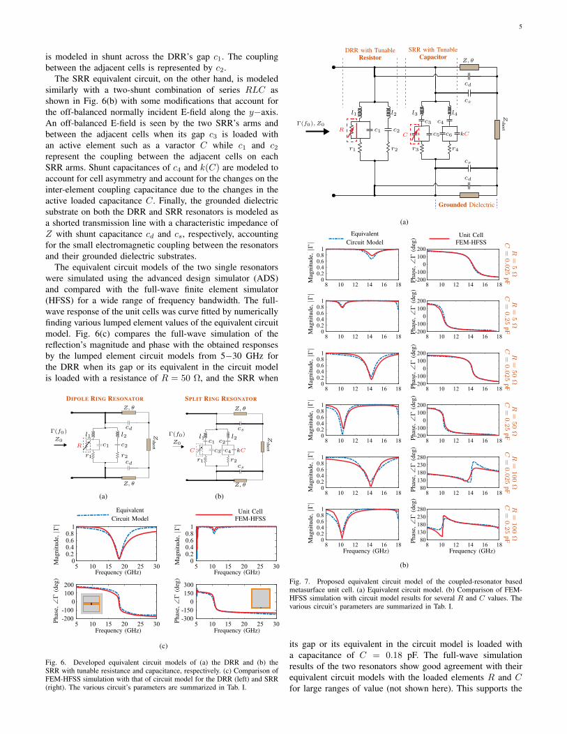
Fig. 14. Impact of the unit cell sizes on the lumped capacitor ranges. (a)Schematics of the top view showing the foot-print shapes of the two unitcell sizes of λ/10 and (b) λ/3.33, resepctively (schematics are not to scale).The simulation reflection magnitude and phase to illustrate the capacitancedynamic range for two different metasurface unit cell sizes of (b) λ/10 and(c) λ/3.33. operating at 10 GHz with a fixed lumped resistance R = 50 Ω.
It is also observed from the two-dimension contour viewsshown in Fig. 8 that the capacitance range increases (definedaround the valley region where the magnitude and phase varythe most) and moves towards larger values when operating atlower frequencies (longer wavelengths) for a fixed size unit cellwhile maintaining a similar coverage of independent reflectionmagnitudes and phases. This observation additionally suggeststhat larger capacitance values for a fixed operating frequencyrequire an electrically larger unit cell. Fig. 14 shows thesimulated reflection magnitude and phase at a fixed resistanceof R = 50 Ω for two different sizes unit cells of λ/10 and
λ/3.33, when the desired operating frequency is 10 GHz.To maintain a similar magnitude and phase coverage, thecapacitance values for the electrically larger unit cell (λ/3.33)is ranged between 0.3 − 2.2 pF while it is 0.165 − 0.31 pFfor the smaller cell. Therefore, if one chooses to use highercapacitance values in the design, the unit cell may becomelarger based on its size with respect to the wavelength whilemaintaining similar magnitude-phase coverage. Such a rela-tionship may be apparent through the cell geometries used inFig. 14, where a smaller inter-cell electromagnetic couplingdue to larger cell to cell separation in λ/3.33 case, couldbe compensated using a larger lumped element capacitance.While this brings the flexibility of using practical varactorelements exhibiting larger lumped capacitances (thus lesssensitive and economically cheaper), larger unit cell sizes maybe unfavorable since they sample the required spatially varyingamplitude/phase distributions poorly. Therefore, there existsa trade-off between lumped capacitor ranges and the spatialamplitude-phase discretization, where a judicious balance mustbe made in a practical metasurface design.
VI. CONCLUSION
A novel metasurface unit cell architecture has been proposedto enable independent control of the reflection magnitude andphase at a desired operating frequency while maintaining lin-ear polarization of the incoming fields. The proposed structureis based on a coupled-resonator configuration where a DRRloaded with PIN diode as a tunable resistive element andSRR loaded with a varactor diode as a tunable capacitor,are superimposed. The surface is next operated around oneof the coupled resonant frequency, where an independenttuning of the varactor and PIN diode elements enable a widecoverage of reflection amplitude-phase, which is significantlylarger than what would have been achievable using a singleresonator configuration. An insightful equivalent circuit modelhas also been developed for investigating the amplitude-phasecharacteristics of a uniform surface as a function of variableresistance and capacitance. Finally, using a variety of full-waveexamples, the usefulness of simultaneous and independentamplitude-phase control has been demonstrated, includingcases of variable pattern gain with beam tilting and multi-beampattern realization, which otherwise would not be possibleusing amplitude or phase control only.
This feature of independent phase control thus offers apractically useful mechanism to enable wave transformationwhich otherwise is not possible using existing conventionalapproaches, where either only amplitude or phase controlhas so far been shown. Since the proposed metasurface isbased on coupled-resonators loaded with separate lumpedelements, the biasing network is simple to design whereexternal voltage controls can be separately designed withminimal inter-dependence. While this work emphasized on theinner workings and exploring the electromagnetic propertiesof the proposed metasurface unit cell, the practical realizationwith external voltage biasing controls represent a standardtechnique for real-time control and thus pose no fundamentalissue. For instance, a practical metasurface structure can be

11
visualized having a pair of voltage controls per unit cell, sothat for a surface with N ×N unit cells, 2N2 voltage biasinglines can be used (for pixel-by-pixel control, or 2N controlsfor a row-by-row control). Moreover, an extension to multiplepolarization operations can be achieved using either a moresophisticated cell with full symmetry and an increased numberof resonators or devising a super-cell where the same cell is al-ternately rotated by 90. The surface thus subsequently can beinterfaced with control software that may provide convenientprogrammatic control of the surface, where different unit cellscan be independently assigned specific states, according to thedesired wave transformation requirements. The proposed meta-surface thus can be real-time reconfigured providing a versatilecontrol over the fields scattered off the surface while extendingtheir capabilities based on ML/AI may further be envisioned.Therefore, with flexible software programmable controls andenhanced reflection capabilities, the proposed metasurface maytruly be called a smart reflector with applications at the RF inthe area of wireless communication, sensing, and imaging.
REFERENCES
[1] C. L. Holloway, E. F. Kuester, J. A. Gordon, J. O’Hara, J. Booth,and D. R. Smith, “An overview of the theory and applications ofmetasurfaces: The two-dimensional equivalents of metamaterials,” IEEEAntennas Propag. Mag., vol. 54, no. 2, pp. 10–35, 2012.
[2] H.-T. Chen, A. J. Taylor, and N. Yu, “A review of metasurfaces: physicsand applications,” Rep. Prog. Phys., vol. 79, no. 7, p. 076401, 2016.
[3] H.-H. Hsiao, C. H. Chu, and D. P. Tsai, “Fundamentals and applicationsof metasurfaces,” Small Methods, vol. 1, no. 4, p. 1600064, 2017.
[4] X. Luo, “Principles of electromagnetic waves in metasurfaces,” Sci.China Phys. Mech. Astron., vol. 58, no. 9, p. 594201, 2015.
[6] A. Arbabi and A. Faraon, “Fundamental limits of ultrathin metasur-faces,” Sci. Rep., vol. 7, p. 43722, 2017.
[7] S. S. Bukhari, J. Y. Vardaxoglou, and W. Whittow, “A metasurfacesreview: Definitions and applications,” Appl. Sci., vol. 9, no. 13, p. 2727,2019.
[8] N. Yu, P. Genevet, M. A. Kats, F. Aieta, J.-P. Tetienne, F. Capasso, andZ. Gaburro, “Light propagation with phase discontinuities: generalizedlaws of reflection and refraction,” Science, vol. 334, no. 6054, pp. 333–337, 2011.
[9] M. A. Kats, D. Sharma, J. Lin, P. Genevet, R. Blanchard, Z. Yang, M. M.Qazilbash, D. Basov, S. Ramanathan, and F. Capasso, “Ultra-thin perfectabsorber employing a tunable phase change material,” App. Phys. Lett.,vol. 101, no. 22, p. 221101, 2012.
[10] D. Sievenpiper, L. Zhang, R. F. Broas, N. G. Alexopolous,E. Yablonovitch, et al., “High-impedance electromagnetic surfaces witha forbidden frequency band,” IEEE Trans. Microw. Theory Tech., vol. 47,no. 11, pp. 2059–2074, 1999.
[11] D. Sievenpiper, J. Schaffner, R. Loo, G. Tangonan, S. Ontiveros, andR. Harold, “A tunable impedance surface performing as a reconfigurablebeam steering reflector,” IEEE Trans. Antennas Propag., vol. 50, no. 3,pp. 384–390, 2002.
[12] R. Guzman-Quiros, J. L. Gomez-Tornero, A. R. Weily, and Y. J. Guo,“Electronically steerable 1-d fabry-perot leaky-wave antenna employinga tunable high impedance surface,” IEEE Trans. Antennas Propag.,vol. 60, no. 11, pp. 5046–5055, 2012.
[13] J. Sun, K. Chen, G. Ding, W. Guo, J. Zhao, Y. Feng, and T. Jiang,“Achieving directive radiation and broadband microwave absorption byan anisotropic metasurface,” IEEE Access, vol. 7, pp. 93 919–93 926,2019.
[14] C. Caloz and Z. Deck-Leger, “Spacetime metamaterials – part I: Generalconcepts,” IEEE Trans. Antennas Propag., vol. 68, no. 3, pp. 1569–1582,2020.
[15] S. Taravati and G. V. Eleftheriades, “Generalized space-time-periodicdiffraction gratings: Theory and applications,” Phys. Rev. Appl., vol. 12,p. 024026, Aug 2019.
[5] S. B. Glybovski, S. A. Tretyakov, P. A. Belov, Y. S. Kivshar, and C. R.Simovski, “Metasurfaces: From microwaves to visible,” Phys. Rep., vol.634, pp. 1–72, 2016.
[16] L. Zhang, S. Mei, K. Huang, and C.-W. Qiu, “Advances in full controlof electromagnetic waves with metasurfaces,” Adv. Opt. Mater., vol. 4,no. 6, pp. 818–833, 2016.
[17] S. L. Jia, X. Wan, P. Su, Y. J. Zhao, and T. J. Cui, “Broadbandmetasurface for independent control of reflected amplitude and phase,”AIP Adv., vol. 6, no. 4, p. 045024, 2016.
[18] G.-Y. Lee, G. Yoon, S.-Y. Lee, H. Yun, J. Cho, K. Lee, H. Kim, J. Rho,and B. Lee, “Complete amplitude and phase control of light usingbroadband holographic metasurfaces,” Nanoscale, vol. 10, pp. 4237–4245, 2018.
[19] L. Liu, X. Zhang, M. Kenney, X. Su, N. Xu, C. Ouyang, Y. Shi, J. Han,W. Zhang, and S. Zhang, “Broadband metasurfaces with simultaneouscontrol of phase and amplitude,” Adv. Mater., vol. 26, no. 29, pp. 5031–5036, 2014.
[20] K. Chen, Y. Feng, Z. Yang, L. Cui, J. Zhao, B. Zhu, and T. Jiang, “Ge-ometric phase coded metasurface: from polarization dependent directiveelectromagnetic wave scattering to diffusion-like scattering,” Sci. Rep.,vol. 6, no. 1, pp. 1–10, 2016.
[21] M. D. Renzo, M. Debbah, D.-T. Phan-Huy, A. Zappone, M.-S.Alouini, C. Yuen, V. Sciancalepore, G. C. Alexandropoulos, J. Hoydis,H. Gacanin, J. d. Rosny, A. Bounceur, G. Lerosey, and M. Fink, “Smartradio environments empowered by reconfigurable AI meta-surfaces: anidea whose time has come,” EURASIP J WIREL COMM, vol. 2019,no. 1, p. 129, 2019.
[22] X. Wan, M. Q. Qi, T. Y. Chen, and T. J. Cui, “Field-programmablebeam reconfiguring based on digitally-controlled coding metasurface,”Sci. Rep., vol. 6, p. 20663, 2016.
[23] H. Yang, X. Cao, F. Yang, J. Gao, S. Xu, M. Li, X. Chen, Y. Zhao,Y. Zheng, and S. Li, “A programmable metasurface with dynamicpolarization, scattering and focusing control,” Sci. Rep., vol. 6, p. 35692,2016.
[24] B. O. Zhu, J. Zhao, and Y. Feng, “Active impedance metasurface withfull 360 reflection phase tuning,” Sci. Rep., vol. 3, p. 3059, 2013.
[25] C. Liaskos, S. Nie, A. Tsioliaridou, A. Pitsillides, S. Ioannidis, andI. Akyildiz, “A new wireless communication paradigm through software-controlled metasurfaces,” IEEE Commun. Mag., vol. 56, no. 9, pp. 162–169, 2018.
[26] T. J. Cui, M. Q. Qi, X. Wan, J. Zhao, and Q. Cheng, “Codingmetamaterials, digital metamaterials and programmable metamaterials,”Light Sci. Appl., vol. 3, no. 10, pp. e218–e218, 2014.
[27] B. O. Zhu, K. Chen, N. Jia, L. Sun, J. Zhao, T. Jiang, and Y. Feng, “Dy-namic control of electromagnetic wave propagation with the equivalentprinciple inspired tunable metasurface,” Sci. Rep., vol. 4, no. 1, pp. 1–7,2014.
[28] L. Zhang, X. Q. Chen, S. Liu, Q. Zhang, J. Zhao, J. Y. Dai, G. D.Bai, X. Wan, Q. Cheng, G. Castaldi, et al., “Space-time-coding digitalmetasurfaces,” Nat. Commun., vol. 9, no. 1, pp. 1–11, 2018.
[29] M. Liu, A. B. Kozyrev, and I. V. Shadrivov, “Time-varying metasurfacesfor broadband spectral camouflage,” Phys. Rev. Appl., vol. 12, no. 5, p.054052, 2019.
[30] C. Qian, B. Zheng, Y. Shen, L. Jing, E. Li, L. Shen, and H. Chen,“Deep-learning-enabled self-adaptive microwave cloak without humanintervention,” Nat. Photon., vol. 14, no. 6, pp. 383–390, 2020.
[31] E. Carrasco, M. Tamagnone, and J. Perruisseau-Carrier, “Tunablegraphene reflective cells for thz reflectarrays and generalized law ofreflection,” App. Phys. Lett., vol. 102, no. 10, p. 104103, 2013.
[32] A. Z. Ashoor and S. Gupta, “Towards real-time independent controlof reflection magnitude and phase in electromagnetic metasurfaces,”in 2020 14th European Conference on Antennas and Propagation(EuCAP), Mar. 2020, pp. 1–4.
[33] S. Han, S. Kim, S. Kim, T. Low, V. W. Brar, and M. S. Jang, “Completecomplex amplitude modulation with electronically tunable grapheneplasmonic metamolecules,” ACS Nano, vol. 14, no. 1, pp. 1166–1175,Jan. 2020.
[34] F. Costa, A. Monorchio, and G. Manara, “An overview of equivalentcircuit modeling techniques of frequency selective surfaces and metasur-faces,” Appl. Comput. Electromagn. Soc. J., vol. 29, no. 12, pp. 960–976,2014.