Embed Size (px)
Citation preview

1547 N. Trooper Road • P. O. Box 1117 • Worcester, PA 19490-1117 USA Corporate Phone: 610-825-4990 • Sales: 800-832-4866 or 610-941-2400
Fax: 800-854-8665 or 610-828-5623 • Web: www.techni-tool.com
Surface Mount Removal Techniques Using MX-5200 Soldering & Rework System
Our thanks to Metcal for allowing us to reprint the following.
ABSTRACT
This Technical Note outlines, step by step, the easiest ways to remove and replace surface mount devices, using the lowest possible temperatures with an MX-5200 Soldering and Rework System.
Specifically, this document discusses:
Removal and replacement of discrete and passive components (capacitors, resistors, SOTs)
Removal of two-sided components (SOICs, SOJs, TSOPs)
Removal of quad components (PLCCs, QFPs)
Replacement of quad components including fine-pitched devices
These tasks can all be accomplished using a Metcal Advanced™ Handpiece (MX-H1-AV) or standard MX-500 MX-RM3E Hand-piece in conjunction with the MX-5200. Removal of some components may also be achieved using Metcal's MX-PTZ Hand-piece, or the MX-H2-UF Metcal UltraFine™ Hand-piece which uses UltraFine™ soldering cartridges (UFTC).
Skills and techniques are designed to provide even the least experienced operator the power to perform some of the most difficult rework tasks in electronics today. By using lower temperatures, SmartHeat® Technology offers a means of rework that is safer for today's smaller, densely populated, heat sensitive circuit boards and components.
REMOVING DISCRETE AND PASSIVE COMPONENTS Removing a CHIP CAP With a Metcal MX-H1-AV Advanced™ Hand-piece
The Metcal systems offer a wide range of surface mount cartridges to remove small, discrete components such as 0805, 1206, 1210, 1808, 1812 or SOT-23. Metcal calls these cartridges their “slot cartridges" and in most cases the slot is sized to match the lead width of the component. You must match the correct cartridge with the component you are removing. In a few cases, the slot of a larger cartridge can be tinned with wire solder to fill the void allowing it to be used to remove a component whose footprint is slightly smaller.
1. Choose the correct cartridge from the list below:

1547 N. Trooper Road • P. O. Box 1117 • Worcester, PA 19490-1117 USA Corporate Phone: 610-825-4990 • Sales: 800-832-4866 or 610-941-2400
Fax: 800-854-8665 or 610-828-5623 • Web: www.techni-tool.com
2. Choose the correct cartridge temperature for the
removal task. When choosing the temperature, it is always best to choose the lowest temperature possible to accomplish the job. Metcal offers cartridges in 500, 600, 700 and certain 800 Series heaters. In most lead free cases, a 600 Series cartridge is sufficient to do the job. An exception would be when the printed circuit board (PCB) has a heavy ground plane and the component circuitry, or traces, are attached to that plane. In this case, use a 700 Series. If you think you need a 800 Series cartridge, call your local Metcal Representative or Distributor to be sure that your application warrants it. With the correct geometry 700 series should work even with lead free applications.
3. Metcal's slot cartridges may take 10-20 seconds to
heat to their designed temperature using the MX-5200 power supply. After allowing the cartridge to heat, tin the inside edges of the cartridge. Tinning the inside performs two functions. First, it assists heat delivery for quicker removal. Second, the solder on the inside edges will help pick the component off the board once it is reflowed.
4. Bring the cartridge down directly over the fluxed
component so the inside edges make direct contact with the leads of the part.
5. Allow the cartridge to reflow the solder completely
on both sides of the component. This requires a minimal degree of skill and judgment.
6. When you are certain it is completely reflowed,
slightly twist the cartridge slightly in a circular motion and lift simultaneously. This action is necessary to
break the surface tension bond of the solder or glue that has been holding the component to the lands.
By being patient and allowing sufficient time for the solder joints to reflow completely, you reduce your risk of lifted pads. On the smaller discrete components, this generally means just two to three seconds. However, many printed circuit boards now have components mounted on both the top and bottom. When discrete components are mounted on the bottom of a PCB, they are usually secured with a chip-bonder epoxy. This will cause reflow to take a few seconds longer. Now you not only have to reflow the solder joints, but you must also melt or soften the epoxy by transferring the heat through the body of the component.
Don't worry. The additional reflow time is never more than a couple of seconds. 7. After you have removed the component off the
board, wipe it on the wet sponge or brass tip cleaning pad to dislodge it from the cartridge. Do not tap the cartridge on the workstand, as that may cause damage to the heater in the cartridge.
Removing CHIP CAP’s with a MX-PTZ Precision Tweezers Hand-piece The MX-PTZ Precision Tweezers offer a versatile option for removal of components with the PTTC Series of cartridges from 0.4mm tip to 7mm tips.
Select the correct tweezers cartridges from the chart below (note these are fine tips, 0.4mm – 1.27mm):
Please see the “Cartridges Part Number Code System” chart for temperature designation and geometry.
1547 N. Trooper Road • P. O. Box 1117 • Worcester, PA 19490-1117 USA Corporate Phone: 610-825-4990 • Sales: 800-832-4866 or 610-941-2400
Fax: 800-854-8665 or 610-828-5623 • Web: www.techni-tool.com
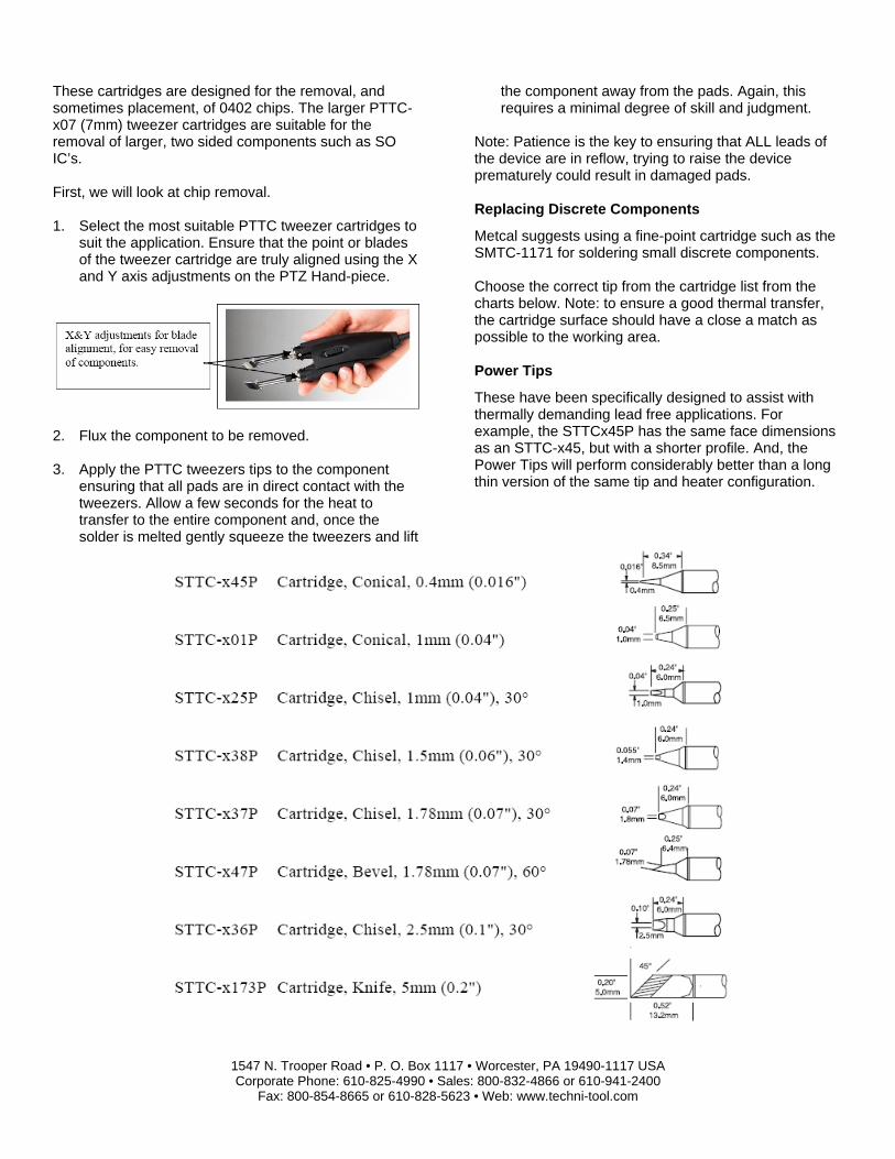
These cartridges are designed for the removal, and sometimes placement, of 0402 chips. The larger PTTC-x07 (7mm) tweezer cartridges are suitable for the removal of larger, two sided components such as SO IC’s. First, we will look at chip removal. 1. Select the most suitable PTTC tweezer cartridges to
suit the application. Ensure that the point or blades of the tweezer cartridge are truly aligned using the X and Y axis adjustments on the PTZ Hand-piece.
2. Flux the component to be removed. 3. Apply the PTTC tweezers tips to the component
ensuring that all pads are in direct contact with the tweezers. Allow a few seconds for the heat to transfer to the entire component and, once the solder is melted gently squeeze the tweezers and lift
the component away from the pads. Again, this requires a minimal degree of skill and judgment.
Note: Patience is the key to ensuring that ALL leads of the device are in reflow, trying to raise the device prematurely could result in damaged pads. Replacing Discrete Components
Metcal suggests using a fine-point cartridge such as the SMTC-1171 for soldering small discrete components. Choose the correct tip from the cartridge list from the charts below. Note: to ensure a good thermal transfer, the cartridge surface should have a close a match as possible to the working area. Power Tips
These have been specifically designed to assist with thermally demanding lead free applications. For example, the STTCx45P has the same face dimensions as an STTC-x45, but with a shorter profile. And, the Power Tips will perform considerably better than a long thin version of the same tip and heater configuration.

1547 N. Trooper Road • P. O. Box 1117 • Worcester, PA 19490-1117 USA Corporate Phone: 610-825-4990 • Sales: 800-832-4866 or 610-941-2400
Fax: 800-854-8665 or 610-828-5623 • Web: www.techni-tool.com
Chisel Cartridges * Indicates a power version of this tip exists in above chart.
Bevel Cartridges * Indicates a power version of this tip exists in above chart.
Please see the “Cartridges Part Number Code System” chart for temperature designation and geometry. Working with Ceramic Capacitors and Sensitive Components
You should select the lowest temperature cartridge possible to achieve the required solder joint when working with ceramic parts. Ceramics are more susceptible to thermal shock and by following a few simple steps you can virtually eliminate this risk to your components. In addition, by using a lower temperature cartridge, you will significantly increase your cartridge life. If any thermal challenges are found, and the temperature of the tip needs to be kept low, use a convection preheater such as the PCT-1000 Programmable Preheater or PCT-100 Focused Convection Preheater to provide supplemental heat energy from the bottom of the PCB as shown later in this document.
The use of bottom side preheating will aid reflow considerably with 500 and 600 series heater cartridges. For those that need to active a low solder joint temperature for sensitive chip components under 265°C- 270°C (509°F-518°F) this can be evaluated with 500 series tips and preheater.
1. Clean the old solder from the pads of the component you just removed. Use a standard chisel or hoof tip soldering cartridge which best suits the pad size and a suitable solder braid. The ideal size tip. The closer the match in size increases thermal transfer and reduces the potential of abrasion to the PCB Solder resist.
2. Apply flux to the pads to ensure that the pads are free from oxidization and other contaminates.

1547 N. Trooper Road • P. O. Box 1117 • Worcester, PA 19490-1117 USA Corporate Phone: 610-825-4990 • Sales: 800-832-4866 or 610-941-2400
Fax: 800-854-8665 or 610-828-5623 • Web: www.techni-tool.com
3. Place the new component, holding it in place with a pair of tweezers or wooden stick (tooth picks / orangewood sticks are used by some operators).
4. Use a fine point cartridge to solder the leads to the pads. The cartridge should be placed at the junction where the lead meets the pad. This is the correct IPC method for making the solder joint and it allows the cartridge to ramp up the temperature of the component. Avoid placing the cartridge directly on the lead; placing the cartridge on the lead may thermally shock the component, or take longer than necessary to transfer the heat to the pad. Place the tip between the part and the pad and apply solder to the two points. Solder must not flow over the top of the chip components.
5. After you have made the first solder joint, check
component alignment and solder the other leads in the same manner.
REMOVAL OF SOIC’s, SOJ’s, AND TSOP’s using the Metcal Advanced™ Handpiece (MX-H1-AV) or MX-RM3E (standard MX-500 hand-piece) Removing multi-leaded two sided components is very similar to removing discrete components when using SMTC tips. The choice of cartridge, however, is more crucial. Each SMTC removal cartridge that Metcal makes is component specific. If you remove many different two-sided components every day, you may want to consider using the MX-PTZ Precision Tweezers, which will work with both the MX-500P and MX-PS5200 Power Supplies.
Select the correct cartridge from the list below
Item Description Dim A mm (") Dim A2 mm (") Dim B mm (") Dim D mm (") SMTC-x42 Cartridge, Tunnel, SOIC-32 13.21 (0.520) 13.21 (0.520) 20.45 (0.805) 3.18 (0.125)
SMTC-x06 Cartridge, Tunnel, SOIC -14, 16 5.08 (0.200) 5.08 (0.200) 10.16 (0.400) 2.30 (0.90)
SMTC-x04 Cartridge, Tunnel, SOIC -8 5.08 (0.200) 5.08 (0.200) 4.32 (0.170) 2.30 (0.90)
SMTC-x142 Cartridge, Tunnel, SOIC -14 5.18 (0.204) 5.18 (0.204) 8.90 (0.350) 2.50 (0.100)
SMTC-x20 Cartridge, Tunnel, SOMC-16 6.86 (0.270) 6.86 (0.270) 11.18 (0.440) 2.30 (0.090)
SMTC-x138 Cartridge, Tunnel, SOP-20 6.86 (0.270) 6.86 (0.270) 7.24 (0.285) 2.50 (0.100)
SMTC-x124 Cartridge, Tunnel, SOJ-16 8.13 (0.320) 8.13 (0.320) 11.94 (0.470) 6.86 (0.270)
SMTC-x47 Cartridge, Tunnel, DPAK 8.50 (0.335) 8.50 (0.335) 6.35 (0.250) 5.00 (0.200)
SMTC-x26 Cartridge, Tunnel, SOJ-28, SOM-36 8.64 (0.340) 8.00 (0.315) 18.80 ( 0.740) 1.88 (0.074)
SMTC-x10 Cartridge, Tunnel, SOIC -20 9.53 (0.375) 9.53 (0.375) 13.20 (0.520) 3.20 (0.125)
SMTC-x09 Cartridge, Tunnel, SOIC -24 9.53 (0.375) 9.53 (0.375) 15.75 (0.620) 3.20 (0.125)
SMTC-x07 Cartridge, Tunnel, SOIC -28 9.53 (0.375) 9.53 (0.375) 18.30 (0.720) 3.20 (0.125)
SMTC-x107 Cartridge, Tunnel, SO-8 9.65 (0.380) 8.10 (0.320) 19.00 (0.750) 6.10 (0.240)
SMTC-x40 Cartridge, Tunnel, SOJ-40. SOM-32 11.43 (0.450) 10.40 (0.410) 25.90 (1.02) 1.90 (0.075)
SMTC-x83 Cartridge, Tunnel, SOP-44 14.35 (0.565) 12.95 (0.510) 27.18 (1.07) 2.70 (0.105)
Please see the “Cartridges Part Number Code System” chart for temperature designation and geometry.
1. Choose the correct cartridge temperature. Again, Metcal makes different temperature Series for these removal cartridges, but we suggest using a 600 or 700 Series heaters for most applications. Exceptions would be heavy ground plane boards or components that are much larger and more dense. If 800 series cartridges are selected, tip life will be shorter and good tip care is essential, See Metcal tip care guide
(the use of a convection preheater PCT 100 or PCT 1000 should also be considered as opposed to 800 series heaters.) Preheating a FR-4 PCB to 60-80ºc, will increase productivity and lower the required tip temperature which is safer for the application and increases tip life. Preheating ceramic or military substrates to 100ºC and polyimide PCBs to 120ºC will increase productivity and allow lower soldering

1547 N. Trooper Road • P. O. Box 1117 • Worcester, PA 19490-1117 USA Corporate Phone: 610-825-4990 • Sales: 800-832-4866 or 610-941-2400
Fax: 800-854-8665 or 610-828-5623 • Web: www.techni-tool.com
cartridge temperatures to be selected, protecting the PCB as well as increasing tip life.
2. After inserting the cartridge and allowing it to heat,
fully tin the inside edges of the cartridge with wire solder. Apply flux to the component leads.
3. Bring the cartridge straight down on top of the leads
of the component. Make sure that you have contact with all the leads.
4. Leave the cartridge on the leads without rocking or twisting the cartridge on the component. An approximate time would be two second to 8 seconds for removal. Patience is the key to not lifting a pad.
5. Once you are certain all leads are reflowed, use a
slight twisting and wiping motion to remove the component off the board. The surface tension of the
cartridge's tinned edges will hold the component in the cartridge.
6. Wipe the component on the Damp sponge or brass
pad to dislodge it from the cartridge. 7. Re apply solder to tin the tip before replacing it in the
stand to reduce oxidization of the soldering surfaces.
REMOVING SOIC’s, SOJ’s, AND TSOP’s WITH THE MX-PTZ PRECISION TWEEZERS 1. Select the most suitable PTTC Tweezer Cartridges
to suit the component to be removed from the chart below. These are large tip tweezers 2mm – 28mm
Ensure that the blades are truly aligned using the X and Y axis adjustments on the MX-PTZ Hand-piece as shown previously on page 3.
2. Flux the component to be removed. Gel flux is also a good option to consider in fine rework applications as it aids in the transfer of heat to the component faster than liquid flux, this is because of better
surface coverage on leads than liquid flux. Gel flux is available from most solder paste suppliers
3. Do not mix “lead-free” and “leaded” fluxes (lead-free PCB reworked with leaded flux, will contaminate the PCB, you must use lead-free flux used with lead-free solder wick). If flux types are mixed, contamination can occur and undesirable residues left on the PCB, which can be difficult to remove and may become
Please see the “Cartridges Part Number Code System” chart for temperature designation and geometry.

1547 N. Trooper Road • P. O. Box 1117 • Worcester, PA 19490-1117 USA Corporate Phone: 610-825-4990 • Sales: 800-832-4866 or 610-941-2400
Fax: 800-854-8665 or 610-828-5623 • Web: www.techni-tool.com
conductive or aggressive with age. Sometimes this is shown as a white powder like material left on surface of PCB.
4. Apply the PTTC Tweezers to the component ensuring that all leads are in direct contact with the tweezers. Allow a few seconds for the heat to transfer to the entire component and, once in reflow, gently squeeze the tweezers and lift the component away from the PCB. Again, this requires a minimal degree of skill and judgment.
Note: Patience is the key to ensuring that all leads of the device are in reflow, trying to raise the device
prematurely could result in damaged pads. An arm rest is also a useful tool. This is available as a separate tool for use with irons or tweezers. Using a preheater to aid removal when using tweezers or tunnel tips will decrease time on the component and lower temperature tips can be used.
PCT-AR Arm rest is a useful tool, available separately.
PAD CLEAN UP AND PREPARATION The following steps may be used for both two and four-sided components regardless of the lead configuration or pitch. You may use a blade cartridge in conjunction with solder braid to clean off the pads. Never use a solder cartridge or a blade with wick by dragging it down the row of pads with heavy pressure. The heat combined with the abrasive action of the wick may cause the epoxy holding the pads on the board to soften resulting in a lifted pad or trace. Once again the use of a preheater will allow lower temperature tips to be used, reducing potential damage, especially on large PCBs or large BGA matrices. 1. Metcal makes a range of SMTC blade cartridges for
cleaning the old solder off the pads. Choose the size of blade cartridge that best fits the row of pads. Hoof tips are also used frequently and work well for small area clean up. Use as low a temperature cartridge as the PCB will allow. Selecting a higher temperature series cartridge will not necessarily
remove the old solder more quickly, and the excess heat may burn the board or lift a pad. The power of the MX-5200 System will allow you to use lower temperatures than other soldering systems, and it is recommended to use the MX-5200 with 600 or 700 series cartridges and a preheater.
2. Flux the PCB and when BGA pad cleaning, first wipe
the blade over the pads lightly to dome the pads to form a round dome (removing any spikes) before using solder wick. If the wick is pushed against a solder spike before solder melts this can cause pad crater or a lifted pad. For more information contact OkI for the PowerPoint on BGA Cleaning process improvements.
3. Additional flux may be required after the initial
doming of the pads to ensure proper and efficient solder removal with the wick.
4. Also, adding gel flux to solder wick will increase
performance considerable as this increase capillary action of solder being sucked into the wick.
PCT 100 Convection Preheater

1547 N. Trooper Road • P. O. Box 1117 • Worcester, PA 19490-1117 USA Corporate Phone: 610-825-4990 • Sales: 800-832-4866 or 610-941-2400
Fax: 800-854-8665 or 610-828-5623 • Web: www.techni-tool.com
5. Lay the wick along the row of pads. 6. Bring the blade down on the wick and give it two or
three seconds to melt the solder. Using the beveled edge of the blade cartridge gives better surface contact and will make the job quicker.
7. Gently wipe the solder across the array of pads
working the wick towards the inside of the component pattern. No pressure is required as the SmartHeat® cartridge will maintain its temperature.
Conventional soldering systems lose temperature which cools the tip, in turn operators tend to add additional pressure to clean pads, this is what damages solder resist and causes pad crater and pad lift.
8. If the row of pads is longer than the blade, repeat
this process for the remaining pads. 9. Repeat all of the above steps for each side of the
pad array. Process Tip - Cut off excess wick each time cleaning is done, or the solder that will remain on the wick can attach to adjacent components causing damage or additional rework. This can also cause burns to the operator. Remember, cut the excess wick off when it is fully absorbed with solder. REPLACING TWO AND FOUR-SIDED COMPONENTS Metcal makes a number of hoof cartridges for replacing multi-leaded components. The particular hoof should be selected depending on the number of leads or the lead pitch. The hoof cartridge is designed to solder a number of leads simultaneously by depositing solder directly on the face of the cartridge. Once you’ve practiced a bit, you will find it is the easiest and fastest way to solder multi-leaded components.
One third tinned hoof One Half tinned hoof
Replacing Standard Pitch SOIC and Gull Wing Components
1. Align the component to the pads on the board.
2. Making sure the number one lead is lined up with the number one pad, align the leads with the pads. Directly centre the leads onto the pads.
3. Holding the component steady with one hand, flux
the opposing corner leads of the PCB. 4. Place enough solder onto the face of the cartridge
so that it covers about one third of the cartridge. Keep the solder down towards the "toe" of the cartridge.
5. Bring the cartridge down and "paint" the leads where
you applied the flux. The object here is to tack the part down, not make good solder joints.
6. Wipe the excess solder from the cartridge. 7. Make sure that the face of the hoof is shiny and
wettable. You will not get good results if the cartridge is oxidized. If solder balls up on the face you need to tin the cartridge. Once the cartridge is tinned and shiny the solder should flow on the cartridge.
8. Apply enough solder to cover approximately one-half
of the cartridge. The amount of solder will vary with the number of leads you have. For fewer leads apply less solder.
9. Flux an entire row of leads at a time. Work with the
row of leads going from left to right in front of you. Work from left to right if you are right handed and vice-versa.
10. Hold the cartridge so the toe of the hoof runs parallel
along the row of leads. 11. Bring the cartridge in on a flat landing onto the first
lead. Immediately begin running the cartridge down the row of leads drawing a straight line.
12. When you reach the end, wipe the cartridge down
the lead towards you. It is common for the last two pins to bridge. To remove a bridge, place tip on last two pins and wipe at 90º to leads outwards, the bridge will be removed. If not, apply flux and try again.
13. Repeat these steps for each row of leads. Note: The angle of the cartridge should be parallel, but can be up to 30º for good results. If the toe of the hoof is the front, then the right side should make contact right at the bend of the leg of the lead. It should be held in that position for the entire process. If you are left-handed, it will be just the opposite.

1547 N. Trooper Road • P. O. Box 1117 • Worcester, PA 19490-1117 USA Corporate Phone: 610-825-4990 • Sales: 800-832-4866 or 610-941-2400
Fax: 800-854-8665 or 610-828-5623 • Web: www.techni-tool.com
The speed is more crucial than the angle. The speed should be steady and slow enough to deposit the solder from the cartridge onto each of the leads as you draw it across. An approximate time is one second per lead. As you get more comfortable with the procedure, the speed gets less crucial. Replacing Fine Pitch Gull Wing Components
Drag solder method with blade tip
1. Alignment of fine pitch components can be tricky. Take your time to ensure proper alignment. It will make all the difference in your successful application of this technique. After alignment, tack the component as you would for a standard pitch part. Use a little less solder on the end of the cartridge for "painting" the leads.
2. Working with one row of leads at a time, apply flux to an entire row of leads.
3. Wipe all excess solder from the face and top of the cartridge and start with fresh solder.
4. Apply enough solder on the tip to use for one wipe of one complete side of that component. Not only will the number of leads vary the amount of solder, but the pitch of the leads will also. The finer the leads, the less solder you will need, if more solder is needed this should be repeated or added to tip during first wipe, some operators prefer to add more solder while wiping back and forth with a generous amounts of flux on the leads.
5. Immediately start drawing the cartridge down the row of leads until you reach the end. Do not stop and restart or you will get bridging.
6. Remember to hold the cartridge parallel to the leads or up to 30° and to keep it at the end of the leads.
7. As the pitch gets finer, you can work faster. But don't work too fast or you will get good toe solder joints but poor heel joints as the solder will not have time to flow under lead.
Good Joints
Lead Free Pb Lead
Heel Toe Heel Toe 8. Repeat the steps for all sides of the component. Point to point method soldering Select the appropriately sized conical or bent conical tip to suit the pitch of the component being reworked. This can be a straight or conical cartridge depending on your preference.
1. Align the component into place, apply flux to 2 corners and tack into position.
2. Apply flux to an entire row of leads.
3. Working on one point at a time, apply the cartridge onto the toe of the lead and wipe the cartridge outwards. Repeat for each point.
4. Use a small conical or bent conical tip.
5. Cover the lead with half the width with solder wire. Wipe tip inwards from edge of pad with tip touching pad.
6. As tip touches solder it will flow solder to the leads.

1547 N. Trooper Road • P. O. Box 1117 • Worcester, PA 19490-1117 USA Corporate Phone: 610-825-4990 • Sales: 800-832-4866 or 610-941-2400
Fax: 800-854-8665 or 610-828-5623 • Web: www.techni-tool.com
Removing Shorts between Gull Wing Leads
Your chances of getting shorts or bridges between leads are greatly increased as the distance between the leads gets smaller. Working with fine pitch leads requires more skill and experience whether you are reworking with one of Metcal's hoof cartridges or any other type of equipment. Removal of these shorts is very simple following these steps. 1. Use Metcal's SMTC-x167 or a suitable sized hoof
cartridge from the chart above.
Note: Having more heat at the cartridge makes removing shorts more difficult.
2. Apply flux to the bridged leads.
3. Wipe all excess solder from the face and the top of the Hoof cartridge.
4. Make sure the cartridge is shiny and wettable.
5. Bring the cartridge in with the flat surface, making contact with the bridge; again holding the cartridge parallel to the leads at a 30º angle to the PCB.
6. Wipe the bridge outwards and away from the component.
7. The excess solder on the joints will go naturally to the heat source - the cartridge. Look at the face of the hoof and you should see the excess solder.
8. If you did not get all of the bridge on the first try, wipe the excess solder from the cartridge and repeat the procedure and add additional flux.
9. If the bridge is extreme you can use your blade cartridge. First, wipe the blade free of solder on both edges. Then, using the beveled edged down, wipe the blade in the same manner down the fluxed leads.
10. For bridges on fine pitch components, the use of solder wick dipped into liquid flux can be an effective method of removal. Simply place the wick on the bridge, apply the soldering tip onto the wick, allow the solder to melt and flow into the wick and remove both together.
11. For very fine pitched applications, form the wick into
a fine point and apply heat via soldering tip to the wick not the component lead. The solder will travel by capillary action away from the bridge.
When performing these steps, if you leave the heat on the leads too long, the shorts will want to stay. This occurs when you have heated the leads and pads too much, causing them to act as the heat source instead of the cartridge. If this happens, allow the leads to cool down a little. Then try the procedure again. REMOVING FOUR-SIDED COMPONENTS Removing larger component packages will generally require more heat and the use of flux for the best and fastest results. In the two steps below; the application of flux and the wrapping of wire solder are optional. You should check your written procedures to see if these steps are permitted. Select the correct SMTC cartridge from the chart below
B2
B
A A2
D
Item Description Dim A2 mm (") Dim A mm (") Dim B2 mm (") Dim B mm (") Dim D mm (") SMTC-x118 Cartridge, Quad, VQFP-100 14.48 (0.570) 15.49 (0.610) 14.48 (0.570) 15.49 (0.610) 2.79 (0.110)
SMTC-x12 Cartridge, Quad, PLCC-20 9.14 (0.360) 10.16 (0.400) 9.14 (0.360) 10.16 (0.400) 3.80 (0.150)
SMTC-x120 Cartridge, Quad, SQFP-64 11.18 (0.440) 11.18 (0.440) 11.18 (0.440) 11.18 (0.440) 2.54 (0.100)
SMTC-x121 Cartridge, Quad, SQFP-48 8.38 (0.330) 8.38 (0.330) 8.38 (0.330) 8.38 (0.330) 2.54 (0.100)
SMTC-x13 Cartridge, Quad, PLCC-28 11.56 (0.455) 12.70 (0.500) 11.58 (0.455) 12.70 (0.500) 3.80 (0.150)
SMTC-x14 Cartridge, Quad, PLCC-44 16.76 (0.660) 17.78 (0.700) 16.76 (0.660) 17.78 (0.700) 3.80 (0.150)
SMTC-x159 Cartridge, Quad, TQFP-44 11.18 (0.440) 12.19 (0.480) 12.19 (0.480) 13.21 (0.520) 2.79 (0.110)
SMTC-x16 Cartridge, Quad, PLCC-32 11.43 (0.450) 12.70 (0.500) 13.97 (0.550) 15.24 (0.600) 3.81 (0.150)
SMTC-x17 Cartridge, Quad, PLCC-52 19.30 (0.760) 20.32 (0.800) 19.30 (0.760) 20.32 (0.800) 3.81 (0.150)
SMTC-x21 Cartridge, Quad, QFP-44 16.13 (0.635) 16.13 (0.635) 16.13 (0.635) 16.13 (0.635) 3.30 (0.130)
Please see the “Cartridges Part Number Code System” chart for temperature designation and geometry.

1547 N. Trooper Road • P. O. Box 1117 • Worcester, PA 19490-1117 USA Corporate Phone: 610-825-4990 • Sales: 800-832-4866 or 610-941-2400
Fax: 800-854-8665 or 610-828-5623 • Web: www.techni-tool.com
1. This is the one time Metcal suggests using higher
temperature 700 or 800 series cartridges; it will make a tremendous difference in removal time. Remember: it is not only the temperature you put on the board that counts. It is the temperature plus the amount of time it is left on there that makes the difference. By removing the component faster, you reduce the chances of thermal damage.
2. If the component cannot be removed easily in 10-15
seconds then this may cause excessive heating of the component leads and might result in a pad being lifted or damaged more easily.
The use of a convection preheater can reduce the temperature and the process time if parts and substrate are thermally demanding; preheat the FR-4 PCB to 60-80°C and polyimide, ceramic and military substrates 100-120°C.
Example below
3. Allow the cartridge to heat fully. This is important, because if it is not up to full temperature your removal time will be increased.
4. Tin all inside edges of the cartridge. Just like your
blade or hoof cartridge, the removal cartridges must remain shiny and wettable. If you try removing a component with a cartridge that is partially oxidized the reflow will take longer. This increases the chances of lifting pads because you will see some leads being reflowed appropriately. Those leads will be the areas of the cartridge that were tinned. The sections of the cartridge that were oxidized will take longer to reflow and you may lift pads trying to remove the component before it is ready.
NOTE: If your cartridge is oxidized, or if there are flux residues prohibiting you from tinning the cartridge, use a brass brush (AC-BRUSH) to clean the inside edges. Heat the cartridge and wipe edges with the brush.
5. Flux all sides of the component. 6. Take some wire solder (.025 or .031 works best) and
wrap it around the leads of the component. On J-leaded components this step is easy. The wire will wrap easily around the leads and stay in place.
On gull-winged parts it is a little more difficult. Here's a hint. Try sticking the end of the solder behind the legs on one corner of the component and anchor the wire there. Then wrap the wire around the outside of the legs. This will help hold it in place.

1547 N. Trooper Road • P. O. Box 1117 • Worcester, PA 19490-1117 USA Corporate Phone: 610-825-4990 • Sales: 800-832-4866 or 610-941-2400
Fax: 800-854-8665 or 610-828-5623 • Web: www.techni-tool.com
7. Bring the cartridge straight down on top of the part,
making full contact on all four sides of the leads. 8. Hold the cartridge in place without moving back and
forth or rocking for about 10-15 seconds. Once you practice this step a little, you will get a feel for the reflow and you will actually find it to be a little faster.
9. When you are certain you have full reflow, twist the
handle between your thumb and forefinger just slightly. If you do have complete reflow you will feel the component move. If you do not, the cartridge will twist in the handle. This is a built in mechanism to prevent you from removing a component that is not ready, thereby decreasing the chances for lifting pads.
10. If you feel the component move, wipe it to one side
just slightly and lift simultaneously. The component should be held in the tinned cartridge with surface tension. Some operators also use manual tweezers as a lifting aid.
11. Remove the component immediately by wiping it on
the sponge or the brass tip cleaning pad. REPLACING J-LEADED COMPONENTS WITH A KNIFE TIP
If components are too tightly packed for access with the hoof tip, you may need to use one of Metcal’s knife cartridges:
SMTC-x172 Cartridge, Hook, Long, 0.5mm (0.02") SMTC-x171 Cartridge, Conical, Bent, 0.76mm (0.03") SMTC-x161 Cartridge, Knife, Thin Tin Length, 4.8mm (0.18") SMTC-x173 Cartridge, Knife, Wide Tin Length, 4.8mm (0.18") Please see the “Cartridges Part Number Code System” chart for temperature designation and geometry.
Doing multi-lead soldering of J-leaded components is best achieved with the knife cartridge. First, you’ll need to tack the component in place. Follow these steps:
1. Flux the pads on opposing corners.
2. Make sure your cartridge is clean and wettable and apply solder to the bottom edge of the knife tip only on the side that will contact the leads.
3. Align the component to the board – number one lead
to number one pad. 4. Bring the cartridge in with the toe flat, meeting the
lead and the fluxed pad at the same time. 5. Continue to hold the part with the finger and repeat
this for the opposite corner pads. 6. Now the component should be fixed firmly on at
least two corners. The solder joints won’t look good, but their function is merely to hold the component while soldering. Now you are ready to solder. Work with one side at a time.
7. Wipe the tip free of excess solder. You need to
make sure that the tip is shiny and wettable. 8. Apply solder to the bottom edge of the knife
cartridge only on the side that will contact the leads. 9. Apply flux to the rest of the pads to be soldered on
that side. 10. Work with the component leads in front of you going
from left to right. If you are right handed start soldering from the far left lead. If you are left handed, work in reverse.
11. Bring the cartridge with the bottom edge in light
contact with the pads, tilting in under the leads a little bit if possible. Err to the side of tilting the heel of the knife up a little bit to avoid catching the edge of a pad with it. The flatter the knife is to the board, the better the solder joint will be.
12. You will see the solder wick right down the leads,
depositing an even amount to each lead. It will appear to short until you draw the tip down the row further. If the right amount of solder is used at the right speed then there should be no shorts.
13. If you added too little solder to the cartridge, you
may run out before you reach the end of the row. If this happens, flux from where you ran to the end of the row, apply some further solder to the bottom of the knife and continue the process from where you left off.
Removing Shorts from J-Leaded Components
1. Apply flux to the bridged leads.

1547 N. Trooper Road • P. O. Box 1117 • Worcester, PA 19490-1117 USA Corporate Phone: 610-825-4990 • Sales: 800-832-4866 or 610-941-2400
Fax: 800-854-8665 or 610-828-5623 • Web: www.techni-tool.com
2. Wipe all solder from the knife face. 3. Bring the knife cartridge in with the face flat on the
pad and lift vertically. Repeat until all bridges are removed.
Reworking Ultra Fine Devices on Densely Populated Boards
With the size of components becoming smaller, the requirement for precision soldering is increasingly important. As a solution, Metcal developed the UltraFine™ Hand-piece and UFTC cartridges (Ultra fine Tip Cartridge). The hand-piece and cartridges are around 1/3 the size of the standard MX-RM3E handpiece and STTC cartridges, allowing for access to the most intricate PCB’s without compromising performance.
Please see the “Cartridges Part Number Code System” chart for temperature designation and geometry.

1547 N. Trooper Road • P. O. Box 1117 • Worcester, PA 19490-1117 USA Corporate Phone: 610-825-4990 • Sales: 800-832-4866 or 610-941-2400
Fax: 800-854-8665 or 610-828-5623 • Web: www.techni-tool.com
The UFTC fine tip cartridges are very useful for reworking ultra fine devices found on pacemakers, and hearing aids. The example shown is a 0.4mm pitch connector on cell phone.
The shaft diameter of an UFTC is only 3mm, compared to shaft of an STTC cartridge which is 4.8mm. In addition, the length of the UFTC Cartridge is shorter, for even more accessibility and control.
The size of the UFTC cartridge makes it easy to use in very restricted areas and under microscopes.