Embed Size (px)
Citation preview
M-1
METERING – SECONDARY • General requirements for metering........................................................................................................................ 2 • Meter socket mounting .......................................................................................................................................... 4 • Guards for outdoor installations ............................................................................................................................ 5
Meter socket with overhead service entrance • 1Ø, 2-wire, all voltages, 0-100 amps ..................................................................................................................... 6 • 1Ø, 3-wire, 120/240 volts, 0-320 amps.................................................................................................................. 7 • 1Ø, 3-wire, 208Y/120 volts, 0-100 amps ............................................................................................................... 8 • 3Ø, 4-wire, 208Y/120 or 480Y/277 volts, 0-200 amps ........................................................................................... 9
Meter socket for customer owned streetlighting • 1Ø, 3-wire, 240/480 volts (grounded), 0-200 amps ............................................................................................. 10
Meter pedestal with underground service lateral • 1Ø, 2-wire, 120 volts, 0-30 amps ........................................................................................................................ 11 • 1Ø, 2-wire, 480 volts (ungrounded), 0-100 amps (maintenance only) ................................................................. 11 • 1Ø, 3-wire, 120/240 or 240/480 volts, 0-200 amps ............................................................................................. 12 • 1Ø, 3-wire, 120/240 volts, 320 amps ................................................................................................................... 13 • 1Ø, 3-wire, 208Y/120 volts, 0-100 amps ............................................................................................................. 14 • 3Ø, 4-wire, 208Y/120 or 480Y/277 volts, 0-200 amps ......................................................................................... 15
Transocket with overhead service entrance • 1Ø, 3-wire, 120/240 volts, 400-800 amps ............................................................................................................ 16 • All 3Ø voltages, 400-2000 amps ......................................................................................................................... 16
Transocket with underground service entrance • 1Ø, 3-wire, 120/240 volts, 400-800 amps ............................................................................................................ 17 • All 3Ø voltages, 400-2000 amps ......................................................................................................................... 17 • 3Ø, 4-wire, 208Y/120 volts or 480Y/277 volts, 400-4000 amps .......................................................................... 17
Outdoor current transformer metering with customer disconnect • 1Ø, 3-wire, 120/240 volts, 400-800 amps ............................................................................................................ 18 • All 3Ø voltages, 400-1200 amps ......................................................................................................................... 18
Meter stack socket breaker installation • All 1Ø, 3-wire voltages, 0-200 amps.................................................................................................................... 19 • All 3Ø voltages, 0-200 amps ............................................................................................................................... 19
Current transformer metering in free standing switchgear • 1Ø, 3-wire, 120/240 volts, 400-800 amps ............................................................................................................ 20 • All 3Ø voltages, 400-4000 amps ......................................................................................................................... 20
Modular Metering in freestanding switchgear • 1Ø, 3-wire, 120/240 or 208Y/120 volts, 0-200 amps per meter ........................................................................... 22 • All 3Ø voltages, 0-200 amps per meter ............................................................................................................... 22
Maintenance Only • OH Meter Socket 3Ø, 3-wire, 240 or 480 volts (ungrounded), 0-200 amps......................................................... 23 • UG Meter Socket 1Ø, 3-wire, 120/240 volts, 0-200 amps ................................................................................... 24 • UG Meter Socket 1Ø, 3-wire, 208Y/120 volts, 0-100 amps ................................................................................. 25 • UG Meter Socket 3Ø, 3-wire, 240 volts or 480 volts (ungrounded), 0-200 amps ................................................ 25 • UG Meter Socket 3Ø, 4-wire, 208Y/120 or 480Y/277 volts, 0-200 amps ............................................................ 26 • UG Meter Pedestal 3Ø, 3-wire, 240 or 480 volts (ungrounded), 0-200 amps...................................................... 27
Appendix • Choosing the proper meter socket ......................................................................................................................... i • Residential deck procedure ................................................................................................................................... iii • Meter protection from Snow and Ice......................................................................................................................iv
M-2
GENERAL REQUIREMENTS FOR METERING General The information covered in this section is applicable to overhead, underground, substation, and AC network sources of supply covered in the foregoing sections of the manual. Location of Meters and Metering Equipment 1. Outdoor metering is required for residential, one or two customer, and farm installations with 1-phase service of
200 amperes or less. 2. Meters shall be installed outdoors in cases such as summer dwellings and other premises not occupied during
the entire year or not accessible during regular working hours of Company personnel. 3. For outdoor installations with an OH service drop, the centerline of all meters shall be between 4 and 6 feet
from finished grade. 4. For outdoor installations with an UG service lateral, the centerline of all meters shall be between 3 and 6 feet
from the finished grade. 5. For indoor installations, locate meters in the basement or other suitable and readily accessible place as near as
possible to the point where the service enters the building. The centerline of all meters shall be between 4 and 6 feet above the floor (not applicable to ganged or grouped installations of more than 2 units as covered in Requirement 6 below).
6. For indoor group installations, the centerline of all meters shall be between 2 and 6 feet above the floor. For apartment, commercial, and other appropriate buildings of more than 2 floors, meters may be located on different floors of the building provided they are grouped in enclosures as near as practicable to the risers serving the floors and the wiring and metering layout for the building is accepted by the Company.
7. For multiple unit buildings (two or more), each meter position shall be marked on the outside of the socket or by the breaker (if available) with the address of the unit served. If the marking is on the outside of the removable cover, it shall also be marked on the inside of the meter socket in a visible location. This marking shall also be placed on the corresponding distribution panel(s). The marking shall be a permanent label with ½” block letters and may consist of individual self-stick letters or numbers, suitable for the location so as to be considered permanent.
8. There shall be a 4” clearance around the meter from all foreign objects. 9. There shall be a 3’ minimum of unobstructed working space, measured from the meter face, in front of all
meters. This space shall extend from the floor or grade to a height of 6’-6”. At least one entrance of sufficient area shall be provided to give access to this working space.
10. The unobstructed space required in front of meter cabinets, CT compartments, and transformer loss compensation cabinets shall be as defined by the “Working Space About Electrical Equipment” section 110.26 of the National Electric Code (latest revision as adopted by the states of Michigan and Wisconsin). This unobstructed space shall extend from the floor, or ground, to a height of 6’-6”. Equipment doors are required by the NEC to open a minimum of 90°.
11. Ample space shall be provided for all meters, metering equipment, and other apparatus so that they can be safely read, inspected, and tested. If meters are placed near areas of vehicular traffic, guards shall be installed (see M-5). Meter equipment shall not by located: a. In animal enclosures, attics, closets, elevator or ventilating shafts, hallways, living quarters, stairways, or
rooms contain corrosive or explosive vapors (battery rooms). b. Near stoves, radiators, steam or hot water pipes, or within 5' of moving machinery. c. Above laundry equipment, plumbing fixtures or other bulky equipment. d. Behind shrubbery or swinging doors, or over alleys, driveways, decks or porches (or over sidewalks where
practicable), or where it is necessary to trespass on adjacent property. e. In hazardous locations as defined in articles 500 to 516 of the National Electric Code as amended
in Michigan by the Michigan Administrative Code and as amended in Wisconsin by the Wisconsin Administrative Code.
f. Where subject to damage from falling ice, snow or other debris. If the metering equipment cannot be moved to an area free of these hazards the necessary protection may be provided by a roof overhang or gutter that extends a minimum of 12" past the face of the meter socket. In place of the roof overhang the customer shall provide and install a deflector that shall extend 12" past the face of the meter socket and be installed at a height greater than 6'-6" to comply with Requirements 9 & 10 above.
M-3
12. Meter locations shall be free from excessive moisture, vibrations, and heat. Meters shall not be placed on partitions, insecure walls, or over doorways. Meters shall be shielded from magnetic disturbances and protected from mechanical damage, moving machinery, and belts by means of a suitable protecting cabinet.
13. 3’ clearance between gas and electric metering equipment shall be provided. See G4 for details. Methods of Mounting Metering Equipment 1. Socket-type meter mounting devices installed on concrete or masonry walls shall be fastened by non-corrosive
metal machine screws in lead sleeve, wedge-type expansions anchors. 2. All mounting devices for metering equipment shall by plumb. Methods of Wiring Service Equipment and Meters 1. The knockouts of meter pedestals, sockets, or transockets shall not be used for service entrance conductors
unless the knockouts are located entirely below the lowest live parts. 2. Metered and unmetered conductors shall not be installed in the same conduit, raceway, channel, gutter, or
similar enclosure. 3. Where a group of meters is supplied from a service raceway, the covers of the raceway must be provided with a
means for sealing where individual service taps are made into the raceway. 4. Termination compartments, meter mounting devices, or CT compartments shall not be used as junction boxes
for additional customer circuits. a. This includes taps for emergency circuits or fire alarms. b. At single metered installations where 2 to 6 disconnects are used in place of a single main disconnect, a
customer owned junction box or switchboard section shall be installed on the load side of all Company facilities for the purpose of making taps to the individual disconnects.
c. Customer provided termination compartments and transockets are permitted to have up to 2 circuits exiting them.
5. Sockets shall be equipped with blank covers furnished by the customer at the time of installation. 6. The rating of a single service switch or the combined rating of all service switches connected to a 1-phase
120/240 volt service shall not exceed 400 amperes unless accepted by the company. 7. A common grounding conductor shall be used to ground the service entrance equipment and the grounded
circuit conductor. A grounding conductor shall not be run from the meter socket to ground or through the meter socket, termination compartment or transocket in going from the customer's main service switch or disconnect means to ground. Direct grounding of meter sockets is permissible, only on meter poles where the disconnecting means is installed at some other location. For multi-metered installations the grounding electrode conductor may be bonded to the neutral in a termination compartment. A termination compartment used in conjunction with meter stacks would be considered multi-metered.
8. Service switches/service breakers shall be installed so that any one service switch/breaker, when disconnected, shall not interrupt continuity of service to any other separately metered customer on the premises.
9. All large installations not covered by this Metering Section require special consideration and the Company shall be consulted in all cases. The customer shall submit drawings of the proposed service equipment and metering arrangement to the local We Energies job representative for acceptance.
10. Any service entrance that serves a 24-hour load, 30 days each month of 150 amperes or more, shall have a current transformer metering installation.
11. Any fire pump service where the Full Load Running Amperage (FLRA) of the pump(s) exceeds 125 amperes shall have a current transformer metering installation. Due to complexity of fire pump services installed in the downtown Milwaukee area please consult with the local We Energies Application engineer.
12. On outdoor current transformer installations, the meter cabinet and conduit shall be grounded, either by bonding to the service entrance conduit or bus duct.
13. The Company shall meter only those voltages supplied to the customer by the Company; there will be no Company metering after a customer owned stepdown transformer. Any exception to this rule must be reviewed and accepted by the company, and may only be implemented in high rise residential buildings.
14. On new installations it is the company’s responsibility to ensure that the meter stops or grounding brackets are clean and provide for a good electrical contact with the meter base.
15. Multi-metered installations shall be installed so as to balance the load on the service. 16. For Communication Tower Policy and Service Termination, see pages U-31 and U-32. 17. Excess service entrance conductor slack shall not be “lost” in the service entrance equipment.
M-4
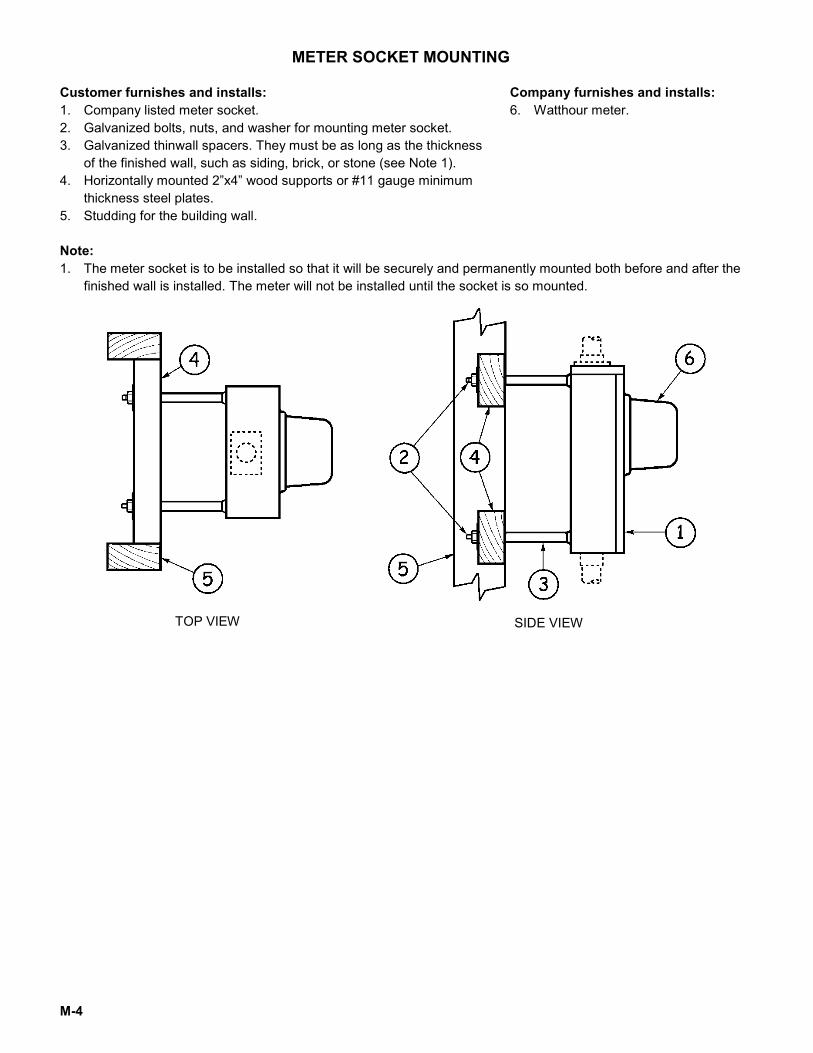
METER SOCKET MOUNTING
Customer furnishes and installs: 1. Company listed meter socket. 2. Galvanized bolts, nuts, and washer for mounting meter socket. 3. Galvanized thinwall spacers. They must be as long as the thickness
of the finished wall, such as siding, brick, or stone (see Note 1). 4. Horizontally mounted 2”x4” wood supports or #11 gauge minimum
thickness steel plates. 5. Studding for the building wall.
Company furnishes and installs: 6. Watthour meter.
Note: 1. The meter socket is to be installed so that it will be securely and permanently mounted both before and after the
finished wall is installed. The meter will not be installed until the socket is so mounted.
TOP VIEW SIDE VIEW
M-5
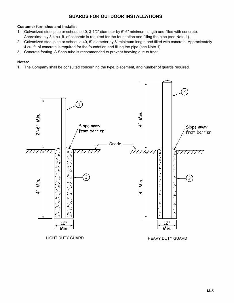
GUARDS FOR OUTDOOR INSTALLATIONS
Customer furnishes and installs: 1. Galvanized steel pipe or schedule 40, 3-1/2” diameter by 6’-6” minimum length and filled with concrete.
Approximately 3.4 cu. ft. of concrete is required for the foundation and filling the pipe (see Note 1). 2. Galvanized steel pipe or schedule 40, 6” diameter by 8’ minimum length and filled with concrete. Approximately
4 cu. ft. of concrete is required for the foundation and filling the pipe (see Note 1). 3. Concrete footing. A Sono tube is recommended to prevent heaving due to frost. Notes: 1. The Company shall be consulted concerning the type, placement, and number of guards required.
LIGHT DUTY GUARD HEAVY DUTY GUARD
M-6
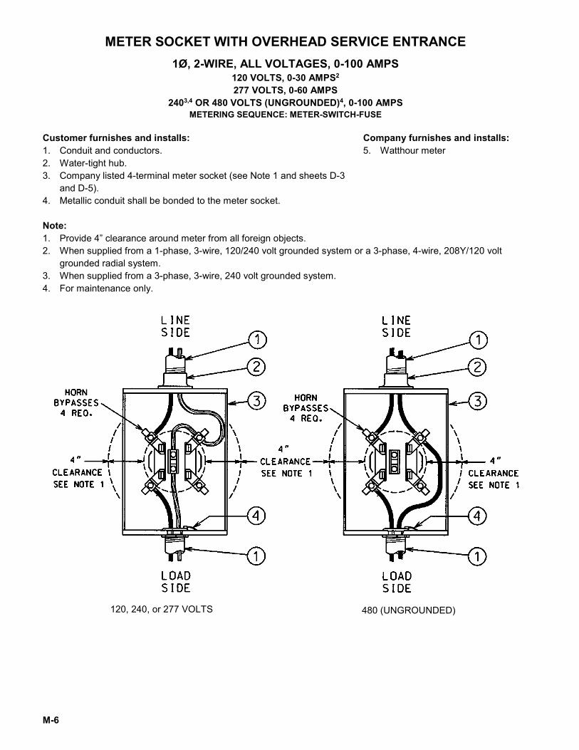
METER SOCKET WITH OVERHEAD SERVICE ENTRANCE 1Ø, 2-WIRE, ALL VOLTAGES, 0-100 AMPS
120 VOLTS, 0-30 AMPS2
277 VOLTS, 0-60 AMPS 2403,4 OR 480 VOLTS (UNGROUNDED)4, 0-100 AMPS
METERING SEQUENCE: METER-SWITCH-FUSE
Customer furnishes and installs: 1. Conduit and conductors. 2. Water-tight hub. 3. Company listed 4-terminal meter socket (see Note 1 and sheets D-3
and D-5). 4. Metallic conduit shall be bonded to the meter socket.
Company furnishes and installs: 5. Watthour meter
Note: 1. Provide 4” clearance around meter from all foreign objects. 2. When supplied from a 1-phase, 3-wire, 120/240 volt grounded system or a 3-phase, 4-wire, 208Y/120 volt
grounded radial system. 3. When supplied from a 3-phase, 3-wire, 240 volt grounded system. 4. For maintenance only.
120, 240, or 277 VOLTS 480 (UNGROUNDED)
M-7
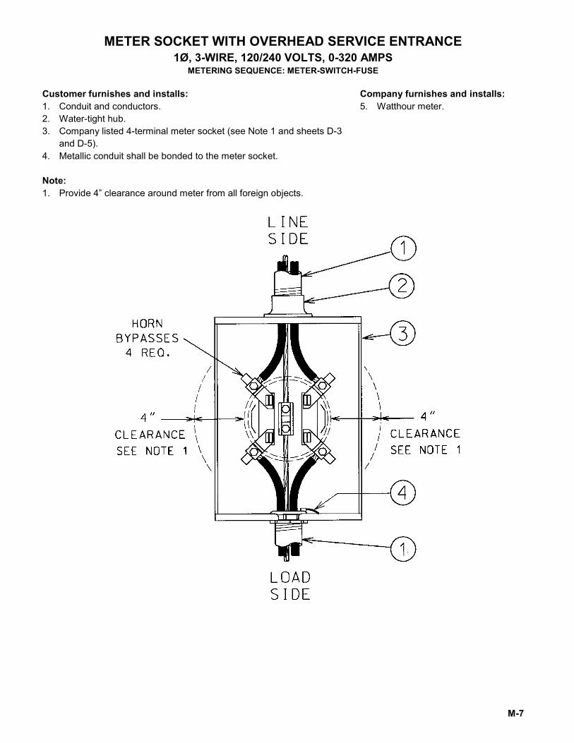
METER SOCKET WITH OVERHEAD SERVICE ENTRANCE 1Ø, 3-WIRE, 120/240 VOLTS, 0-320 AMPS
METERING SEQUENCE: METER-SWITCH-FUSE
Customer furnishes and installs: 1. Conduit and conductors. 2. Water-tight hub. 3. Company listed 4-terminal meter socket (see Note 1 and sheets D-3
and D-5). 4. Metallic conduit shall be bonded to the meter socket.
Company furnishes and installs: 5. Watthour meter.
Note: 1. Provide 4” clearance around meter from all foreign objects.
M-8
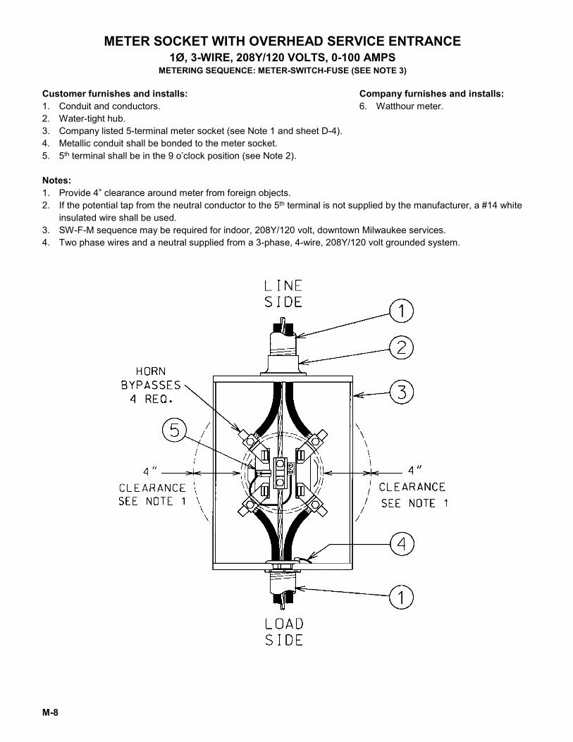
METER SOCKET WITH OVERHEAD SERVICE ENTRANCE 1Ø, 3-WIRE, 208Y/120 VOLTS, 0-100 AMPS
METERING SEQUENCE: METER-SWITCH-FUSE (SEE NOTE 3)
Customer furnishes and installs: 1. Conduit and conductors. 2. Water-tight hub. 3. Company listed 5-terminal meter socket (see Note 1 and sheet D-4). 4. Metallic conduit shall be bonded to the meter socket. 5. 5th terminal shall be in the 9 o’clock position (see Note 2).
Company furnishes and installs: 6. Watthour meter.
Notes: 1. Provide 4” clearance around meter from foreign objects. 2. If the potential tap from the neutral conductor to the 5th terminal is not supplied by the manufacturer, a #14 white
insulated wire shall be used. 3. SW-F-M sequence may be required for indoor, 208Y/120 volt, downtown Milwaukee services. 4. Two phase wires and a neutral supplied from a 3-phase, 4-wire, 208Y/120 volt grounded system.
M-9
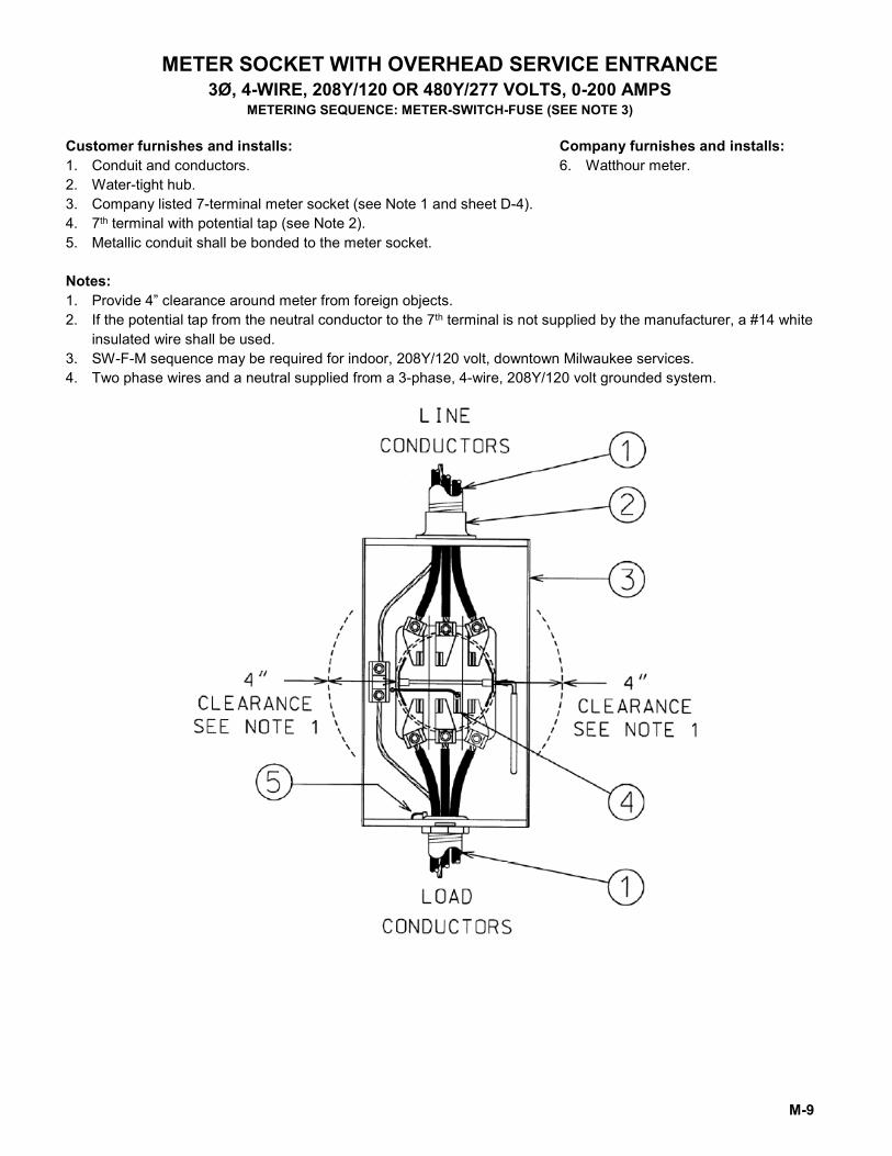
METER SOCKET WITH OVERHEAD SERVICE ENTRANCE 3Ø, 4-WIRE, 208Y/120 OR 480Y/277 VOLTS, 0-200 AMPS
METERING SEQUENCE: METER-SWITCH-FUSE (SEE NOTE 3)
Customer furnishes and installs: 1. Conduit and conductors. 2. Water-tight hub. 3. Company listed 7-terminal meter socket (see Note 1 and sheet D-4). 4. 7th terminal with potential tap (see Note 2). 5. Metallic conduit shall be bonded to the meter socket.
Company furnishes and installs: 6. Watthour meter.
Notes: 1. Provide 4” clearance around meter from foreign objects. 2. If the potential tap from the neutral conductor to the 7th terminal is not supplied by the manufacturer, a #14 white
insulated wire shall be used. 3. SW-F-M sequence may be required for indoor, 208Y/120 volt, downtown Milwaukee services. 4. Two phase wires and a neutral supplied from a 3-phase, 4-wire, 208Y/120 volt grounded system.
M-10
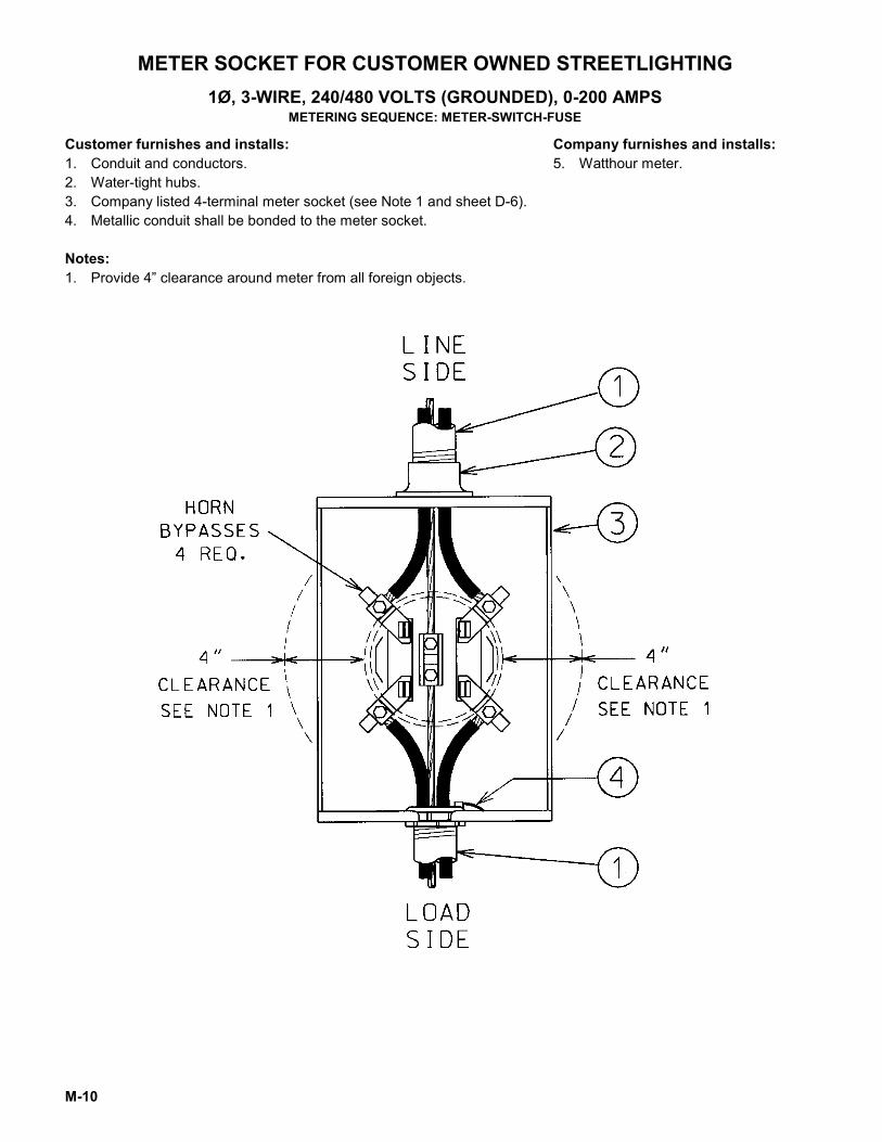
METER SOCKET FOR CUSTOMER OWNED STREETLIGHTING 1Ø, 3-WIRE, 240/480 VOLTS (GROUNDED), 0-200 AMPS
METERING SEQUENCE: METER-SWITCH-FUSE
Customer furnishes and installs: 1. Conduit and conductors. 2. Water-tight hubs. 3. Company listed 4-terminal meter socket (see Note 1 and sheet D-6). 4. Metallic conduit shall be bonded to the meter socket.
Company furnishes and installs: 5. Watthour meter.
Notes: 1. Provide 4” clearance around meter from all foreign objects.
M-11
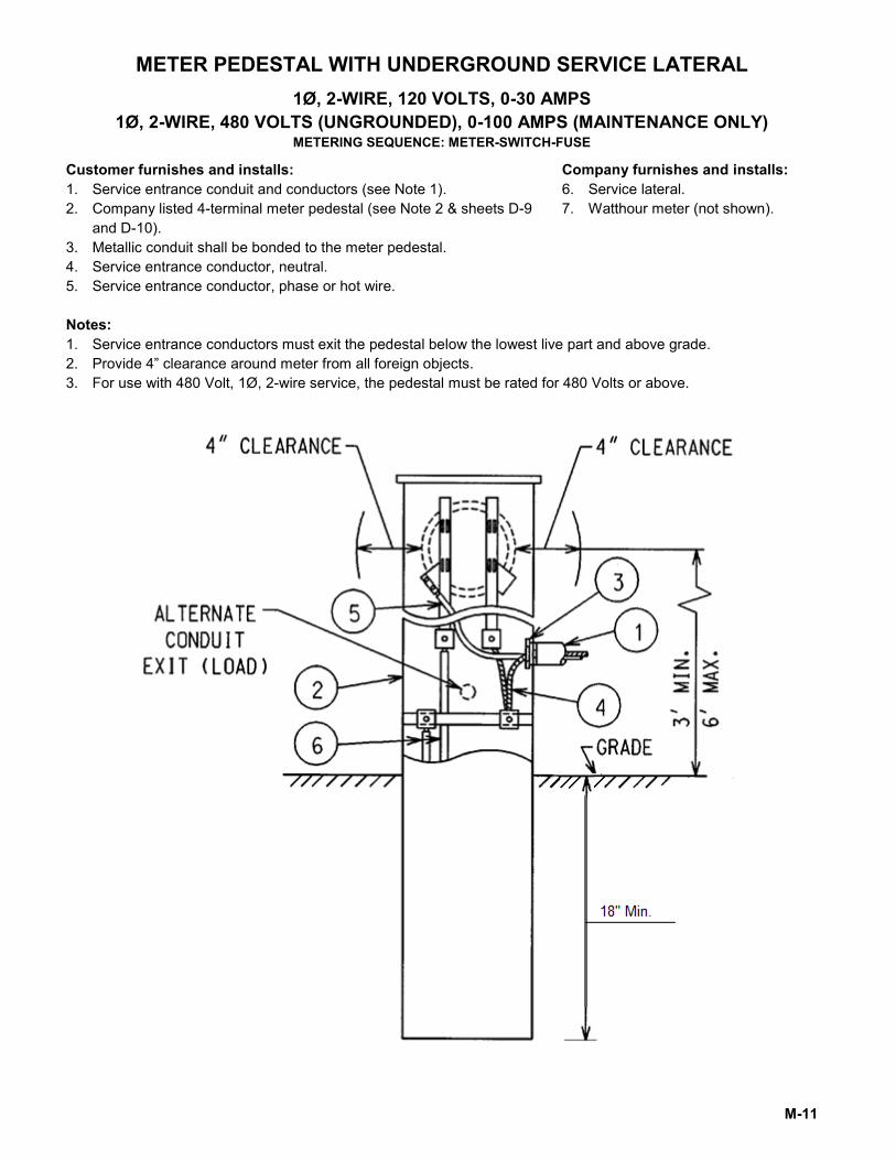
METER PEDESTAL WITH UNDERGROUND SERVICE LATERAL 1Ø, 2-WIRE, 120 VOLTS, 0-30 AMPS
1Ø, 2-WIRE, 480 VOLTS (UNGROUNDED), 0-100 AMPS (MAINTENANCE ONLY) METERING SEQUENCE: METER-SWITCH-FUSE
Customer furnishes and installs: 1. Service entrance conduit and conductors (see Note 1). 2. Company listed 4-terminal meter pedestal (see Note 2 & sheets D-9
and D-10). 3. Metallic conduit shall be bonded to the meter pedestal. 4. Service entrance conductor, neutral. 5. Service entrance conductor, phase or hot wire.
Company furnishes and installs: 6. Service lateral. 7. Watthour meter (not shown).
Notes: 1. Service entrance conductors must exit the pedestal below the lowest live part and above grade. 2. Provide 4” clearance around meter from all foreign objects. 3. For use with 480 Volt, 1Ø, 2-wire service, the pedestal must be rated for 480 Volts or above.
M-12
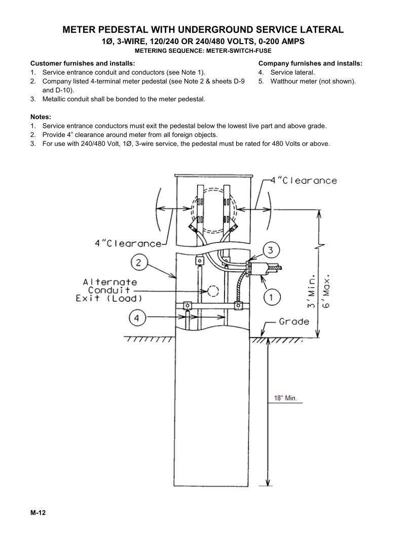
METER PEDESTAL WITH UNDERGROUND SERVICE LATERAL 1Ø, 3-WIRE, 120/240 OR 240/480 VOLTS, 0-200 AMPS
METERING SEQUENCE: METER-SWITCH-FUSE
Customer furnishes and installs: 1. Service entrance conduit and conductors (see Note 1). 2. Company listed 4-terminal meter pedestal (see Note 2 & sheets D-9
and D-10). 3. Metallic conduit shall be bonded to the meter pedestal.
Company furnishes and installs: 4. Service lateral. 5. Watthour meter (not shown).
Notes: 1. Service entrance conductors must exit the pedestal below the lowest live part and above grade. 2. Provide 4” clearance around meter from all foreign objects. 3. For use with 240/480 Volt, 1Ø, 3-wire service, the pedestal must be rated for 480 Volts or above.
M-13
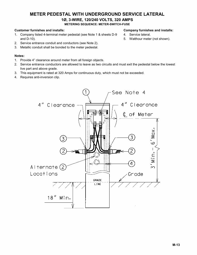
METER PEDESTAL WITH UNDERGROUND SERVICE LATERAL 1Ø, 3-WIRE, 120/240 VOLTS, 320 AMPS
METERING SEQUENCE: METER-SWITCH-FUSE
Customer furnishes and installs: 1. Company listed 4-terminal meter pedestal (see Note 1 & sheets D-9
and D-10). 2. Service entrance conduit and conductors (see Note 2). 3. Metallic conduit shall be bonded to the meter pedestal.
Company furnishes and installs: 4. Service lateral. 5. Watthour meter (not shown).
Notes: 1. Provide 4” clearance around meter from all foreign objects. 2. Service entrance conductors are allowed to leave as two circuits and must exit the pedestal below the lowest
live part and above grade. 3. This equipment is rated at 320 Amps for continuous duty, which must not be exceeded. 4. Requires anti-inversion clip.
M-14
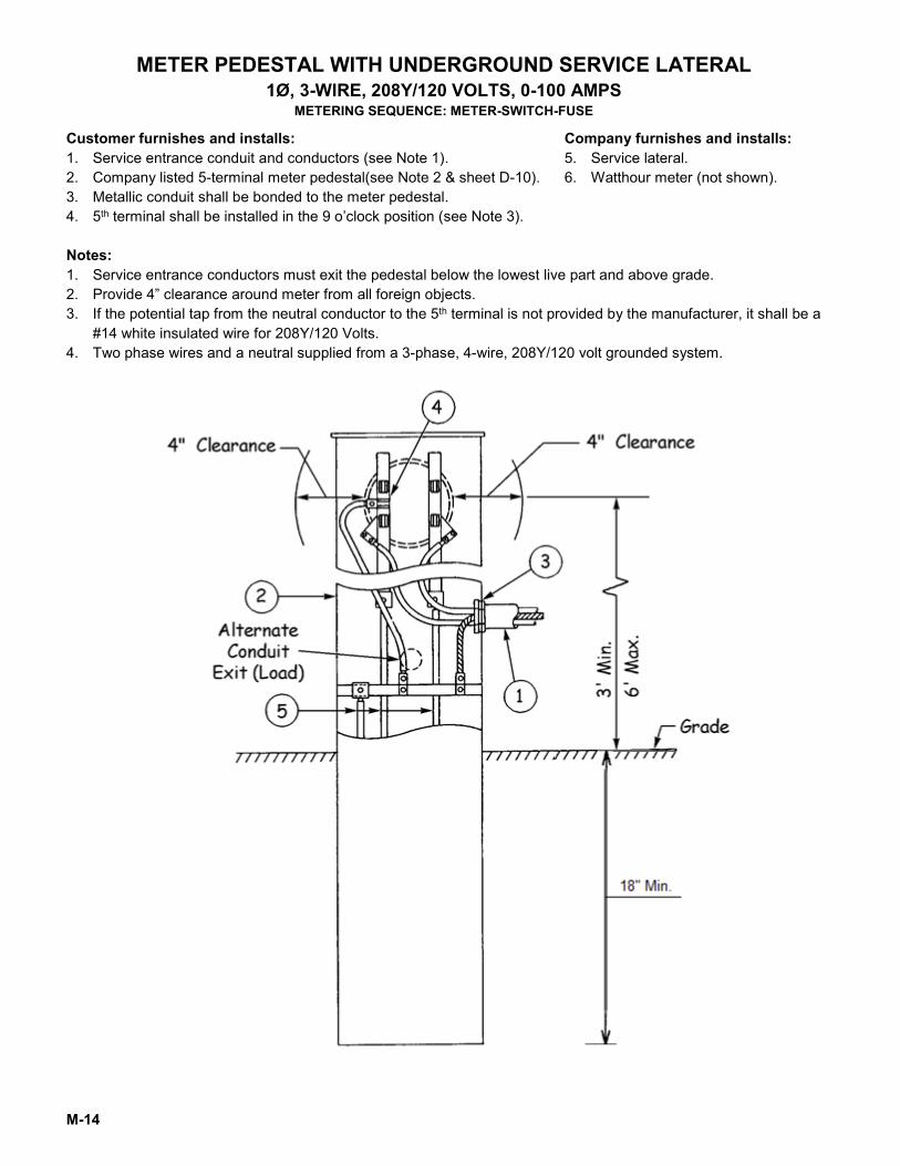
METER PEDESTAL WITH UNDERGROUND SERVICE LATERAL 1Ø, 3-WIRE, 208Y/120 VOLTS, 0-100 AMPS
METERING SEQUENCE: METER-SWITCH-FUSE
Customer furnishes and installs: 1. Service entrance conduit and conductors (see Note 1). 2. Company listed 5-terminal meter pedestal(see Note 2 & sheet D-10). 3. Metallic conduit shall be bonded to the meter pedestal. 4. 5th terminal shall be installed in the 9 o’clock position (see Note 3).
Company furnishes and installs: 5. Service lateral. 6. Watthour meter (not shown).
Notes: 1. Service entrance conductors must exit the pedestal below the lowest live part and above grade. 2. Provide 4” clearance around meter from all foreign objects. 3. If the potential tap from the neutral conductor to the 5th terminal is not provided by the manufacturer, it shall be a
#14 white insulated wire for 208Y/120 Volts. 4. Two phase wires and a neutral supplied from a 3-phase, 4-wire, 208Y/120 volt grounded system.
M-15
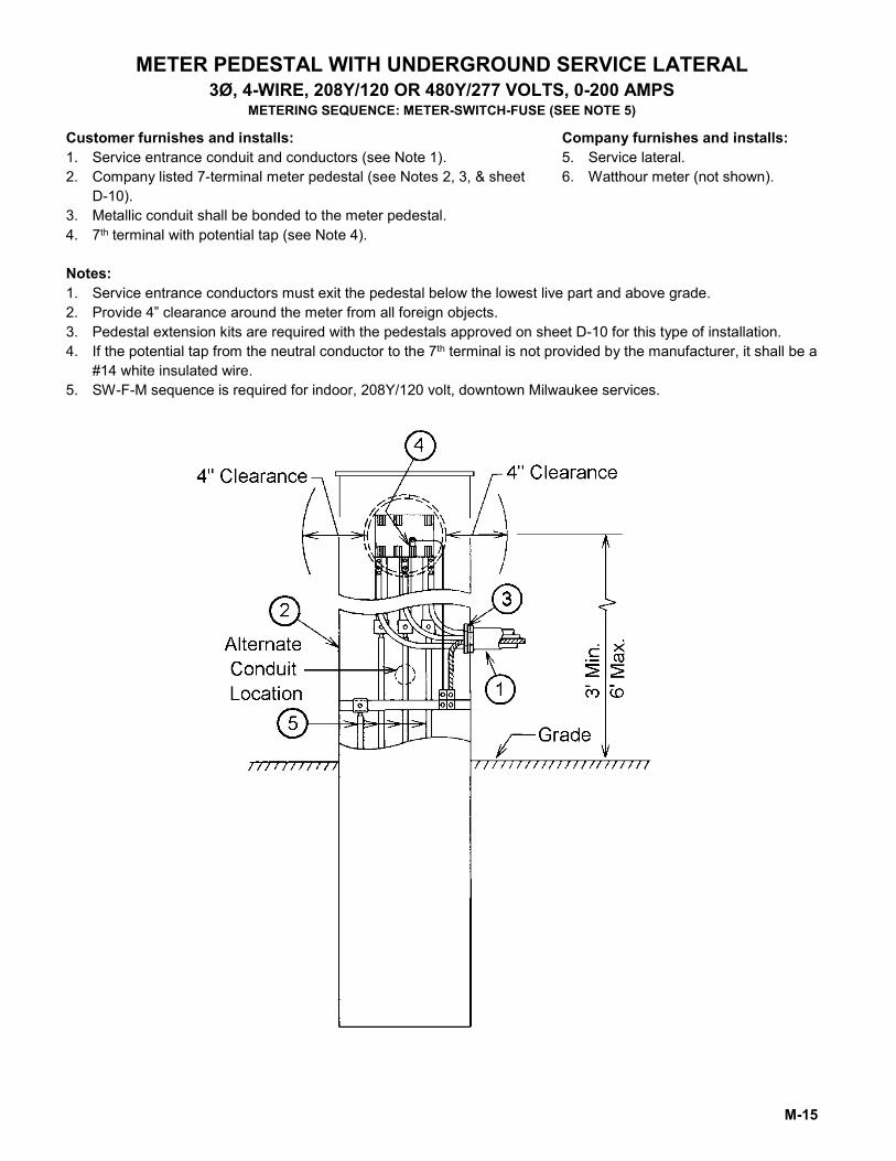
METER PEDESTAL WITH UNDERGROUND SERVICE LATERAL 3Ø, 4-WIRE, 208Y/120 OR 480Y/277 VOLTS, 0-200 AMPS
METERING SEQUENCE: METER-SWITCH-FUSE (SEE NOTE 5)
Customer furnishes and installs: 1. Service entrance conduit and conductors (see Note 1). 2. Company listed 7-terminal meter pedestal (see Notes 2, 3, & sheet
D-10). 3. Metallic conduit shall be bonded to the meter pedestal. 4. 7th terminal with potential tap (see Note 4).
Company furnishes and installs: 5. Service lateral. 6. Watthour meter (not shown).
Notes: 1. Service entrance conductors must exit the pedestal below the lowest live part and above grade. 2. Provide 4” clearance around the meter from all foreign objects. 3. Pedestal extension kits are required with the pedestals approved on sheet D-10 for this type of installation. 4. If the potential tap from the neutral conductor to the 7th terminal is not provided by the manufacturer, it shall be a
#14 white insulated wire. 5. SW-F-M sequence is required for indoor, 208Y/120 volt, downtown Milwaukee services.
M-16
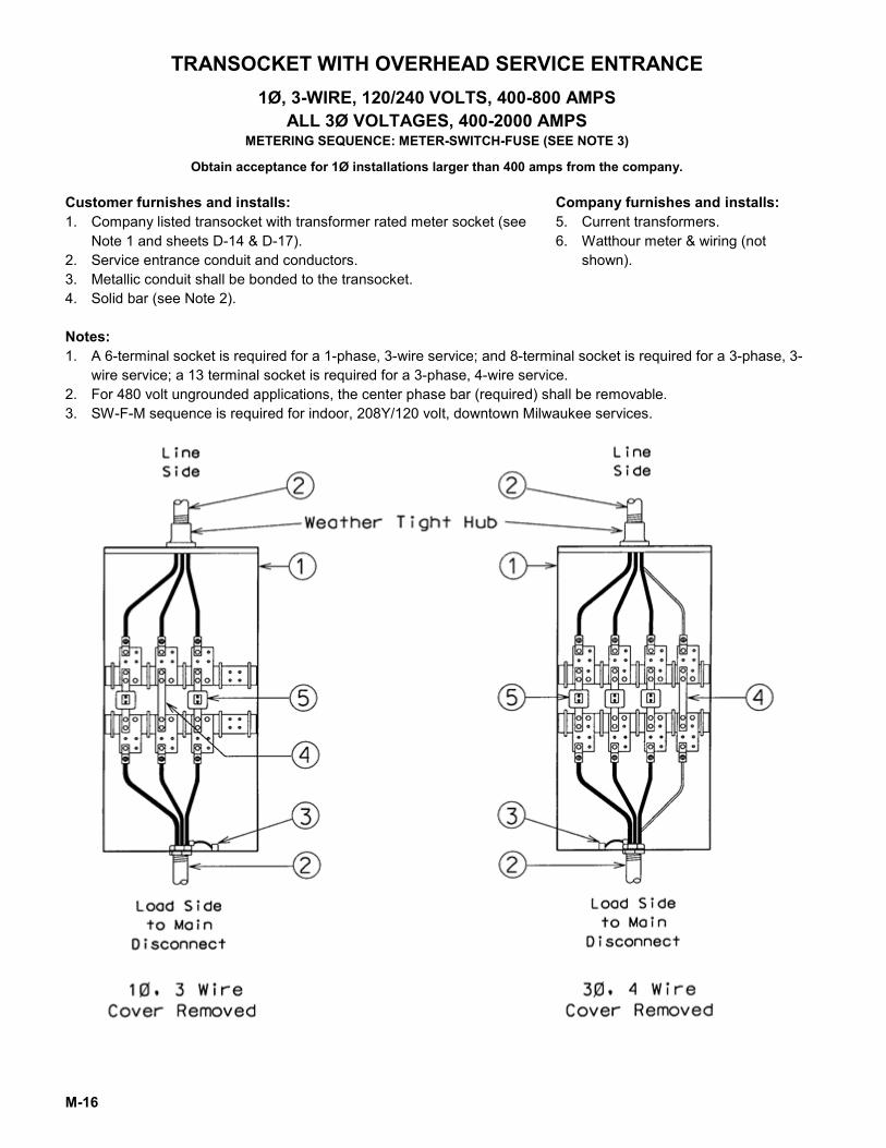
TRANSOCKET WITH OVERHEAD SERVICE ENTRANCE 1Ø, 3-WIRE, 120/240 VOLTS, 400-800 AMPS
ALL 3Ø VOLTAGES, 400-2000 AMPS METERING SEQUENCE: METER-SWITCH-FUSE (SEE NOTE 3)
Obtain acceptance for 1Ø installations larger than 400 amps from the company.
Customer furnishes and installs: 1. Company listed transocket with transformer rated meter socket (see
Note 1 and sheets D-14 & D-17). 2. Service entrance conduit and conductors. 3. Metallic conduit shall be bonded to the transocket. 4. Solid bar (see Note 2).
Company furnishes and installs: 5. Current transformers. 6. Watthour meter & wiring (not
shown).
Notes: 1. A 6-terminal socket is required for a 1-phase, 3-wire service; and 8-terminal socket is required for a 3-phase, 3-
wire service; a 13 terminal socket is required for a 3-phase, 4-wire service. 2. For 480 volt ungrounded applications, the center phase bar (required) shall be removable. 3. SW-F-M sequence is required for indoor, 208Y/120 volt, downtown Milwaukee services.
M-17
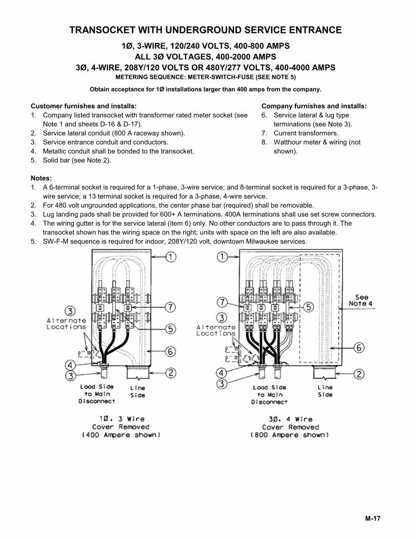
TRANSOCKET WITH UNDERGROUND SERVICE ENTRANCE 1Ø, 3-WIRE, 120/240 VOLTS, 400-800 AMPS
ALL 3Ø VOLTAGES, 400-2000 AMPS 3Ø, 4-WIRE, 208Y/120 VOLTS OR 480Y/277 VOLTS, 400-4000 AMPS
METERING SEQUENCE: METER-SWITCH-FUSE (SEE NOTE 5)
Obtain acceptance for 1Ø installations larger than 400 amps from the company.
Customer furnishes and installs: 1. Company listed transocket with transformer rated meter socket (see
Note 1 and sheets D-16 & D-17). 2. Service lateral conduit (800 A raceway shown). 3. Service entrance conduit and conductors. 4. Metallic conduit shall be bonded to the transocket. 5. Solid bar (see Note 2).
Company furnishes and installs: 6. Service lateral & lug type
terminations (see Note 3). 7. Current transformers. 8. Watthour meter & wiring (not
shown).
Notes: 1. A 6-terminal socket is required for a 1-phase, 3-wire service; and 8-terminal socket is required for a 3-phase, 3-
wire service; a 13 terminal socket is required for a 3-phase, 4-wire service. 2. For 480 volt ungrounded applications, the center phase bar (required) shall be removable. 3. Lug landing pads shall be provided for 600+ A terminations. 400A terminations shall use set screw connectors. 4. The wiring gutter is for the service lateral (item 6) only. No other conductors are to pass through it. The
transocket shown has the wiring space on the right; units with space on the left are also available. 5. SW-F-M sequence is required for indoor, 208Y/120 volt, downtown Milwaukee services.
M-18
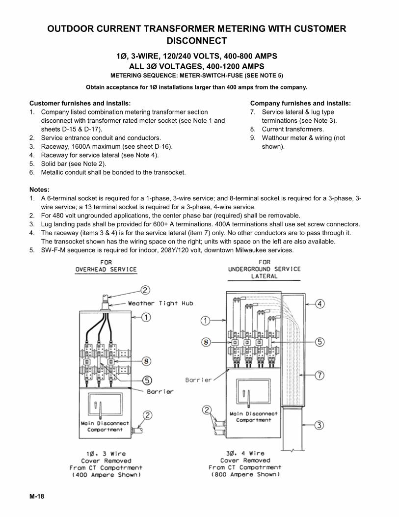
OUTDOOR CURRENT TRANSFORMER METERING WITH CUSTOMER DISCONNECT
1Ø, 3-WIRE, 120/240 VOLTS, 400-800 AMPS ALL 3Ø VOLTAGES, 400-1200 AMPS
METERING SEQUENCE: METER-SWITCH-FUSE (SEE NOTE 5)
Obtain acceptance for 1Ø installations larger than 400 amps from the company.
Customer furnishes and installs: 1. Company listed combination metering transformer section
disconnect with transformer rated meter socket (see Note 1 and sheets D-15 & D-17).
2. Service entrance conduit and conductors. 3. Raceway, 1600A maximum (see sheet D-16). 4. Raceway for service lateral (see Note 4). 5. Solid bar (see Note 2). 6. Metallic conduit shall be bonded to the transocket.
Company furnishes and installs: 7. Service lateral & lug type
terminations (see Note 3). 8. Current transformers. 9. Watthour meter & wiring (not
shown).
Notes: 1. A 6-terminal socket is required for a 1-phase, 3-wire service; and 8-terminal socket is required for a 3-phase, 3-
wire service; a 13 terminal socket is required for a 3-phase, 4-wire service. 2. For 480 volt ungrounded applications, the center phase bar (required) shall be removable. 3. Lug landing pads shall be provided for 600+ A terminations. 400A terminations shall use set screw connectors. 4. The raceway (items 3 & 4) is for the service lateral (item 7) only. No other conductors are to pass through it.
The transocket shown has the wiring space on the right; units with space on the left are also available. 5. SW-F-M sequence is required for indoor, 208Y/120 volt, downtown Milwaukee services.
M-19
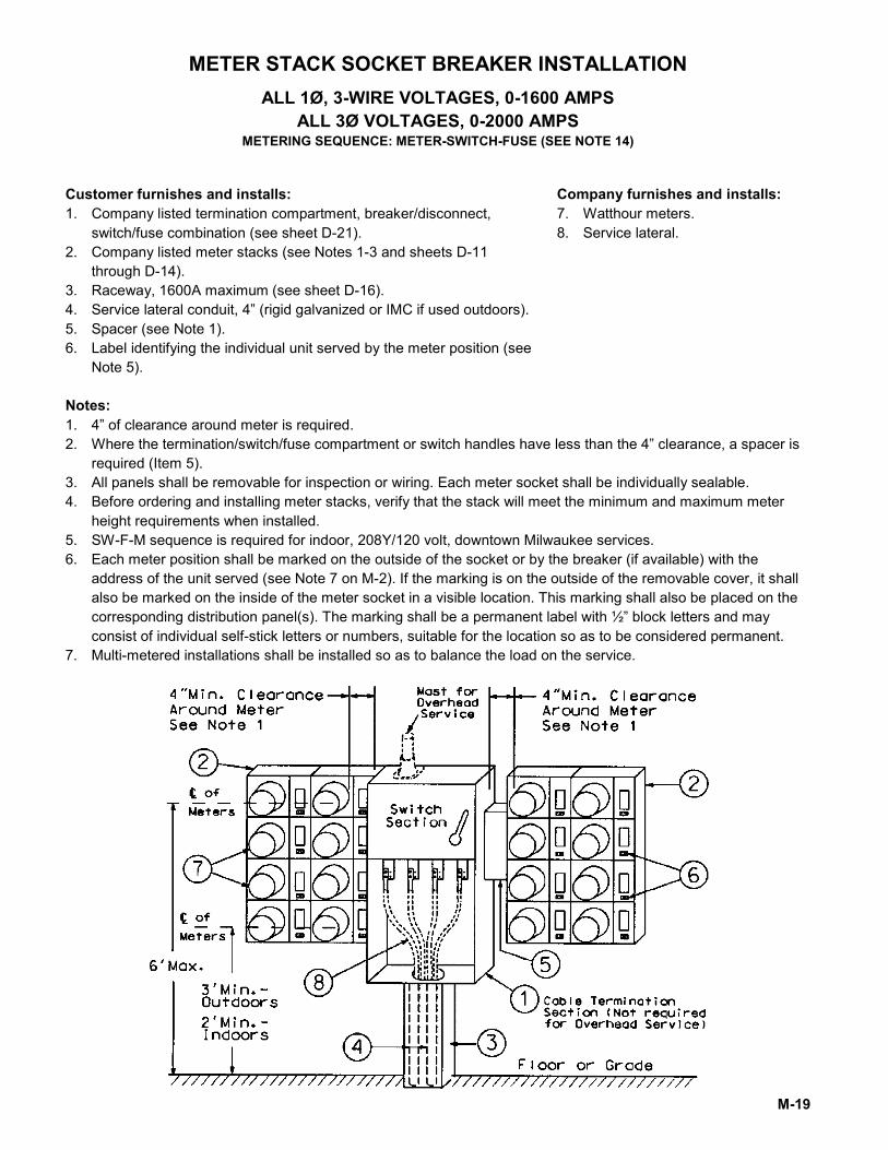
METER STACK SOCKET BREAKER INSTALLATION ALL 1Ø, 3-WIRE VOLTAGES, 0-1600 AMPS
ALL 3Ø VOLTAGES, 0-2000 AMPS METERING SEQUENCE: METER-SWITCH-FUSE (SEE NOTE 14)
Customer furnishes and installs: 1. Company listed termination compartment, breaker/disconnect,
switch/fuse combination (see sheet D-21). 2. Company listed meter stacks (see Notes 1-3 and sheets D-11
through D-14). 3. Raceway, 1600A maximum (see sheet D-16). 4. Service lateral conduit, 4” (rigid galvanized or IMC if used outdoors). 5. Spacer (see Note 1). 6. Label identifying the individual unit served by the meter position (see
Note 5).
Company furnishes and installs: 7. Watthour meters. 8. Service lateral.
Notes: 1. 4” of clearance around meter is required. 2. Where the termination/switch/fuse compartment or switch handles have less than the 4” clearance, a spacer is
required (Item 5). 3. All panels shall be removable for inspection or wiring. Each meter socket shall be individually sealable. 4. Before ordering and installing meter stacks, verify that the stack will meet the minimum and maximum meter
height requirements when installed. 5. SW-F-M sequence is required for indoor, 208Y/120 volt, downtown Milwaukee services. 6. Each meter position shall be marked on the outside of the socket or by the breaker (if available) with the
address of the unit served (see Note 7 on M-2). If the marking is on the outside of the removable cover, it shall also be marked on the inside of the meter socket in a visible location. This marking shall also be placed on the corresponding distribution panel(s). The marking shall be a permanent label with ½” block letters and may consist of individual self-stick letters or numbers, suitable for the location so as to be considered permanent.
7. Multi-metered installations shall be installed so as to balance the load on the service.
M-20
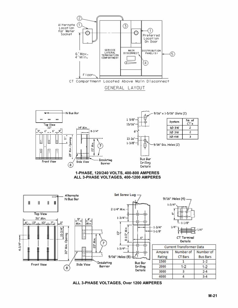
CURRENT TRANSFORMER METERING IN FREE STANDING SWITCHGEAR 1Ø, 3-WIRE, 120/240 VOLTS, 400-800 AMPS
ALL 3Ø VOLTAGES, 400-4000 AMPS METERING SEQUENCE: METER-SWITCH-FUSE (SEE NOTE 14)
Customer furnishes and installs: 1. Company listed transformer rated meter socket (see Note 1 and
Sheet D-17). 2. Conduit (see Note 2). 3. Current transformer (CT) compartment as part of the main
switchboard (see Notes 3 to 12). 4. Main breaker compartment. 5. Distribution equipment. 6. Service entrances (see Overhead or Underground sections for
installation details). 7. Alternate location of the line and load side bus bar. 8. Alternate location for insulating barrier when alternate load bus is
used.
Company furnishes and installs: 9. Meter test switch (not shown). 10. Watthour meter (not shown). 11. Meter wire from the secondary side
of CTs to meter (not shown). 12. CTs and necessary mounting bolts
(not shown).
Notes: 1. Meter socket shall be installed within sight of or attached to the CT compartment with the following limitations:
a. Meter must be installed in a suitable location as outlined in the preceding General Requirements. b. Meter conduit shall be run exposed where practicable. c. Consult the company if the distance between the CT compartment and meter location exceeds 40’.
2. 1-1/4” galvanized rigid, galvanized intermediate, or, if indoors, rigid nonmetallic Schedule 40 PVC per NEMA Standard TC-2, to extend between the CT compartment and meter cabinet. If nonmetallic conduit is used, a #12 copper conductor or equivalent must be installed in the conduit to maintain continuity of equipment ground. This conductor must be bare or green covered with one or more yellow stripes.
3. The CT compartment shall be completely enclosed; barriers between compartments shall be rigidly supported. 4. No transition bus is allowed within the CT compartment with the bus configuration shown. 5. Front of CT compartment shall be enclosed using one of the following methods:
a. Double hinged door with sealable hasp and double bolt type latch (preferred). b. Single hinged door with sealable hasp and double bolt type latch.
6. The following live part clearances must be maintained: 2” phase-to-phase, 1” phase-to-ground. 7. The CT bar will be drilled to conform to EEI Pub. MSJ-11. 8. For 1-phase and 3-phase services 1200 amps or less, provide a set screw lug for a #12 gauge wire in the
neutral bar for a potential tap. For 3-phase services over 1200 amps, provide a set screw lug for a #12 gauge wire in the bus bars of each phase and the neutral for the potential tap as shown in the bus bar drilling detail.
9. Bus supports shall have a minimum separation of 15” and shall consist of an insulating material such as Benelex. or equivalent, or porcelain insulators mounted on a steel channel.
10. Neutral bus must either run through or be extended back into the CT cabinet so that it is accessible for the potential tap. Working clearance between neutral bus and any live bus in the vicinity of the CT mounting must be 6” minimum. Neutral bus must not be located closer to the front of the enclosure than any live bus.
11. The compartment detail shown is for use with a 3-phase, 4-wire system. For 3-wire systems, the center phase bar is to be continuous and the neutral bar is to be omitted.
12. For services less than 1200 amps, refer to Sheet D-17 for approved CT compartments. 13. Send a copy of drawings of the switchgear termination and metering compartments to the local We
Energies job representative for acceptance prior to any construction. 14. SW-F-M sequence is required for indoor, 208Y/120 volt, downtown Milwaukee services.
M-21
1-PHASE, 120/240 VOLTS, 400-800 AMPERES ALL 3-PHASE VOLTAGES, 400-1200 AMPERES
ALL 3-PHASE VOLTAGES, Over 1200 AMPERES
M-22
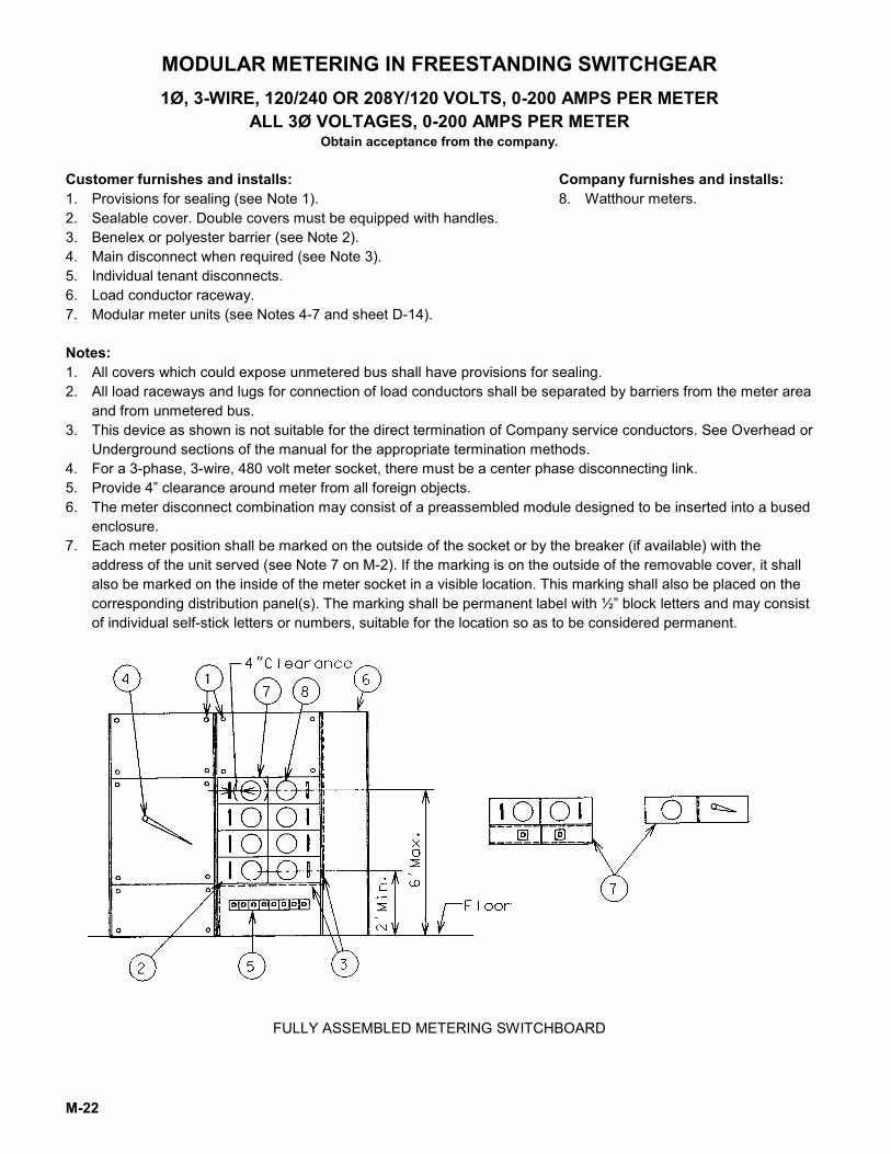
MODULAR METERING IN FREESTANDING SWITCHGEAR 1Ø, 3-WIRE, 120/240 OR 208Y/120 VOLTS, 0-200 AMPS PER METER
ALL 3Ø VOLTAGES, 0-200 AMPS PER METER Obtain acceptance from the company.
Customer furnishes and installs: 1. Provisions for sealing (see Note 1). 2. Sealable cover. Double covers must be equipped with handles. 3. Benelex or polyester barrier (see Note 2). 4. Main disconnect when required (see Note 3). 5. Individual tenant disconnects. 6. Load conductor raceway. 7. Modular meter units (see Notes 4-7 and sheet D-14).
Company furnishes and installs: 8. Watthour meters.
Notes: 1. All covers which could expose unmetered bus shall have provisions for sealing. 2. All load raceways and lugs for connection of load conductors shall be separated by barriers from the meter area
and from unmetered bus. 3. This device as shown is not suitable for the direct termination of Company service conductors. See Overhead or
Underground sections of the manual for the appropriate termination methods. 4. For a 3-phase, 3-wire, 480 volt meter socket, there must be a center phase disconnecting link. 5. Provide 4” clearance around meter from all foreign objects. 6. The meter disconnect combination may consist of a preassembled module designed to be inserted into a bused
enclosure. 7. Each meter position shall be marked on the outside of the socket or by the breaker (if available) with the
address of the unit served (see Note 7 on M-2). If the marking is on the outside of the removable cover, it shall also be marked on the inside of the meter socket in a visible location. This marking shall also be placed on the corresponding distribution panel(s). The marking shall be permanent label with ½” block letters and may consist of individual self-stick letters or numbers, suitable for the location so as to be considered permanent.
FULLY ASSEMBLED METERING SWITCHBOARD
M-23
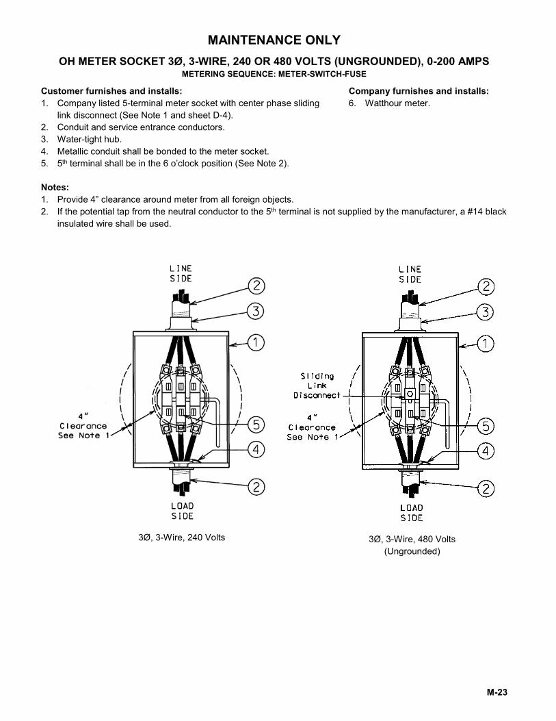
MAINTENANCE ONLY OH METER SOCKET 3Ø, 3-WIRE, 240 OR 480 VOLTS (UNGROUNDED), 0-200 AMPS
METERING SEQUENCE: METER-SWITCH-FUSE
Customer furnishes and installs: 1. Company listed 5-terminal meter socket with center phase sliding
link disconnect (See Note 1 and sheet D-4). 2. Conduit and service entrance conductors. 3. Water-tight hub. 4. Metallic conduit shall be bonded to the meter socket. 5. 5th terminal shall be in the 6 o’clock position (See Note 2).
Company furnishes and installs: 6. Watthour meter.
Notes: 1. Provide 4” clearance around meter from all foreign objects. 2. If the potential tap from the neutral conductor to the 5th terminal is not supplied by the manufacturer, a #14 black
insulated wire shall be used.
3Ø, 3-Wire, 240 Volts 3Ø, 3-Wire, 480 Volts (Ungrounded)
M-24
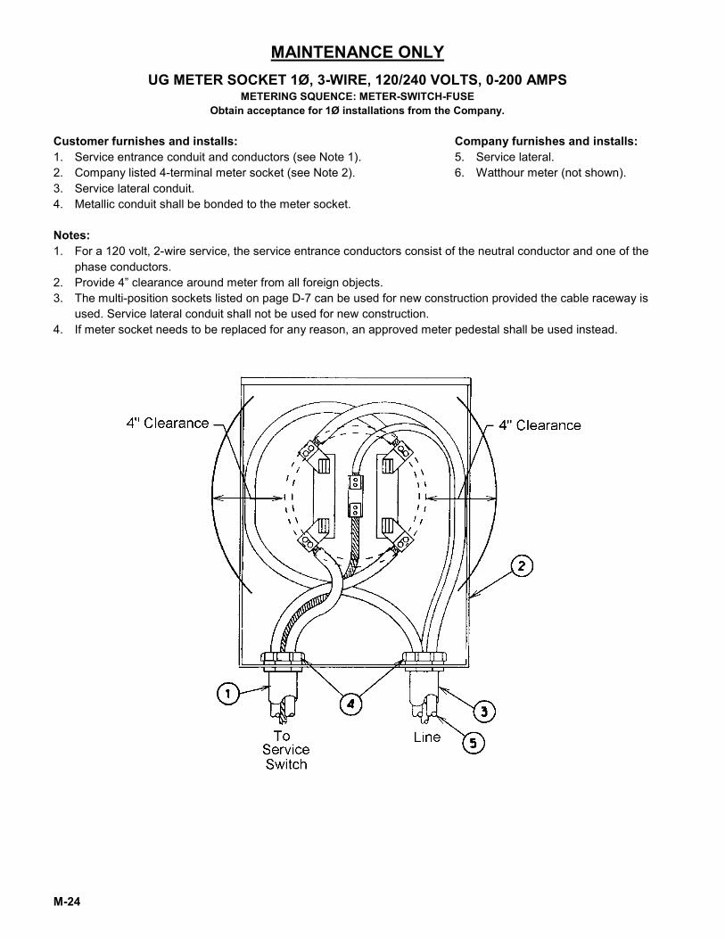
MAINTENANCE ONLY UG METER SOCKET 1Ø, 3-WIRE, 120/240 VOLTS, 0-200 AMPS
METERING SQUENCE: METER-SWITCH-FUSE Obtain acceptance for 1Ø installations from the Company.
Customer furnishes and installs: 1. Service entrance conduit and conductors (see Note 1). 2. Company listed 4-terminal meter socket (see Note 2). 3. Service lateral conduit. 4. Metallic conduit shall be bonded to the meter socket.
Company furnishes and installs: 5. Service lateral. 6. Watthour meter (not shown).
Notes: 1. For a 120 volt, 2-wire service, the service entrance conductors consist of the neutral conductor and one of the
phase conductors. 2. Provide 4” clearance around meter from all foreign objects. 3. The multi-position sockets listed on page D-7 can be used for new construction provided the cable raceway is
used. Service lateral conduit shall not be used for new construction. 4. If meter socket needs to be replaced for any reason, an approved meter pedestal shall be used instead.
M-25
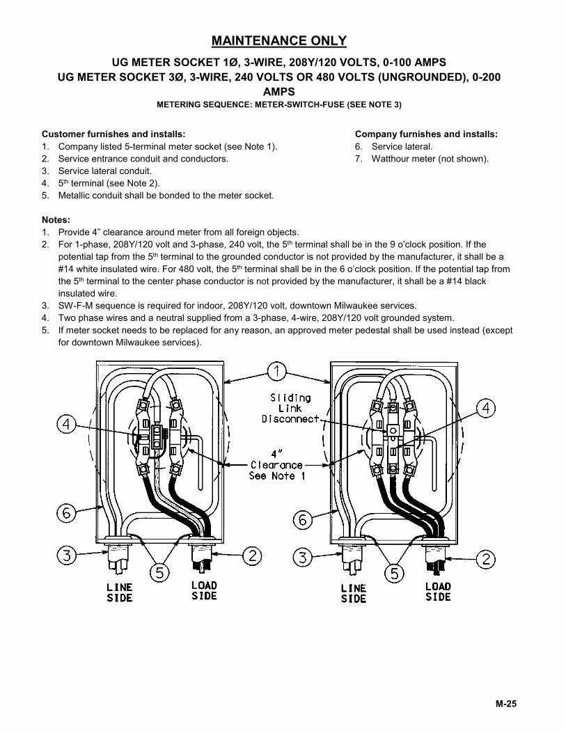
MAINTENANCE ONLY UG METER SOCKET 1Ø, 3-WIRE, 208Y/120 VOLTS, 0-100 AMPS
UG METER SOCKET 3Ø, 3-WIRE, 240 VOLTS OR 480 VOLTS (UNGROUNDED), 0-200 AMPS
METERING SEQUENCE: METER-SWITCH-FUSE (SEE NOTE 3)
Customer furnishes and installs: 1. Company listed 5-terminal meter socket (see Note 1). 2. Service entrance conduit and conductors. 3. Service lateral conduit. 4. 5th terminal (see Note 2). 5. Metallic conduit shall be bonded to the meter socket.
Company furnishes and installs: 6. Service lateral. 7. Watthour meter (not shown).
Notes: 1. Provide 4” clearance around meter from all foreign objects. 2. For 1-phase, 208Y/120 volt and 3-phase, 240 volt, the 5th terminal shall be in the 9 o’clock position. If the
potential tap from the 5th terminal to the grounded conductor is not provided by the manufacturer, it shall be a #14 white insulated wire. For 480 volt, the 5th terminal shall be in the 6 o’clock position. If the potential tap from the 5th terminal to the center phase conductor is not provided by the manufacturer, it shall be a #14 black insulated wire.
3. SW-F-M sequence is required for indoor, 208Y/120 volt, downtown Milwaukee services. 4. Two phase wires and a neutral supplied from a 3-phase, 4-wire, 208Y/120 volt grounded system. 5. If meter socket needs to be replaced for any reason, an approved meter pedestal shall be used instead (except
for downtown Milwaukee services).
M-26
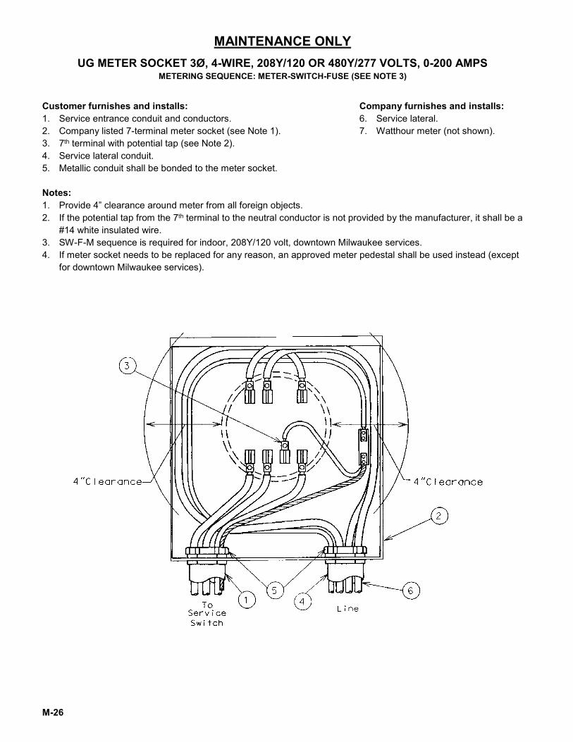
MAINTENANCE ONLY UG METER SOCKET 3Ø, 4-WIRE, 208Y/120 OR 480Y/277 VOLTS, 0-200 AMPS
METERING SEQUENCE: METER-SWITCH-FUSE (SEE NOTE 3)
Customer furnishes and installs: 1. Service entrance conduit and conductors. 2. Company listed 7-terminal meter socket (see Note 1). 3. 7th terminal with potential tap (see Note 2). 4. Service lateral conduit. 5. Metallic conduit shall be bonded to the meter socket.
Company furnishes and installs: 6. Service lateral. 7. Watthour meter (not shown).
Notes: 1. Provide 4” clearance around meter from all foreign objects. 2. If the potential tap from the 7th terminal to the neutral conductor is not provided by the manufacturer, it shall be a
#14 white insulated wire. 3. SW-F-M sequence is required for indoor, 208Y/120 volt, downtown Milwaukee services. 4. If meter socket needs to be replaced for any reason, an approved meter pedestal shall be used instead (except
for downtown Milwaukee services).
M-27
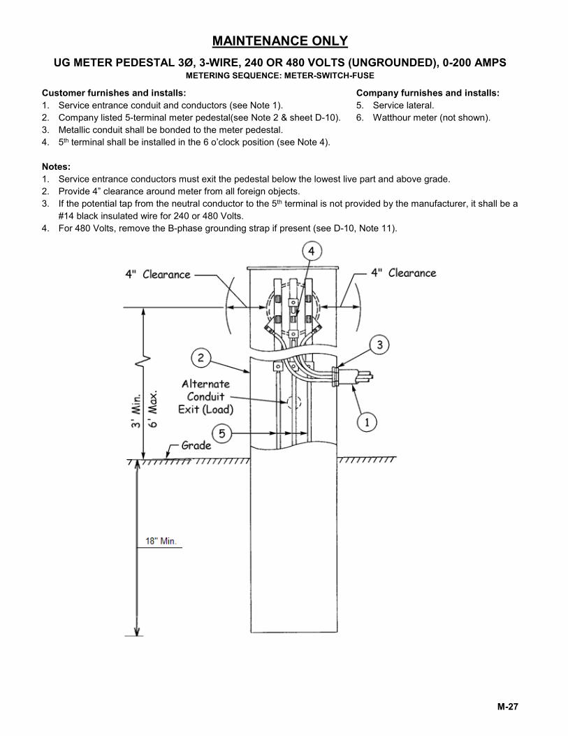
MAINTENANCE ONLY UG METER PEDESTAL 3Ø, 3-WIRE, 240 OR 480 VOLTS (UNGROUNDED), 0-200 AMPS
METERING SEQUENCE: METER-SWITCH-FUSE
Customer furnishes and installs: 1. Service entrance conduit and conductors (see Note 1). 2. Company listed 5-terminal meter pedestal(see Note 2 & sheet D-10). 3. Metallic conduit shall be bonded to the meter pedestal. 4. 5th terminal shall be installed in the 6 o’clock position (see Note 4).
Company furnishes and installs: 5. Service lateral. 6. Watthour meter (not shown).
Notes: 1. Service entrance conductors must exit the pedestal below the lowest live part and above grade. 2. Provide 4” clearance around meter from all foreign objects. 3. If the potential tap from the neutral conductor to the 5th terminal is not provided by the manufacturer, it shall be a
#14 black insulated wire for 240 or 480 Volts. 4. For 480 Volts, remove the B-phase grounding strap if present (see D-10, Note 11).
- i -
APPENDIX CHOOSING THE PROPER METER SOCKET
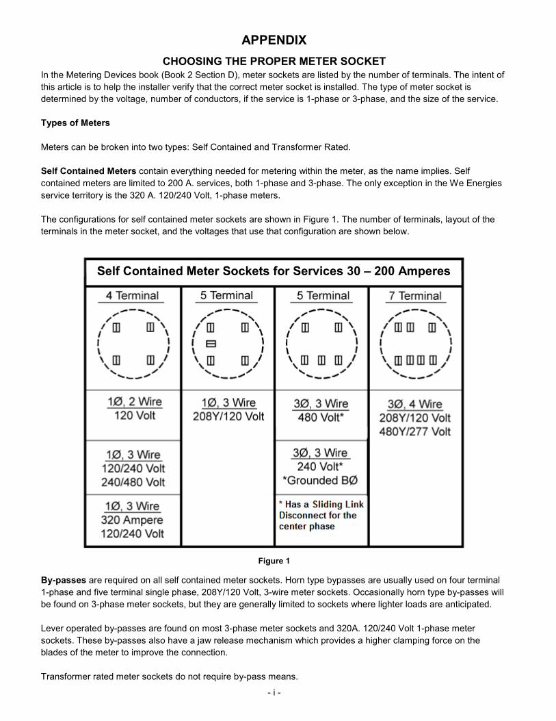
In the Metering Devices book (Book 2 Section D), meter sockets are listed by the number of terminals. The intent of this article is to help the installer verify that the correct meter socket is installed. The type of meter socket is determined by the voltage, number of conductors, if the service is 1-phase or 3-phase, and the size of the service. Types of Meters Meters can be broken into two types: Self Contained and Transformer Rated. Self Contained Meters contain everything needed for metering within the meter, as the name implies. Self contained meters are limited to 200 A. services, both 1-phase and 3-phase. The only exception in the We Energies service territory is the 320 A. 120/240 Volt, 1-phase meters. The configurations for self contained meter sockets are shown in Figure 1. The number of terminals, layout of the terminals in the meter socket, and the voltages that use that configuration are shown below.
Figure 1
By-passes are required on all self contained meter sockets. Horn type bypasses are usually used on four terminal 1-phase and five terminal single phase, 208Y/120 Volt, 3-wire meter sockets. Occasionally horn type by-passes will be found on 3-phase meter sockets, but they are generally limited to sockets where lighter loads are anticipated. Lever operated by-passes are found on most 3-phase meter sockets and 320A. 120/240 Volt 1-phase meter sockets. These by-passes also have a jaw release mechanism which provides a higher clamping force on the blades of the meter to improve the connection. Transformer rated meter sockets do not require by-pass means.
Self Contained Meter Sockets for Services 30 – 200 Amperes
- ii -
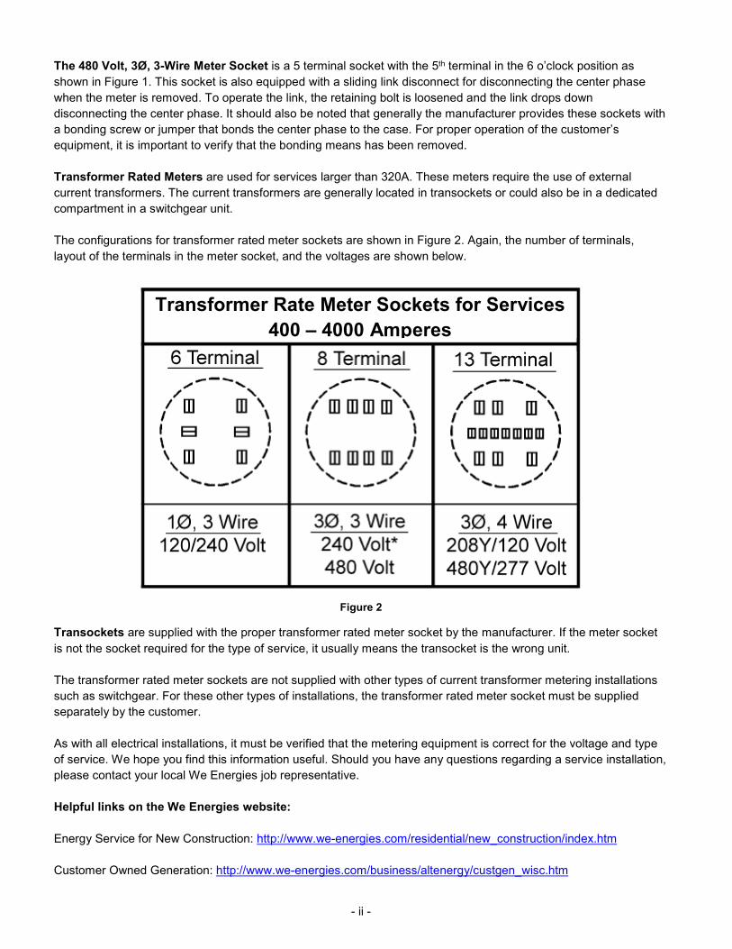
The 480 Volt, 3Ø, 3-Wire Meter Socket is a 5 terminal socket with the 5th terminal in the 6 o’clock position as shown in Figure 1. This socket is also equipped with a sliding link disconnect for disconnecting the center phase when the meter is removed. To operate the link, the retaining bolt is loosened and the link drops down disconnecting the center phase. It should also be noted that generally the manufacturer provides these sockets with a bonding screw or jumper that bonds the center phase to the case. For proper operation of the customer’s equipment, it is important to verify that the bonding means has been removed. Transformer Rated Meters are used for services larger than 320A. These meters require the use of external current transformers. The current transformers are generally located in transockets or could also be in a dedicated compartment in a switchgear unit. The configurations for transformer rated meter sockets are shown in Figure 2. Again, the number of terminals, layout of the terminals in the meter socket, and the voltages are shown below.
Figure 2
Transockets are supplied with the proper transformer rated meter socket by the manufacturer. If the meter socket is not the socket required for the type of service, it usually means the transocket is the wrong unit. The transformer rated meter sockets are not supplied with other types of current transformer metering installations such as switchgear. For these other types of installations, the transformer rated meter socket must be supplied separately by the customer. As with all electrical installations, it must be verified that the metering equipment is correct for the voltage and type of service. We hope you find this information useful. Should you have any questions regarding a service installation, please contact your local We Energies job representative. Helpful links on the We Energies website: Energy Service for New Construction: http://www.we-energies.com/residential/new_construction/index.htm Customer Owned Generation: http://www.we-energies.com/business/altenergy/custgen_wisc.htm
Transformer Rate Meter Sockets for Services 400 – 4000 Amperes
- iii -
APPENDIX RESIDENTIAL DECK PROCEDURE
1. When building a deck, service entrance equipment must remain accessible at all times. This procedure is on how to deal with problems once decks are built around meters.
2. Avoid installing the deck around the service entrance equipment. If a deck is built over a service lateral and a fault on the service lateral occurs, outage times may be long and costly to repair. The Company must be able to safely work on its equipment. The National Electric Code, NEC, Article 110 Requirements for Electrical Installations requires the follow working space clearances be met.
a. 110.26(A)(1) Depth of Working Space: A 3 ft. minimum from the front or opening of the enclosure containing live parts shall remain clear.
b. 110.26(A)(2) Width of Working Space: Width of working space in front of electrical equipment shall be the width of the equipment or 30 in., whichever is greater.
c. 110.26(A)(3) Height of Working Space: The work space shall be clear and extend from the grade to 6½ ft.
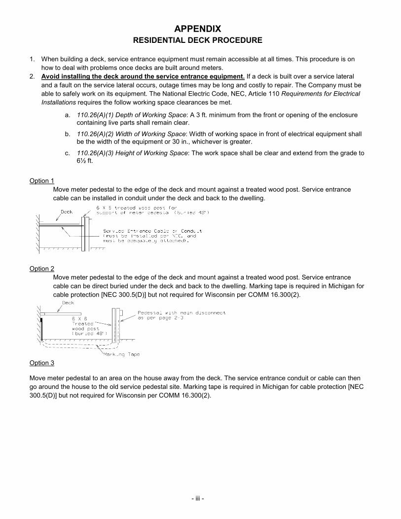
Option 1
Move meter pedestal to the edge of the deck and mount against a treated wood post. Service entrance cable can be installed in conduit under the deck and back to the dwelling.
Option 2
Move meter pedestal to the edge of the deck and mount against a treated wood post. Service entrance cable can be direct buried under the deck and back to the dwelling. Marking tape is required in Michigan for cable protection [NEC 300.5(D)] but not required for Wisconsin per COMM 16.300(2).
Option 3
Move meter pedestal to an area on the house away from the deck. The service entrance conduit or cable can then go around the house to the old service pedestal site. Marking tape is required in Michigan for cable protection [NEC 300.5(D)] but not required for Wisconsin per COMM 16.300(2).
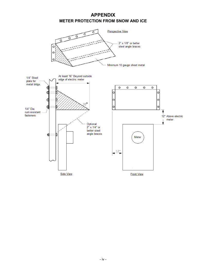
- iv -
APPENDIX METER PROTECTION FROM SNOW AND ICE