Embed Size (px)
Citation preview
Bureau of Mines Report of Investigations/l985
Methane Control on Longwalls With Cross- Measure Boreholes (Lower Kittanning Coalbed)
By F. Garcia and J. Cervik
UNITED STATES DEPARTMENT OF THE INTERIOR C
MINES 75TH A ~ $
Report of Investigations 8985
Methane Control on Longwalls With Cross- Measure Boreholes (Lower Kittanning Coal bed)
By F. Garcia and J. Cervik
UNITED STATES DEPARTMENT OF THE INTERIOR Donald Paul Hodel, Secretary
BUREAU OF MINES Robert C. Horton, Director
Library of Congress Cataloging in Publ icat ion Data :
Garcia, F, (Fred) M e t h a n e con t ro l on l o n g w a l l s w i th c r o s s - m e a s u r e b o r e h o l e s ( L o w e r
K i t t a n n i n g C o a l b e d ) .
( B u r e a u of M i n e s r e p o r t o f i n v e s t i g a t i o n s ; 8 9 8 5 )
B i b l i o g r a p h y : p. 17.
Sup t . o f D o c s . no.: I 28.23: 8985 .
1. C o a l b e d m e t h a n e d ra inage -Pennsy lvan ia -Cambr ia C o u n t y . 2. L o n g w a l l m in ing -Penn s y 1 v a n i a - C a m b r i a C o u n t y - S a f e t y m e a s u r e s . 3. Bo r ing . I. C e r v i k , J o s e p h . 11. T i t l e . 111. S e r i e s : R e p o r t of i n v e s - t i g a t i o n s ( U n i t e d S t a t e s . B u r e a u of M i n e s ) ; 8985 .
TN 23,U43 [TN 3051 622s [622'.334] 85-600 126

CONTENTS Page .
A b s t r a c t ....................................................................... I n t r o d u c t i o n ................................................................... Acknowledgments ................................................................ Study a r e a ..................................................................... D r i l l i n g equipment and p rocedures ...............................m.............. Methane removal sys tem ......................................................... .................................................. Cross-measure boreho le d e s i g n S u r f a c e gob h o l e s .............................................................. Underground and s u r f a c e i n s t r u m e n t a t i o n ........................................ Gas-water s e p a r a t o r sys tem ..................................................... Data a n a l y s e s ..................................................................
Longwall p roduc t ion .......................................................... ........................................ Cross-measure boreho le g a s p r o d u c t i o n ............................................... Methane m i g r a t i o n through gobs Borehole s p a c i n g ............................................................. Methane f low i n t h e r e t u r n a i r ............................................... Water p r o d u c t i o n ......................e....................................e. S u r f a c e gob h o l e p roduc t ion ..................................m...............
Migra t ion of g a s i n t o a boreho le ............................................... Summary and c o n c l u s i o n s ...................................m.................... References .....................................................................
ILLUSTRATIONS
....................... S t r a t i g r a p h i c column above Lower K i t t a n n i n g Coalbed BethEnergy Mines I n c . ' s Cambria 33 Mine (Lower K i t t a n n i n g Coalbed) ........ ....................................................... Longwall t e s t p a n e l S u r f a c e e x h a u s t e r s ........................................................ Cross-measure d e s i g n c h a r a c t e r i s t i c s .....................................e ............................. S u r f a c e gob h o l e l o c a t i o n s f o r longwal l p a n e l Underground measurement i n s t r u m e n t a t i o n ................................... ................................................ Dual e x h a u s t e r arrangement Gas-water s e p a r a t o r ....................................................... ............................................ Dai ly longwal l c o a l p r o d u c t i o n T o t a l g a s f low from cross-measure system............................^^.^^^ S u r f a c e methane c o n c e n t r a t i o n s i n g a s flow............................^^.^ Methane f low from cross -measure system.....................^^.........^^^^ Methane c o n c e n t r a t i o n s i n g a s f low from h o l e 2 ............................ P a r t i a l vacuum measured a t s u r f a c e e x h a u s t e r .............................. I n t e r f e r e n c e tes t u s i n g h o l e 1 1 ........................................... Methane f low i n r e t u r n a i r ................................................ E f f e c t s of c ross -measure sys tem on methane f low i n r e t u r n a i r ............. Gas f low i n t o boreho les ..........................................e........
TABLES
1 . Produc t ion h i s t o r y of boreho les ........................................... 2 . Average methane and g a s f lows from b o r e h o l e s .............................. 3 . Comparison of measured and c a l c u l a t e d g a s p r e s s u r e d i f f e r e n t i a l s ..........

UNIT OF MEASURE ABBREVIATIONS USED IN THIS REPORT
cm centimeter kPa kilopascal
d/wk day per week ~ / m i n liter per minute
f t foot m meter
ft3 cubic foot m3 cubic meter
f t/d foot per day m/d meter per day
f t3/min cubic foot per minute m3/s cubic meter per second
f t/s foot per second mt/d metric ton per day
ft/s2 foot per second per second Pet percent
gal/min gallon per minute rad radian
h hour ton short ton
in inch ton/ d short ton per day
in H20 inch of water (pressure) vol pct volume percent
in Hg inch of mercury (pressure)
A

METHANE CONTROL ON LONGWALLS WITH CROSS-MEASURE BOREHOLES (LOWER KITTANNING COALBED)
By F. Garcia ' and J. Cerv ik
ABSTRACT
The cross-measure borehole technique has been shown by the Bureau of Mines to be an effective method of controlling methane liberated by fracturing the roof strata in longwall gobs where overburden is less than 750 ft (229 m). Boreholes are drilled into roof strata before min- ing operations affect the roof strata. Longwall mining fractures the roof strata and releases methane from source beds. Surface exhausters or vacuum pumps are used to draw the gas to the surface through an un- derground pipeline and vertical exhaust hole. The captured methane is thus prevented from entering the mine's ventilation system. About 71 pct of the methane produced by longwall mining in the Lower Kittanning Coalbed was captured by the cross-measure boreholes. Borehole spacing is an important factor affecting the performance of
the technique. Interference tests and measurements of methane flows in return air indicate borehole spacing in the Lower Kittanning Coalbed should be limited to about 200 ft ( 6 1 m) except on the first 600 ft (183 m) of the longwall, where spacing should be reduced to about 100 ft ( 3 0 m) to capture the large quantities of methane released when the first large roof fall occurs. Comparisons between measured and calculated gas pressure differentials
on boreholes indicate borehole length can be reduced from 280 to 140 ft ( 8 5 to 43 m), which reduces drilling costs significantly. Additional experimentation is necessary to verify the calculations.
lnining engineer. 2~upervisory geophysicist. Pittsburgh Research Center, Bureau of Mines, Pittsburgh, PA.
INTRODUCTION
Gob gas drainage through surface gob holes in the United States is an effec- tive means of assisting a mine's ven- tilation system in controlling methane produced by longwall operations. Sur- face gob holes cannot always be drilled because of severe topography, surface right-of-way problems, and populated areas. An alternative method of control- ling gob gas is necessary that is inde- pendent of these factors. In Europe, gob gas is controlled by
drilling small-diameter holes into roof strata from underground locations (cross- measure boreholes) and drawing the gas to the surface by vacuum pumps (1). This technique eliminates the factors affecting the drilling of surface gob holes. A test conducted by the Bureau and BethEnergy Mines Inc. in the Upper Kittanning Coalbed showed that approxi- mately 50 pct of the methane produced by the longwall operation was captured by
the cross-measure borehole system (2). The performance of the cross-measure system is affected by a number of de- sign parameters, including location of methane-bearing strata in the roof, bore- hole length and angles with respect to the longwall panel (vertical and horizon- tal), pipeline diameter, borehole diame- ter and spacing, and operating character- istics of the surface pumping facility. In Europe, mathematical models have
been developed for determining optimum design parameters. Unfortunately in the United States, "trial and error" is the only method currently available. This report describes further joint efforts by the Bureau and BethEnergy Mines Inc. to establish optimum design parameters that are necessary for controlling methane during retreat longwall mining in the Lower Kittanning Coalbed using the cross- measure borehole technique.
ACKNOWLEDGMENTS
The authors thank the following person- Manager; R. F. Dodson, General Superin- nel of BethEnergy Mines Inc., Cambria tendent; D. Weaver, Geological Engineer; Division, for their cooperation and N. Carpinello, Mine Foreman; and G. W. assistance in the study at the Cambria Moyer, General Assistant. 33 Mine, Ebensburg, PA: E. J. Korber,
STUDY AREA
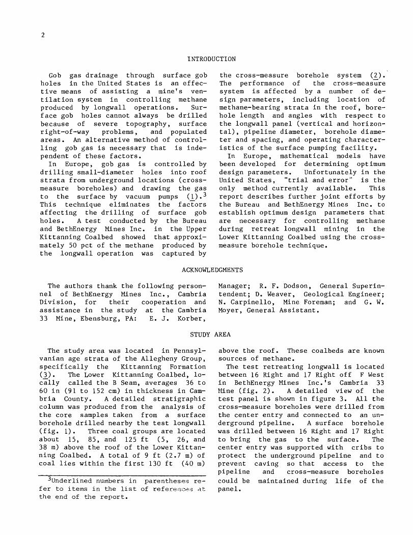
The study area was located in Pennsyl- vanian age strata of the Allegheny Group, specifically the Kittanning Formation (A). The Lower Kittanning Coalbed, lo- cally called the B Seam, averages 36 to 60 in (91 to 152 cm) in thickness in Cam- bria County. A detailed stratigraphic column was produced from the analysis of the core samples taken from a surface borehole drilled nearby the test longwall (fig. 1 Three coal groups are located about 15, 85, and 125 ft (5, 26, and 38 m) above the roof of the Lower Kittan- ning Coalbed. A total of 9 ft (2.7 m) of coal lies within the first 130 ft (40 m)
3 ~ n d e r l i n e d numbers i n p a r e n t h e s e s r e - f e r t o items i n t h e l i s t o f r e f e r e r l c e s at t h e end o f t h e r e p o r t .
above the roof. These coalbeds are known sources of methane. The test retreating longwall is located
between 16 Right and 17 Right off F West in BethEnergy Mines Inc.'s Cambria 33 Kine (fig. 2). A detailed view of the test panel is shown in figure 3. All the cross-measure boreholes were drilled from the center entry and connected to an un- derground pipeline. A surface borehole was drilled between 16 Right and 17 Right to bring the gas to the surface. The center entry was supported with cribs to protect the underground pipeline and to prevent caving so that access to the pipeline and cross-measure boreholes could be maintained during life of the panel.
Lower Kittonning Coolbed (8)
LEGEND
Sandstone
Shale
.-- ~ l ~ ~ s t o n e --.
FIGURE 1. - Stratigraphic column above Lower FIGURE 2. - BethEnergy Mines Inc.'s Combria Kittanning Coalbed. 33 Mine (Lower Kittanning Coolbed).
DRILLING EQUIPMENT AND PROCEDURES
Except f o r minor a l t e r a t i o n s , d r i l l - i n g equipment and procedures were s i m i - l a r t o those developed i n a p r i o r s tudy conducted i n t h e Upper K i t t ann ing Coalbed a t t h e Cambria 33 Mine, Ebensburg, PA (2). The f i r s t 30 f t (9 m) of t h e cross- measure borehole was d r i l l e d w i th a 4-in (10 cm) diamond co re b i t , and t h e cores were removed i n 30-in (76 cm) s e c t i o n s . The remainder of t h e ho l e was d r i l l e d u s ing a 1.9-in (5 cm) " s t r a t apac" b i t . The 1.6-in ( 4 cm) diameter d r i l l rods
were 15 i n (38 cm) long, and no cen- t r a l i z e r s were used dur ing d r i l l i n g . Af t e r completion of t h e boreholes , a 2.5-in ( 6 cm) d iameter , 20-ft (6.1 m) p l a s t i c pipe was t hen grouted 18 f t (5.5 m) i n t o t h e ho l e us ing a cement-flyash s l u r r y conta in ing 50 v o l pc t f l ya sh . An experienced two-person d r i l l crew could set up t h e d r i l l , d r i l l t h e ho l e , and in- s t a l l and g rou t t h e p l a s t i c pipe i n about t e n 8-h s h i f t s .
METHANE REMOVAL SYSTEM
E x t r a c t i o n of a coalbed by longwall mining f r a c t u r e s and breaks up t h e over- l y i n g s t r a t a and r e l e a s e s methane i n t o t h e mine workings. By cap tu r ing and t r a n s p o r t i n g methane through t h e cross- measure borehole system, methane flows e n t e r i n g t h e mine's v e n t i l a t i o n system can be reduced.
Twelve cross-measure boreholes were d r i l l e d along t h e pane l , and a l l ho l e s were connected t o a 6-in (15 cm) diameter polyethylene p ipe l ine . The gas ( a i r p lu s methane) was brought t o t h e s u r f a c e through a s tee l -cased , 8-in (20 cm) d i - ameter borehole and discharged i n t o t h e atmosphere.

FIGURE 3. - Longwall test panel.
Gas flow occurs from a cross-measure borehole only a f t e r p a r t i a l undermin- i n g of each hole and a p p l i c a t i o n of a p a r t i a l vacuum by an exhaus t e r o r vacuum pump. I n t h i s s t udy , two exhaus te rs were used ( f i g . 4 ) . The capac i ty of t h e smaller exhaus te r ranged t o 450 f t3/min (0.212 m3/s) a t a p a r t i a l vacuum of 8.65 i n Hg (29 kPa). The l a r g e r exhaus te r
r e q u i r e s a minimum flow of 350 f t 3 /min (0.165 m3/s), and maximum c a p a c i t y is 1,300 f t 3 /min (0.614 m3/s) a t a p a r t i a l vacuum of 12.6 i n Hg (42 kPa). The sma l l e r exhaus t e r was used i n i t i a l l y un- t i l t h e gas f low from t h e undermined cross-measure boreholes reached about 400 f t3/min (0.189 m3 / s ) , and t h e r e a f t e r t h e l a r g e r capac i ty exhaus t e r w a s used.

FIGURE 4. - Surface exhausters.
CROSS-MEASURE BOREHOLE DESIGN
The des ign of t h e cross-measure bore- h o l e system was s i m i l a r t o t h e des ign used i n t h e Upper Ki t tanning Coalbed s t u d i e s ( 2 , 4) : - - V e r t i c a l i n c l i -
n a t i o n ang le - 28' (0.49 r a d )
Hole l e n g t h - 280 f t (85 m)
Terminal he igh t - 132 f t (40 m)
Hor izonta l angle - 45' (0.79 r a d )
Spacing - 200 f t (61 m) on f i r s t h a l f of panel and 300 f t (91 m) on second ha l f of panel.
A l l ho l e s were surveyed a f t e r comple- t i o n of d r i l l i n g t o determine t h e a c t u a l pa th of t h e b i t through t h e roof s t r a t a . In gene ra l , t h e surveys show t h a t t h e h o l e s tu rned upward more s t e e p l y and t o t h e r i g h t because of clockwise r o t a t i o n of t h e b i t .
Genera l ly , ho l e s w i l l t u r n upward be- cause of d i f f e r e n c e i n diameters of b i t and d r i l l rods . For t h e equipment used i n t h i s s t udy , a 1.9-in (4.8 cm) diameter b i t and 1.6-in (4.1 cm) diame- t e r rods w e r e used. Consequently when d r i l l i n g , t h e f i r s t 5 f t (1.5 m) of d r i l l s t r i n g tends t o be cocked upwards i n t h e ho l e , and ho le t r a j e c t o r y t u r n s upward more s t e e p l y . Applying excess ive t h r u s t a l s o t ends t o t u r n t h e ho l e upward more
s t e e p l y . The use of c e n t r a l i z e r s , one behind t h e b i t and a second about 5 f t (1.5 m) from t h e b i t , would tend t o pre- ven t h o l e t r a j e c t o r y from t u r n i n g upward more s t eep ly . However, even wi th cen- t r a l i z e r s , excess ive t h r u s t on a b i t w i l l t u r n h o l e t r a j e c t o r y upward more s t e e p l y . To prevent t h e r e t r e a t i n g f ace of t h e a d j a c e n t pane l from pass ing t h e d r i l l i n g s i t e , ho les were d r i l l e d a s r ap id ly a s p o s s i b l e , which caused t h e ho l e s t o t u r n upwards more s t e e p l y t han planned.
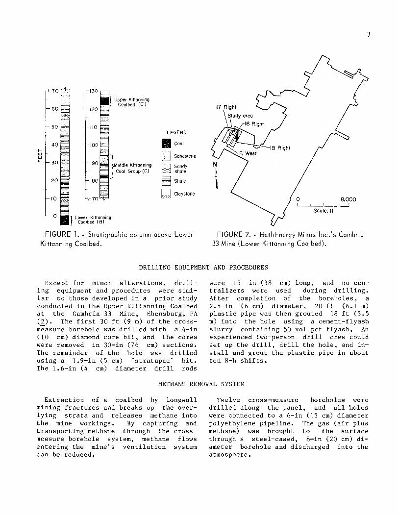
Hole l o c a t i o n s were changed i n many cases t o provide more d r i l l i n g t i m e be- f o r e t h e f a c e of t h e ad j acen t pane l reached t h e d r i l l s i t e and because of poor roof condi t ions . Consequently, h o l e spac ing was va r i ed from 170 t o 210 f t (52 t o 64 m) on t h e f i r s t h a l f of t h e pane l and from 220 t o 350 f t (67 t o 107 m) on t h e second h a l f .
F igure 5 shows t h e des ign c h a r a c t e r i s - t i c s of t h e cross-measure boreholes . The i n i t i a l i n c l i n a t i o n (column A) v a r i e d from 28" t o 33O (0.49 t o 0.58 rad) except f o r ho l e s 11 and 12, which were purposely d r i l l e d lower i n t h e p ro j ec t ed gob. Hor- i z o n t a l a n g l e (column B ) i s g r e a t e r t h a n t h e 45O (0.79 r ad ) des ign c r i t e r i o n and v a r i e d from 50' t o 65" (0.87 t o 1.13
LEGEND Cross-measure borehole number
A Initial inclination, degrees 8 Horizontot ongk, degrees C Hole length. ft 0 Terminal height of hole. ft E Height of hole at end of ;upported
length, ft F Penetration over lonawall aonel. ft
PLAN VlEW
- . . G Distance from endpo~nt to origin of Suppat pr lb~
hole, ft H Distance from stort of panel to end- ELEVATION VlEW
point of hole, ft ND Not determ~ned
FIGURE 5. - Cross-measure design characteristics.
rad) . Except f o r t h e i n i t i a l i nc l i na - t i o n s and h o r i z o n t a l a n g l e s , h o l e s 3 and 6 could no t be surveyed completely be- cause of d e b r i s i n t h e ho les .
SURFACE GOB HOLES
Surface gob ho le s have been used a t t h i s mine s i n c e 1968 t o a s s i s t i n con- t r o l l i n g methane i n gobs. Figure 6 shows a t y p i c a l borehole layout on longwall panels . Sho r t e r than normal longwall pane ls u sua l ly employ only two s u r f a c e ho les . General ly , a low-pressure ex- h a u s t e r is mounted on t h e s u r f a c e gob h o l e s t o draw t h e methane from t h e gob.
The cross-measure borehole study was conducted on a test pane l where only one s u r f a c e gob ho le could be d r i l l e d about 1,300 f t (396 m) from t h e s t a r t of t h e test pane l because of a populated a r e a on t h e sur face . Even t h i s borehole was d i s - placed about 75 f t (23 m) from t h e c e n t e r l i n e towards t h e r e t u r n s i d e of t h e long- w a l l t o avoid s u r f a c e bu i ld ings .
UNDERGROUND AND SURFACE INSTRUMENTATION
Figure 7 shows t h e underground measure- ment i n s t rumen ta t i on used i n connect ing a cross-measure borehole t o t h e underground p ipe l ine . Gas flow r a t e s ( a i r p l u s meth- ane) were c a l c u l a t e d from d i f f e r e n t i a l p r e s su re measurements w i t h a U-tube man- ometer a c r o s s t h e p re s su re t a p s of a ven- t u r i . A handheld, 0- t o 100-pet meth- anometer was used f o r determining t h e concen t r a t i on of methane i n t h e gas
f lows, and t h e p a r t i a l vacuum a t each borehole was measured w i t h a manometer a t t h e ven tu r i .
The t o t a l gas f low from t h e cross- measure system was determined by summing t h e flows from t h e i n d i v i d u a l boreholes and by measuring t h e f low a t t h e s u r f a c e through an o r i f i c e p l a t e i n s t a l l e d i n t h e s u r f a c e p ip ing ( f i g . 8 ) . The d i f f e r e n - t i a l p r e s su re a c r o s s t he o r i f i c e p l a t e

I
LEGEND x Equidistant spacing
@ Surface gob hole --- Centerline
--$. --------- -$ --------- $- - - ---
4 X + - ' X ~ X -
Direction of retreat b
bb, 3,000 to 5,000 ft , ~ d FIGURE 6. - Surface gob hole locat ions for longwol l panel.
Plastic pipe (standpipe 1,
/AY/r(\Y/AV/~Y/AY/X\V/&Y/AV / X V / ~ V / A V / / C \ Y / X \ Y / A V / ~ V / N / X \ Y / A V / x \ '
Not to scale
FIGURE 7. - Underground measurement instrumentation.

'- - 47 /---' FIGURE 8. - Dual exhauster arrangement.
was continuously recorded, and the gas concentration of methane in the gas flow flow was calculated from the differen- was measured continuously by drawing a tial pressure measurements. All gas small quantity of gas through a recording flow measurements were corrected to infrared gas analyzer. A pressure tap mine atmospheric conditions so that com- was used to measure the partial vacuum at parisons could be made between under- the inlet to each exhauster. ground and surface measured flows. The
GAS-WATER SEPARATOR SYSTEM
The strata overlying a coalbed may con- tain several water-bearing formations that are penetrated by cross-measure boreholes. Some boreholes produce water when initially drilled; others produce water when the strata are fractured by the longwall mining operation; and some boreholes do not produce water at any time. Consequently, boreholes need to be fitted with gas-water separators to pre- vent the water, if any, from entering and blocking the underground pipeline. If
the underground pipeline can be sloped so that water runs freely to one end of the pipeline, then individual gas-water separators are not necessary. The water can be discharged directly into the main pipeline and subsequently removed through a gas-water separator at a convenient locat ion. Most commercial gas-water separators
are designed to operate in a positive pressure environment. When pressure is negative, the separators malfunction.

Consequen t ly , s p e c i a l gas-water separa - t o r s must be des igned and b u i l t t o op- e r a t e i n a n environment where p a r t i a l vacuum c o n d i t i o n s e x i s t ( 5 ) . These sep- a r a t o r s r e q u i r e e x p e n s i v e m a c h i n e d p a r t s , d e l i c a t e a d j u s t m e n t s , and maintenance. The Bureau h a s developed a s e p a r a t o r t h a t o p e r a t e s i n a p a r t i a l vacuum environment , c o n t a i n s o n l y one moving p a r t , and can be c o n s t r u c t e d of p l a s t i c p i p e t h a t is read- i l y a v a i l a b l e ( f i g . 9 ) (&). T h i s d e v i c e r e q u i r e s o n l y minimal maintenance.
A f t e r a cross-measure b o r e h o l e h a s been d r i l l e d , a 20-f t (6 .1 m ) , 2.5-in (6.4 cm) d i a m e t e r p l a s t i c p i p e i s g r o u t e d 18 f t (5 .5 m) i n t o t h e h o l e . About 2 f t (0.6 m) of t h e p i p e p r o t r u d e s i n t o t h e mine e n t r y . A 2.5-in (6.4 cm) p l a s t i c "T" i s f i t t e d on t h e end of t h e p i p e ; t h i s "T" p r o v i d e s s u p p o r t f o r a 1.25-in (3.2 cm)
c o n c e n t r i c g a s p ipe . Water f lowing down t h e h o l e e n t e r s t h e annu lus between t h e two c o n c e n t r i c p i p e s and i s d i s c h a r g e d th rough a one-way check v a l v e mounted on a p i p e e x t e n s i o n from t h e "T." Gas is drawn from t h e h o l e th rough t h e i n n e r p l a s t i c p i p e , which i s f i t t e d w i t h a n end cap and i s s l o t t e d a s h o r t d i s t a n c e on i t s t o p s u r f a c e on ly . The end cap pre- v e n t s c a s c a d i n g water from e n t e r i n g t h e c o n c e n t r i c p i p e and accumula t ing i n t h e underground p i p e l i n e .
T y p i c a l l y , cross-measure b o r e h o l e s a r e i n c l i n e d abou t 30" (0.52 r a d ) . Conse- q u e n t l y , t h e v e r t i c a l h e i g h t from t h e roof t o t h e end of t h e 2.5-in (6.4 cm) p l a s t i c p i p e is about 9 f t (2.7 m). About 2 f t (0.6 m) i s added f o r t h e ex- t e n s i o n p i p e , which makes a t o t a l ver- t i c a l h e i g h t of 11 f t (3 .4 m ) . When a
2.5- in-l 0 PVC pipe
height
\ I
Water discharge Not to scale
Check valve 1
FIGURE 9. - Gas-water separator.
p a r t i a l vacuum i s a p p l i e d t o t h e h o l e , Small p a r t i c l e s of roof rock may be w a t e r accumulates i n t h e annu lus u n t i l washed down t h e h o l e and accumulate a t t h e v e r t i c a l h e i g h t of t h e w a t e r column t h e p i p e e x t e n s i o n j u s t b e f o r e t h e one- i s balanced by t h e a p p l i e d vacuum. Any way check valve . E v e n t u a l l y , t h e p i p e f u r t h e r accumulat ion of w a t e r i s d i s - e x t e n s i o n becomes blocked and w a t e r i s charged through t h e one-way check valve . p reven ted f rom d i s c h a r g i n g through t h e
For example, suppose t h e a p p l i e d vacuum i s 8 i n Hg (27.2 kPa) ; t h e n t h e v e r t i c a l h e i g h t of t h e w a t e r column i s about 9.1 f t (2.8 m). The w a t e r column e x t e n d s abou t 14.2 f t (4.3 m) a l o n g t h e h o l e i n t h e annu lus above t h e roof l i n e . The maximum p a r t i a l vacuum t h a t can be ap- p l i e d t o t h e h o l e i s about 9.7 i n Hg ( 3 3
one-way check valve . The w a t e r w i l l ac- cumulate i n t h e annu lus u n t i l t h e s l o t i n t h e g a s d r a i n a g e p i p e i s reached and t h e n d i s c h a r g e - i n t o t h e underground p i p e l i n e . Consequent ly , t h e underground p i p e l i n e shou ld be f i t t e d on t h e bottom s i d e w i t h one-way check v a l v e s l o c a t e d i n low s p o t s a l o n g t h e p i p e l i n e . When t h e s u r f a c e ex-
kPa) . I n t h i s c a s e , t h e w a t e r column may h a u s t e r s a r e s h u t o f f p e r i o d i c a l l y , t h e r e a c h t h e s l o t i n t h e c o n c e n t r i c g a s one-way check v a l v e s open a u t o m a t i c a l l y d r a i n a g e p i p e , and consequent ly w a t e r and d i s c h a r g e t h e accumulated w a t e r i n w i l l d i s c h a r g e d i r e c t l y i n t o t h e under- t h e p i p e l i n e . A l l cross-measure bore- ground p i p e l i n e i n s t e a d of through t h e h o l e s shou ld be i n s p e c t e d t o e n s u r e t h a t one-way check valve . I n t h e e v e n t t h e rock p a r t i c l e s a r e n o t accumulat ing i n c ross -measure boreho le does no t produce t h e p i p e e x t e n s i o n n e a r t h e one-way check w a t e r , t h e n t h e one-way check v a l v e re- valve . mains c l o s e d and p r e v e n t s mine a i r f rom e n t e r i n g t h e g a s d r a i n a g e l i n e .
DATA ANALYSES
LONGWALL PRODUCTION Table 2 summarizes t h e average g a s and methane f low r a t e s from t h e boreho les .
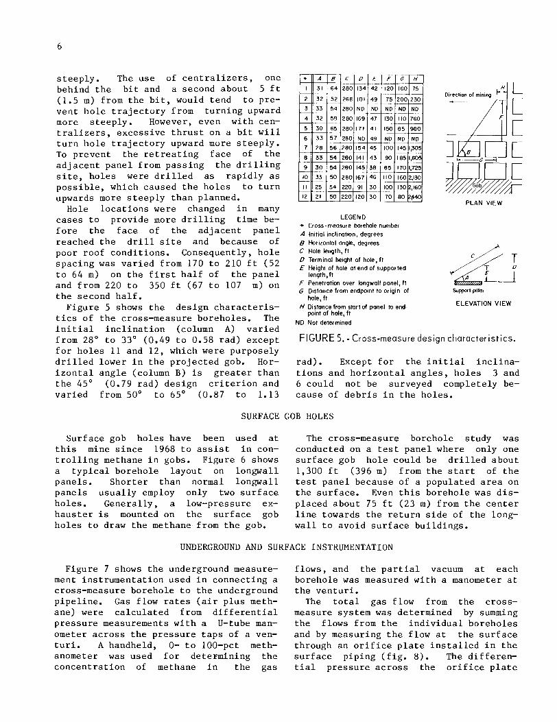
The t e s t longwal l i s 585 f t (178 m) Flow r a t e s a r e much g r e a t e r where p a r t i a l wide and 2,750 f t (838 m) long. The vacuum i s low ( h o l e s 4 , 9 , and 1 2 ) , i n d i - p a n e l was worked 3 s h i f t s p e r day b u t i n a predominant ly 3-d/wk schedu le because of t h e low demand f o r c o a l ( f i g . 10) . On working days , t h e p a n e l was r e t r e a t e d a n a v e r a g e of 40 f t / d (12 m/d). Average c o a l ' p r o d u c t i o n was 3,800 ton/d (3 ,447 m t / d ) , which i s above average c o a l pro- d u c t i o n i n a 4 - f t (1.2 m) coalbed ( 7 ) . The longwal l p a n e l was complete ly miTed i n 69 working d a y s , which were s p r e a d o v e r a 240-day i n t e r v a l and i n c l u d e d
c a t i n g a h i g h l y permeable gob compared w i t h t h o s e c a s e s were p a r t i a l vacuums a r e h i g h ( h o l e s 3 , 8 , and 10) and f lows low- e r . Approximately 71 p c t of t h e methane produced by t h e l o n g w a l l mining o p e r a t i o n was c a p t u r e d by t h e cross-measure bore- h o l e system.
t h r e e i d l e p e r i o d s of abou t 73, 32, and 10 d a y s ( f i g . 10) .
5 0 I 0 t ?
CROSS-MEASURE BOREHOLE GAS PRODUCTION
Table 1 shows a l l boreho les produced g a s e x c e p t h o l e 7. Other h o l e s ( h o l e s 1 , 3 , 4 , 6 , and 8 ) were s h u t i n f o r s h o r t p e r i o d s t o t a l i n g 6 t o 120 nonconsecut ive days d u r i n g t h e - l i f e of t h e p a n e l because o 40
of e x c e s s i v e w a t e r f low. low methane con- TIME, days
c e n t r a t i o n , o r blockage. FIGURE 10. - Daily longwall coal production.

TABLE 1. - Produc t ion h i s t o r y of b o r e h o l e s
Comments
Water problems and low methane
Shut down p e r i o d s , days
Hole
c o n c e n t r a t i o n . None. Blocked by d e b r i s . Water problems. None. Water problems. No g a s p roduc t ion . Water problems. None. None. None. None.
P roduc t ion day S t a r t u p I Terminat ion
'NO p r o d u c t i v e l i f e .
TABLE 2. - Average methane and g a s f l o w s from b o r e h o l e s
Hole I P a r t i a l vacuum, Methane I Av. f low r a t e . f t 3 / m i n
2 3 4 5 6 7 8 9
10 11 12
conc, p c t 73
3.7 5.5 1.9 3.4 3.1 ( 9 4.1 1.6 5.8 3.9 2.6
I I
I Gas 138 112 50
118 116 84
( 9 58
121 39
136 124
2 ~ o p r o d u c t i v e l i f e .
Methane 100
70 30
Most b o r e h o l e s d i d n o t produce g a s un- t i l a p a r t i a l vacuum was a p p l i e d and t h e l o n g w a l l f a c e passed 75 t o 100 f t ( 2 3 t o 30 m) beyond t h e end of t h e boreho le b u t b e f o r e t h e f a c e reached i t s c o l l a r . Holes 5 and 10 were e x c e p t i o n s . A f r e e f low of methane [60 f t 3 / m i n (0.028 m3/s ) ] was measured from h o l e 5 b e f o r e t h e f a c e reached i t s c o l l a r . A f t e r t h e f a c e passed beyond t h e c o l l a r , t h e f r e e f low s t o p p e d and a p a r t i a l vacuum was r e q u i r e d t o m a i n t a i n flow. Gas p roduc t ion oc- c u r r e d from h o l e 10 o n l y a f t e r t h e f a c e passed w e l l beyond i t s c o l l a r .
Holes 10 and 11 were d r i l l e d from t h e same l o c a t i o n ; t h e y t e rmina ted 167 and 91 f t (51 and 28 m), r e s p e c t i v e l y , above t h e mined coa lbed ( f i g . . 5 , column D ) . Tab le 2 shows t h a t t h e average g a s and
methane f lows f rom h o l e 11 were abou t 3 t imes l a r g e r t h a n f l o w s from h o l e 10, s u g g e s t i n g t h a t boreho les d r i l l e d lower i n t h e gob a r e more p roduc t ive . However, t h e p roduc t ion l i f e of t h e s e b o r e h o l e s was s h o r t because mining of t h e p a n e l was completed and t h e s t u d y t e r m i n a t e d s h o r t - l y a f t e r t h e b o r e h o l e s were undermined. I f t h e b o r e h o l e s had been d r i l l e d f u r t h e r from t h e end of t h e p a n e l , long-term pro- d u c t i o n h i s t o r y may have shown t h a t t h e c o n c e n t r a t i o n of methane i n t h e gas f l o w from h o l e 11 dropped s i g n i f i c a n t l y be- cause of i t s low p o s i t i o n i n t h e gob. gob. More t e s t s a r e needed t o e v a l u a t e t h e e f f e c t s of t e r m i n a l h e i g h t of bore- h o l e s on methane c o n c e n t r a t i o n s i n t h e gas f low.
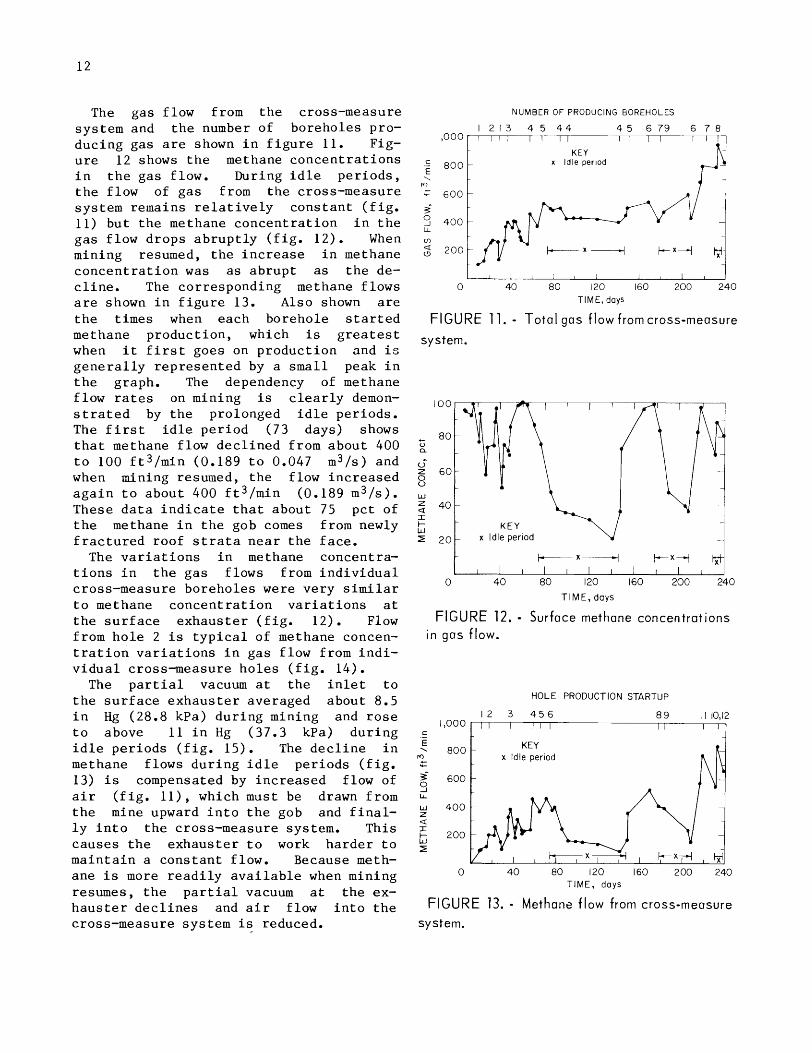
The gas f low from t h e cross-measure sys tem and t h e number of boreho les pro- d u c i n g gas a r e shown i n f i g u r e 11. Fig- u r e 12 shows t h e methane c o n c e n t r a t i o n s i n t h e g a s f low. During i d l e p e r i o d s , t h e f low of g a s from t h e cross-measure sys tem remains r e l a t i v e l y c o n s t a n t ( f i g . 11) bu t t h e methane c o n c e n t r a t i o n i n t h e g a s f low d r o p s a b r u p t l y ( f i g . 12) . When mining resumed, t h e i n c r e a s e i n methane c o n c e n t r a t i o n was a s a b r u p t a s t h e de- c l i n e . The cor responding methane f l o w s a r e shown i n f i g u r e 13. Also shown a r e t h e t imes when each boreho le s t a r t e d methane p roduc t ion , which i s g r e a t e s t when i t f i r s t goes on p r o d u c t i o n and i s g e n e r a l l y r e p r e s e n t e d by a s m a l l peak i n t h e graph. The dependency of methane f low r a t e s on mining i s c l e a r l y demon- s t r a t e d by t h e prolonged i d l e pe r iods . The f i r s t i d l e p e r i o d (73 days) shows t h a t methane f low d e c l i n e d from about 400 t o 100 f t 3 / m i n (0.189 t o 0.047 m3/s) and when mining resumed, t h e f low i n c r e a s e d a g a i n t o abou t 400 f t 3 / m i n (0.189 m3/s). These d a t a i n d i c a t e t h a t abou t 75 p c t of t h e methane i n t h e gob comes from newly f r a c t u r e d roof s t r a t a n e a r t h e f a c e .
The v a r i a t i o n s i n methane concentra- t i o n s i n t h e g a s f lows from i n d i v i d u a l cross-measure b o r e h o l e s were v e r y s i m i l a r t o methane c o n c e n t r a t i o n v a r i a t i o n s a t t h e s u r f a c e e x h a u s t e r ( f i g . 12) . Flow from h o l e 2 i s t y p i c a l of methane concen- t r a t i o n v a r i a t i o n s i n g a s f low from i n d i - v i d u a l c ross -measure h o l e s ( f i g . 14).
The p a r t i a l vacuum a t t h e i n l e t t o t h e s u r f a c e e x h a u s t e r averaged about 8.5 i n Hg (28.8 kPa) d u r i n g mining and r o s e t o above 11 i n Hg (37.3 kPa) d u r i n g i d l e p e r i o d s ( f i g . 15) . The d e c l i n e i n methane f lows d u r i n g i d l e p e r i o d s ( f i g . 13) i s compensated by i n c r e a s e d flow of a i r ( f i g . l l ) , which must be drawn from t h e mine upward i n t o t h e gob and f i n a l - l y i n t o t h e cross-measure system. Th is causes t h e e x h a u s t e r t o work h a r d e r t o m a i n t a i n a c o n s t a n t f low. Because meth- ane i s more r e a d i l y a v a i l a b l e when mining resumes, t h e p a r t i a l vacuum a t t h e ex- h a u s t e r d e c l i n e s and a i r f low i n t o t h e cross-measure sys tem i s reduced.
NUMBER OF PRODUCING BOREHOLES
1 2 1 3 4 5 4 4 4 5 6 7 9 6 7 8 i - 7 T T 1
KEY - x Idle per~od
TIME, days
F IGURE 11. - To ta l gas f low from cross-measure
system.
+x* t+" lyt .- I I I I I I I I I
0 40 8 0 120 160 2 0 0 2 4 0
TIME, days
F IGURE 12. - Surface methane concentrations
i n gas flow.
HOLE PRODUCTION STARTUP
KEY
-
0 4 0 8 0 120 160 2 0 0 240 TIME, days
FIGURE 13. - Methane f low from cross-measure
system.

0 4 0 8 0 120 160 2 0 0 2 4 0 TIME, days
FIGURE 14. - Methane concentrations i n gas
f low ftom hole 2.
a > 8 K E Y
-1 x Idleperiod
0 4 0 8 0 120 160 2 0 0 2 4 0 TIME, days
FIGURE 15. - Par t ia l vacuum measured at sur-
face exhauster.
METHANE MIGRATION THROUGH GOBS
The numbers shown i n f i g u r e 14 r e p r e - s e n t t h e d i s t a n c e s between h o l e 2 and t h e moving f a c e . During t h e f i r s t i d l e p e r i o d , t h e c o n c e n t r a t i o n of methane i n t h e g a s f low from t h e h o l e d e c l i n e d from a b o u t 90 t o 30 p c t i n 20 days. When mining resumed on day 140, t h e methane c o n c e n t r a t i o n i n t h e gas f low began t o i n c r e a s e and reached 100 p c t on day 178, when t h e f a c e of t h e p a n e l was 1 ,630 f t (497 m ) f r o m h o l e 2. During t h e second i d l e p e r i o d (day 180 t o 210) , t h e methane c o n c e n t r a t i o n a g a i n d e c l i n e d and t h e n in - c r e a s e d and reached 90 p c t a f t e r mining resumed. A t t h i s time t h e d i s t a n c e be- tween f a c e and h o l e 2 was 2,120 f t (646 m). These d a t a c l e a r l y i n d i c a t e t h a t methane m i g r a t e s through t h e gob f o r d i s - t a n c e s of a t l e a s t 2,120 f t (646 m). A Bureau s tudy i n t h e P i t t s b u r g h Coalbed showed t h a t a n i n c r e a s e i n gas f low from a v e r t i c a l gob h o l e was a t t r i b u t a b l e t o
an i n c r e a s e i n mining r a t e a t t h e f a c e , which was 2,800 f t (853 m) from t h e gob ho le .
BOREHOLE SPACING
A p p l i c a t i o n of a p a r t i a l vacuum t o a cross-measure boreho le c r e a t e s a low- p r e s s u r e zone around t h e boreho le i n t h e gob. I f b o r e h o l e s a r e p r o p e r l y spaced , t h e s e low-pressure zones o v e r l a p and c re - a t e a con t inuous low-pressure zone wi th- i n t h e gob. Methane m i g r a t i n g downward and some mine a i r and methane from lower l e v e l s i n t h e gob w i l l be drawn upward toward t h e low-pressure zone and c a p t u r e d by t h e cross-measure system. I f t h e low- p r e s s u r e zones around e a c h h o l e do n o t o v e r l a p , which i n d i c a t e s b o r e h o l e s a r e spaced t o o f a r a p a r t , t h e n methane f rom h i g h e r l e v e l s i n t h e gob w i l l m i g r a t e i n - t o t h e mine opening between boreho les .
Borehole s p a c i n g depends upon gob per- m e a b i l i t y and o p e r a t i n g c h a r a c t e r i s t i c s of t h e s u r f a c e pump o r exhaus te r . Be- c a u s e l i t t l e i s known about gob per- m e a b i l i t y , boreho le s p a c i n g i s b e s t de- t e rmined from underground i n t e r f e r e n c e t e s t s . During t h i s t e s t , a l l b o r e h o l e s a r e s h u t - i n and t h e g a s p r e s s u r e i n t h e gob i s a l lowed t o s t a b i l i z e . The bore- h o l e s a r e t h e n opened t o f l o w , e x c e p t f o r one boreho le ( t e s t boreho le ) which is moni tored f o r changes i n g a s p r e s s u r e . I f no p r e s s u r e change o c c u r s , a d j a c e n t boreho les a r e spaced t o o f a r a p a r t . I f a s l i g h t p r e s s u r e change o c c u r s , s p a c i n g i s adequate .
I n t e r f e r e n c e t e s t s were conducted on h o l e 1 n e a r t h e s t a r t of t h e pane l , on h o l e 5 n e a r t h e c e n t e r of t h e pane l , and on h o l e 11 n e a r t h e end of t h e pane l . A l l t e s t r e s u l t s were s i m i l a r t o t h e i n - t e r f e r e n c e t e s t on h o l e 11 ( f i g . 16) . When a l l h o l e s were s h u t - i n , t h e n e g a t i v e g a s p r e s s u r e i n t h e gob around h o l e 11 q u i c k l y d i s s i p a t e d , and i n 5 min, g a s p r e s s u r e i n t h e gob reached a p o s i t i v e 0.28 i n H20 (0.07 kPa) w i t h r e s p e c t t o t h e mine environment. Then h o l e s down- s t r e a m from h o l e 11 ( h o l e 2 , 4 , 5 , 6 , and 9) were open t o f low, and w i t h i n a few moments, g a s p r e s s u r e a t h o l e 11 d e c l i n e d and s t a b i l i z e d a t a p a r t i a l vacuum of 0.15 i n H20 (0.04 kPa). Hole 9 i s spaced 220 f t (67 m) from h o l e 11; t h e t e s t
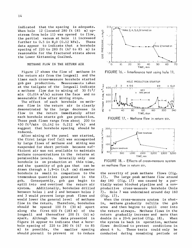
i n d i c a t e d t h a t t h e s p a c i n g i s adequate . When h o l e 12 ( l o c a t e d 280 f t ( 8 5 m) up- s t r e a m from h o l e 11) was opened t o f l o w , t h e p a r t i a l vacuum a t h o l e 11 i n c r e a s e d f u r t h e r t o 0.5 i n H20 (0.12 kPa). These d a t a appear t o i n d i c a t e t h a t a boreho le s p a c i n g of 220 t o 280 f t (67 t o 85 m) i s r e a s o n a b l e f o r t h e f r a c t u r e d s t r a t a above t h e Lower K i t t a n n i n g Coalbed.
METHANE FLOW I N THE RETURN A I R
F i g u r e 17 shows t h e f low of methane i n t h e r e t u r n a i r from t h e longwal l and t h e t i m e s each cross-measure boreho le s t a r t e d gob g a s product ion. Measurements t aken a t t h e t a i l g a t e of t h e longwal l i n d i c a t e a methane f low due t o mining of 30 f t 3 / min (0.014 m3/s) a c r o s s t h e f a c e and no measurable f low a f t e r mining s t o p s .
The e f f e c t of each boreho le on meth- a n e f low i n t h e r e t u r n a i r i s c l e a r l y demons t ra ted by t h e l a r g e d e c r e a s e i n f low i n t h e r e t u r n immediately a f t e r e a c h b o r e h o l e s t a r t s gob g a s p roduc t ion . These peak f lows range from about 200 t o 450 ft3/1nin (0.142 t o 0.212 m3/s) and s u g g e s t t h a t boreho le s p a c i n g shou ld be reduced.
A f t e r mining of t h e p a n e l was s t a r t e d , t h e f i r s t l a r g e roof f a l l was accompanied by l a r g e f lows of methane and mining was suspended f o r s h o r t p e r i o d s because s u f - f i c i e n t a i r was n o t a v a i l a b l e t o m a i n t a i n methane c o n c e n t r a t i o n s i n t h e r e t u r n s a t p e r m i s s i b l e l e v e l s . Genera l ly on ly one boreho le i s on p r o d u c t i o n a t t h i s t ime , and t h e q u a n t i t y of gob g a s t h a t can be drawn through a 1.9-in (4.8 cm) d i a m e t e r b o r e h o l e i s s m a l l i n comparison t o t h e tremendous q u a n t i t i e s g e n e r a t e d i n t h e gob. Consequent ly , gob g a s beg in t o s p i l l i n t o and over load t h e r e t u r n a i r system. A d d i t i o n a l l y , boreho les d r i l l e d between h o l e s 1 and 2 and between h o l e s 2 and 3 would p r e v e n t l a r g e peak f lows and would lower t h e g e n e r a l l e v e l of methane f low i n t h e r e t u r n . T h e r e f o r e , boreho les shou ld be spaced 100 f t (30 m) a p a r t a l o n g t h e f i r s t 600 f t (183 m) of t h e longwal l and t h e r e a f t e r 200 f t ( 6 1 m) a p a r t . Although t h e d a t a p r e s e n t e d i n f i g u r e 16 appear t o i n d i c a t e t h a t a bore- h o l e s p a c i n g of 220 t o 280 f t (67 t o 85 m) i s p o s s i b l e , t h e s m a l l e r s p a c i n g shou ld p r e v a i l t o p r e v e n t o r t o reduce
0 N I
W E 3 - cn - 1 cn Hole 12 turned on W
. J
0 10 2 0 3 0 4 0 5 0 6 0 7 0 TIME, min
FIGURE 16. - Interference test using hole 11.
HOLE PRODUCTION STARTUP C - 1 2 3 4 5 6 8 9 1 1 10,12
I I 1 I I I I KEY
TIME, days
FIGURE 17. - Methane f low in return air.
Open boreholes
100
Shut ~n boreholes o 50 o 500 1,000 1,500 2,000 2,500
TIME, min
FIGURE 18. - E f fec ts of cross-measure system
on methane f low i n return air.
t h e s e v e r i t y of peak methane f lows ( f i g . 17). The l a r g e peak methane f low around day 180 ( f i g . 17) was caused by a par- t i a l l y w a t e r b locked p i p e l i n e and a non- p r o d u c t i v e cross-measure boreho le ( h o l e 7 ) . Hole 7 was undermined around day 160 ( f i g . 17) .
When t h e cross-measure sys tem i s s h u t - i n , methane g r a d u a l l y r e f i l l s t h e gob a r e a and t h e n beg ins t o s p i l l o v e r i n t o t h e r e t u r n a i rways. Methane f lows i n t h e r e t u r n g r a d u a l l y i n c r e a s e and more t h a n double i n a 20-h p e r i o d ( f i g . 18) . When t h e sys tem i s back i n o p e r a t i o n , methane f lows d e c l i n e d t o p r e t e s t c o n d i t i o n s i n abou t 4 h. These t e s t s could o n l y be conducted d u r i n g nonmining p e r i o d s o r
o v e r weekends. Th is t e s t was on day 78 when t h e f i r s t f i v e had been i n t e r c e p t e d and were gob g a s ( f i g . 17) .
WATER PRODUCTION
A l l b o r e h o l e s were equipped w a t e r s e p a r a t o r s . No wate r c u r r e d f rom h o l e s 2 , 3 , 5 , 1
conducted b o r e h o l e s p roduc ing
w i t h gas- f lows oc-
1 , and 12 d u r i n g mining of t h e t e s t panel . I n i t i a l w a t e r p r o d u c t i o n from h o l e s 4 and 7 was 27 and 10 ga l /min (102 t o 38 L/min), re- s p e c t i v e l y . When undermined, w a t e r f low B f rom h o l e 4 d e c l i n e d t o a n e g l i g i b l e q u a n t i t y and t h a t t rom h o l e 7 d e c l i n e d t o a s t e a d y 1.5 ga l /min (5.7 L/min). A l l o t h e r b o r e h o l e s ( h o l e 1 , 6 , 8 , 9 and 12) produced w a t e r a t r a t e s from 0.25 t o 1.5 g a l / m i n (0.95 t o 5.7 L/min) a f t e r undermining.
SURFACE GOB HOLE PRODUCTION
The s u r f a c e gob h o l e produced gob g a s f o r a b o u t 6 days and was f i n a l l y s h u t - i n because of low methane c o n c e n t r a t i o n s i n t h e g a s flow. The h o l e ven ted about 1 ,200,000 f t 3 (34,000 m3) of methane dur- i n g i t s s h o r t p r o d u c t i v e l i f e . Gas pro- d u c t i o n s t a r t e d on day 156; no i n d i c a - t i o n s e x i s t t h a t t h e gob h o l e a f f e c t e d methane f lows i n t h e r e t u r n a i r from t h e l o n g w a l l ( f i g . 1 7 ) , i n s p i t e of t h e f a c t t h a t t h e end of h o l e 7 (nonproduc t ive ) is i n t h e same a r e a a s t h e s u r f a c e gob h o l e -
( f i g . 3 ) . FIGURE 19. - Gas flow into boreholes.
MIGRATION OF GAS INTO A BOREHOLE
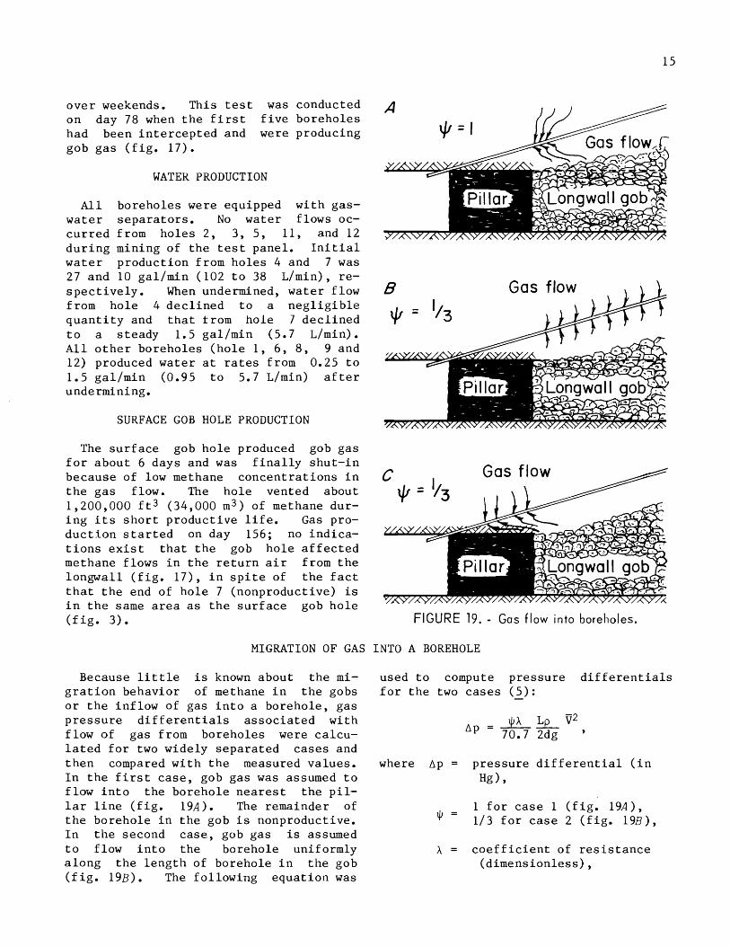
Because l i t t l e i s known about t h e m i - g r a t i o n behav ior of methane i n t h e gobs o r t h e i n f l o w of gas i n t o a boreho le , g a s p r e s s u r e d i f f e r e n t i a l s a s s o c i a t e d w i t h f low of g a s from boreho les were ca lcu- l a t e d f o r two wide ly s e p a r a t e d c a s e s and t h e n compared w i t h t h e measured v a l u e s . I n t h e f i r s t c a s e , gob g a s was assumed t o f low i n t o t h e b o r e h o l e n e a r e s t t h e p i l - l a r l i n e ( f i g . 1 9 ~ ) . The remainder of t h e b o r e h o l e i n t h e gob i s nonproduct ive . I n t h e second c a s e , gob g a s is assumed t o f low i n t o t h e boreho le uniformly a l o n g t h e l e n g t h of boreho le i n t h e gob ( f i g . 19B). The f o l l o w i n g e q u a t i o n was
used t o compute p r e s s u r e d i f f e r e n t i a l s f o r t h e two c a s e s ( 5 ) : -
where Ap = p r e s s u r e d i f f e r e n t i a l ( i n Hg) ,
1 f o r c a s e 1 ( f i g . = 113 f o r c a s e 2 ( f i g .
A = c o e f f i c i e n t of r e s i s t a n c e (d imens ion less ) ,

L = p i p e o r h o l e l e n g t h ( f t ) ,
d = p i p e o r h o l e d i a m e t e r ( f t ) ,
p = g a s d e n s i t y ( l b / f t 3 ) ,
B = a v e r a g e g a s v e l o c i t y ( f t / s ) ,
and g = a c c e l e r a t i o n s of g r a v i t y ( f t / s 2 ) .
T a b l e 3 summarizes t h e measured and c a l c u l a t e d p r e s s u r e d i f f e r e n t i a l s . I n most i n s t a n c e s , t h e c a l c u l a t e d p r e s s u r e d i f f e r e n t i a l s f o r c a s e 1 ( f i g . 19A) ap- p e a r e d t o match t h e measured d a t a more c l o s e l y t h a n c a s e 2 ( f i g . 19B). Holes 4 , 9 , and 10 were e x c e p t i o n s .
The measured p r e s s u r e on h o l e 1 0 on day 241 ( t a b l e 3 ) i s much g r e a t e r t h a n t h e computed p r e s s u r e , because t h e gob a round h o l e 1 0 a t t h i s t i m e i s t i g h t and g a s does n o t r e a d i l y e n t e r t h e ho le . On day 260, t h e measured and c a l c u l a t e d p res - s u r e s ( c a s e 1 ) a g r e e r e a s o n a b l y w e l l and i n d i c a t e t h e gob i s more permeable and g a s f l o w s e a s i l y i n t o t h e boreho le .
F o r b o t h h o l e s 4 and 9 , t h e mea- s u r e d p r e s s u r e s are much less t h a n t h e
c a l c u l a t e d p r e s s u r e s ( c a s e s 1 and 2) . However, i f one assumes t h a t gob g a s en- ters t h e segment of t h e b o r e h o l e o v e r t h e p i l l a r ( f i g . 19C), t h e n t h e measured and computed p r e s s u r e s a r e more n e a r l y i n agreement.
The d a t a p r e s e n t e d i n t a b l e 3 a p p e a r t o i n d i c a t e t h a t b o r e h o l e l e n g t h can be reduced f rom 280 t o 140 f t ( 8 5 t o 43 m), because gob g a s e n t e r s t h e b o r e h o l e s o n l y n e a r t h e p i l l a r l i n e . The remainder of t h e b o r e h o l e i n t h e gob i s nonproduc- t i v e . Reducing t h e l e n g t h of b o r e h o l e s makes t h e cross-measure sys tem more c o s t e f f e c t i v e .
An e x p e r i e n c e d d r i l l crew r e q u i r e s abou t e i g h t s h i f t s t o d r i l l a 280-ft ( 8 5 m) cross-measure boreho le . I f h o l e l e n g t h cou ld be reduced s i g n i f i c a n t - l y w i t h o u t a f f e c t i n g i t s performance, a c o n s i d e r a b l e s a v i n g s i n l a b o r c o s t s can be e f f e c t e d . For example, i f t h e d r i l l i n g t i m e i s c u t t o a b o u t f o u r s h i f t s p e r h o l e , t h e n abou t 768 person-hours a r e s a v e d i n d r i l l i n g 12 cross-measure b o r e h o l e s i n t o rock s t r a t a above a re- t r e a t i n g longwal l . Assuming a n h o u r l y r a t e of $10, a b o u t $8,000 can be s a v e d p e r longwal l .
TABLE 3. - Comparison of measured and c a l c u l a t e d g a s p r e s s u r e d i f f e r e n t i a l s
Hole
1
2
4
5
6
9
10
11
12
P r e s s u r e Measured
3.8 3.5 4.8 3.8 2.7 1.6 1.6 4.7 3.2 3.6 3.2 1.2 1.3 5.4 3.9 3.9 4.3 2.9 3.0
Day
24 49 23
247 79
207 220 122 220 207 220 220 260 241 260 220 233 234 247
d i f f e r e n t i a l , i n Hg Gas f l o w rate, f t 3 / m i n
142 105 133 96
109 116 123 129 116 95 90
138 119
3 1 113 135 119 122 101
Case 1 4.8 3.5 5.5 3.9 3.0 5.0 3.9 5.0 3.1 3.2 2.1 4.2 4.9
.2 4.4 3.7 3.7 3.2 3.4
Methane conc. , p c t
92 45
100 52 95 43
100 50
100 48
100 100
28 100
2 1 100
48 95 20
C a l c u l a t e d Case 2
8.2 6.1 8.0 5.6 5.0 8.3 6.5 8.5 5.3 5.1 3.2 7.8 9.0
.3 7.8 6.1 6.1 5.0 5.4
SUMMARY AND CONCLUSIONS
The cross-measure borehole t echnique i s an e f f e c t i v e method of c o n t r o l l i n g methane i n gobs i n t h e Lower K i t t ann ing Coalbed. About 71 pc t of t h e methane produced by t h e longwall mining opera- t i o n was cap tured by t h e cross-measure boreholes .
I n t e r f e r e n c e t e s t s and measurements of methane flows i n r e t u r n a i r i n d i c a t e t h a t borehole spac ing should be l i m i t e d t o 200 f t (61 m) except on about t h e f i r s t 600 f t (183 m) of t h e longwall , where spac ing should be reduced t o 100 f t ( 30 m). More boreholes a r e necessary n e a r t h e s t a r t of t h e longwal l t o c a p t u r e t h e l a r g e q u a n t i t i e s of methane t h a t a r e r e l e a s e d when t h e f i r s t l a r g e roof f a l l occu r s and t o p revent i t from overload- i n g t h e r e t u r n a i r system.
About 75 pc t of t h e methane i n t h e gob emanates from f r a c t u r e d roof s t r a t a n e a r t h e f ace . Prolonged i d l e pe r iods showed t h a t low methane concen t r a t i ons i n t h e gob l o c a t e d ove r 2,000 f t (610 m) from t h e f a c e i n c r e a s e t o above 90 pc t a f t e r mining resumes.
Comparisons between measured and ca lcu- l a t e d ga s p r e s s u r e d i f f e r e n t i a l s i n bore- ho l e s i n d i c a t e t h a t gob gas e n t e r s t h e boreholes c l o s e t o t h e p i l l a r l i n e , which i s about 140 f t ( 4 3 m) from t h e c o l l a r of t h e borehole. The remainder of t h e bore- ho l e i s nonproductive. Reducing borehole l e n g t h from 280 t o 140 f t (85 t o 43 m) w i l l lower d r i l l i n g c o s t pe r longwall by about $8,000 provided t h e s h o r t e r bore- ho l e s a r e a s e f f e c t i v e a s t h e l onge r boreholes . Addi t iona l exper imenta t ion i s necessary t o v e r i f y t h e s e c a l c u l a t i o n s .
REFERENCES
1. Cerv ik , J. Methane Cont ro l on Longwalls - European and U.S. P r a c t i c e s . Ch. i n Longwall-Shortwall Mining, S t a t e - of-the-Art. Soc. Min. Eng. AIME, 1981, pp. 75-80.
2. Campoli, A. A * , J. Cervik, and S. J. Sha tze l . Cont ro l of Longwall Gob Gas With Cross-Measure Boreholes (Upper K i t t a n n i n g Coalbed). BuMines R I 8841, 1983, 17 pp.
3. Iannacchione, A * , and D. G. Puglio. Geology of t h e Lower K i t t ann ing Coalbed and Rela ted Mining and Methane Emission Problems i n Cambria County, PA. BuMines R I 8354, 1979, 33 pp.
4. Scha t ze l , S. J., and G. L. F in f in - g e r , and J. Cervik. Underground Gob Gas Drainage During Longwall Mining. BuMines R I 8644, 1982, 14 pp.
5. Boxho, J., P. S t a s sen , G. Mucke, K. Noack, C. J e g e r , L. Lescher , E. J. Browning, R. Dunmore, and I. H e Monis. Firedamp Drainage. Verlag Gluckauf GmbH, Essen, 1980, pp. 130-133.
6. Campoli, A. A * , and F. Garcia . Self -Act iva t ing ~ a s / ~ i q u i d Separator . U.S. Pa t . 4,500,329, Feb. 19, 1985.
7. Peake, C. J. Longwall P r o d u c t i v i t y Shows S o l i d Growth. Coal Age, v. 89, No. 8 , Aug. 1984, pp. 61.
a U.S. GPO: 1985-505-019/20,108


![METROPOLITAN COAL LONGWALLS 301-303 BUILT FEATURES ... · Metropolitan Coal – Built Features Management Plan – Waterfall General [Garrawarra] Cemetery Metropolitan Coal – Built](https://img.pdfslide.net/doc/110x75/5e493cb4407fe522fb0e6107/metropolitan-coal-longwalls-301-303-built-features-metropolitan-coal-a-built.jpg)