Embed Size (px)
Citation preview

Methanol Production from Synthesis Gas derived from Municipal Solid Waste
Department of Chemical EngineeringUniversity of Illinois at Chicago
ChE. 397
Group Charlie: Priya Chetty, Scott Morgan, Brian Mottel, Daniyal Qamar, Sukhjinder SinghMentor: Dennis O’Brien
Instructor: Dr. Jeffery Perl 3/3/11
Group Charlie Page 1

Table of Contents
I. Abstract II. Executive Summary III. Introduction IV. Process Description V. Process Control VI. Environmental Concerns and their mitigation VII. Economics VIII. Recommendations IX. Appendices
1. Design Basis2. Block Flow Diagram3. Process Flow Diagram4. Material and Energy balances5. Calculations6. Process Simulation in ASPEN 7. Annotated Equipment List8. Economic Evaluation9. Utilities10. Conceptual Control Scheme11. General Arrangement12. Distribution and End-use Issues review13. Constraints Review14. Applicable Standards15. Project Communications File16. Information Sources and References
Group Charlie Page 2

I. Abstract
Methanol is a chemical which is used in many diverse applications. Methanol is
commonly used as a fuel, as antifreeze, and as a solvent, but can also be utilized to produce
plastics, adhesives, and dyes. The most common method for producing methanol involves
combining methane (natural gas) and water to produce synthesis gas, which is carbon monoxide
and diatomic hydrogen.
This synthesis gas is then used to produce methanol. The issue with this process is that
methane is very useful as a heating fuel which is why it is used to fulfill residential heating
needs. This method of methanol production is essentially using a fuel to produce another fuel as
the product. Our goal is to make Methanol by using a sustainable source of fuel. The source of
our synthesis gas is Chicago Land Municipal Solid Waste. We are utilizing a waste stream rather
than a fossil sourced feed stock. This will be the source of our synthesis gas. We will then
compress the synthesis gas, and feed it into a multiple feed reactor which contains Cu/ZnO/Al2O3
catalysts to produce methanol.
Unused synthesis gas will be separated from the initial product stream and recycled back
into the reactor. The initial product stream will contain methanol, along with water, as well as
other alcohols such as ethanol, and propanol. To ensure that the methanol produced will meet
the grade AA industry standard, which states that it must be 99.85% pure, the initial product will
go through a flash separator followed by two distillation columns.
Group Charlie Page 3

II. Executive SummaryBy utilizing the process outlined in this report, 99.85% pure methanol can be produced at
a rate of XXX tons per day from a feed stock of XXX tons per day of synthesis gas which will be
produced by gasification of 5,000 tons per day of municipal solid waste. Conversion of
synthesis gas to methanol is conducted in a Lurgi reactor which will utilize a Cu/ZnO/Al2O3
catalyst, and a recycle stream. The desired product will then be separated from byproducts via
flash separation, and purified using two distillation columns.
The capital cost needed to build a plant of this magnitude is $XXX. The internal rate of
return for this plant would be X%, and the payback period would be XX years.
III. IntroductionThe objective of the syngas to methanol process is to produce 1200 tons/day of grade AA
methanol for use in the chemical, automotive, and plastics industries. The syngas that is
procured for this process will have been produced by gasification of municipal sold waste.
There are many advantages to utilizing syngas produced via this method, such as; it eliminates
the need for methane, it is less expensive due to the solid waste tipping fee, and it is a much more
green technology which is important to consumers.
Group Charlie Page 4

Currently there are 90 methanol plants worldwide with an annual production of 11 billion
gallons, generating $12 billion per year in revenue. The market outlook for the future of the
methanol industry is good, with global demand expected to rise in the years to come.
The gasification plant will be located in the Chicagoland area because ample municipal
solid waste is produced there; in fact the average production is 25,000 tons per day. The
methanol plant will be located near the gasification plant, because geographic proximity will
reduce transportation costs, which also reduces the consumer price of the product.
IV. Process Description
Compressor
The syngas from the gasifier will reach the methanol synthesis plant at 300 psi. This
pressure is too low for the reactor and needs to be raised. There will be a multistage compressor
to raise the pressure to the needed value of 1200 psi. Since it is a multistage compressor there is
some pressure drop between each of the stages, due to the fact that when the gas is heated in the
compressor it will need to be cooled, and this cooling will decrease the pressure. So instead of
having an overall compression ratio of 4:1, the total compression will need to be around 4.5:1 to
overcome the pressure drop from the inter-stage coolers. The cooling water in this part of the
process will be at 90 °C, because this will eliminate for a cooling tower which is fairly expensive
to install.
Group Charlie Page 5
Reactor
Methanol synthesis is a very complex process since it is very equilibrium limited, and
quite exothermic; therefore it is imperative that the correct type of reactor is chosen to obtain the
desired results. There are many diverse types of reactors which may be used in the synthesis of
methanol, which utilize various methods of catalysis, and removal of heat from the reaction. A
significant amount of time was spent evaluating the different types of reactors to ensure that the
correct one was chosen. Below is an example of some of the reactors that were considered
along with information about each:
ICI Multiple Feed Quench Reactor
The ICI reactor uses multiple feeds to bring the reaction temperature down to the desired
value. This however requires a very high flow of air into the reactor which reduces the
effectiveness of the compressor. The reactor utilizes multiple catalyst beds to reach a conversion
of 35-40%. The maximum production rate of the ICI multiple feed quench reactor is 5000 tons
per day. The amount of syngas required to remove the heat of the reaction is in excess of that
which is able to be procured, therefore this reactor did not meet the necessary requirements for
this process.
Group Charlie Page 6

Lurgi Combination Converter Reactor
The Lurgi reactor….
Example of Lurgi Methanol Reactor courtesy of http://www.lurgi.com/
Group Charlie Page 7

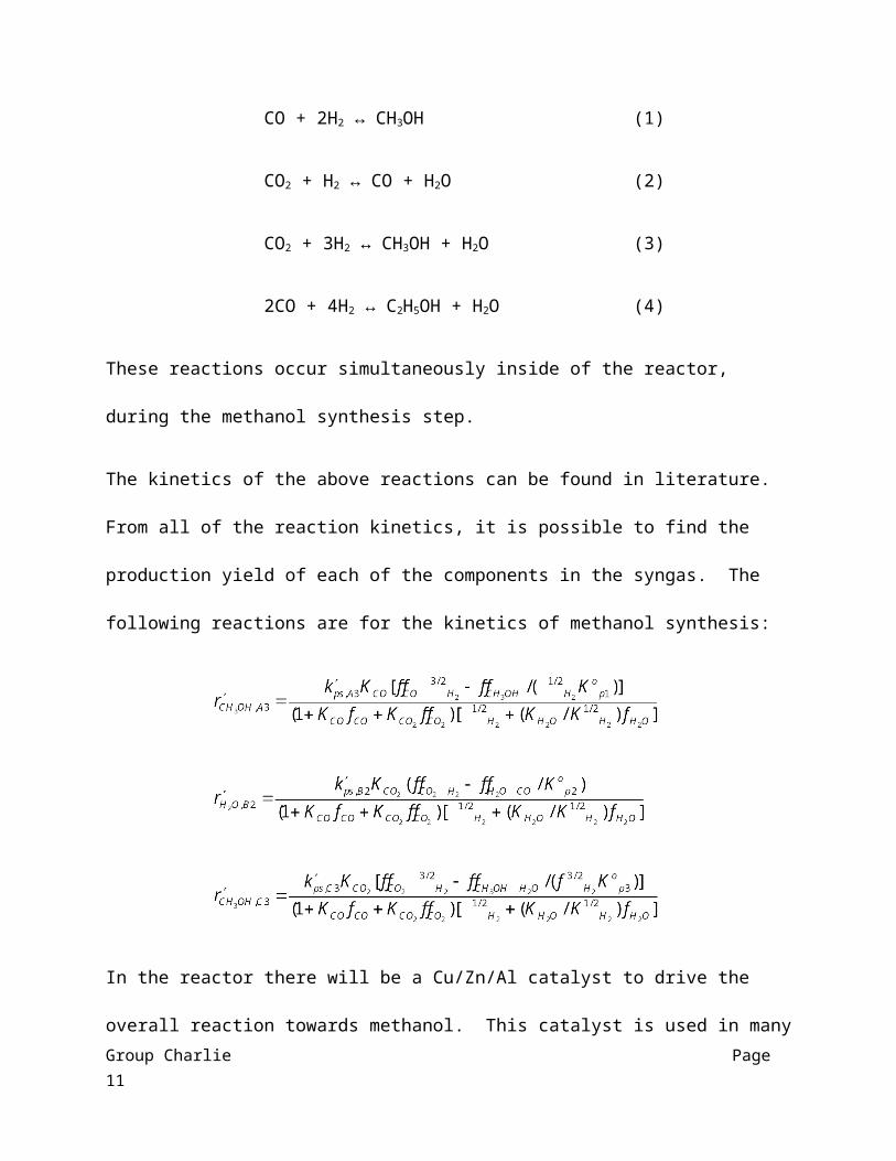
In the production of methanol from syngas, which will have a H2 to CO ratio of 3:1, there
are several reactions that will have to be considered:
CO + 2H2 ↔ CH3OH (1)
CO2 + H2 ↔ CO + H2O (2)
CO2 + 3H2 ↔ CH3OH + H2O (3)
2CO + 4H2 ↔ C2H5OH + H2O (4)
These reactions occur simultaneously inside of the reactor, during the methanol synthesis step.
The kinetics of the above reactions can be found in literature. From all of the reaction kinetics, it
is possible to find the production yield of each of the components in the syngas. The following
reactions are for the kinetics of methanol synthesis:
In the reactor there will be a Cu/Zn/Al catalyst to drive the overall reaction towards methanol.
This catalyst is used in many other reactors. The poisons of this specific catalyst are sulfur,
chlorine, CO2, and high temperatures. So in order to ensure that the catalyst life can stay at a
Group Charlie Page 8

reasonable time, the syngas that is fed into the reactor must have none of the above chemicals,
and the temperature of the reactor will need to stay at ____ F. The conversions are 40% for
reaction 1, 13% for reaction 2, 2 % for reaction 3, and 2% for reaction 4.
After the syngas has been reacted it will be at ___psi and ___F. The reacted gas will then
go through several pieces of equipment until it reaches the distillation columns for purification of
the product. The gas will need to be split for a recycle feed and remaining gas. The remaining
gas will have a high amount of crude methanol and fewer impurities than before. After this the
stream will be put through a condenser and heat exchanger in order to have the methanol in the
liquid phase and to be at a much lower temperature. Then the crude methanol is put through a
flash tank and finally to the distillation unit.
Heat Exchangers
Since many of the different pieces of equipment throughout the process need the syngas
or methanol at different temperatures, there will be two several heat exchangers throughout the
entire process. These particular heat exchangers will be a shell and tube heat exchangers, which
consists of a series of tubes. One set of these tubes contains the fluid that must be either heated
or cooled. The second fluid runs over the tubes that are being heated or cooled so that it can
either provide the heat or absorb the heat required. The fluid used in this case will be water. A
heat exchanger will be present after the multi-stage compressor in order to utilize the energy
from a high compression process. The second heat exchanger will be present after the reactor.
The reactor will be producing heat at an amount of ___, which can be utilized with this heat
exchanger. The first heat exchanger will have an area of ___, with ___ inner tubes having an
inner and outer diameter of ___ and ___ respectively. The second heat exchanger will have an
Group Charlie Page 9

area of __, with __ inner tubes having an inner and outer diameter of __ and __ respectively. The
energy balances around the heat exchangers can be found in the appendix, and they show how
much energy is needed to run each of them.
Distillation Columns
In order to obtain the grade AA methanol at the end of the process, there will need to be
two distillation columns installed. Both of the columns will need both condensers and reboilers
on them. After the second distillation column the methanol will be pure enough to sell as Grade
AA Methanol. The first distillation column will need to be at 31psi, 118°F, have 15 trays, and
the feed will be located above the ___th tray. The second distillation column will need to be at
31psi, 188°F, have 25 trays, and the feed will need to be at the ___th tray to obtain to correct
purity of methanol. After the first distillation process there will be water, ethanol, and other
higher hydrocarbons, along with the methanol. Majority of the methanol will be in the bottom
stream, including water and ethanol, which will then be fed to the second distillation column.
After the second distillation column, methanol will be present the distillate stream and the water
along with methanol and ethanol will be in the bottom stream. The water will be used for either
cooling another part of the process, or it could be heated to produce steam to be used in a heat
exchanger or to power some of the necessary equipment. The ethanol and higher hydrocarbons
will need to be separated from methanol and then they can be sold to a different company to be
used for a different process. Using ASPEN it is possible to find the dew and bubble points of the
streams exiting the columns. From all of the information, the height of the columns can be found
and from that the sizing.
Group Charlie Page 10
V. Process Control
A control process is very important in the aspect of manufacturing a quality product.
This can be assured by having the quality designed into the product and also into the
manufacturing process. Achieving this will allow the use of the process control to ensure that
the methanol produced meets the standards of grade AA methanol. At this point, the design
basis is not set to ensure a complete process control. However, there are a few vendors that
provide process control solutions.
Methanol@Max provided process controls specifically for methanol production plants.
They use particular software, which connects to the DCS and controls. This helps to optimize
the plant minute by minute, every hour of the day, every day of the year. The software does use
the PLC method. The program will reduce the variance in the parameters and reduce the need
for operator intervention. This will also help in improved separation, reduce energy
consumption, and improve the overall plant stability. Maximizing conversion and increasing
methanol production will be the key components of this software. Also, maintaining the
reactor’s parameters and adjusting them accordingly to the software will help ensure
productivity.
VI. Environmental Concerns and their mitigation
Methanol is highly flammable and may result in fire and explosive hazards, therefore
fireproof walls must be incorporated in the plant design to ensure personnel safety. Furthermore,
respirators and gloves must be utilized while working in areas of high vapor methanol
concentrations since prolonged human exposure to methanol has resulted in headaches,
Group Charlie Page 11

dizziness, nausea, gastric upsets, blurred vision, and blindness. Humans should not be exposed
to methanol concentrations greater than 198ppm based on OSHA regulations. Overall, methanol
does not pose a high hazard to health; however, effective procedures must be implemented to
ensure the health and safety of the personnel.
Methanol synthesis generates CO2 resulting in greenhouse gases emissions into the
atmosphere and over long term global warming. In addition, CO2 is heavier than air, therefore,
increasing its tendency to leak through open valves; therefore, stringent guideless must be
executed while operating valves. To ensure environmental concerns, the plant will abide to EPA
and all other environmental regulation agencies and never discharge material that is detrimental
to the environment without utilizing proper guidelines.
The plant will abide by the waste water stream regulation proposed by the municipal
waste water treatment agency. Most heavy metals in the slag or fly ash flue can be either used in
asphalt construction or converted to fine, gritty material similar to sand respectively. Remaining
heavy metals which may have run into the waste water can be removed through flocculation and
precipitation and discarded as chemical waste. Further research will be conducted to ensure the
processes discussed have competing edge, and all technological advances to impede harmful
environmental impact will be embedded in the plant design.
References
Law , Nicole, Caitlin Nichols, and David Tamayo. "Final Report: Methanol Synthesis." Chemical
Engineering Program (2008): 11-14. Web. 2 Mar 2011.
Amirkhas, Elton, Raj Bedi, Steve Harley, and Trevor Lango. "Methanol Production in Trinidad and
Tobago." Final Report (2006): 7-8. Web. 2 Mar 2011.
Group Charlie Page 12

VII. Economics
Recommendations
With all industrial processes there will be many recommendations to ensure that the process
would work both efficiently and economically. Some things that could change throughout our process
would be reactor conditions, catalyst for the reactor and CO2 removal, and conditions for any other
piece of equipment. Changing conditions for any piece of equipment would help to decrease the price
of the process, but on the other hand it could cause inefficiency in the system. A cost evaluation would
have to be preformed not only on the entire system but each piece of equipment to ensure that the
process can make the most profit. Any piece of equipment that needs high pressure or temperature will
increase the cost of that equipment. If the process was able to make the same amount of final product
with lower pressure or temperature, this would decrease the price of installment and increase the final
profit.
Catalysts are used in almost all chemical productions nowadays and choosing the best catalyst
for the process is extremely important. We are using a Cu/Zn/Al catalyst for the methanol synthesis
from syngas, and it seems to be the same one that is used in industrial processes for methanol synthesis.
Since catalysts are extremely expensive the choice of the correct one is vital. If there were to be a
cheaper or one that produced higher yields, they would need to be considered in our process. There is a
lot of research in the field of catalysis, and ones of the future seem that they will be able to make
processes run at lower conditions, which will in turn create lower prices on equipment.
Group Charlie Page 13

The most expensive part of our process, along with industrial processes, is the reactor to
produce crude methanol. This is due to the fact that very high pressure is needed to ensure the crude
methanol is produced with the fewest impurities. Our reactor is running at _____ psi and ____°F. If it
were possible to lower both pressure and temperature in the reactor, this would decrease the overall
price of the process. The Lurgi reactor seems to be the best reactor for the methanol synthesis reaction,
because it does not require an excess amount of syngas to cool it like the ICI Synetix reactor. There
could be other reactors better suited for the process, but it seems that the Lurgi will be the most cost
effective and efficient.
VIII. Recommendations
IX Appendices
Appendices1. Design Basis
By utilizing the process outlined in this report, 99.85% pure methanol can be produced at
a rate of XXX tons per day from a feed stock of XXX tons per day synthesis gas which will be
produced by gasifying 25,000 tons per day of municipal solid waste. Conversion of synthesis
gas to methanol is conducted in a LURGI quench reactor which will utilize a Cu/ZnO/Al2O3
catalyst, and a recycle stream. The desired product is then separated from byproducts via flash
separation followed by two distillation columns. Ideally the plant would be located in the
Group Charlie Page 14

Chicagoland area, because this is where the synthesis gas feedstock will be produced, and
geographic proximity will reduce transportation costs. The capital cost needed to build a plant
of this magnitude is $XXX. The internal rate of return for this plant would be X%, and the
payback period would be XX years.
2. Block Flow Diagram
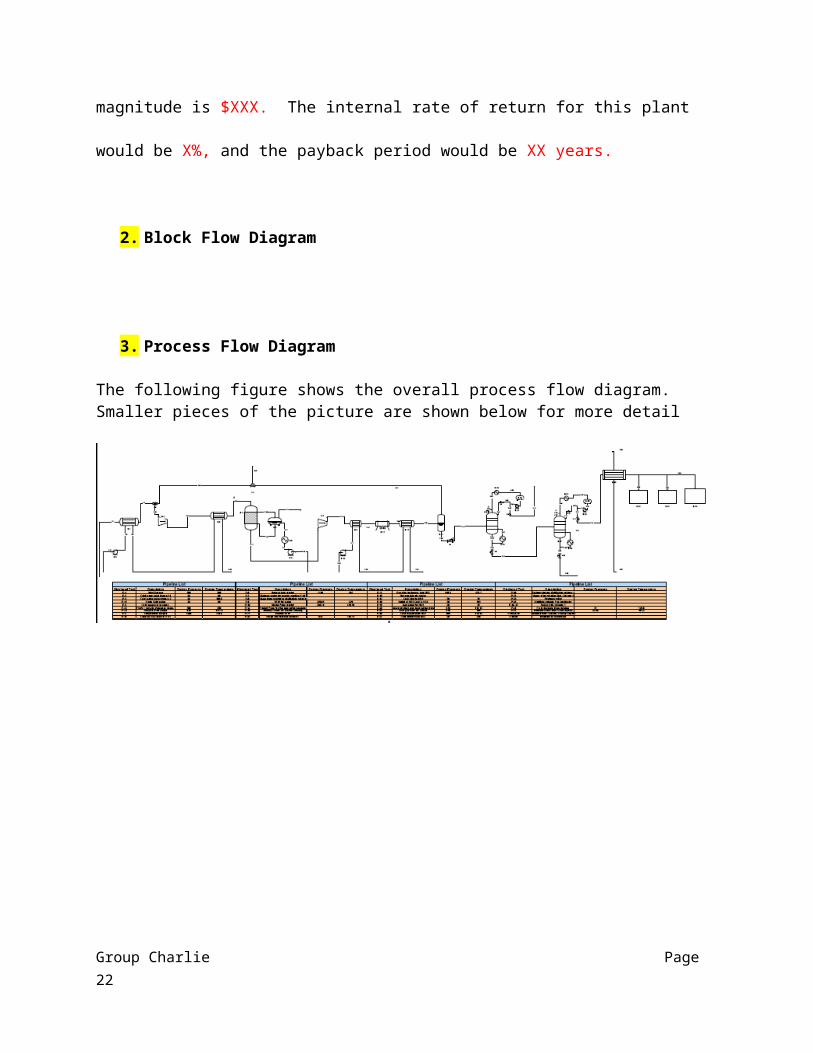
3. Process Flow Diagram
The following figure shows the overall process flow diagram. Smaller pieces of the picture are shown below for more detail
Group Charlie Page 15

This figure shows the first heat exchanger, compressor, and the second heat exchanger.
Group Charlie Page 16

This figure shows the stream coming into the reactor, the steam drum for the reactor, the turbo expander, and finally a heat exchanger that cools the product down.
Group Charlie Page 17

This figure shows an air cooler, a heat exchanger, and then the flash drum. The stream leaving the flash drum on the top is the recycle stream that loops back to join fresh syngas into the compressor.
Group Charlie Page 18
This shows the final step of the process where crude methanol is put through distillation columns and grade AA methanol is produced(P-64)
Group Charlie Page 19

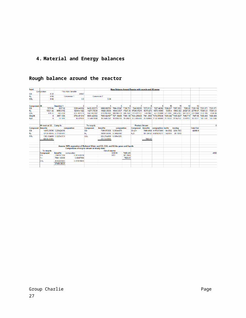
4. Material and Energy balances
Rough balance around the reactor
Group Charlie Page 20

5. Calculations
Equipment optimization procedure:
Heat exchanger (shell and tube) sizing technique utilizing Seider method
1.) Calculate R and S:
correlation factor, function of fluid temp, number of tube and shell passes and is correlated as a function of two dimensionless temp ratios:
2.) Calculate F:
correlation factor F t for 1-2 heat exchangers- 1 shell pass, 2 or more tube pass heat exchanger
3.) Calculate log mean temp (countercurrent flow)
T1 inlet shell fluid temp
T 2 outlet shell fluid temp
t 1 inlet tube side temp
t 2 outlet tube-side temp
Group Charlie Page 21
4.) Calculate Q and UA
assume: U = 100 (BTU/F*ft^2*h)
5.) Calculate tubes required using pipe parameters from Towler.
6.) Based on the number of tubes, utilize Seider Table and obtain the closest number of tubes with corresponding shell diameter
7.) Calculate shell side and tube side heat transfer coefficient correlated with the Reynolds number
8.) Calculate overall heat transfer coefficient
http://www.chemstations.com/content/documents/Technical_Articles/shell.pdf
Flash Unit
1.) Calculate max vapor velocity
Group Charlie Page 22

2.) Calculate minimum diameter
3.) Calculate liquid height
4.) Calculate vapor height H v = (pv/ Y)
Y= specific weight of fluid
5.) Calculate overall length
6.) Find L/D ratio7.) If L/D > 6, increase D and repeat 3-6 steps
Multi-tubular, Ideal plug flow reactorAssume steady state and isothermal conditions
1.) Reactor equationat steady state, no accumulation, therefore
2.) Integrate above equation to find volume yields
Group Charlie Page 23

3.) Final simplified power law expression
4.) Final complicated power law expression
http://rshanthini.com/tmp/CP303/set4.pdf
Equipment Cost procedure:
Cost of Pumps
Cost of centrifugal pump is based on volumetric flowrate and head required
1.) Utilize cost equation
Pc is the power consumption
Group Charlie Page 24

S is the sizing factor for the pump
2.) Utilize sizing and power consumption equation respectively to plug into cost equation
Pc (power consumption) in HP
Q (flowrate) in Gal/min
H (pump head) in Ft
(density) in lbs/galnp = -0.316 + 0.24051* (lnQ)-0.01199*(lnQ)^2 (fractional efficiency of the pump) in
dimensionless units
nm = 0.80 + 0.0319 * (lnPc)-0.00182 * (lnPc)^2 (fractional efficiency of the motor) in dimensionless units
3.) Applying Seider’s value, calculate purchasing cost utilizing the equations
Pump: Cp = Ft * Fm * Cb
Motor: Cp = Ft * Cb
Ft (type factor) 2.7
Fm (material factor) 1.0
Cost of Compressors
Group Charlie Page 25

I.) Purchase cost values obtained from Garrett and Walas (1988) for electric motor drive, cast iron or carbon-steel construction since Cp= Cb
II.) For other drives and materials of construction
Cp = Fd * Fm * Cb
Drive Fd Material Fm
Steam turbine 1.15 Stainless steel 2.5
Gas turbine 1.25 Nickel Alloy 5
Cost of Methanol Synthesis Reactor
Utilize shell and tube exchanger approach
Fixed head
A is area for heat exchanger in square ft.
Cb = exp (11.0515-0.9228(ln(A))+0.09861(ln(A))^2)
Fm = a+((A/100)^b)
Fp = 0.9803 + 0.018*(P/100)+0.0017*(P/100)^2
FI values can be obtained in Seider and Seader
Group Charlie Page 26
Cp= Fp*Fm*FI*Cb
Base and Purchasing cost of the MSR
Type P a b A Fm FI Fp Cb Cp
Psig sqft $ $
Fixed 1000? 418,879?
1 1 1.33 5,302,257?
7,053,593?
* data need to be verified through aspen simulation and operating parameters keep changing.
Cost of Distillation Columns
*need operating conditions and dimensions
Towers for 9,000 < W < 2,500,000 lb (?)
Cv = exp (7.0374+0.18255(ln(W))+0.02297(ln(W))^2
Towers for 3 < Di < 24ft and 27< L<170 ft
Cpl = 237.1 * (Di)0.63316*(L)^0.80161
Group Charlie Page 27

Weight calculation: W = pi()*(Di+ts)*(L+0.8Di)*ts*rho
For Po min = 10 psig
Po > 1000psig use Po= 1.1* Po and neglect equation below
Pd = exp (6.60608+0.91615(ln(Po))+0.0015655(ln(Po))^2)
tp= (Pd*Di)/(2S*E-1.2*Pd)
tp must be greater than a minimum value for rigidity based on the diameter
S is the maximum allowable stress of the shell material, at the designed temp in lbs per square inch
E is the fractional weld efficiency
6. Process Simulation in ASPEN:
An Overall process in ASPEN is shown below, each section is then broken down for simplicity
Group Charlie Page 28

Compression:
Group Charlie Page 29

Reactor:
Separations Train:
Group Charlie Page 30

Simulation Detail:
The process was simulated in ASPEN and the results were used for sizing calculations and reactor details.
REACTOR:
The process was started with a simple RSTOIC reactor:
The inlet flow was defined to be 1700 tpd, temperature of 518 F and a pressure of 1190 psi. A pressure drop of 10 psi was taken through the reactor.
The temperature and pressure were defined as in the screen above. These values were obtained from literature. Furthermore four reactions were defined as below, with conversions taken from literature:
Group Charlie Page 31

The new button is hit to add new reactions and this is where the reactants, products, and the conversions are defined:
Group Charlie Page 32

Compressor:
After adding the reactor, a compressor was added but since the feed syngas was too hot to be fed to a compressor it was cooled using a heat exchanger. To map the compressor in ASPEN the following window was used:
Only vapor phase (selected in the convergence tab) was used through this condenser since only syngas and some recycled components well above their boiling points will be going through the compressor. The discharge pressure was the only number required for this unit and it was set at 1200 psi.
Heat Exchangers:
Several heat exchangers were used through the whole simulation. There was one before the compression train, another one cooling down the compressed syngas. Two more heat exchangers were used to cool down the products from the reactor, and finally another one was used to simulate air coolers. The hot stream outlet was the only specification made for the heat exchanger block. Cooling water stream temperature and flow rates going into heat exchangers were also defined. This was just
Group Charlie Page 33

about enough water to bring the temperature of the stream down to the desired temperature. The following pictures show how they were modeled:
The pressure drop was defined as 5 psi for all the heat exchangers.
Group Charlie Page 34

7. Annotated Equipment List:
Refer to the PFD for the equipment naming
E-12 Air Cooler
The air cooler is used between the third and fourth heat exchangers. It will cool the stream
between these two pieces of equipment so that the fourth heat exchanger can use the crude methanol
stream.
E-4 Steam Drum
This piece of equipment is the steam drum that is used for the reactor. The reactor uses
saturated water to cool it and produces steam from the heat created from the reactions that occur. The
steam drum sends water to a pump and receives steam from the reactor that will be condensed so it can
be used again to cool the reactor.
E-35 Condenser
This condenser is used to turn the final grade AA methanol produced from the second
distillation column into a liquid. After the methanol is in liquid form it will be sent to several storage
tanks.
E-32, 33, and 34
These three tanks are shown in the PFD to show where the final product will be collected. Three
tanks are shown, but in reality there will be a total of 11 tanks that will be able to hold the methanol
product. The methanol will be at 99.85% purity, which is defined to be sold at grade AA.
Heat Exchanger 1
Group Charlie Page 35

The first exchanger is used to cool the synthesis gas from 500°F to 458°F to be used in the
compressor unit. Cooling water is used on the tube side of the exchanger in order to cool the syngas.
The water enters at 80°F and 20 psi, and then leaves the exchanger at 169.79°F and 20psi. This
exchanger will be run at 218°psi. The heat transfer area of this heat exchanger 87.72 ft2.
Heat Exchanger 2
The second heat exchanger is another shell and tube heat exchanger. It will receive the
compressed syngas from the condenser and will send the gas to the reactor at a much lower
temperature. The syngas will enter at 1200 psi and 716.63°F and then leave at 1190 psi and 482°F.
Cooling water will be used on the tube side of the exchanger in order to cool the syngas. The heat
transfer area of this exchanger is 1,119.8 ft2.
Heat Exchanger 3
The third heat exchanger in the process will be a shell and tube heat exchanger. It will receive
the stream from the turbo expander and sent it to another heat exchanger. The stream will consist of
CO, H2, CO2, Methanol, N-Butanol, and Ethanol. The stream will enter at 648.3 psi and 424.1°F and then
will be sent to the fourth heat exchanger at 638 psi and 350°F. Cooling water will be used in order to
cool the stream inside of the exchanger. The hot water that is taken out of the heat exchanger will be
sent into the fourth heat exchanger to be used as the cold stream. The heat transfer area of the third
heat exchanger is 366.1 ft2.
Heat Exchanger 4
The fourth heat exchanger will take the stream from the third heat exchanger and send it to the
flash column. The stream will enter at 638 psi and 350°F, and then be leaving at 638 psi and 118.13°F.
The heat transfer area of this heat exchanger is 61,006 ft2. Cooling water will once again be used in
Group Charlie Page 36

order to cool the stream inside of the heat exchanger except the colder stream will be from the third
heat exchanger.
Pump E-36
This pump is used in order to pump the syngas received from group Delta into the first heat
exchanger. Due to pressure drop in pipes, this pump is used to ensure that the first heat exchanger
receives then clean syngas at the pressure specified in the heat exchanger.
Pump E-5
This pump is used to pump the cooling water into the first heat exchanger. Since there is a
pressure drop in piping a pump is used in order to ensure that the cooling water will enter the heat
exchanger at the correct pressure.
Pump E-38
This pump is used between the steam drum and the reactor. Since water is needed to cool the
reactor, this pump is used to pump the water from the steam drum to the reactor.
Pump E-9
This pump is used to pump cooling water into the steam drum. This is used to cool the steam
that is produced from the reactor so that it condenses the steam back into water.
Pump E-37
This pump is used on the purge stream. It will pump the purge stream from the recycle stream
to a combustion unit because there will be a large amount of CO2 in the stream and that cannot be put
into the atmosphere.
Group Charlie Page 37

Pump E-10
This pump is used to pump cooling water into the third heat exchanger. After the pump the
water will be at 70°F and 20 psi.
Reactor
The reactor is a Lurgi reactor that takes in syngas at 1190 psi and 482°F to produce crude
methanol and other products. After the main reaction occurs, along with other side reactions, the
product stream leaves the reactor at 1200 psi and 518°F. Since the reaction creates a lot of heat, water
will be fed into the reactor to produce steam. This steam will be condensed in order to keep cooling the
reactor. Inside of the reactor there will be the Cu/Zn/Al catalyst. This catalyst is used in order to keep
the pressure needed to run the reaction lower than without a catalyst.
Compressor block
In ASPEN this is shown as one compressor, but in reality it is a multistage compressor. The
compressor unit takes the syngas from the first heat exchanger at 300 psi and 458°F, and then increases
the pressure to 1200 psi which is needed to run the reactor. When pressure increases so does the
temperature which will leave the compressor unit at 716.63°F. In order to obtain the high pressure the
compressor will need to have 44,391 HP. The exiting stream from this unit will be sent to a second heat
exchanger before entering the reactor.
Turbo Expander
Since the reactor is at such high pressure, a turbo expander is needed downstream in order to
decrease the pressure quickly. The crude methanol stream from the reactor, which enters the turbo
Group Charlie Page 38

expander, will enter at 1200 psi and 518°F. After going through the expander the stream will be at 648
psi and 424°F. This exiting stream will be sent to the third heat exchanger to cool it before the stream
heads to the flash column. The turbo expander will be able to drive a turbine to produce 7,726 HP, and
has an isentropic efficiency of 0.72 or 72%.
Flash column
This piece of equipment is used to take the crude methanol stream and separate it into two
streams. The stream enters the flash column at 638 psi and 118°F. After going through the column the
vapor is sent back to the compressor as a recycle stream at the same temperature and pressure. The
liquid stream from the flash column is sent to an expansion valve to decrease the pressure before
distillation. The liquid stream is still at the same temperature and pressure but the composition of the
stream is different than the vapor stream.
Expansion Valve
The expansion valve is used to decrease the pressure of the liquid crude methanol stream
before it reaches the distillation columns. The stream enters the valve at 638 psi and 118F, and then
leaves at 31.5 psi and 87.8°F. This temperature and pressure is needed for the distillation column to run
effectively.
E-20 and E-29
These two drums are used to hold the distillate that is formed from the two distillation columns.
They will hold the distillate so it can condense and then be pumped back into their respective distillation
column.
Group Charlie Page 39

E-18 and 30 are reboilers
E-19 and 31 are condensers
Distillation Column 1
Distillation Column 2
8. Economic Evaluation
Economics
Windy City Methanol has faith that the project under-hand will be financeable if various contractual
arrangements being negotiated with group Delta are satisfactorily executed. The complexity of the
project makes it essential for credible parties, viable technology, profitable economic basis, and
adequate incentives to be implemented for the project to be successful. Windy City Methanol believes it
has identified all major risk areas affiliated with the project, and will provide the types of risk protection
required by investors and interest parties to attain project financing. The following sections provide
detail on the economic sector of the project, contractual arrangements established, and type of risk
Windy City Methanol anticipates.
Capital Cost:
The project’s earlier estimates were re-evaluated and modified to reflect more accurate figures. The
largest modification to the project was utilizing a Lurgi methanol reactor as opposed to the traditional
ICI quench reactor. The total equipment cost for the project is estimated to be slightly over $43 million.
The following table shows a breakdown of the capital costs including a contingency reserve allocated for
any fiscal disparities during the construction of the Windy City Methanol plant.
The funds required to complete the Project are estimated below (in US dollars).
The installation factor figures were obtained from the “Plant Design and Economics for Chemical Engineers” by Peters & Timmerhaus.
Group Charlie Page 40

Total Installed Costs
Equipment sub-total $ 43,969,504
Direct Costs Factor Cost
Piping 0.68 29,899,262
Instillation 0.47 20,665,667
Buildings 0.18 7,914,511
Electrical installation 0.11 4,836,645
Service facilities 0.70 30,778,652
Controls and valves 0.36 15,829,021
Subtotal 109,923,760
Indirect Costs Factor Cost
Construction Expenses 0.41 18,027,496
Supervision and Engineering 0.33 14,509,936
Legal Expenses 0.04 1,758,780
Contingency 0.44 19,346,581
Subtotal 53,642,794
Total Capital Investment 207,536,058
Please see “economic tables” for a detail breakdown of all the capital costs and descriptive equipment list.
The following table shows the low and high ranges of capital costs based on cost estimation (in millions of US dollars).
Low Likely High
Plant Cost 207 209 300
Vessel Cost 22 32 35
Land Cost (75 acre) 28 37 75
Total 257 278 410
Group Charlie Page 41

Windy City Methanol estimates the total cost of the Project will be approximately $245 million and the
loan attained by a reputable bank will be used to finance 100% of the cost during the construction
period. Upon completion of the plant, approximately $61 million of the equity from the owners will be
used to reduce the outstanding bank debt. The remaining $184 million debt will be repaid over the next
19 years of the plant life. The sole purpose of financing the cost of designing, building and equipping the
Windy City Methanol plant is to construct a facility capable of producing 3,200 TPD of grade AA
methanol. The plant will be build over a 75 acre field located in Gary Avenue Indiana near Delta’s
gasification plant thus eliminating the transportation cost of the feedstock. Syngas will be supplied
under a long term contract and the methanol will be sold under a long term agreement with a
reputable, major US company. All necessary authorizations and design specifications, including all
relevant infrastructure development essential for normal operations for the project will be attained by
the end of the test period. Windy City Methanol believes that equity investors will be seeking a
minimum internal rate of return in the range of 16%-18% per annum. This minimum return is obtained
at a methanol price of $ 1.35 per gallon, and $ 200 per ton of feedstock.
Sensitivities and Assumptions:
The financial model is structured to reflect a realistic and feasible undertaking. The project model is
developed within the following parameters.
Selling price of methanol is $1.35 per gallon
Feedstock price of syn-gas is $ 200 per ton
Tax rate is 40%
Inflation rate is 0%
Contingency is $ 19 million
Total costs are $ 245 million
The internal rate of return (IRR) has be computed for three methanol prices; the results are shown
below:
Group Charlie Page 42

Price of Methanol Cost of Syn-gas Feedstock (dollars/ton)
dollars/gal $200 $250
1.35 (base price) 16.00% 6.73%
1.50 41.68% 34.90%
1.75 96.30% 69.62%
Windy City Methanol believes a 16-18% IRR is highly attractive return for equity investors. The table
shows that this is easily attainable for all cases except for the scenario where the syngas feedstock costs
$250/ton and the methanol price is $1.35 per gallon. Based on historic methanol market prices patterns,
Windy City Methanol believes that a market price of $ 1.35 per gallon is realistic since there is increased
demand with limited world supply. A futuristic increase in methanol market prices is highly promising
since crude oil price is highly susceptible to political turmoil and is a limited resource.
Risk Profile
Market Risk: Inaccurate demand estimates. The selling price of methanol is not economically feasible for the project.
Protection: Attain a long term methanol purchase contract with a large, creditworthy US Corporation.
Syngas Supply Risk: Inaccurate supply estimates. The price at which syngas is bought is not economical for the project.
Protection: A long term syngas supply contract with a fixed price and a pledge of adequate MSW reserve to meet contractual agreement between Windy City Methanol and Group Delta.
Group Charlie Page 43

Construction Risk: Construction overruns due to factors such as poor cost estimates, inflation, and construction delays caused by environmental or regulation mishaps. Overruns can cause funding problems and make the project uneconomical.
Protection: Fixed price contract agreements. Orchestrate several feasibility studies on cost estimates and implement stringent construction deadlines.
Operational Risk: Operation interruption caused by various situations such as plant failure, malfunctions, prolonged maintenance and repair, and natural disasters.
Protection: Have business interruption insurance to pay debt caused by plant failure or natural disaster.
Legal Risk: Long-term contracts among twp parties can result in legal disputes.
Protection: Attain high-quality legal advice. Have a devisable dispute settlement mechanism.
Labor-related Resources and Technical Feasibility:
Special skills are essential for a planned project; therefore, specific skill required for the Windy City
Methanol plant are listed below.
Personnel
Description Number Annual Salary Subtotal
Plant Operating Crew:
Operator 6 $40,000 $240,000
Lab Tech. 2 $30,000 $60,000
Mechanical Tech. 2 $35,000 $70,000
Process Engineer 4 $60,000 $240,000
Electrical Tech 1 $35,000 $35,000
Group Charlie Page 44

Shift Supervisor 2 $45,000 $90,000
Maintenance 2 $40,000 $80,000
Administration:
Superintendent 1 $100,000 $100,000
Plant Manager 1 $80,000 $80,000
Total: 21 $995,000
*plant operating crew will have two 12-hour shifts to provide 24-hour coverage
Each personnel salary is based on accurate, current, and reputable pay-scales salary calculator websites in the Indiana state area and was validated by comparing other similar salary calculator sites. The salary figure median was taken into account and implemented in the cost estimation section of this report.
9. Utilities
Throughout the process there is a lot of cooling water needed along with electricity. Each
piece will need electricity to run, and power is also needed to run all of the temperature and
pressure controls. There will also need to be a facility to treat the cooling water needed in the
heat exchangers. The overall process will need _____ gallons/day of cooling water, along with
_____ MW/day of electricity.
The process will also require ____ pounds of steam/hour. Steam is needed for the heat
exchangers and to heat any other piece of equipment that needs to be heated.
10. Conceptual Control Scheme
The following figure shows the overall control scheme for the process.
Group Charlie Page 45
11. General Arrangement
Process equipment arrangement and plant layout must be carefully analyzed before construction of a
new facility can begin, because these factors affect nearly every aspect of plant design and operation,
including: land requirements, permits, safety systems, construction, piping arrangements and costs,
operating costs, and future expansion. The location of the plant must be chosen prior to plant layout
because specifics such as average wind direction, and access to roads cannot be determined without a
plant location. The area chosen for the methanol plant is in Gary Indiana, just north of Gary Ave, which
can be seen in the image below. This location provides several advantages because it allows access to
nearby Hwy 90 for ease of transportation via freight, and is situated across the street from Group Delta’s
syngas plant. The proximity to the syngas plant is important because the syngas could be piped
underground directly into the methanol plant, significantly reducing transportation costs.
Group Charlie Page 46
It was discovered that at this geographic location, the most common wind direction is the southwest to
the northeast. It is important because anywhere that there is an open flame must be upwind of any
flammable materials. This was used in the placement of the ground flare at the methanol plant which is
used to burn off unusable flammable materials. The location chosen for the ground flare was at the
southeast corner of the facility, so that the most common wind direction does not have the possibility of
blowing the flames of the ground flare towards the syngas and methanol storage tanks.
The plant layout itself was derived from the process flow diagram, and implemented into the chosen
location of the facility. The dimensions of the facility are 000ft by 000ft. Access will be provided
Group Charlie Page 47

through an entrance at Cline Ave, which will lead to the west side of the facility. Visitors and employees
will be greeted by security officials at the gatehouse, and those granted access will be able to park in
one of the two available parking lots. The main offices are located in the northwest corner of the main
production building, and control rooms are located just south of the offices. The main production
building also houses the methanol synthesis components including: heat exchangers, flash drums,
compressors, turbo expanders, and the reactor. The main pipe rack is easily accessible to every piece of
equipment because it runs directly down the center of the building. The two distillation columns are
located outside the building on the east side. Storage tanks line the northern edge of the facility, with
plenty of area between the building and the tanks for easy access for tractor trailers. The specifics of
the plant layout can be seen in the image below.
Group Charlie Page 48
Wind Direction

12. Distribution and End-use Issues review
The global market for methanol is forecasted to reach nearly 55.3 million metric tons by
the year 2015. This is mainly due to the growing consumption of methanol in Asia-Pacific,
specifically in China. A key factor that leads to the growing consumption of methanol is its use
in alternative fuels and the production of acetic acid. The three largest derivatives of methanol
are formaldehyde, methyl tertiary butyl ether (MTBE) and acetic acid. Methanol consumption in
gasoline blending, especially in China, has grown significantly over the last few years, with this
use accounting for approximately 7% of world methanol consumption. This is mainly due to
Beijing settling on a national standard for methanol as an automotive fuel. China uses nearly 3
million tons of methanol, which gets blended yearly into the gasoline market. Just as the
United State uses E85 for cars that use ethanol blended with gasoline, the Chinese will be using
M85, to represent the use of methanol and gasoline. The numbers in these labels represent
the use of 85% methanol or ethanol and 15% gasoline.
Methanol can be used in a variety of industrial applications. Its largest use is as a raw
material for the production of methyl t-butyl ether (MTBE), a gasoline additive. MTBE is
manufactured via the chemical reaction of methanol and isobutylene. MTBE is used as an
oxygenate to raise the octane number in gasoline. MTBE is favored over ethanol because of its
superior performance in reducing benzene and formaldehyde in gasoline, and its lower volatile
organic compound content. It is also used in organic chemistry as a relatively
inexpensive solvent with properties comparable to diethyl ether but with a higher boiling point
and lower solubility in water. We will be specifically targeting companies that require
methanol as a use to produce MTBE. Some of these companies include Amoco and Citgo.
Group Charlie Page 49

There are 27 companies producing methyl-tert-butyl ether at 32 facilities in the United States,
with these two companies included.
Methanol is also used in the production of formaldehyde, chloromethanes, methyl
methacrylate, methylamines, dimethyl terephthalate, and as a solvent or antifreeze in paint
strippers, aerosol spray paints, wall paints, carburetor cleaners, and car windshield washer
compounds. Formaldehyde accounts for about 36% of the estimated methanol demand; it is
used in resins for buildings materials and the wood products and in the construction of housing,
commercial and industrial structures, laminates in the furniture industry and engineering
plastics in the automotive industry. Acetic acid represents 11% of total demand. Vinyl acetate
(VAM), a derivative of acetic acid, is used in the manufacture of paints, adhesives, film, paper
and textiles and is the largest and fastest growing consumer of acetic acid.
The methanol produced at this particular power plant will have a purity of 99.85%,
which will qualify it to be sold as grade AA methanol. There are several requirements that need
to be met in order for it to be called grade AA methanol. The amounts of acetone and aldehyde
can only be at max 30 wt-ppm. Acetone and ethanol can only be present at a max limit of of 10
wt-ppm and there also cannot be any higher alcohols present. Finally, water must be only
present at maximum limit of 1,000 wt.-ppm.
In the long run methanol is being researched as a source of hydrogen for fuel cells
used in transportation, stationary power generation, and portable power applications. Many
recent U.S. patents and patent applications involve methanol fuels cells. Some of the
technologies patented for methanol cells include: anode structures, catalysts, membrane
assemblies for direct cells, and sensor-less optimization of methanol concentration in a cell.
Group Charlie Page 50

13. Constraints Review
14. Applicable Standards
Talk about Grade AA Methanol. Can discuss EPA standards for the whole process and that no waste is being produced and everything is being oxidized in a thermal oxidizer.
15. Project Communications File
To view any more information about the process and the components, visit
http://charlie497.wikispaces.com. This site can be used to view all files and references used in
the research of our process. Any questions that arise about the process can be answered within
the wiki site.
16. Information Sources and References
Group Charlie Page 51