Embed Size (px)
Citation preview

SOUTH COAST AIR QUALITY MANAGEMENT DISTRICT
METHOD 2.1
DETERMINATION OF STACK GAS VELOCITY AND VOLUMETRIC FLOW RATE (S-TYPE PITOT TUBE)
OFFICE OF OPERATIONS TECHNICAL SERVICES DIVISION
MARCH 1989

METHOD 2.1
DETERMINATION OF STACK GAS VELOCITY AND VOLUMETRIC FLOW RATE(S-TYPE PITOT TUBE)
TABLE OF CONTENTS
Section
1. Overview
1.1 Principle
1.2 Applicability
2. Field Procedures
2.1 Apparatus
2.2 Procedures
2.3 Calibration
3. Calculations and Reporting
3.1 Nomenclature
3.2 Volumetric Flow Rate

2.1-1
METHOD 2.1
DETERMINATION OF STACK GAS VELOCITY AND VOLUMETRIC FLOW RATE(S-TYPE PITOT TUBE)
Section 1 of 3
1. Overview
1.1 Principle
The average gas velocity in a stack is determined
from the gas density and from measurement of the
average velocity head with an S-type
(Stausscheibe or reverse type) Pitot tube.
1.2 Applicability
This method measures the average velocity of a
gas stream from which gas flow is quantified.
This procedure does not apply at measurement
sites which fail to meet the criteria of Method
1.1, Section 1.2. Section 2.4 of Method 1.1
shows how to determine cyclonic or swirling flow
conditions. When unacceptable conditions exist,
use alternative procedures or see Chapter X for
non-standard conditions. Examples of acceptable
2.1-2
alternative procedures are (1) installing
straightening vanes, (2) calculating the total
volumetric flow rate stoichiometrically, or (3)
moving to a measurement site with acceptable flow
conditions.
If time-weighted volumetric flow rate is
required, perform reference point velocity
monitoring as described in Chapter X for non-
standard conditions.

2.1-3
METHOD 2.1
DETERMINATION OF STACK GAS VELOCITY AND VOLUMETRIC FLOW RATE(S-TYPE PITOT TUBE)
Section 2 of 3
2. Field Procedures
2.1 Apparatus
2.1.1 Pitot Tube
Specifications are described below. Any
other apparatus that has been
demonstrated capable of meeting these
specification will be considered
acceptable, subject to approval of the
Executive Officer.
a. S-Type Pitot tube
The S-type Pitot tube (Figure
2.1-1) shall be made of metal
tubing (e.g. stainless steel). The
external tubing diameter (dimension
Dt, Figure 2.1-2b) should be

2.1-4
between 0.48 and 0.95 cm (3/16 to
3/8 in.). There must be an equal
distance from the base of each leg
of the Pitot tube to its face-
opening plane (dimensions PA and
PB, Figure 2.1-2b). This distance
should be between 1.05 and 1.50
times the external tubing diameter.
The face openings of the Pitot tube
should be aligned as shown in
Figure 2.1-1; however, slight
misalignments of the openings are
permissible (see Figure 2.1-3).
The S-type Pitot tube must have a
known coefficient. Assign an
identification number to the Pitot
tube and permanently mark or
engrave it on the body of the tube.
Before its initial use, carefully
examine the S-type Pitot tube in
top, side, and end views to verify
that the face openings of the tube
are aligned within the
specifications illustrated in
Figure 2.1-2 or 2.1-3. Do not use

2.1-5
the Pitot tube if it fails to meet
specification. Before each use
carefully reexamine the tube in
top, side and end views. If the
Pitot face openings are still
aligned within the specifications
illustrated in Figure 2.1-1 or 2.1-
3, assume that the baseline
coefficient of the Pitot tube has
not changed. If, however, the tube
has been damaged to the extent that
it no longer meets the
specifications of Figure 2.1-2 or
2.1-3, repair the damage to restore
proper alignment of the face
openings or recalibrate or discard
the tube (refer to Chapter III).
b. Standard Pitot Tube
A standard Pitot tube may be used
instead of an S-type, provided it
meets the specifications stated in
this method.
Note, however, that the static and
impact pressure hole of standard

2.1-6
Pitot tubes are susceptible to
plugging in high moisture-laden and
particulate-laden gas streams.
Whenever a standard Pitot tube is
used to perform a traverse,
adequate proof must be furnished
that the openings of the Pitot tube
have not plugged up during the
traverse period. To do so, take a
velocity head (−−−−P) reading at the
final traverse point, cleaning out
the impact and static holes of the
standard Pitot tube by "back-
purging" with pressurized air and
then take another −−−−P reading. If
the −−−−P readings made before and
after the air purge are the same
(+ 5%), the traverse is acceptable.
Otherwise, reject the run. Note
that if −−−−P at the final traverse
point is unsuitably low, another
point may be selected. If "back-
purging" at regular intervals is
part of the procedure, take
comparative −−−−P readings, as above,
for the last two back purges at

2.1-7
which suitable high −−−−P readings are
observed.
The standard Pitot tube should,
have a known coefficient, obtained
either (1) directly from the
National Bureau of Standards, Route
270, Quince Orchard Road,
Gaithersbury, Maryland, or (2) by
calibration against another
standard Pitot tube with an NBS-
traceable coefficient. A standard
Pitot tube designed according to
the specifications given below and
illustrated in Figure 2.1-4 may be
used. Pitot tubes designed
according to these specifications
will have baseline coefficients of
about 0.99 + 0.01.
1. Hemispherical (shown in Figure
2.1-4), ellipsoidal, or
conical tip.
2. A minimum of six diameters
straight run (based on D, the
external diameter of the tube)

2.1-8
between the tip and the static
pressure holes.
3. A minimum of eight diameters
straight run between the
static pressure holes and the
centerline of the external
tube, following the 90-degree
bend.
4. Static pressure holes of equal
size (approximately 0.1 D),
equally spaced in a piezometer
ring configuration.
5. Ninety degree bend, with
curved or mitered junction.
If the standard Pitot tube is used
as part of an assembly, the tube
shall be in an interference-free
arrangement and subject to the
approval of the Executive Officer.
c. S-Type Pitot Assemblies

2.1-9
During sample and velocity
traverses, the S-type Pitot tube is
not always used alone. In many
instances, the Pitot tube is used
in combination with other source
sampling components (thermocouple,
sampling probe, nozzle) as part of
an "assembly". The presence of
other sampling components can
sometimes affect the baseline value
of the S-type Pitot tube
coefficient. Therefore, an
assigned, or known, baseline
coefficient value may not be valid
for a given assembly.
The baseline and assembly
coefficient values will be
identical only when the relative
placement of the interference
effects are eliminated (see Figures
2.1-6 through 2.1-8). Calibrate
according to the procedure outlines
in Chapter III, Calibrations.
Do not use any S-type Pitot tube
assembly which is constructed so
that the impact pressure opening

2.1-10
plane of the Pitot tube is below
the entry plane of the nozzle (see
Figure 2.1-6b).
After each field use, check the
face opening alignment of the Pitot
tube and remeasure the
intercomponent spacing of the
assembly. If the intercomponent
spacings have not changed and the
face opening alignment is
acceptable, assume that the
coefficient of the assembly has not
changed.
If the face opening alignment is
not within the specifications of
Figure 2.1-2 or 2.1-3, either
repair the damage or replace the
Pitot tube and calibrate the new
assembly, if necessary.
If the intercomponent spacings have
changed, restore the original
spacings or recalibrate the
assembly.

2.1-11
2.1.2 Differential Pressure Gauge
Use an inclined manometer, or an
equivalent device such as a magnehelic
gauge. Most commercial sampling trains
are equipped with a 10 in. water column
inclined-vertical manometer, having 0.01
in. H2O divisions on the 1 to 10 in.
vertical scale.
This type of manometer, or other gauge
of equivalent sensitivity such as a
magnehelic gauge, is satisfactory for
the measurement of −−−−P values as low as
1.3 mm (0.05 in.) H2O. However, a
differential pressure gauge of greater
sensitivity must be used if one of the
following criteria exists:
1. The arithmetic average of all −−−−P
readings at the traverse points in
the stacks is less than 1.3 mm
(0.05 in.) H2O.
2. For a traverse of 12 or more
points, more than 10 percent of the

2.1-12
individual −−−−P readings are below
1.3 mm (0.05 in.) H2O.
3. For a traverse of fewer than 12
points, more than one −−−−P reading is
below 1.3 mm (0.05 in.) H2O.
As an alternative to these criteria, the
following calculation may be performed
to determine the necessity of using a
more sensitive differential pressure
gauge:
n∑ (∆Pi + K)1/2
i=1T =
n∑ (∆Pi )
1/2
i=1
where:T = Factor, dimensionless
−−−−Pi = Individual velocity head reading
at a traverse point, mm or in.
H2O
n = Total number of traverse points
2.1-13
K = 0.13 mm H2O when metric units are
used and 0.005 in. H2O when
English units are used
If T is greater than 1.05, the velocity
head data are unacceptable and a more
sensitive differential pressure gauge
must be used.
2.1.3 Temperature Gauge
Use thermocouple, liquid-filled bulb
thermometer, bimetallic thermometer,
mercury-in-glass thermometer, or other
gauge capable of measuring temperature
to within 1.5 percent of the minimum
absolute stack temperature.
Attach the temperature gauge to the
Pitot tube so that the sensor tip does
not touch metal and the gauge does not
interfere with the Pitot tube face
openings (see Figure 2.1-1 and Figure
2.1-7).
2.1.4 Pressure Probe and Gauge

2.1-14
A piezometer tube and mercury or water-
filled U-tube manometer capable of
measuring stack pressure to within 2.5
mm (0.1 in.) Hg is used. The static tap
of a standard type Pitot tube or one leg
of an S-type Pitot tube with the face
opening planes positioned parallel to
the gas flow, may also be used as the
pressure probe.
2.1.5 Barometer
A mercury, aneroid, or other barometer
capable of measuring atmospheric
pressure to within 2.5 mm (0.1 in.) Hg
may be used.
Alternatively, the barometric reading
may be obtained from a National Weather
Service station. Request the station
value (which is the absolute barometric
pressure) and adjust for elevation
difference between the NWS station and
the sampling point at the rate of minus
2.5 mm (0.1 in.) Hg per 30 m (100 ft)
elevation increase, or plus the same
adjustment for elevation decrease.

2.1-15
2.1.6 Gas Density Determination Equipment
Use Method 3.1 equipment to determine
the stack gas dry molecular weight, if
needed, and Method 4.1 or Method 5.1
equipment for moisture content.
2.2 Procedure
2.2.1 Equipment Setup and Leak Check
Set up the apparatus as shown in Figure
2.1-1. Capillary tubing or a surge tank
may be installed between the manometer
and Pitot tube to dampen −−−−P
fluctuations. Conduct a pretest leak
check as follows: (1) Blow through the
Pitot impact opening until at least 80
percent of full scale or 7.6 cm (3 in.)
H2O pressure, whichever is less,
registers on the manometer. Close the
impact opening. The pressure should
remain stable for at least 15 seconds.
(2) Do the same for the static pressure
side, but use suction to obtain the
minimum of 7.6 cm (3 in.) H2O. Other

2.1-16
leak check procedures may be used,
subject to the approval of the Executive
Officer.
2.2.2 Manometer Level and Zero
Because the manometer level and zero may
drift due to vibrations and temperature
changes, make periodic checks during the
traverse.
Record all necessary data as shown on
the example, or use a similar data sheet
(see Figure 2.1-5). When using a
differential pressure gauge (e.g.
magnehelic gauge), make sure it is
firmly mounted and adjust the pointer to
zero.
2.2.3 Velocity Head and Temperature
Measure the velocity head and
temperature at the traverse points
specified by Method 1.1. Use the proper
differential pressure gauge for the
range of −−−−P values encountered. Change
to a more sensitive gauge if needed and

2.1-17
remeasure the −−−−P and temperature
readings at each traverse point. To
validate the traverse run, it is
mandatory to conduct a post test leak
check as described in Section 2.2.1.
2.2.4 Static Pressure
Measure the static pressure in the
stack. One reading is usually adequate.
2.2.5 Atmospheric Pressure
Determine the atmospheric pressure.
Correct for stack height if the pressure
is measured at ground level and the
sample is point more than 100 ft above
ground level.
2.2.6 Stack Gas Molecular Weight
Determine the stack gas molecular
weight. For combustion processes, or
processes that emit essentially CO2, O2,
CO, and N2, use Method 3.1. For
processes emitting essentially air, an
analysis need not be conducted; use a

2.1-18
dry molecular weight of 29.0. Other
methods may be used for other processes,
subject to the approval of the Executive
Officer.
2.2.7 Stack Gas Moisture Content
Obtain moisture content from Reference
Method 4.1 or Method 5.1.
2.2.8 Stack Cross Sectional Area
Determine the cross sectional area of
the stack or duct at the sampling
location by measuring the stack
dimensions.
2.3 Calibration
Refer to Chapter III.

2.1-19
METHOD 2.1
DETERMINATION OF STACK GAS VELOCITY AND VOLUMETRIC FLOW RATE(S-TYPE PITOT TUBE)
Section 3 of 3
3. Engineering Calculations and Reporting
Perform calculations, recording values to at least one
decimal place more than that of the acquired data.
Round off final results. A calculation sheet is shown
in Figure 2.1-9.
3.1 Nomenclature
A = Stack cross sectional area, ft2
BW = Moisture content in gas stream,
percent (from Method 4.1 or Method
5.1)
CP = Pitot tube coefficient, dimensionless
Pbar = Barometric pressure at measurement
site, in. Hg

2.1-20
Pstatic = Stack static pressure, in. Hg
Ps = Absolute stack gas pressure
(Pbar + Pstatic)
Pstd = Standard absolute pressure, 29.92 in.
Hg
Fp = Pressure correction factor,
dimensionless
ts = Stack gas temperature, °F
Tstd = Standard absolute temperature, 520oR
Md = Wet molecular weight of stack gas,
lb/lb-mole (from Method 3.1)
Mstd = Standard dry molecular weight, 28.95
lb/lb-mole
sP
29.92
staticPbarPstdP
pF =±
=

2.1-21
Fd = Gas density correction factor,
dimensionless
H = Velocity head of stack gas, in. H2O
Vt = Average velocity of stack gas during
test, ft/sec
3.2 Volumetric Flow Rate
a. Stack gas velocity at each traverse point,
ft/sec:
Obtain the value of Vt by averaging the
velocities at all the traverse points.
b. Stack gas volumetric flow rate, cfm:
Q = Cp.Vt.Fd.Fp.A. 60
dd
stdd
M
28.95
M
MF ==
460s(t.H2.90V +=
2.1-22
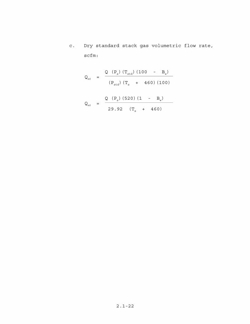
c. Dry standard stack gas volumetric flow rate,
scfm:
Q (Ps)(Tstd)(100 - Bw)Qsd =
(Pstd)(Ts + 460)(100)
Q (Ps)(520)(1 - Bw)Qsd =
29.92 (Ts + 460)


![January 2017 Version 2.1 Coop Negative List for Textile ... und... · January 2017 Version 2.1 Limit Test Method Limit [µg/L] Test Method Limit [mg/kg] Test Method Input Chemicals](https://img.pdfslide.net/doc/110x75/5c86cdca09d3f2815e8cbbf6/january-2017-version-21-coop-negative-list-for-textile-und-january-2017.jpg)