Embed Size (px)
Citation preview
Beteckning:________________
Department of Mathematics, Natural and Computer Sciences
Method for mapping interconnections between
load balanced applications and clustered databases
in a complex server environment
Patrik Jonsson
June 2008
Thesis, 15 points, C level
Computer Science
Computer Science
Supervisor/Examiner: Anders Jackson
Co-examiner: Fredrik Bökman

Acknowledgement
With this thesis I finish my education in Computer Science at the University of Gävle. It has
been a long journey which I haven’t travelled alone. Therefore I wish to extend my gratitude
to following persons, in no order of importance:
I would like to acknowledge my supervisor, Anders Jackson, for his insightful ideas and
patience all the way through.
I would also like to take the opportunity to thank my supervisor at Sandvik IT, Khuong Tran,
for his commitment during my work at Sandvik IT.
I would like to thank Jenny Grannas for continuously pushing me to complete my thesis.
Thank you for your endless support.
Finally I wish to extend my gratitude to Sharon Lazenby, who tricked me into promise that I
would do aerobics in the Boulogne Park until I had finished my thesis. One summer of
aerobics did the trick.
Gävle, May 2011
Patrik Jonsson
Method for mapping interconnections between load balanced
applications and clustered databases in a complex server
environment
by
Patrik Jonsson
Department of Mathematics, Natural and Computer Science
University of Gävle
S-801 76 Gävle, Sweden
Email:
Abstract
A coherent software environment simplifies maintenance - and using the same
terminology facilitates communication and learning within the IT department.
Having a mixed and complex software environment could put strain on the
IT department. Applications and databases needs to be somehow cataloged in case
of system failure. While mapping applications to databases using a unified
terminology might seem to be a good idea from the start, but when it comes to
generating a data model of interconnections based on terminology - confusion will
arise. This confusion could lead to misinterpretations, which in turn could lead to
incidents.
Keywords: interconnections, load balanced, complex, software environment,
application, server, web application, database, cluster
Table of Contents 1 Introduction ....................................................................................................................1
2 Background ....................................................................................................................2
2.1 IT at Sandvik ............................................................................................................2
3 Purpose ...........................................................................................................................2
3.1 Aim ..........................................................................................................................2
3.2 Questions at issue .....................................................................................................3
3.3 Hypothesis ...............................................................................................................3
3.4 Expected result .........................................................................................................4
3.5 Delimitation .............................................................................................................4
4 Method ...........................................................................................................................4
4.1 Earlier research ........................................................................................................4
5 Theoretical framework ....................................................................................................4
5.1 Database clustering methods ....................................................................................4
5.1.1 Microsoft SQL Server 2005 failover ..................................................................4
5.1.2 MySQL v5.0 Replication Master/Slave .............................................................6
5.1.3 Oracle Real Application Cluster 11g .................................................................7
6 Implementation ...............................................................................................................7
6.1 Application architecture ...........................................................................................7
6.1.1 Data model naming conventions ........................................................................7
6.1.2 Database schemas ..............................................................................................8
6.1.3 CRUD ...............................................................................................................8
6.2 User interface ...........................................................................................................8
6.3 Finding the primary entity ........................................................................................8
6.4 Building the logical data model ................................................................................8
6.4.1 Loadbalancer .....................................................................................................8
6.4.2 Microsoft SQL Server 2005 ...............................................................................9
6.4.3 MySQL v5.0 ................................................................................................... 10
6.4.4 Oracle Real Application Cluster 11g ............................................................... 11
6.4.5 Summary ......................................................................................................... 11
6.5 The prototype ......................................................................................................... 12
7 Result ........................................................................................................................... 14
8 Discussion .................................................................................................................... 15
8.1 Critical review ........................................................................................................ 15
8.1.1 Earlier research ............................................................................................... 15
8.1.2 Purpose and aim .............................................................................................. 15
8.1.3 Theoretical framework .................................................................................... 15
8.2 Problems with a uniformed terminology ................................................................. 15
9 Conclusions .................................................................................................................. 15
10 References .................................................................................................................... 16
Appendix a – Dictionary ....................................................................................................... 17
1
1 Introduction Today nearly all large and medium-sized companies have an IT department that support and maintain the
IT infrastructure. To support the day-to-day work, many IT workers use different types of software. There
is software specialized for application distribution and other software for monitoring.
For most medium-sized companies there is no problem to keep the software environment coherent. With
software environment we are referring to the software manufacturers requirements on surrounding
software and/or hardware. In a coherent software environment, the staff can use the same terminology
which facilitates communication and learning within the department. However, when companies expand,
in terms of clients, servers and/or users, it can become difficult to keep the software environment
coherent. Companies can be forced to use a mixture of different environments. Each one of these
environments usually has their own terminology defined by the manufacturer.
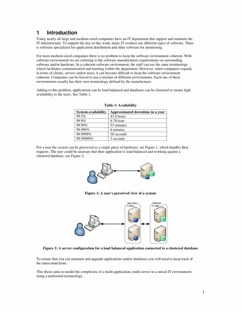
Adding to this problem, applications can be load balanced and databases can be clustered to ensure high
availability to the users. See Table 1.
Table 1: Availability
System availability Approximated downtime in a year
99.5% 43.8 hours
99.9% 8.78 hour
99.99% 53 minutes
99.999% 6 minutes
99.9999% 30 seconds
99.99999% 3 seconds
For a user the system can be perceived as a single piece of hardware, see Figure 1, which handles their
requests. The user could be unaware that their application is load balanced and working against a
clustered database, see Figure 2.
Figure 1: A user's perceived view of a system
Figure 2: A server configuration for a load balanced application connected to a clustered database
To ensure that you can maintain and upgrade applications and/or databases you will need to keep track of
the interconnections.
This thesis aims to model the complexity of a multi-application, multi-server in a mixed IT environment;
using a uniformed terminology.
2
2 Background There are mainly two system types that are vital in a company, business critical and mission critical. For
the business critical systems, availability is the critical component, see Table 1.
Business critical systems like invoicing often use clustered solutions to ensure high availability, in both
application frontend and in their database backend. Given a scenario where you have multiple business
critical systems which could technically be overlapping in hardware, how do you know which systems are
affected by a hardware failure?
Adding to this already rather complex problem, not only hardware failure is problematic in a complex
environment. Upgrades and replacement of existing hardware is also burdensome for involved IT
technicians.
2.1 IT at Sandvik
Sandvik is a global industrial group with advanced products and world-leading positions in selected areas.
During 2007 the Group had 47,000 employees, representation in 130 countries and sales of more than
86,000 million SEK [1].
Sandvik has two IT companies that support every company within the Sandvik Group, Sandvik Software
Development (SSD) and Sandvik IT (SIT). A generalized description of the companies is that: SSD
mainly develop software and SIT maintains the hardware/infrastructure.
Sandvik mainly uses a Windows environment. They utilize a wide range of applications, many of them
in-house developed by SSD. There are both load balanced applications and clustered databases within the
Sandvik domain, see Table 2.
Table 2: Sandvik IT environment in numbers
Sandvik IT-environment (Sweden) in numbers
Servers > 2500
Applications > 400
SQL-clusters > 30
Databases > 1000
Clustered databases > 250
As of now there is an application on SSD that stores information about applications and another
application that stores which database one application is connected to. The database clusters configuration
is currently in a spreadsheet which is only available for database administrators.
Manual handling of information is always unsafe because people make mistakes.
3 Purpose I strive to create an application that can store interconnections between load balanced applications and
clustered applications in a self-explaining data model. A certain level of understanding for relational
databases and Unified Modeling Language (UML) will most likely be required to fully understand the
model.
3.1 Aim
The main aim is to create an accurate database model, with a uniformed terminology, and create a
mapping strategy for storing interconnections between the servers in an environment with load balanced
applications and clustered databases.
3
3.2 Questions at issue
To reach these goals one need to answer following four questions.
Sandvik uses more than one type of clustered database and based on that, the logical conclusion would be
that other companies may do that as well.
• Is it possible to model different clustering types in one data model using a uniformed
terminology?
• Can a simplified data model still be accurate in terms of terminology?
It is commonly known that the IT community uses numerous abbreviations and reuses terms in many
different areas
• Is the terminology on clustering incomparable between different manufacturers?
• Will a simplified data model be understandable or will the semantics be lost?
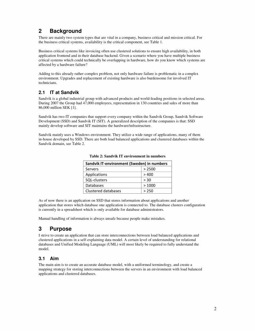
3.3 Hypothesis
A simplified data model with a semantically accurate terminology can solve the problem using; a list
view and a detailed view with related list view.
Using the below Entity-Relationship (ER) model, see Figure 3; one customer has zero to many orders and
one order has zero to many orderlines.
Figure 3: Entity relationship diagram
Combining the hypothesis with the ER model we could create a basic web application as shown below,
see Figure 4.
Figure 4: Basic web application
The first page shows a list of customers. This list of customers is hyperlinked to a second page. This
second page displays detailed information of a selected customer and a list of related orders. These orders
are hyperlinked to a third page. This third page displays detailed information of that order and a list of
related orderlines. Page two and three would in effect look the same.
4
3.4 Expected result
The expected result is that it will be possible to build a prototype web application that can show a
complex environment with only a few numbers of entities (tables).
3.5 Delimitation
The thesis covers will only cover Microsoft SQL Server 2005 (MSSQL), Oracle Real Application Cluster
11g (RAC) and MySQL AB MySQL v5.0 (MySQL). The first two is used at Sandvik and the last is an
open source relational database management system (RDBMS) included for comparison. IBM DB2 has
been excluded due to time constraint.
4 Method The choice of method is literature studies combined with prototyping. A prototype will be constructed so
that users can give instant feedback. The prototype will be based on my reflections during unstructured
interviews with users. Therefore an agile model-driven development (AMDD) [2] method was chosen for
this purpose. The data model will be drawn in UML as recommended by this agile method.
The prototyped web application is to be implemented in C# ASP.NET. This language was chosen since it
is well suited for building prototypes.
4.1 Earlier research
Eight different article databases were searched but no relevant articles about mapping load balanced
applications against clustered databases were found.
A list of the databases searched:
• The ACM Portal
• CiteSeer
• Computer science bibliographies
• Google Scholar
• The collection of Computer Science Bibliographies
• IET Digital Library
• IEEE Xplore
• DOJA - Directory of open access journals
5 Theoretical framework Domain knowledge is important when trying to simplify and/or generalize a concept; because a term can
have a different meaning in a different context. For an object oriented programmer an instance refers to
an object. An object is an instance of a class. But for a MSSQL database administrator, an instance is the
SQL Server application.
5.1 Database clustering methods
5.1.1 Microsoft SQL Server 2005 failover
A failover cluster is two or more nodes that are grouped to form a cluster. A node can have one or more
instances running. Each instance has its own virtual hostname. The nodes has a private network in which
a heartbeat is sent and received, with this heartbeat each node in the cluster can monitor the other nodes.
If the heartbeat is lost, another node can replace the failed node. MSSQL can be configured with different
types of failover clusters, active/passive, active/active and mirroring.
5
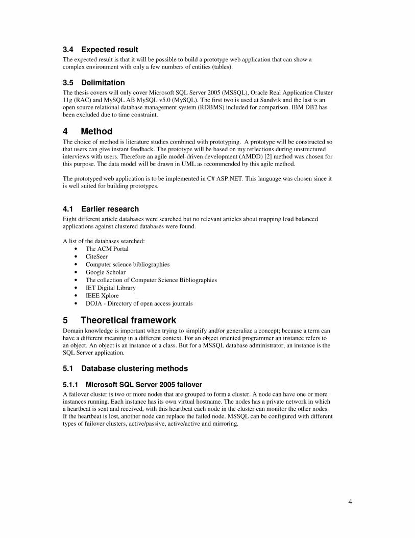
5.1.1.1 Active/Passive configuration
In an active/passive configuration, see Figure 5, the active node contains the instance(s). The passive
node listens to the active nodes heartbeat, if the heartbeat is lost; the passive node becomes active and
recovers the failed instance(s) virtual hostname, which results in traffic to being redirected to from the
failed node to the recovering node. If the former active node comes back online it will take the role of a
passive node.
Figure 5: SQL Server Failover Active/Passive Configuration
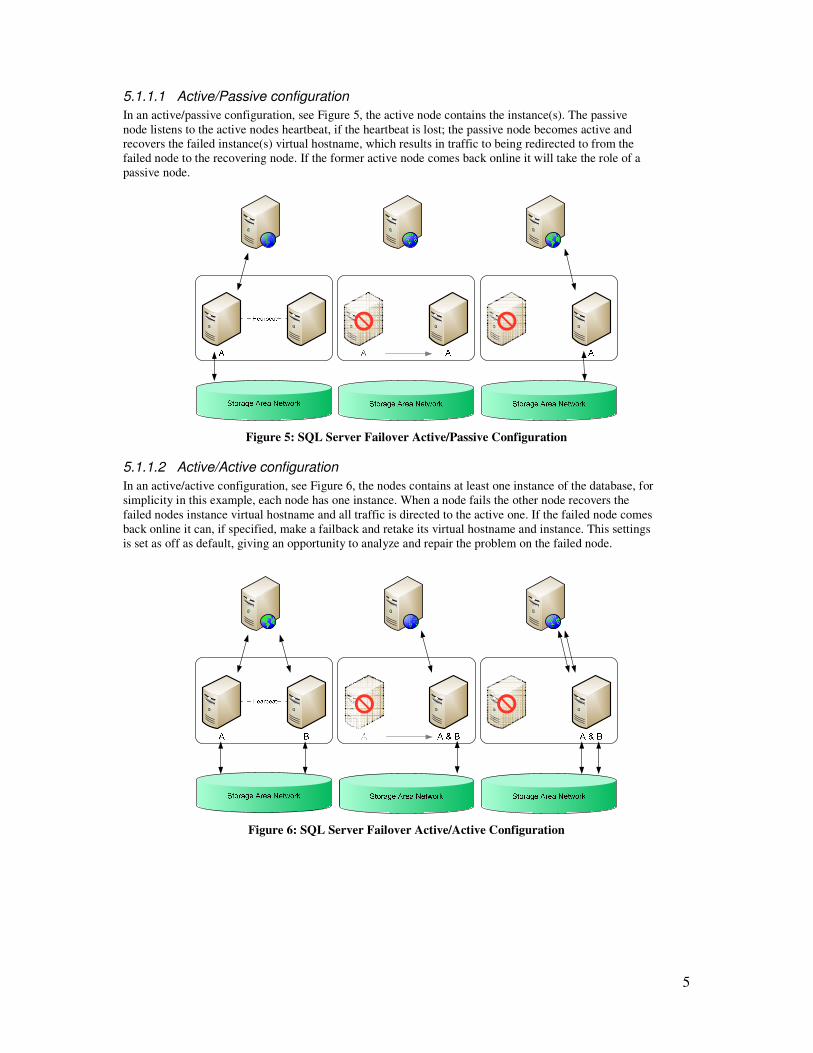
5.1.1.2 Active/Active configuration
In an active/active configuration, see Figure 6, the nodes contains at least one instance of the database, for
simplicity in this example, each node has one instance. When a node fails the other node recovers the
failed nodes instance virtual hostname and all traffic is directed to the active one. If the failed node comes
back online it can, if specified, make a failback and retake its virtual hostname and instance. This settings
is set as off as default, giving an opportunity to analyze and repair the problem on the failed node.
Figure 6: SQL Server Failover Active/Active Configuration
6
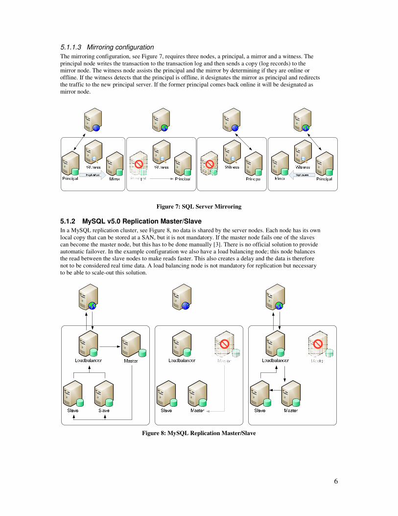
5.1.1.3 Mirroring configuration
The mirroring configuration, see Figure 7, requires three nodes, a principal, a mirror and a witness. The
principal node writes the transaction to the transaction log and then sends a copy (log records) to the
mirror node. The witness node assists the principal and the mirror by determining if they are online or
offline. If the witness detects that the principal is offline, it designates the mirror as principal and redirects
the traffic to the new principal server. If the former principal comes back online it will be designated as
mirror node.
Figure 7: SQL Server Mirroring
5.1.2 MySQL v5.0 Replication Master/Slave
In a MySQL replication cluster, see Figure 8, no data is shared by the server nodes. Each node has its own
local copy that can be stored at a SAN, but it is not mandatory. If the master node fails one of the slaves
can become the master node, but this has to be done manually [3]. There is no official solution to provide
automatic failover. In the example configuration we also have a load balancing node; this node balances
the read between the slave nodes to make reads faster. This also creates a delay and the data is therefore
not to be considered real time data. A load balancing node is not mandatory for replication but necessary
to be able to scale-out this solution.
Figure 8: MySQL Replication Master/Slave
7
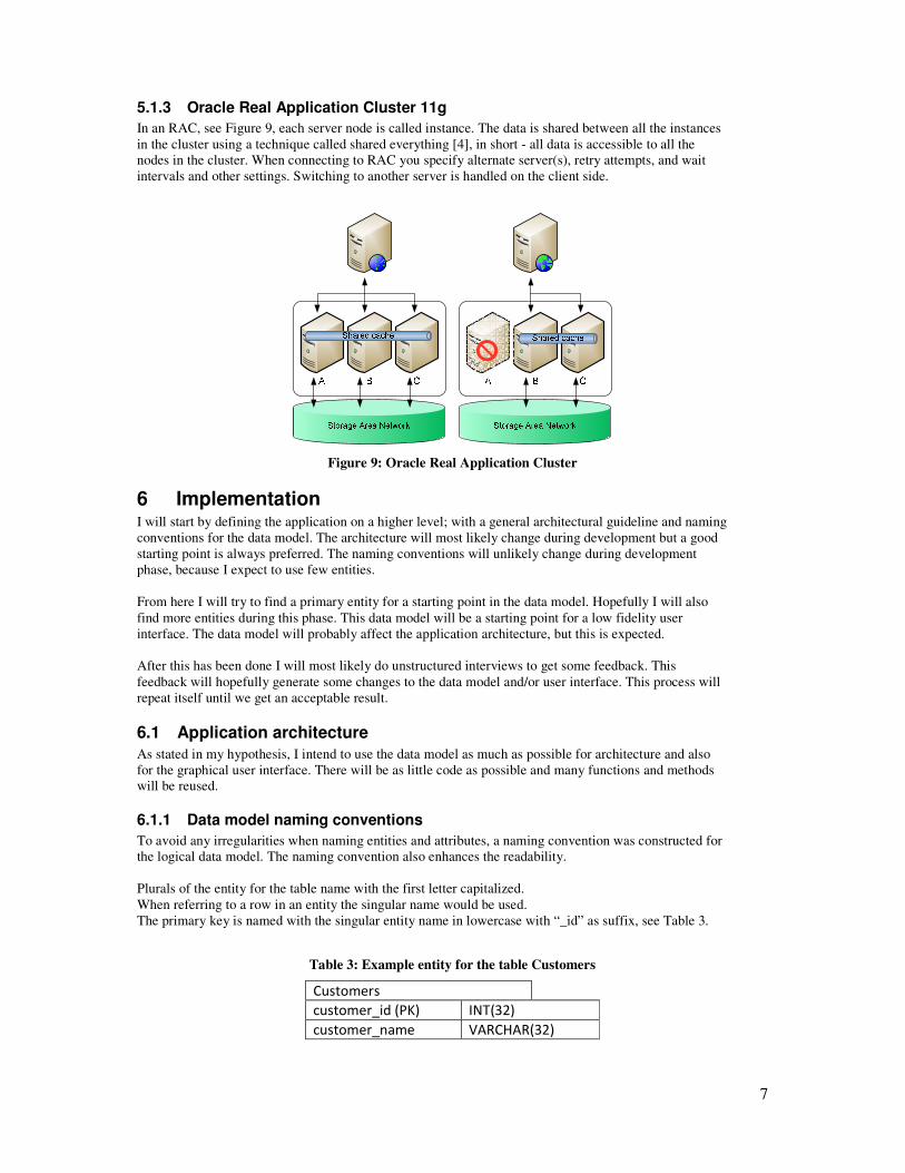
5.1.3 Oracle Real Application Cluster 11g
In an RAC, see Figure 9, each server node is called instance. The data is shared between all the instances
in the cluster using a technique called shared everything [4], in short - all data is accessible to all the
nodes in the cluster. When connecting to RAC you specify alternate server(s), retry attempts, and wait
intervals and other settings. Switching to another server is handled on the client side.
Figure 9: Oracle Real Application Cluster
6 Implementation I will start by defining the application on a higher level; with a general architectural guideline and naming
conventions for the data model. The architecture will most likely change during development but a good
starting point is always preferred. The naming conventions will unlikely change during development
phase, because I expect to use few entities.
From here I will try to find a primary entity for a starting point in the data model. Hopefully I will also
find more entities during this phase. This data model will be a starting point for a low fidelity user
interface. The data model will probably affect the application architecture, but this is expected.
After this has been done I will most likely do unstructured interviews to get some feedback. This
feedback will hopefully generate some changes to the data model and/or user interface. This process will
repeat itself until we get an acceptable result.
6.1 Application architecture
As stated in my hypothesis, I intend to use the data model as much as possible for architecture and also
for the graphical user interface. There will be as little code as possible and many functions and methods
will be reused.
6.1.1 Data model naming conventions
To avoid any irregularities when naming entities and attributes, a naming convention was constructed for
the logical data model. The naming convention also enhances the readability.
Plurals of the entity for the table name with the first letter capitalized.
When referring to a row in an entity the singular name would be used.
The primary key is named with the singular entity name in lowercase with “_id” as suffix, see Table 3.
Table 3: Example entity for the table Customers
Customers
customer_id (PK) INT(32)
customer_name VARCHAR(32)
8
6.1.2 Database schemas
We use database schemas to separate database table entities into groups and to further enhance the
readability of the data model.
6.1.3 CRUD
The prototype web application we use the well-known CRUD-method [5] for accessing data to ensure
data integrity.
6.2 User interface
A simple low-fidelity user-interface was made on a piece of paper which was later transferred to a
mockup model. This mockup-model was later implemented in C# ASP.NET.
6.3 Finding the primary entity
One of the adopted philosophies in the chosen agile method is that “….the simplest solution that covers
all the needs ….” [6], in this case our needs where to construct a simple data model that can store all the
clustering types. Therefore the assumption was made that most of the entities could be bound to a single
primary entity.
To be able to cluster you will need to connect to other computers via a network, so we will use that
knowledge as a connector our data model.
On a network you can find a computer by MAC address (Media Access Control address), IP address
(Internet Protocol address) and hostname.
MAC address was discarded because a virtualized machine can share the same MAC address. Some
machines may have more than one MAC address, one for each network interface card. They are also hard
to remember.
The IP address was discarded because a machine can use dynamic addresses. They are also easy to forget.
The hostname was the best candidate and it was also selected as the primary entity because, each
hostname must be unique in a domain [7].
6.4 Building the logical data model
The hostname entity was the starting point or the data model.
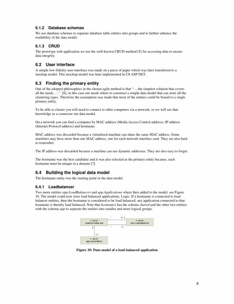
6.4.1 Loadbalancer
Two more entities app.LoadBalancers and app.Applications where then added to the model, see Figure
10. The model could now store load balanced applications. Logic: If a hostname is connected to load
balancer entities, then the hostname is considered to be load balanced, any application connected to that
hostname is thereby load balanced. Note that hostnames has the schema shared and the other two entities
with the schema app to separate the entities into smaller and more logical groups.
Figure 10: Data model of a load balanced application
9
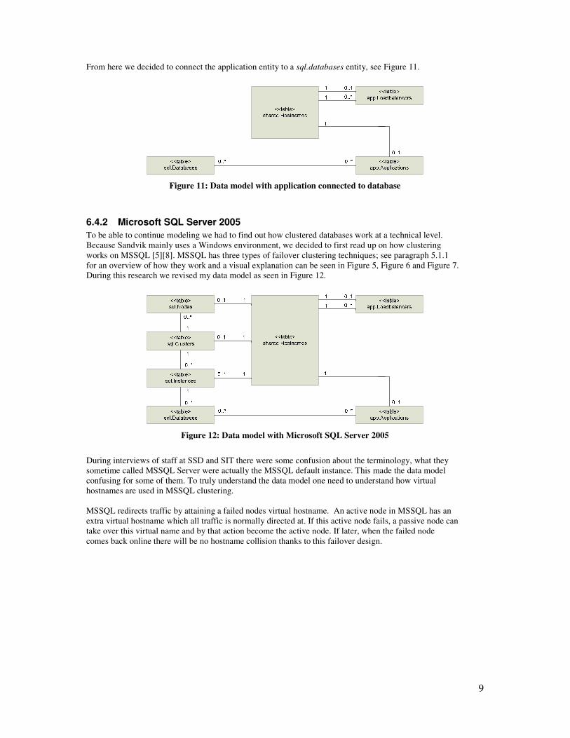
From here we decided to connect the application entity to a sql.databases entity, see Figure 11.
Figure 11: Data model with application connected to database
6.4.2 Microsoft SQL Server 2005
To be able to continue modeling we had to find out how clustered databases work at a technical level.
Because Sandvik mainly uses a Windows environment, we decided to first read up on how clustering
works on MSSQL [5][8]. MSSQL has three types of failover clustering techniques; see paragraph 5.1.1
for an overview of how they work and a visual explanation can be seen in Figure 5, Figure 6 and Figure 7.
During this research we revised my data model as seen in Figure 12.
Figure 12: Data model with Microsoft SQL Server 2005
During interviews of staff at SSD and SIT there were some confusion about the terminology, what they
sometime called MSSQL Server were actually the MSSQL default instance. This made the data model
confusing for some of them. To truly understand the data model one need to understand how virtual
hostnames are used in MSSQL clustering.
MSSQL redirects traffic by attaining a failed nodes virtual hostname. An active node in MSSQL has an
extra virtual hostname which all traffic is normally directed at. If this active node fails, a passive node can
take over this virtual name and by that action become the active node. If later, when the failed node
comes back online there will be no hostname collision thanks to this failover design.
10
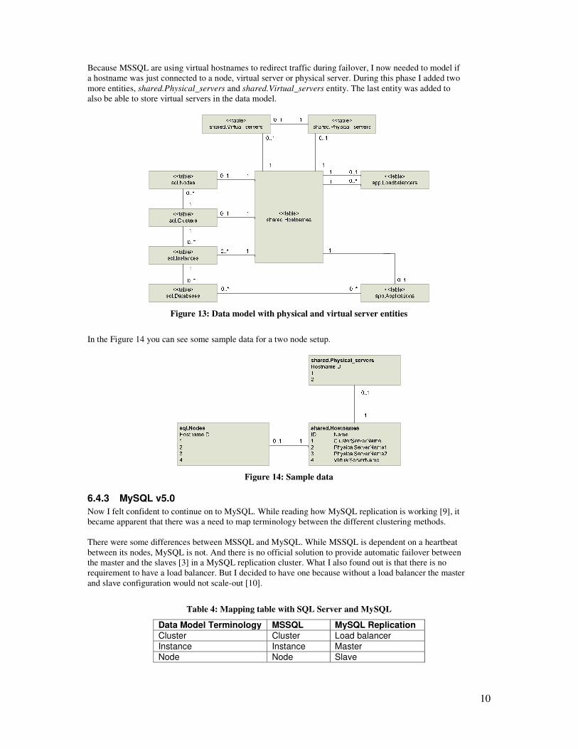
Because MSSQL are using virtual hostnames to redirect traffic during failover, I now needed to model if
a hostname was just connected to a node, virtual server or physical server. During this phase I added two
more entities, shared.Physical_servers and shared.Virtual_servers entity. The last entity was added to
also be able to store virtual servers in the data model.
Figure 13: Data model with physical and virtual server entities
In the Figure 14 you can see some sample data for a two node setup.
Figure 14: Sample data
6.4.3 MySQL v5.0
Now I felt confident to continue on to MySQL. While reading how MySQL replication is working [9], it
became apparent that there was a need to map terminology between the different clustering methods.
There were some differences between MSSQL and MySQL. While MSSQL is dependent on a heartbeat
between its nodes, MySQL is not. And there is no official solution to provide automatic failover between
the master and the slaves [3] in a MySQL replication cluster. What I also found out is that there is no
requirement to have a load balancer. But I decided to have one because without a load balancer the master
and slave configuration would not scale-out [10].
Table 4: Mapping table with SQL Server and MySQL
Data Model Terminology MSSQL MySQL Replication
Cluster Cluster Load balancer
Instance Instance Master
Node Node Slave

11
6.4.4 Oracle Real Application Cluster 11g
From here we went on to RAC. After reading a technical overview [4] and technical comparison between
RAC and Microsoft SQL Server 2005 [11], I came to the conclusion that my hypothesis was rejected.
RAC uses a completely different technical approach to accomplish clustering. This made it impossible to
include RAC into the mapping table, see Table 5, without adding fake data.
Table 5: Mapping table with MSSQL, MySQL and RAC
Data Model Terminology MSSQL MySQL Replication RAC
Cluster Cluster Load balancer -
Instance Instance Master -
Node Node Slave Instance
I you look at the above table you will see that the term instance from an RAC is not at the same level as
the same term from a SQL Server cluster. Also you will notice that the mapping table is missing two
terms for RAC.
The final data model can be seen in Figure 15.
6.4.5 Summary
MSSQL and MySQL hide from the client the fact that they are clustered. The switching from one
database to another occurs on the server side. But to ensure high availability in a RAC you will need to
configure the client to switch during failure.
<<table>
shared.Hostnames
<<table>
shared.Physical_servers
<<table>
shared.Virtual_servers
<<table>
app.Loadbalancers
<<table>
app.Applications
<<table>
sql.Nodes
<<table>
sql.Clusters
<<table>
sql.Instances
<<table>
sql.DBMS
<<table>
sql.Databases
1 1
1
1
1
11 1
1
1
1
1
10..1
0..10..1
0..1
0..1
0..1
0..1
0..*
0..*
0..*
0..*
0..*
0..* 0..*
0..*
Figure 15: Logical Data Model in UML
12
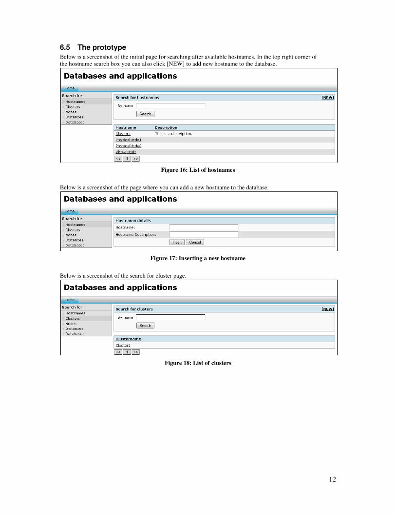
6.5 The prototype
Below is a screenshot of the initial page for searching after available hostnames. In the top right corner of
the hostname search box you can also click [NEW] to add new hostname to the database.
Figure 16: List of hostnames
Below is a screenshot of the page where you can add a new hostname to the database.
Figure 17: Inserting a new hostname
Below is a screenshot of the search for cluster page.
Figure 18: List of clusters
13
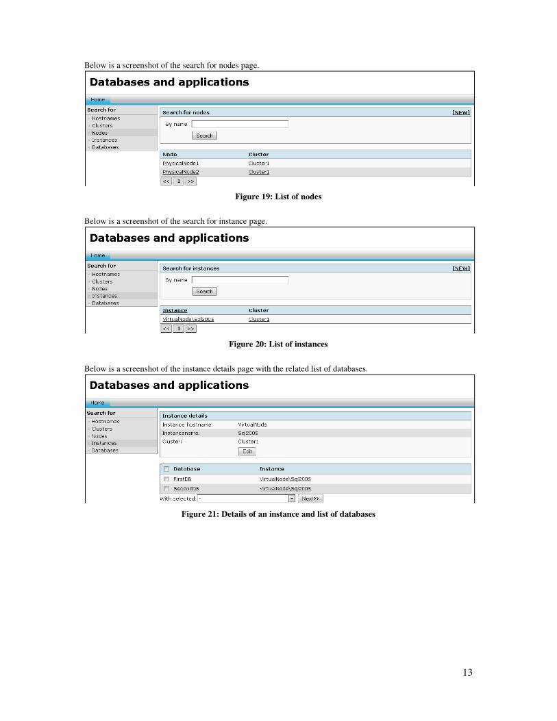
Below is a screenshot of the search for nodes page.
Figure 19: List of nodes
Below is a screenshot of the search for instance page.
Figure 20: List of instances
Below is a screenshot of the instance details page with the related list of databases.
Figure 21: Details of an instance and list of databases
14
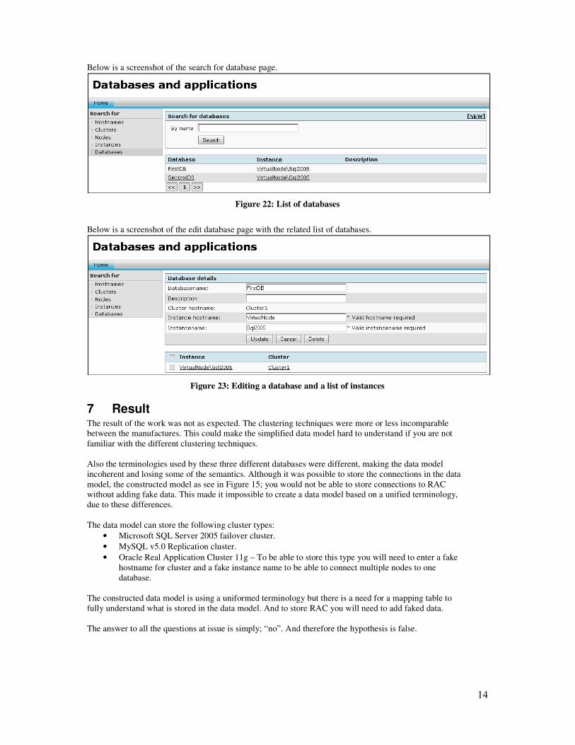
Below is a screenshot of the search for database page.
Figure 22: List of databases
Below is a screenshot of the edit database page with the related list of databases.
Figure 23: Editing a database and a list of instances
7 Result The result of the work was not as expected. The clustering techniques were more or less incomparable
between the manufactures. This could make the simplified data model hard to understand if you are not
familiar with the different clustering techniques.
Also the terminologies used by these three different databases were different, making the data model
incoherent and losing some of the semantics. Although it was possible to store the connections in the data
model, the constructed model as see in Figure 15; you would not be able to store connections to RAC
without adding fake data. This made it impossible to create a data model based on a unified terminology,
due to these differences.
The data model can store the following cluster types:
• Microsoft SQL Server 2005 failover cluster.
• MySQL v5.0 Replication cluster.
• Oracle Real Application Cluster 11g – To be able to store this type you will need to enter a fake
hostname for cluster and a fake instance name to be able to connect multiple nodes to one
database.
The constructed data model is using a uniformed terminology but there is a need for a mapping table to
fully understand what is stored in the data model. And to store RAC you will need to add faked data.
The answer to all the questions at issue is simply; “no”. And therefore the hypothesis is false.
15
8 Discussion The increasing business need for high availability demands a fool proof disaster recovery plan. Any tool
that can support IT removing the complexity in IT environment can be invaluable when lowering the
response time when disaster strikes. The thesis was aimed to find a solution to a complex problem by
applying structure and generalization. The result was rather discouraging when the solution instead could
create a problem when applying a terminology that meant different in different context. Shutting down an
instance in RAC is rather harmless; but by doing the same in MSSQL could unintentionally create data
loss.
8.1 Critical review
Finding what when wrong is crucial in any real world event, because it often generates experience and
hopefully a better of approach when dealing with complexity. We will critically review the thesis and try
to find if we could have chosen a different approach or if we perhaps made a wrong assumption
somewhere down the line.
8.1.1 Earlier research
Searching for earlier research did not turn up any relevant articles. The cause of this could be, that the
subject is too generic, making it difficult to find relevant articles to the subject or that we were using the
wrong keywords. Our initial assumption was that we should use terminology keywords, like high
availability, clustering, load balanced, etc.; this could be a wrong assumptions and perhaps using more
descriptive keywords would have yielded a better result.
8.1.2 Purpose and aim
Using a more narrow purpose, only striving for a connection model for clustered databases and load
balanced application and removing the uniformed terminology requirement could have generated a
different result. The data model might not be readable but the application could work as suggested in the
hypothesis but covering the actual data model.
8.1.3 Theoretical framework
The thesis could have started with a more thorough research of how the different clustered databases were
working and what terminology they were using. Only by looking up the terminology would have falsified
the hypothesis and this thesis would have not been written.
8.2 Problems with a uniformed terminology
To build a unified data model based on terminology seemed to be a good idea at first but ended up being
problematic and possibly dangerous, mainly because the terminology involved in clustering is
semantically different.
This could lead to unexpected results if not all involved are familiar with the technical aspects of
clustering methods and the terminology. If you look at the column for RAC you can see that this
clustering technique only requires a hostname for each instance. The other two names needs to be faked
in order to store the connection it the data model, because all instances in an RAC can access all the data
at the same time, see Figure 9.
A real world example would be the action to shut down an instance.
In context of an RAC this means taking one of the servers in the cluster off line, all the databases will still
be accessible.
In SQL Server context this means shutting down the entire SQL service, all databases will be
inaccessible.
9 Conclusions A data model based on terminology will only be as accurate as the understanding of the terminology and
the knowledge about the different clustering techniques. But even if the data model is imperfect in terms
of terminology - you might rather have something that is searchable instead of a large spread sheet.
16
10 References
Books, reports, articles and websites
[1] Sandvik Group. http://www.sandvik.com (visited 2008-04-10).
[2] W. S. Ambler, The object primer: agile model-driven development with UML 2.0.
Cambridge University Press, Cambridge, 2004.
[3] MySQL AB, 2008. MySQL 5.0 Reference Manual (2008) - 16.3.6. Switching
Masters During Failover. http://dev.mysql.com/doc/refman/5.0/en/replication-
solutions-switch.html (visited 2008-04-14).
[4] B. Lundhild, 2007. Oracle Real Application Clusters 11g: Technical Overview.
http://www.oracle.com/technology/products/database/clustering/pdf/twp_rac11g.p
df (visited 2008-04-15).
[5] P. Bertucci, C. Gallelli and R. Rankins, Microsoft (c) SQL Server 2005 -
Unleashed. SAMS, Indiana, 2007.
[6] K. Beck, Extreme Programming Explained - Embracing Change. Addison
Wesley, Reading, 2000.
[7] M. Stahl, E. Feinler and K. Harrenstien, 1985. Rfc 952. Rfc 952.
http://www.ietf.org/rfc/rfc952.txt (visited 2008-04-13).
[8] A. Hirt, Pro SQL Server 2005 High Availability. Apress, Berkley, 2007.
[9] MySQL AB, 2008. MySQL 5.0 Reference Manual.
http://dev.mysql.com/doc/refman/5.0/en/ (visited 2008-04-14).
[10] MySQL AB, 2008. MySQL Reference Manual (2008) - 16.3.3. Using Replication
for Scale-Out. http://dev.mysql.com/doc/refman/5.0/en/replication-solutions-
scaleout.html (visited 2008-04-14).
[11] P. Newlan, 2007. Oracle Real Applications Clusters 11g: Technical Comparison
with Microsoft SQL Server 2005. Oracle Real Applications Clusters 11g:
Technical Comparison with Microsoft SQL Server 2005.
http://www.oracle.com/technology/products/database/clustering/pdf/twp_rac_com
pare_sqlserver2005_0.pdf (visited 2008-04-13).
[12] TechEncyclopedia.
http://www.techweb.com/encyclopedia/defineterm.jhtml?term=single+point+of+f
ailure (visited 2008-04-16).
[13] Business Dictionary. http://www.businessdictionary.com/definition/mission-
critical.html (visited 2008-04-12).
17
Appendix a – Dictionary
Mission critical systems A system whose failure or disruption in normal business hours will result in the failure of
business operations. For example, for an online business, the communication system is
mission critical; for a steel mill, water and power supply have the same importance [12].
Business critical systems Vital systems (such as production and sales) without which a firm cannot operate or remain
viable. If a critical business system is interrupted, a firm could suffer serious financial, legal,
or other damages or penalties. Correctness and integrity are essential for successful operation
of a business or enterprise.
Single point of failure
Any computer or communications system that contains only one component to do a job
creates a single point of failure. If that single component fails, there is no alternate one to take
its place [13].
Availability Availability is based on probability and statistical analysis.
Load balanced application An application that runs on multiple servers but from the users view appears as one.
Node
A node is a virtual or physical machine.
CRUD The acronym refers to all the major functions that need to be implemented in a relational
database application to consider it complete. The operations are Create, Read, Update and
Delete.
Instance An instance is the process and memory structures running on a node to allow access to the
database.
Database A database is the physical structures residing on a storage device which actually hold the data.
Clustered database A clustered database is a single database that can be accessed by multiple or a single instance.
Cluster group A cluster group is a collection of nodes that owns and maintains the clustered database.
Node type
A nodes function within the cluster group.