Embed Size (px)
Citation preview

DOI: 10.26345/EGRSE-038-17-205X
METHOD OF THE CONTROLLED CURRENT REGULATION – CALCULATION OF PARTIAL
CONSTANTS kAM AND kAN FOR ELLIPTICAL ELECTRODES OF
MICROLATEROLOG
METODA KONTROLOVANÉ REGULACE PROUDU – VÝPOČET DÍLČÍCH KONSTANT
kAM, kAN PRO ELIPTICKÉ ELEKTRODY MIKROLATEROLOGU
František Ryšavý 1
Abstract
It is about micro-well-logging of resistivity in the wall of borehole close to the wall. The well-logging uses the focused electric
current; the current contours penetrate perpendicularly into the borehole wall. The array of the micro-electrodes can be not only circular,
but too elliptical. The current electrode then looks like very thin elliptical/circular contour. The aim of this paper is derivation of formulas
needed for calculation of partial constant denoted as kAM and kAN. This paper explains action of the current electrode formed like ellipsis
on the potential one having its form like an elliptical annulus surrounding the current one. The constant has two components; it presents
the big and small half-axes. The circular electrode array is partial case of the elliptical one. If the only common electrode exists being
simultaneously the potential and current ones, the voltage will be zero.
Abstrakt
Jedná se o karotážní mikroměření měrného elektrického odporu na stěně vrtu v blízkém okolí stěny vrtu. Měření používá fokusaci
elektrického proudu, kdy isolinie proudu vstupují kolmo do stěny vrtu. Mikroelektrodové uspořádání může být nejen kruhové, ale i
eliptické. Proudová elektroda potom vypadá jako eliptická/kruhová křivka. Cílem této práce je odvození vzorců potřebných pro výpočet
dílčí konstanty označené jako kAM a kAN. Tato práce vysvětluje působení proudové elektrody ve tvaru elipsy na potenciálovou elektrodu,
která je tvarovaná jako eliptické mezikruží obklopující proudovou elektrodu. Konstanta má dvě složky; jedná se o hlavní a vedlejší
poloosu. Kruhové uspořádání elektrod je pak dílčím případem eliptického uspořádání. Existuje-li jedna společná elektroda, která je
zároveň potenciální i proudová, má nulové napětí.
Keywords
elliptical array, the current electrode, the potential electrode, ellipsis, annulus, Microlaterolog, well-logging
Klíčová slova
eliptické uspořádání, proudová elektroda, potenciální elektroda, elipsa, mezikruží, Mikrolaterolog, karotáž

- 40 -
1 Introduction If one is going to explain principles of Microlaterolog on basis the method of the controlled current regulation, MARUŠIAK, I. et
al., (1968) and (1969), it has to anticipate derivation of the partial constants like kAM, and kAN are. As electrodes have not cylindrical
surface it is not possible to use the derived formulas of paper RYŠAVÝ, F. (2013), but they must be all newly derived. The electrode array
is presented the current electrode is formed like ellipsis and the potential electrode having form of elliptical annulus. The above system is
concentric.
As each of two mentioned electrodes can change its form from ellipsis to circle there exist four possible combinations: ellipsis and
elliptical annulus, ellipsis and circular annulus, circle and elliptical annulus and, finally, circle and circular annulus. The last one is most
known. All formulas valid for each of combinations can be derived from the basic formula for the first combination. What is important is
the potential electrode is always elliptical/circular annulus and the current electrode presents ellipsis/circle.
Syntax of the method of the controlled current regulation is based on two fundamental formulas. The first solves calculation of the
main constant of the electrode array denoted as K; the second solves calculation of the coefficient of focusing denoted as η. On condition
of regulation that holds UN = UM those formulas have following form:
and11 1
kkKEMAM
.11
11
kk
kk
ENEM
AMAN
All variables are the partial constants labelled with indexes determining the current and potential electrodes. In this paper there are
the partial constants denoted as kAM and kAN. The next constants kEM and kEN are solved in other paper. The central current electrode has
shape as ellipse/circle and is denoted as A, whereas the potential one is elliptical/circular annulus denoted as M or N. The formulas are
identical to those for Laterolog, RYŠAVÝ, F (2013). The detail analyse for Microlaterolog I am going to publish in a next paper. My
present work is oriented only and only to calculation of the partial constants kAM and kAN.
As you will derive the final formulas for elliptical electrode array you are able to receive the formulas for circular electrode array
too. You can only imply condition that both half-axes of ellipsis are equal. So thanks to the elliptical electrode array you can very easy go
over to the circular electrode one. This is a mediated way how to get the final formulas for circular electrodes. The next independent way
is to derive those formulas for circular ones in the direct way. In case you have the final formulas for the circular electrodes the same for
both ways you receive big probability that you have them rightly derived.
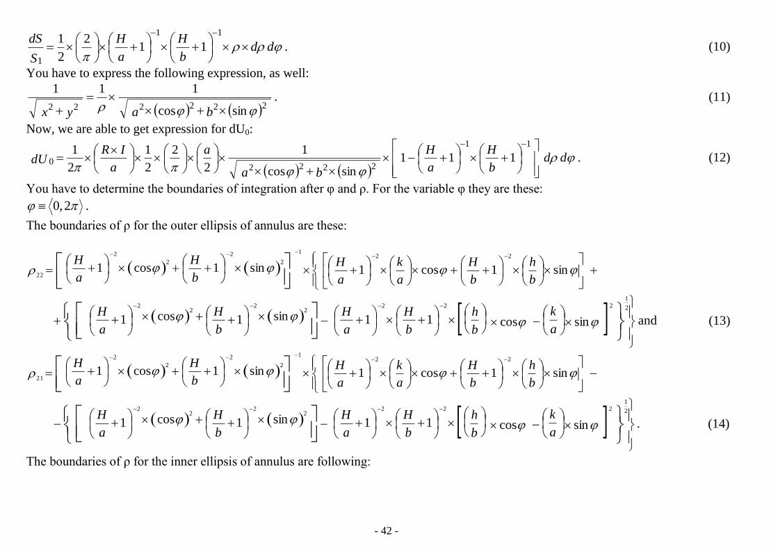
2 Basic metrological characteristics Fig.1 presents the basic metrological characteristics used in this paper. They are these:
A… the shorter half-axis of ellipsis for the current electrode [m],
a… the shorter half-axis of the inner ellipsis of the potential annulus [m],
B…the longer half-axis of ellipsis for the current electrode [m],

- 41 -
b… the longer half-axis of the inner ellipsis of the potential annulus [m] and
H… the potential annulus width [m].
Further, in fig.1 there is denoted the feeding current electrode as A; the potential electrodes are M/N. It presents usual terminology of the
current electrodes in focused well-logging methods. Special case is when holds that A ≡ M.
3 Derivation of the basic formula After fig.1 it is evident you have to start from the potential of elliptical annulus
evoked by an arbitrary point on the surface of the current electrode. This potential
will be denoted as U0.
,1
4
1
1222
120
S
dS
S
dS
yx
IRdUdUdU
(1)
and,2 baS (2)
.111
b
H
a
HbaHbHaS (3)
Equation of the inner ellipsis of annulus is this:
.1
2
2
2
2
b
ky
a
kx (4)
Equation of the outer ellipsis of annulus is following:
.1
2
2
2
2
Hb
ky
Ha
kx (5)
Now, you are to implement the elliptical coordinates:
and,cos ax (6)
.sin by (7)
We are able to express an element of the surface denoted as dS:
.)( ddbadS (8)
Further, we have to write down ratios (dS/S2) and (dS/S1):
and,2
2
1
2
ddS
dS
(9)
x
k
b B
a A
H
h
k
H
h y
A
M/N
Fig.1 Depiction of two Cartesian systems of
variables, (x, y) and (k, h), needed for
describing elliptical array of electrodes
- 42 -
.112
2
111
1
ddb
H
a
H
S
dS
(10)
You have to express the following expression, as well:
.
sincos
111
222222
bayx
(11)
Now, we are able to get expression for dU0:
.111sincos
1
2
2
2
1
2
111
22220
dd
b
H
a
H
ba
a
a
IRdU
(12)
You have to determine the boundaries of integration after φ and ρ. For the variable φ they are these:
.2,0
The boundaries of ρ for the outer ellipsis of annulus are these:
sin1cos1sin1cos1
222
2
2
2 1
22b
h
b
H
a
k
a
H
b
H
a
H
andsincos11sin1cos1
2222
22
2 2
1
a
k
b
h
b
H
a
H
b
H
a
H (13)
sin1cos1sin1cos1
222
2
2
2 1
21b
h
b
H
a
k
a
H
b
H
a
H
.sincos11sin1cos1
2222
22
2 2
1
a
k
b
h
b
H
a
H
b
H
a
H (14)
The boundaries of ρ for the inner ellipsis of annulus are following:

- 43 -
and,sincos1sincos
2
12
a
k
b
h
b
h
a
k (15)
.sincos1sincos
2
11
a
k
b
h
b
h
a
k (16)
The voltage U0 is expressed as follows:
.
sincos11
2
2
2
1
2
1
sincos2
2
2
1
2
1
2
02222
11
2
02222
0
22
21
12
11
ba
dd
b
H
a
Ha
a
IR
ba
dda
a
IRU
(17)
We integrate after ρ. In such case you will get the following expression:
sincos1sincos2
2
2
12
2
1
2
0
2222 2
1
0 a
k
b
hba
a
a
IRU
2
0
2222 2
111
sincos112
2
2
1ba
b
H
a
Ha
a
IR
sin1cos1sin1cos12
2
2
2
22
22
1
b
H
a
H
b
H
a
H
.sincos11
2222
1
da
k
b
h
b
H
a
H
(18)
Integrals in question are two; the less and the more complicated. At first we are to solve the more complicated one needed for counting of
both integrals, because the less complicated one is only partial case of the more complicated:

- 44 -
da
k
b
h
b
H
a
H
b
H
a
H
b
H
a
Hba
sincos11sin1cos1
sin1cos1sincos
2222
22
2 2
1
22
22
12
0
2222 2
1
da
k
b
h
b
H
a
H
b
H
a
H
b
H
a
Hba
sincos11sin1cos1
sin1cos1sincos2
2222
22
2 2
1
22
22
12
0
2222 2
1
.cossin11cos1sin1
cos1sin1cossin2
2222
22
2 2
1
22
22
12
0
2222 2
1
da
k
b
h
b
H
a
H
b
H
a
H
b
H
a
Hba
(19)
We implement substitution tg (φ/2) = t and both integrals solve with the help of the complex variable. The result is that:
da
k
b
h
b
H
a
H
b
H
a
H
b
H
a
Hba
sincos11sin1cos1
sin1cos1sincos
2222
22
2 2
1
22
22
12
0
2222 2
1

- 45 -
.1111
1111
26
2222
b
h
b
H
a
H
aa
k
a
H
b
H
b
(20)
If you install condition into formula (20) that H = 0, you will be able to express the less complicated integral needed for counting U0:
.11
11
26sincos1sincos
222
2
1
2
0
2222 2
1
b
h
aa
k
bda
k
b
h
ba
(21)
Now, you can determine U0:
.11111132
1
1132
1
221221
22
0
b
h
b
H
b
H
a
k
a
H
a
H
b
a
a
IR
b
h
a
k
b
a
a
IRU
(22)
We have to determine an element of voltage denoted as dU for the system of new Cartesian coordinates (k, h).
.0S
dSUdU (23)
For the surface of ellipsis it holds that:
.BAS (24)
Applying new elliptical coordinates you will obtain expression for dS:
. ddBAdS (25)
and,cos Ak (26)
.sin Bh (27)
Now, you can express ratio dS/S:
.2
2
1
dd
S
dS
(28)
The boundaries of integration for ρ are these: ρ ≡ < 0, 1>; for φ there hold the boundaries: φ ≡ < 0, 2π >. We can define expression
for voltage U:
- 46 -
.sin1112
2
13
2
1
cos1112
2
13
2
1
sin12
2
13
2
1
cos12
2
13
2
1
2
0
1
0
22
221
2
0
1
0
22
221
2
0
1
0
222
2
0
1
0
222
ddb
H
b
B
b
H
a
IR
dda
H
a
A
a
H
b
a
a
IR
ddb
B
a
IR
dda
A
b
a
a
IRU
(29)
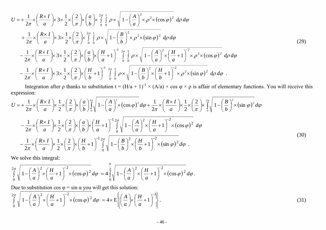
Integration after ρ thanks to substitution t = (H/a + 1)-1
× (A/a) × cos φ × ρ is affair of elementary functions. You will receive this
expression:
db
B
a
IRd
a
A
b
a
a
IRU
2
0
2
22
0
2
2
sin12
2
1
2
1cos1
2
2
1
2
1
.sin1112
2
1
2
1
cos1112
2
1
2
1
2
0
2221
2
0
2221
db
H
b
B
b
H
a
IR
da
H
a
A
a
H
b
a
a
IR
(30)
We solve this integral:
.cos114cos112
0
2222
0
222
da
H
a
Ad
a
H
a
A
Due to substitution cos φ = sin α you will get this solution:
.1E4cos11
12
0
222
a
H
a
Ad
a
H
a
A
(31)

- 47 -
With the help of condition that H = 0 you receive the next integral:
.E4cos12
0
22
a
Ad
a
A
(32)
The next integral is again elliptical one:
.1E4sin114sin11
12
0
2222
0
222
b
H
b
Bd
b
H
b
Bd
b
H
b
B
(33)
And again with the help of condition that H = 0 you attain that:
.E4sin12
0
22
b
Bd
b
B
(34)
Finally, we obtain the formula for voltage U:
.1E1E2
21E1E2
22
11111
b
H
b
B
b
H
b
B
a
H
a
A
a
H
a
A
b
a
a
IRU
(35)
We can now define the formula for the partial constants kAM and kAN:
,2
21 FFa
k
(36)
andaAfor,1E1E2
2
11
1
a
H
a
A
a
H
a
A
b
aF
(37)
.bBfor1E1E2
2
11
2
b
H
b
B
b
H
b
BF
(38)
4 Analysis of the derived formulas This chapter is about optimal dimensions of both electrodes. From formulas (37) and (38) there result out these inequalities:
- 48 -
and,11;11
1
a
H
a
H
a
A
.11;11
1
b
H
b
H
b
B
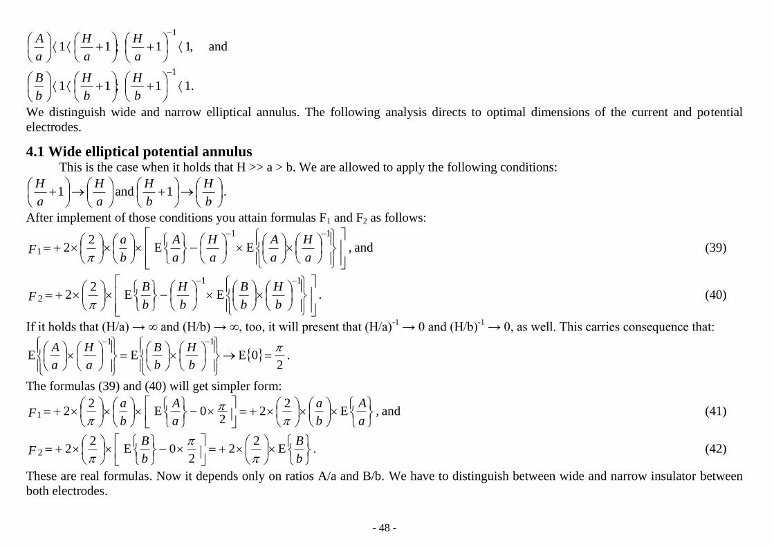
We distinguish wide and narrow elliptical annulus. The following analysis directs to optimal dimensions of the current and potential
electrodes.
4.1 Wide elliptical potential annulus This is the case when it holds that H >> a > b. We are allowed to apply the following conditions:
.1and1
b
H
b
H
a
H
a
H
After implement of those conditions you attain formulas F1 and F2 as follows:
and,EE2
2
11
1
a
H
a
A
a
H
a
A
b
aF
(39)
.EE2
2
11
2
b
H
b
B
b
H
b
BF
(40)
If it holds that (H/a) → ∞ and (H/b) → ∞, too, it will present that (H/a)-1
→ 0 and (H/b)-1
→ 0, as well. This carries consequence that:
.2
0EEE
11
b
H
b
B
a
H
a
A
The formulas (39) and (40) will get simpler form:
and,E2
22
0E2
21
a
A
b
a
a
A
b
aF
(41)
.E2
22
0E2
22
b
B
b
BF
(42)
These are real formulas. Now it depends only on ratios A/a and B/b. We have to distinguish between wide and narrow insulator between
both electrodes.
- 49 -
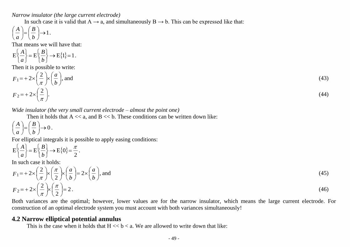
Narrow insulator (the large current electrode)
In such case it is valid that A → a, and simultaneously B → b. This can be expressed like that:
.1
b
B
a
A
That means we will have that:
.11EEE
b
B
a
A
Then it is possible to write:
and,2
21
b
aF
(43)
.2
22
F (44)
Wide insulator (the very small current electrode – almost the point one)
Then it holds that A << a, and B << b. These conditions can be written down like:
.0
b
B
a
A
For elliptical integrals it is possible to apply easing conditions:
.2
0EEE
b
B
a
A
In such case it holds:
and,22
221
b
a
b
aF
(45)
.22
222
F (46)
Both variances are the optimal; however, lower values are for the narrow insulator, which means the large current electrode. For
construction of an optimal electrode system you must account with both variances simultaneously!
4.2 Narrow elliptical potential annulus This is the case when it holds that H << b < a. We are allowed to write down that like:

- 50 -
.11and11
b
H
a
H
The result is that:
and,0EE2
21
a
A
a
A
b
aF
(47)
.0EE2
22
b
B
b
BF
(48)
The consequence of that is that (F1 + F2) = 0. That means (k/a) → ∞. It holds that k → ∞ and k-1
→ 0. The result is U → 0. This
variant is not at all convenient for construction of the potential electrode. Here bigness of current electrode does not play a role.
5 Analysis after the shape of electrode array determined by ratio (a/b) Next theorizations can be done from the point of view how looks ratio (a/b). We distinguish two all different extremal cases. The
first is when it is a circular electrode array, the second holds for a stretched elliptical electrode array. The second one can tend to the
electrode pad of Proximity Log.
For a = b you have (a/b) =1what presents rather circular annulus, whereas, for a ‹‹ b is (a/b) →0 and it is much stretched elliptical
annulus. Let’s return again to formulas derived for narrow and wide insulators.
For narrow insulator between current and potential electrodes the current one fills almost all inner surface of annulus. The potential
annulus is wide. Formulas (43) and (44) are:
and,2
21
b
aF
.
222
F
The wide insulator reflects situation when the current electrode is very small tending to the point/abscissa. The potential annulus
remains again wide. Formulas (45) and (46) are these:
and,22
221
b
a
b
aF
.2
2
222
F
The first extremal case holds for circular electrode array. In such case you have to imply condition that (a/b) =1.
Circular electrode array; (a/b) =1. For narrow insulator holds the following expressions:

- 51 -
and,2
21
F .
222
F For their sum you receive that .
2421
FF
For wide insulator you will get these formulas:
and,21 F .22 F The sum is following: .421 FF
The sum of functions F1 and F2 is nonzero in both cases. For the narrow insulator is even lower than for the wide one. For an ideal
array should be respected both conditions simultaneously. Such ideal array is the pointed current electrode fills almost all the inner surface
of the potential electrode formed as a wide annulus.
The second extremal case tends to an infinitely-long linear electrode array. Here holds condition that (a/b) →0.
Stretched elliptical electrode array (an elliptical electrode system with high eccentricity); (a/b) →0.
For narrow insulator you have these formulas:
and,01F .2
22
F Their sum is following: .
2221
FF
For wide insulator you obtain such formulas:
and,01F .22 F For their sum holds that .221 FF
The sum of functions F1 and F2 is again nonzero in both cases, but value is half in comparison to circular electrode array. Conditions
for narrow and wide insulators must be again respected simultaneously. An ideal electrode array is the thin and much stretched elliptical
current electrode fills almost inner surface of the potential electrode having form of wide and stretched elliptical annulus. The current
electrode can even look as a thin metallic abscissa. Such electrode array can be replaced with rectangular electrodes being easier for
manufacturing.
6 Control – deduction of formula for circular electrodes We apply conditions that B = A and b = a. Then we receive this formula:
.1E1E2
4
11
21
a
H
a
A
a
H
a
AFF
(49)
Now, the variables denoted as A, a, present radiuses of circles. We have to use identities: a = (d/2) and A = (D/2) where d and D are
diameters.
.2
221 FFd
k

- 52 -
The constant 2 must be transposed into denominator of the fracture being on the right side of equation.
.12
E12
E2
82
11
21
d
H
d
D
d
H
d
DFFF
(50)
where D…the diameter of the circular current electrode [m] and
d…the inner diameter of the potential current annulus [m].
The formula holds for D < d. This is formula derived for the circular electrode array. It is partial case of the elliptical one. As I
made, for my own control, the direct way of derivation of final formula for circular electrodes too, I can say the formula is derived rightly.
Consequence of that is both formulas for circular and elliptical electrodes are rightly derived.
7 The special case of the common potential and current electrodes; A ≡ M In such case holds that U = 0. If two electrodes are identical then their potentials are identical too. It results in that difference
between both potentials presenting voltage U equals to zero. An analytical way is following. You have to implement conditions into
formulas (37) and (38) that: a = A and b = B; further, H = 0. In such case it holds that:
.0112
21E1E2
2and,0112
21E1E2
2 21
b
aF
b
a
b
aF
As F1 = 0 and F2 = 0 too consequence of that is (F1 + F2) = 0; constant k is equal to infinity and 0k1
AM
. So in such case like that holds
again it is a thing of geometry, in the first instance zero distance between both electrodes; result of that is U = 0. It is for both elliptical
and circular electrodes. This property can bet easier counting of the main constant of Microlaterolog.
8 Conclusions This analysis of the derived formulas confirms the following conclusions:
The derived constant for elliptical electrodes can be used for counting of partial constants kAM and kAN; characteristics of the electrode
system are well-measurable and so it is possible constants exactly to count.
It is possible to get the final formula for the circular electrodes too, thanks to implication of condition equality for both half-axes
ellipses.
The surface of the potential electrode ought to be as big as possible, whereas, the surface of the current electrode as small as possible,
but simultaneously covering almost all the inner surface of potential annulus. Between the current and potential electrodes is only thin
but also functional insulator. The voltage will be nonzero and high.

- 53 -
If it is that holds that A ≡ M, the voltage of the annulus electrode is zero and the partial constant tends to infinity. Consequence of that is
the reciprocal value of the partial constant is equal to zero; ;0k 1AM the effect is independent on the electrode shape.
References
MARUŠIAK, I. Princip kontrolirovannoj reguljacii toka mnogoelektrodnych karotažnych zondov. 1. část, Užitá geofyzika, 7, Brno, 1968
MARUŠIAK, I., TĚŽKÝ, A., JONÁŠOVÁ, V. Princip kontrolirovannoj reguljacii toka mnogoelektrodnych karotažnych zondov. 2. část, Užitá geofyzika, 8,
Brno, 1969
RYŠAVÝ, F. Method of the controlled current regulation – calculation of partial constants for cylindrical electrodes, EGRSE Journal, vol. XX, no. 2, 2013, p.
86 – 103
RYŠAVÝ, F. Method of the controlled current regulation – Laterolog, EGRSE Journal, vol. XX, no. 2, 2013, p.67 - 85
Author 1 RNDr. František Ryšavý, Lesní 3, 695 03 Hodonín, Czech Republic, [email protected]