Embed Size (px)
Citation preview

____________________________________________________________________________________________________________________ ASN FO Sub Cable Installation PiPiper 2014 June 4 - Page 1 of 19 Alcatel-Lucent Submarine Networks. Confidential – Use Pursuant to Company Instruction
METHOD STATEMENT for PIPIPER
SUBMARINE FIBRE OPTIC COMMUNICATIONS CABLE
SURVEY & INSTALLATION WORKS FROM HWM TO 12 NM
The marine operations required to install the systems include:
x Cable Route Survey
x Route Clearance
x Pre-Lay Grapnel Run
x Cable Surface Lay
x Cable Burial
x Landing
x Crossings engineering
x Post Lay Inspection and Burial
Cable Route Survey
The marine cable route survey is performed to define a cable routing that will maximise cable survivability for acceptable system and component cost.
The route selected determines cable length and cable design (factors that the cable manufacturer must understand), and establishes the methods to be followed for cable deployment. The survey also generates a reference record that supports subsequent maintenance and repair of the cable.
In water of depths less than 1000m, swath bathymetry, side scan sonar, seismic profiling and a geotechnical survey will be performed. The nominal corridor to be surveyed is 500m wide, which allows adjustment of the cable location if unfavourable conditions are found later. The final installed cable will lie within the survey corridor.
In water of depths greater than 1000m, multibeam bathymetry only will be acquired.
It is common practice to bury the cable to a depth of about 1 meter in the sea bed in shallow water sections (i.e. between 1000m and 15m of water depth), to protect it from hazards such as fishing trawls.

____________________________________________________________________________________________________________________ ASN FO Sub Cable Installation PiPiper 2014 June 4 - Page 2 of 19 Alcatel-Lucent Submarine Networks. Confidential – Use Pursuant to Company Instruction
Burial is done only where conditions allow - (e.g. in sandy and muddy sediments). Cable route survey therefore incorporates burial assessment survey, which tests the mechanical properties of the seabed along the route. Sediments are investigated by hydroacoustic means (side scan sonar and sub-bottom profiler), and by intermittent physical samples (grab samples or cone penetrometer tests).
Where plough burial of the cable is needed, surveys assist in the identification of routes that avoid hydrothermal vents, seeps, areas of tectonic activity, seamounts, canyons and dissected terrain, shallow water coral reefs and deep or cold water reefs, all of which are unfavourable environments in which to attempt to bury cable (i.e. plough burial is not practicable on these substrates).
Inshore cable route survey (0-15m water depth) is conducted using small boats and divers to perform visual checks of the seabed and map the ideal route for the cable as it approaches the shore. The inshore survey is normally conducted along a corridor about 200m wide, in order to provide flexibility to adjust the cable routing to avoid hazards and minimise threats to marine habitats.
If necessary the inshore survey may incorporate video footage or mapping of important ecological zones, habitats and features on the approach to shore, to ensure that they will not be damaged, or to support planning of mitigating and compensating measures for unavoidable impacts.
Surveys (in conjunction with desk top studies and local consultations) highlight the existence of other important coastal and littoral ecological complexes such as sea grass, mangrove and dune formations, and important features such as marine and coastal conservation areas, nesting sites and migratory routes.
The studies that precede cable laying serve to lower the probability of ecological impacts, since in large part they are intended to identify routes for the buried cable that will avoid seamounts, volcanoes, canyons, vents, seeps, deepwater reefs, carbonate mounds, and dissected terrain – all areas that present problems for plough deployment, but which also are often associated with above-average biodiversity and biological value.
Installation Vessels
ASN’s complement of vessels includes 140-meter cable ships, which have been designed as powerful integrated cable installation vessels.
All vessels conform to MARPOL , including general requirements over the control of waste oil, engine oil discharges and grey and black waste water discharges; prevention of pollution

____________________________________________________________________________________________________________________ ASN FO Sub Cable Installation PiPiper 2014 June 4 - Page 3 of 19 Alcatel-Lucent Submarine Networks. Confidential – Use Pursuant to Company Instruction
by garbage from ships and prevention of air pollution; and maintain operating procedures for dealing with incidents such as oil and waste spillages that potentially may threaten the marine environment. One of the cable ships is accredited by the European Maritime Safety Agency to perform maritime environmental protection activities.
The vessel does not require the use of its anchors to assist in any of the cable installation operations – cable laying, ploughing and shore end landings are all performed using dynamic positioning mode. The installation vessels can produce a high bollard pull (up to 130 tonnes) for ploughing, which is essential for achievement of target burial depths for submarine cable systems. Vessels are entirely self-sufficient throughout all cable installation operations.
Route Clearance (RC)
RC is performed to clear the cable path of obstacles such as out of service (OOS) cables identified during the cable route survey, as these can be hazardous to both the vessel’s
____________________________________________________________________________________________________________________ ASN FO Sub Cable Installation PiPiper 2014 June 4 - Page 4 of 19 Alcatel-Lucent Submarine Networks. Confidential – Use Pursuant to Company Instruction
installation equipment and the cable itself. RC is only carried out in areas where burial is deemed necessary. RC excludes all works associated with ordnance, radio-active, or other hazardous materials.
The Desk Top Study and the Marine Route Survey will establish positions of OOS cables that may need to be removed from the proposed routes.
OOS cable sections are normally removed so as to clear a 500m corridor either side of the centreline of the route. The cable ends will be left on the seabed.
RC is conducted using the same high navigational accuracy as used in the main lay operations. Any recovered cable will be landed for proper disposal at suitably equipped locations. Recovered repeaters, if any, will also be landed and disposed of according to standard procedures.
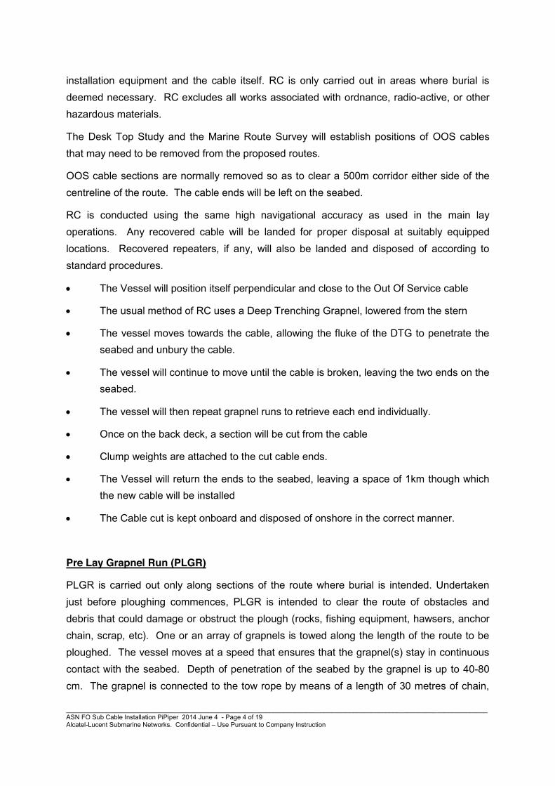
x The Vessel will position itself perpendicular and close to the Out Of Service cable
x The usual method of RC uses a Deep Trenching Grapnel, lowered from the stern
x The vessel moves towards the cable, allowing the fluke of the DTG to penetrate the seabed and unbury the cable.
x The vessel will continue to move until the cable is broken, leaving the two ends on the seabed.
x The vessel will then repeat grapnel runs to retrieve each end individually.
x Once on the back deck, a section will be cut from the cable
x Clump weights are attached to the cut cable ends.
x The Vessel will return the ends to the seabed, leaving a space of 1km though which the new cable will be installed
x The Cable cut is kept onboard and disposed of onshore in the correct manner.
Pre Lay Grapnel Run (PLGR)
PLGR is carried out only along sections of the route where burial is intended. Undertaken just before ploughing commences, PLGR is intended to clear the route of obstacles and debris that could damage or obstruct the plough (rocks, fishing equipment, hawsers, anchor chain, scrap, etc). One or an array of grapnels is towed along the length of the route to be ploughed. The vessel moves at a speed that ensures that the grapnel(s) stay in continuous contact with the seabed. Depth of penetration of the seabed by the grapnel is up to 40-80 cm. The grapnel is connected to the tow rope by means of a length of 30 metres of chain,

____________________________________________________________________________________________________________________ ASN FO Sub Cable Installation PiPiper 2014 June 4 - Page 5 of 19 Alcatel-Lucent Submarine Networks. Confidential – Use Pursuant to Company Instruction
with a similar length of chain following the grapnel; the chain further assists in keeping the grapnel in contact with the seabed. The forward motion and design of the Grapnels creates a clear path by hooking any linear obstacle. The grapnels are retrieved to the vessels deck at least every 20km, or when a large tension is registered by the vessel, as this will indicate that an unidentified obstacle has been hooked. All retrieved debris are kept on board for further safe disposal at port.
PLGR excludes all works associated with ordnance, radio-active, or other hazardous materials.
PLGR operations would normally be carried out by a specially mobilised and fitted out vessel capable of sustaining good slow speed positional control with good bollard pull capability. The vessel would have sufficient deck space to mount a simple winch, simple guides and a stern roller to deploy the grapnel(s) and stow any recovered debris. Alternatively, depending on operational logistics and on the information obtained from the surveys, the PLGR operation may be performed by the main lay vessel.
The PLGR vessel navigates along the route using the same position fixing systems as employed by the main lay vessel – GPS. The route followed by the PLGR is maintained as close as practicable to the selected ploughing route and is always maintained within the swathe of the route surveyed during route selection.
As the vessel moves along the route the towing tension is monitored and the grapnel(s) is recovered if the tension increases indicating that an obstruction has been hooked. As a matter of routine grapnels are recovered and inspected at minimum intervals of 15km along the route. Usually a single tow is made along the route but in areas where other marine activity or debris amounts are high, additional runs may be made.
Cable laying - surface laying
In water depths exceeding 1000m the cable will be laid on the surface of the sea-bed.

____________________________________________________________________________________________________________________ ASN FO Sub Cable Installation PiPiper 2014 June 4 - Page 6 of 19 Alcatel-Lucent Submarine Networks. Confidential – Use Pursuant to Company Instruction
Cable Laying – plough burial of cable
Plough burial of cable is usually performed in water depths of less than 1000m where the seabed conditions allow.
An industry-standard cable plough weighs approximately 12 tonnes in water. It is deployed from the stern of the installation vessel and towed behind the ship, burying the cable into the seabed, usually to a depth of 1 m, as it progresses along the route.
As the plough is towed through the seabed its share blade and inclined cutting disk lift a wedge of substrate. As the plough progresses forwards, this sediment is dropped back into the trench, emplacing the cable at the bottom of a relatively undisturbed sediment wedge.
Plough share cuts wedge of sea bed substrate
Wedge displaced; cable positioned in trench
Plough passes, wedge replaced over cable

____________________________________________________________________________________________________________________ ASN FO Sub Cable Installation PiPiper 2014 June 4 - Page 7 of 19 Alcatel-Lucent Submarine Networks. Confidential – Use Pursuant to Company Instruction
A combination of specialist cable lay software and DGPS control the position of the ship and plough to achieve accurate cable positioning, using thrusters and propellers and with no need for anchors.
Plough burial achieves a maximum burial depth of 2m (depending on seabed type). The width of the trench is 0.2m (the width of the plough share). The plough will not be deployed in areas where steep or side slopes prevent it, or where the route crosses an in-service cable or pipeline.
Following plough burial of the cable a ca 4m strip footprint coincident with the passing of the plough (width of the plough share incision, plus the tracks of the skids and stabilisers), remains visible for a period that will vary depending on nature of the substrate and local seabed hydrodynamics and sedimentation.
In certain demanding environments where there is a soft sea bead and/or high intensity shipping activity that poses an elevated threat to the cable, deep burial requirements may be stipulated. For example in Singapore port limits, cables must be buried to a depth of 10m in the seabed. Such deep burial is achievable with specialised jetting and rock cutting equipment
Shore-end Landing – Direct Landing Method Statement
Where possible cables are brought to shore directly from the main-lay cable ship (where this is not possible a “separate” shore end is required). Such shore-end operations are usually completed within one day.
Operational planning

____________________________________________________________________________________________________________________ ASN FO Sub Cable Installation PiPiper 2014 June 4 - Page 8 of 19 Alcatel-Lucent Submarine Networks. Confidential – Use Pursuant to Company Instruction
Preparations for the operation are often made the previous day. Various resources and pre-requisites are assembled:
x Subcontract plant hire
x Beach access arrangements for heavy plant and Local Authority agreement.
x Permits for the cable installation on the fore-shore.
x Route planning to avoid of ‘altercourses’ in the ‘pull-in’.
x If ‘altercourses’ exist, what methods are to be used to secure the cable.
x Design of post installation cable protection.
x Commissioning of divers and support facilities.
Execution
Prior to the cable landing operation, divers will place a marker buoy at the inner limit of the cable laid by the Cable Vessel. This marks the start position of the proposed shore end route. Divers may identify gullies / slopes along the route centre line, through which the cable can be routed, and will again mark their position(s) using marker buoys.
During the shore end landing operation the Cable Vessel will position itself as close as reasonably practicable to the first marker buoy.
The laying vessel will approach the shore to the agreed cable launching position, or to the limit deemed acceptable by the Master and maintain this position by use of its dynamic positioning technology. Once the vessel has achieve a stable station keeping condition the cable floated off the stern of the vessel and pulled into the beach using a winch or tractor. This will enable the cable to be initially aligned as close as possible to the target route selected by the divers. During the pull-in operation, additional slack cable (approx 10m to 15m) will be pulled inshore of the anchor points installed by the divers.

____________________________________________________________________________________________________________________ ASN FO Sub Cable Installation PiPiper 2014 June 4 - Page 9 of 19 Alcatel-Lucent Submarine Networks. Confidential – Use Pursuant to Company Instruction
Cable being floated ashore viewed from the vessel stern
The pull can be provided by one of three methods:
x a separate work-boat to haul the cable end.
x a hauling line which, is passed around a sheave placed on the beach, and then returned to the laying vessel which provides the hauling tension itself.
x most commonly, a hauling line which is passed around a beach sheave but which is hauled by means of beach equipment e.g. a tractor hauler.
A heavy excavator will be used as “anchor point” for quadrant. The quadrant will allow the pulling rope and cable to be pulled along the beach in a 90 degree angle from the direction of landing. Normal beach pulling will require one excavator to pull the rope attached to the cable for a distance of 100-200 m along the beach.
Cable/rope will be secured every time the excavator will have to go back to perform a new pull. These beach pulls will continue until all the required cable is safely landed on the beach.
____________________________________________________________________________________________________________________ ASN FO Sub Cable Installation PiPiper 2014 June 4 - Page 10 of 19 Alcatel-Lucent Submarine Networks. Confidential – Use Pursuant to Company Instruction
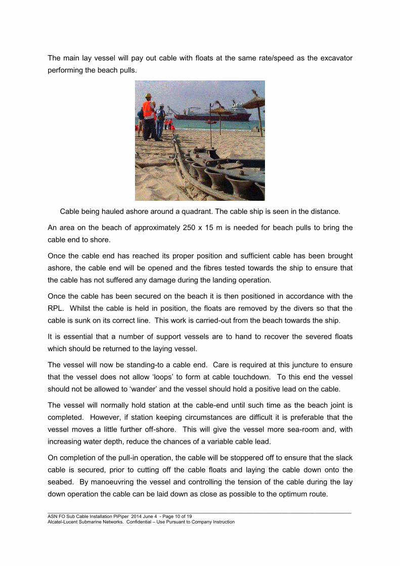
The main lay vessel will pay out cable with floats at the same rate/speed as the excavator performing the beach pulls.
Cable being hauled ashore around a quadrant. The cable ship is seen in the distance.
An area on the beach of approximately 250 x 15 m is needed for beach pulls to bring the cable end to shore.
Once the cable end has reached its proper position and sufficient cable has been brought ashore, the cable end will be opened and the fibres tested towards the ship to ensure that the cable has not suffered any damage during the landing operation.
Once the cable has been secured on the beach it is then positioned in accordance with the RPL. Whilst the cable is held in position, the floats are removed by the divers so that the cable is sunk on its correct line. This work is carried-out from the beach towards the ship.
It is essential that a number of support vessels are to hand to recover the severed floats which should be returned to the laying vessel.
The vessel will now be standing-to a cable end. Care is required at this juncture to ensure that the vessel does not allow ‘loops’ to form at cable touchdown. To this end the vessel should not be allowed to ‘wander’ and the vessel should hold a positive lead on the cable.
The vessel will normally hold station at the cable-end until such time as the beach joint is completed. However, if station keeping circumstances are difficult it is preferable that the vessel moves a little further off-shore. This will give the vessel more sea-room and, with increasing water depth, reduce the chances of a variable cable lead.
On completion of the pull-in operation, the cable will be stoppered off to ensure that the slack cable is secured, prior to cutting off the cable floats and laying the cable down onto the seabed. By manoeuvring the vessel and controlling the tension of the cable during the lay down operation the cable can be laid down as close as possible to the optimum route.

____________________________________________________________________________________________________________________ ASN FO Sub Cable Installation PiPiper 2014 June 4 - Page 11 of 19 Alcatel-Lucent Submarine Networks. Confidential – Use Pursuant to Company Instruction
Following completion of cable testing, the vessel will depart and the divers will release the slack cable from inshore and where necessary move the cable manually, using the slack cable available, to finalise the position of the cable on the seabed. This process will exploit natural features on the seabed, such as channels and gullies, to protect the cable and minimise “suspensions”.
With planned preparation prior to each of the shore ends, controlled lay down during the shore end landings and post lay utilisation of slack cable, shore ends can be laid close to the required final position in good conformity with sea bed topography.
Inspection
Once the cable has been sunk into position and the beach joint has been commenced, it is usual for a diver video inspection of the landing to be carried-out. The inspection is required to:
x Confirm that action was taken, during cable replacement, to avoid small local suspensions
x Record the status of the installation to demonstrate to the System Owners that the landing has been successfully carried-out (or where corrective work is still required).
Video equipment is required for instant replay as soon as the video tape is available from the divers.
Precision of cable positioning – expected tolerance for deviation within the 12 nm.
Cable lay and touchdown positioning is normally based on a mathematical model which for some much more advanced applications may work as a 3 D cable model and use current

____________________________________________________________________________________________________________________ ASN FO Sub Cable Installation PiPiper 2014 June 4 - Page 12 of 19 Alcatel-Lucent Submarine Networks. Confidential – Use Pursuant to Company Instruction
vector information as well from different layers in the water column – within certain depth ranges.
Very precise cable positioning may be required and achieved in shallow water (within safe air diving range) in connection with cable landing operations, where divers can normally support manual cable placement out to around 25 m of water depth.
Based on experience and previous system laid and inspected by ROV, typical positioning accuracy figures could be summarised as follows:
Water Depth Range Precision
10m – 100m: +/- 10-15m
100m – 1000m: +/- 10% WD
1000m – 2000m: +/- 7% WD
> 2000m +/- 5% WD
Submarine Cable Cross section
Please see separate specification - OALC4 Cable Specs.pdf
Embedded:OALC4 Cable
Specs.pdf
Shore-end cable protection and fixing – Articulated Pipe
Cables laid across rocky seabed will be protected by the installation of articulated pipe (AP) , which is fitted by divers after the cable has been landed. AP is extensively used by the submarine cable industry to provide cable protection in the near-shore area where burial is impracticable for environmental or engineering/technical reasons.
AP pipe can be installed with minimal impact to existing marine environmental conditions, both during installation and in the longer term. AP is readily colonised by marine flora and fauna. Like the cable, AP is non-toxic and inert in the marine environment, though in certain situations it may be oxidised by sulphur reducing bacteria.

____________________________________________________________________________________________________________________ ASN FO Sub Cable Installation PiPiper 2014 June 4 - Page 13 of 19 Alcatel-Lucent Submarine Networks. Confidential – Use Pursuant to Company Instruction
The cable with the AP attached will be buried across the beach, both for system security and environmental and public safety reasons, usually to a depth of 2 meters.

____________________________________________________________________________________________________________________ ASN FO Sub Cable Installation PiPiper 2014 June 4 - Page 14 of 19 Alcatel-Lucent Submarine Networks. Confidential – Use Pursuant to Company Instruction
The cable trench is usually dug with hydraulic digging machinery and the beach will be reinstated at the end of burial.
Shore-end cable protection and fixing – burial methods in shallow waters
Plough burial operations are not normally possible in shallow water of less than 15 meters depth, due to the size of the plough and the draught of the cable vessels. Consequently, where such areas have suitable sea-bed characteristics the cable can be buried by other means.
Various kinds of Shallow Water Burial Tool (SWBT) may be used to accomplish the burial. The SWBT is a system that employs water jetting to cut trenches of depths of 0.5 m to 1m in the sea bed, in water up to 20 meters water depth, under the manual control of divers. There is no instrumentation on the burial tool.
The SWBT is usually connected to a pump on a barge or pontoon on which provides high pressure pumped water. Using the high pressure water directed as jets through nozzles on a jetting “sword” the SWBT cuts into the seabed a channel no wider than the sword itself. Sediment will be generated and dispersed to varying degree depending on the seabed substrate characteristics.
Cable installation at crossings of other cables and pipelines
Where the route of the cable crosses in-service telecom or power cables, oil and gas pipelines or other seabed installations, it is not possible to plough without interruption.
Buried in-service cables can be located by use of tone detection equipment. If necessary this may be followed by careful excavation with diver’s jetting/ROV tools to allow verification and identification.
The plough is raised and lowered either side of the intersection (creating a “plough skip” or interruption in the ploughed alignment). This may be done 100-500 meters either side of the intersection, the margin of safety depending on factors like crossing angles, complexity of the seabed installations, etc.
Alternative means must be used to achieve cable burial at and around crossing points to avoid any risk of damage to in-situ infrastructure while ensuring that the new cable is also protected. Divers or ROV then perform the cable burial precisely around the intersection using jetting or other tools.

____________________________________________________________________________________________________________________ ASN FO Sub Cable Installation PiPiper 2014 June 4 - Page 15 of 19 Alcatel-Lucent Submarine Networks. Confidential – Use Pursuant to Company Instruction
Pipeline crossings may be protected by use of concrete mattressing, “uraduct” (a plastic sleeving on the cable to reduce friction with pipe casing) or, rarely, by rock dumping.
The International Cable Protection Committee publishes guidelines intended to assist the cable and pipeline industries to adopt harmonised approach in relation to crossings and ASN attempts to observe these wherever possible. ICPC Recommendation number 3 recommends the considerations to be borne in mind in relation to crossings of telecom and power cables.
In the event that it was proposed that a power interconnector be installed across the telecom cable, in the normal course of events the owners of the crossing power cable would seek a “no objection” or “agreement to cross” from the owners of the crossed telecom cable. Normally this process involves provision by the crossing power cable owner of details of the crossing point location, the physical characteristics of the power cable, details of how the cable is armoured, buried or otherwise protected and an explanation of the methods by which the power cable owner proposes to install the power cable at and around the crossing point. It is usually the case that cable owners can agree quite quickly on a mutually acceptable crossing engineering solution. In some cases cable owners may seek to achieve formal legal “crossing agreements” that set out the parties’ respective roles and responsibilities and define how liabilities may be assigned in the event that damages occur either at the time of installation or as a result of maintenance and repair works that may take place on either system during its operational lifetime. (see Appendix One) .
Final Route Map
A copy of the “as laid” route map will be made available to the licensing authority following completion and acceptance by the customer, of the project.

____________________________________________________________________________________________________________________ ASN FO Sub Cable Installation PiPiper 2014 June 4 - Page 16 of 19 Alcatel-Lucent Submarine Networks. Confidential – Use Pursuant to Company Instruction
APPENDIX ONE – CROSSINGS
CROSSING & BURIAL PROCEDURE
This section provides a description of the basic processes to be used for the safe crossing of existing in-service telecommunications cables. This crossing has been unavoidable, and is based on ICPC (International Cable Protection Committee) Recommendations, in particular, ICPC Recommendation #02 - Recommended Routing and Reporting Criteria for Cables in Proximity to Others. Cable routing was also based on ICPC recommendations, as well as SEACOM recommendations & requirements.
Detailed position information has now been obtained from a route survey operation, including bathymetry (MBES), Side Scan Sonar (SSS), Sub-bottom Profiler (SBP), and where appropriate, magnetometers.
The cable system will be installed from a main lay cable ship (e.g. the CS Ile de Sein), and the majority of this length will be buried. For the burial operations, a burial depth below the seabed as listed in Section 3 will be targeted, using a cable plough deployed from the cable ship. The cable to be installed is from the ASN OALC4 product line, with the specific cable type XXCXXX.
Main Lay Crossing Procedure
The vessel will simultaneously lay and plough-bury the cable. This is done by pulling the cable burial plough behind the vessel, along the seabed, and allowing the cable to pass through the share of the plough. This process allows the cable to be buried below the seafloor.
In order to avoid damage to any in-service cables or pipelines, the installation plan includes a plough recovery (PLUP) from the seabed at a safe distance before the identified crossing location of each crossing. The cable will then be surface laid towards the crossing point.
After surface laying the new cable over the in-service cable, the subsequent plough re-launch (PLDN) is located an agreed distance from the crossing point. This installation method is in keeping with the ICPC guidelines. The highly accurate (GPS) positioning systems that are used to navigate the main-lay vessel and installation plough provide a guarantee that all vessel and plough positions are know at all times better than +/- 10m accuracy, and so the exclusion zone from the crossed cable is sufficient to guarantee the safety of all cable crossings.
While ICPC guidelines recommend a ±500m “no-plough corridor” at crossings, with modern navigation systems it is often possible for this to be reduced to ±250m. If the in-service cable is positively located using modern survey techniques & equipment such as magnetometers, and it matches the reported database position, with the acceptance of the cable owner, it is proposed that the PLUP/PLDN positions be reduced to ±250m.
Slack will be installed in the new cable in the surface laid area, to ensure the cable is laid on the seabed along the agreed corridor.
Depending on cable configurations, no additional protection may be required – e.g. if cable types are matched as much as possible to the crossed in-service cable (i.e. armour on armour, as per ICPC Recommendation #2). Additionally, if the crossed cable is buried, there is no possibility of relative movement of the cables causing abrasion.
The following illustrations show a typical main lay cable crossing procedure:

____________________________________________________________________________________________________________________ ASN FO Sub Cable Installation PiPiper 2014 June 4 - Page 17 of 19 Alcatel-Lucent Submarine Networks. Confidential – Use Pursuant to Company Instruction
STEP 1: Cable plough buried to PLUP location (250m or 500m away from in service
cable)
STEP 2: Plough recovered to deck
STEP 3: New cable surface laid across existing in service cable
STEP 5: Plough launched at PLDN location (250 or 500m away from existing cable)
Seabed
Surface Lay 250m or 500m Surface Lay
In-Service Cable
Water Level
In-Service Cable
Seabed
Surface Lay
Water Level
In-Service Cable
Seabed
250m or 500m
Water Level
In-Service Cable Seabed
250 or 500m
Water Level
____________________________________________________________________________________________________________________ ASN FO Sub Cable Installation PiPiper 2014 June 4 - Page 18 of 19 Alcatel-Lucent Submarine Networks. Confidential – Use Pursuant to Company Instruction
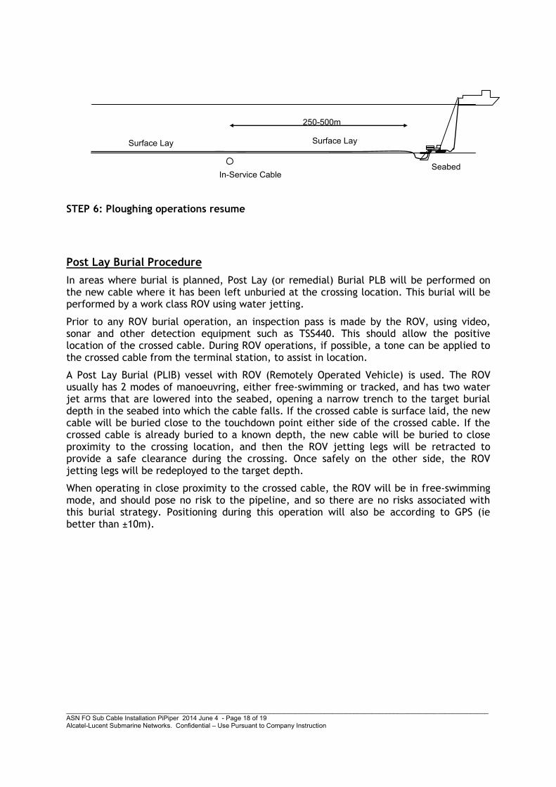
STEP 6: Ploughing operations resume
Post Lay Burial Procedure
In areas where burial is planned, Post Lay (or remedial) Burial PLB will be performed on the new cable where it has been left unburied at the crossing location. This burial will be performed by a work class ROV using water jetting.
Prior to any ROV burial operation, an inspection pass is made by the ROV, using video, sonar and other detection equipment such as TSS440. This should allow the positive location of the crossed cable. During ROV operations, if possible, a tone can be applied to the crossed cable from the terminal station, to assist in location.
A Post Lay Burial (PLIB) vessel with ROV (Remotely Operated Vehicle) is used. The ROV usually has 2 modes of manoeuvring, either free-swimming or tracked, and has two water jet arms that are lowered into the seabed, opening a narrow trench to the target burial depth in the seabed into which the cable falls. If the crossed cable is surface laid, the new cable will be buried close to the touchdown point either side of the crossed cable. If the crossed cable is already buried to a known depth, the new cable will be buried to close proximity to the crossing location, and then the ROV jetting legs will be retracted to provide a safe clearance during the crossing. Once safely on the other side, the ROV jetting legs will be redeployed to the target depth.
When operating in close proximity to the crossed cable, the ROV will be in free-swimming mode, and should pose no risk to the pipeline, and so there are no risks associated with this burial strategy. Positioning during this operation will also be according to GPS (ie better than ±10m).
Seabed
Surface Lay
250-500m
Surface Lay
In-Service Cable

19 / 19
1. CROSSING INFORMATION
All information below is “as found” after survey.
Ref Crossed System Name
Cable Status
Latitude (WGS-84)
Longitude (WGS-84)
Depth (m)
Cum KP Dist (km)
New Cable Type
New cable to be Buried?
Crossing Angle
Nearest Repeater (km)
Crossed Cable Type
Method Located
Change from Previous Crossing Pack?
1

ICPC Recommendation No. 3, Issue: 8 Issue Date: 19 August 2002
Page 1 of 7 ICPC Handbook Section No: 12.3
ICPC Recommendation
Recommendation No. 3 Criteria to be Applied to Proposed Crossings Between Submarine Telecommunications Cables and Pipelines/Power Cables

ICPC Recommendation No. 3, Issue: 8 Issue Date: 19 August 2002
Page 2 of 7 ICPC Handbook Section No: 12.3
Contact for Enquiries and Proposed Changes
If you have any questions regarding this document or suggestions for improving it, please contact:
International Cable Protection Committee PO Box 150 Lymington SO41 6WA United Kingdom
Secretary: Mr. Graham Marle Tel: + 44 1590 681 673 Fax: + 44 870 432 7761 E-mail: [email protected] ICPC Web-site: www.iscpc.org
DISCLAIMER
An International Cable Protection Committee ("ICPC") Recommendation ("Recommendation") implies a consensus of those substantially concerned with its scope and provisions. A Recommendation is intended as a guide to aid cable owners and other seabed users in promoting the highest goals of reliability and safety in the submarine cable environment. The existence of a Recommendation does not in any respect preclude anyone, whether he has approved the Recommendation or not, from laying or repairing undersea cables or employing procedures to these ends which may be required by the ordinary practice of seamanship or by the special circumstances of each case, but which may not be conforming to the Recommendation. The ICPC does not develop standards and will in no circumstances give an interpretation of a Recommendation in the name of the ICPC. The ICPC and its members do not accept any liability for any errors in the Recommendation or for any consequences resulting from its use as a planning guide. Nothing in this Recommendation should be viewed as relieving anyone from the rights and obligations of seabed users under international law, including but not limited to the United Nations Convention of the Law of the Sea ("UNCLOS"). NB: ICPC Recommendations are subject to periodic review and users are cautioned to obtain the latest issues. This Recommendation may be revised or withdrawn at any time without further notice to the recipient.

ICPC Recommendation No. 3, Issue: 8 Issue Date: 19 August 2002
Page 3 of 7 ICPC Handbook Section No: 12.3
TABLE OF CONTENTS Disclaimer .................................................................................................................................. 2
Table Of Contents ...................................................................................................................... 3
1. Introduction ........................................................................................................................ 4
2. Basic Considerations .......................................................................................................... 4
2.1 All Crossings .......................................................................................................... 4
2.2 Existing Telecommunications Cable Crossed By New Pipeline/Power Cable...... 4
2.3 Existing Pipeline/Power Cable Crossed By Telecommunications Cable .............. 5
3. Crossing Agreement........................................................................................................... 6
4. Conclusion.......................................................................................................................... 7
5. References .......................................................................................................................... 7
6. Definitions.......................................................................................................................... 7
7. Attachments........................................................................................................................ 7

ICPC Recommendation No. 3, Issue: 8 Issue Date: 19 August 2002
Page 4 of 7 ICPC Handbook Section No: 12.3
1. INTRODUCTION The continued increase in both the numbers of submarine cables and the exploitation of oil and gas from the seabed inevitably means that there will more cases of crossings between telecommunications cables, power cables and pipelines. The purpose of this document is to give guidance to members who are faced with this situation for the first time. It is also a matter for consideration that the pipeline or power cable owner involved in a crossing may well have other pipeline/cable crossings in other parts of the world and, if one telecommunications cable owner were to allow a crossing to take place without certain minimum standards, this could adversely effect the negotiations of other telecommunications cable owners.
It must first be stated that every pipeline/cable crossing will have characteristics unique to that crossing, and therefore each crossing has to be considered separately. However there are still certain basic questions to be asked as the first step in considering that crossing, and to establishing the areas of concern and their solutions.
2. BASIC CONSIDERATIONS 2.1 All Crossings
2.1.1 Nature of seabed.
2.1.2 Type of cable.
2.1.3 Size of pipeline.
2.1.4 Notification of crossing proposal to other seabed users
2.2 Existing Telecommunications Cable Crossed By New Pipeline/Power Cable.
2.2.1 Is cable buried? Deliberate or self-burial? If so, to what depth?
2.2.2 Will pipeline/power cable be trenched? If so, then to what depth? What trenching equipment will be used?
2.2.3 Will the pipeline have cathodic protection? If so, what is the planned distance between anodes? If possible, can this distance be increased at the crossing point? Can the anodes be arranged so that the cable is in the mid-50% distance between anodes?
2.2.4 If power cable, what are its feed voltages. Is it adequately screened? What impact would any residual electro-magnetic field strength have upon adjacent telecommunications cable and/or repeaters?
2.2.5 Is the proposed crossing in the vicinity of a repeater or equaliser? If so, will the presence of the pipeline prevent the recovery of that repeater/equaliser in the prevailing water depth by normal cable repair methods? Can the pipeline/power cable be altered in the planning stage to increase the distance from the repeater/equaliser?
2.2.6 Is there any local legislation requirement protecting submarine cables with which the pipeline/power cable owner must comply?

ICPC Recommendation No. 3, Issue: 8 Issue Date: 19 August 2002
Page 5 of 7 ICPC Handbook Section No: 12.3
2.2.7 If it becomes necessary to cut and peel back the cable, are there adequate alternative routes to which traffic may be transferred?
2.2.8 Does the proposed pipeline/power cable route cross the cable at approximately right angles? If not, then serious maintenance problems could arise to both systems and, therefore, can the pipeline/power cable route be altered in the planning stage?
2.2.9 Has a minimum of two weeks notification been given to all involved parties prior to any operational activity that could affect the performance of working international telecommunications services?
2.3 Existing Pipeline/Power Cable Crossed By Telecommunications Cable
2.3.1 Is pipeline/power cable trenched? If so, to what depth? Has there been natural or artificial backfill? If so, what depth of cover exists now over the pipeline/power cable? Is this cover adequate for the concerns of the pipeline/power cable owner and, if not, what additional depth and type of separation will he require?
2.3.2 Does the pipeline have cathodic protection? If so, what is the distance between anodes? Are the anode positions accurately known? Can the cable lay be arranged so that the cable is in the mid-50% distance between anodes?
2.3.3 Does the pipeline/power cable owner have any specific concerns for the safety of the pipeline/power cable which will have to be considered? Will he require any artificial separation to be installed between pipeline/power cable and telecommunications cable? Will the telecommunications cable owner consider artificial separation to be necessary to avoid chafing damage to the telecommunications cable?
2.3.4 Is there any local legislation requirement regarding operating in the vicinity of pipelines/power cables to be complied with?
2.3.5 Does the proposed cable route cross the pipeline/power cable at approximately right angles? If not, then serious maintenance problems could arise to both systems and, therefore, the telecommunications cable route shall be altered in the planning stage.
2.3.6 Does the proposed telecommunications cable system section sheet place a repeater in close proximity to the pipeline/power cable crossing? This could cause later maintenance problems in the event of repeater replacement becoming necessary, therefore, can the section sheet be altered in the planning stage?
2.3.7 If the telecommunications cable is to be buried, either during or after the lay, how close to the pipeline/power cable will the operator allow the burial equipment to approach?

ICPC Recommendation No. 3, Issue: 8 Issue Date: 19 August 2002
Page 6 of 7 ICPC Handbook Section No: 12.3
2.3.8 If burial equipment is not allowed within a given distance from the pipeline/power cable, what protection will be required for the telecommunications cable? Double armouring? Rock dumping? Are there any local legislation or local authority rules to be considered in this context? Fishing authorities may require coverage of the crossing to remove obstacles to fishing gear.
If Section 2.3 applies, then the telecommunications cable will be laid over the pipeline/power cable. If Section 2.2 applies, the telecommunications cable owner must decide on his policy as to whether to allow the pipeline/power cable on top of the telecommunications cable or to require a cut and peel back solution and, if the latter, as the pipeline/power cable owner will be required to pay for the costs, this must be justifiable. In all cases consideration must be given to protection for the telecommunications cable for its lifetime, with regard to both physical damage and cathodic corrosion. Therefore, if Section 2.2 applies to an old telecommunications cable, the protection requirements may be less onerous than for a new one.
3. CROSSING AGREEMENT International Law is inadequate to protect the interests of the parties involved in a pipeline/power and telecommunications cable crossing and, where a crossing occurs within the legal jurisdiction of a State, the relevant legislation is also rarely sufficient. In addition, the recourse to any court following a conflict of interest is a lengthy and expensive matter. It is therefore recommended, in the interests of both parties, to negotiate an Agreement to cover any pipeline/cable crossing. A sample crossing agreement is available on request to the ICPC Secretary, or members can obtain directly from the ICPC handbook (Section 28). The contents of an Agreement are a matter for the individual parties, but it is recommended that the following points shall be covered:
3.1 Clauses to define the liabilities and rights of both parties.
3.2 The exclusion/inclusion of consequential losses. It is recommended that consequential losses shall be excluded.
3.3 Definition of a specific area in the vicinity of the crossing within which the Agreement will operate.
3.4 A general statement of the method of installation of the pipeline or cable as appropriate. It is not recommended that installation procedures be included in the body of the Agreement as they may require alteration prior to or during the operation. They may of course be included in the document as an appendix.
3.5 Future maintenance of the pipeline and cable(s). This may include the method by which notification of operations by each party is given to the other.
3.6 Definition of the expiry of the Agreement. If section 3.5 is covered then the normal time is at the removal from service of either the pipeline or cable(s), whichever comes first.
3.7 Provision of representatives from one party to the other party's operations and their rights and limitation of their authority.

ICPC Recommendation No. 3, Issue: 8 Issue Date: 19 August 2002
Page 7 of 7 ICPC Handbook Section No: 12.3
4. CONCLUSION Sections 2 and 3 are not intended to be a complete or definitive list of issues that shall be addressed when pipeline/power cables cross telecommunications. There will be items listed which may not be applicable to some areas of the world, and equally other areas of the world may produce problems not listed above.
The most important consideration is that as soon as it becomes apparent that a pipeline/cable crossing will occur an exchange of information must be initiated at the earliest possible moment. In addition, a minimum of two weeks notification shall be given to all involved parties prior to any operational activity that could affect the performance of working international telecommunications services.
Pipeline/power cable owners who have not crossed a telecommunications cable before often do not appreciate the problems involved and, therefore, if a telecommunications cable owner learns of a pipeline/power cable project that may affect the integrity of his cable he would be wise to make the first approach. Equally, a telecommunications cable owner who has not crossed a pipeline/power cable before shall not assume that that it is a simple or inexpensive operation.
All discussions and negotiations shall be conducted with the understanding that both parties have legitimate concerns. The vast majority of problems can be avoided if they are discussed before budgets are set and the contracts for submerged plant are granted, whether that plant be for pipeline/power or telecommunications cable.
Approved: EC 2000
5. REFERENCES Document Number Title
ICPC Handbook Sec.28 Draft Pipeline Crossing Agreement
6. DEFINITIONS The following words, acronyms and abbreviations are referred to in this document.
Term Definition
7. ATTACHMENTS Document Number Title

OALC-4 Submarine Cable
September 2009 O A L C – 4 Page 4
All rights reserved. Copy, use and communication of this document or any of its contents is not permitted without written authorisation from Alcatel-Lucent.
1. GENERAL
1.1 GENERAL DESIGN CONSIDERATIONS
The main design function of a cable is to protect the optical fibre transmission path over the entire service life of the system, including laying, burial, and recovery operations.
A secondary function is that its metallic elements are used either to feed an electric current to the repeaters or to monitor on a permanent basis the status of the transmission system and to localise cable breaks.
The OALC-4 cable design can accommodate up to 8 pairs of fibres. The fibres are housed in a jelly filled steel tube surrounded by two layers of steel wires that form a protective vault against pressure and external aggressions, and provide tensile strength. This vault is then enclosed in a hermetically sealed copper tube and insulated with a layer of polyethylene to form the deep sea LW cable. This cable is used with a DC resistance of 1 and/or 1.6 ohm/km, depending on actual system requirements.
For shallow water applications, external layers of steel armour wires are added, different types of armouring being available to suit route conditions and installation methods.
The cable design ensures that negligible strain and ultra low pressure are applied to the fibres in normal operation. Even if the cable breaks, high strain on the fibres and sea-water ingress are limited to a short length, so that the bulk of the cable will remain serviceable.
These high performances are made possible thanks to a cable structure that isolates fibres from mechanical stresses under normal operation conditions. This is achieved with a unique design in which fibres lay freely in a steel tube. As a result, the cable can practically house any type of fibre provided it can handle a proof- test.
Even in the most adverse conditions such as cable recovery, cables are dimensioned so that stress applied to the fibres never reaches critical levels. The combination of loose structure and fibre proof-test prevents any fibre break that would be caused by ageing stress during the design life of the system.
Whenever possible, the raw materials selected are of the same type as those used in previous generations of coaxial and optical fibre cables, which have demonstrated more than 20 years of total reliability.

OALC-4 Submarine Cable
September 2009 O A L C – 4 Page 5
All rights reserved. Copy, use and communication of this document or any of its contents is not permitted without written authorisation from Alcatel-Lucent.
Alcatel-Lucent, however, reserves the right to make any modification to the production, inspection or raw material specifications where this modification improves the efficiency of the production or the quality of the product.
1.2 DESCRIPTION OF CABLES, GENERAL CHARACTERISTICS AND DEFINITIONS
1 .2 .1 Deep sea cable
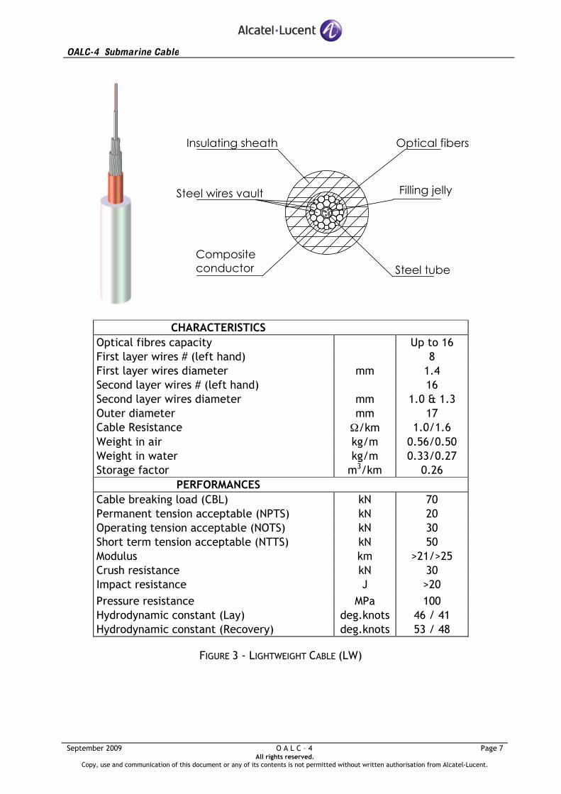
1.2.1.1 Lightweight cable
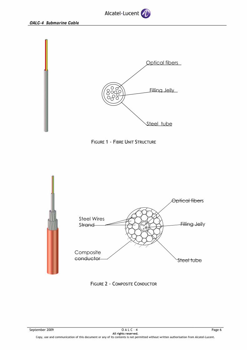
Optical fibres are housed in a steel tube, filled with a non-hygroscopic compound. This structure, shown in Fig. 1, is called fibre unit structure.
The fibre unit structure is protected by a very high strength steel wire vault. This vault is surrounded by a copper tube, produced by seam welding a tape formed around the vault and swaging it onto the strand. This structure, shown in Fig. 2, is called Composite Conductor.
Axial water penetration is limited by injection of a water blocking material between the vault steel wires.
The Composite Conductor is then polyethylene insulated. The polyethylene insulation provides abrasion resistance and high voltage insulation. This completes the design of the lightweight (LW) cable, shown in Fig. 3, used for deep-sea deployment.
The OALC-4 LW cable may be used at any sea depth down to 8000m.
1.2.1.2 Lightweight protected cable
The lightweight cable structure is protected by an additional coated metallic tape formed around the insulated sheath with an overlap and covered by a second sheath of black high density polyethylene to form the LWP cable, shown in Fig. 4. This design provides an additional protection against abrasion, fishing hook penetration and fish-bite damage.
The OALC-4 LWP cable may be used at any sea depth down to 7000m, but is generally used between 1000 and 3500m.
OALC-4 Submarine Cable
September 2009 O A L C – 4 Page 6
All rights reserved. Copy, use and communication of this document or any of its contents is not permitted without written authorisation from Alcatel-Lucent.
Optical fibers
Steel tube
Filling Jelly
FIGURE 1 - FIBRE UNIT STRUCTURE
Steel tube
Filling JellySteel WiresStrand
Compositeconductor
Optical fibers
FIGURE 2 - COMPOSITE CONDUCTOR
OALC-4 Submarine Cable
September 2009 O A L C – 4 Page 7
All rights reserved. Copy, use and communication of this document or any of its contents is not permitted without written authorisation from Alcatel-Lucent.
Steel tube
Optical fibers
Compositeconductor
Steel wires vault Filling jelly
Insulating sheath
CHARACTERISTICS
Optical fibres capacity Up to 16 First layer wires # (left hand) 8 First layer wires diameter mm 1.4 Second layer wires # (left hand) 16 Second layer wires diameter mm 1.0 & 1.3 Outer diameter mm 17 Cable Resistance Ω/km 1.0/1.6 Weight in air kg/m 0.56/0.50 Weight in water kg/m 0.33/0.27 Storage factor m3/km 0.26
PERFORMANCES Cable breaking load (CBL) kN 70 Permanent tension acceptable (NPTS) kN 20 Operating tension acceptable (NOTS) kN 30 Short term tension acceptable (NTTS) kN 50 Modulus km >21/>25 Crush resistance kN 30 Impact resistance J >20 Pressure resistance MPa 100 Hydrodynamic constant (Lay) deg.knots 46 / 41 Hydrodynamic constant (Recovery) deg.knots 53 / 48
FIGURE 3 - LIGHTWEIGHT CABLE (LW)

OALC-4 Submarine Cable
September 2009 O A L C – 4 Page 8
All rights reserved. Copy, use and communication of this document or any of its contents is not permitted without written authorisation from Alcatel-Lucent.
Insulating sheath Fiber Unit structure & composite conductor
Outer sheath
Metallic screen
CHARACTERISTICS
Cable core diameter mm 17 First layer wires # (left hand) 8 First layer wires diameter mm 1.4 Second layer wires # (left hand) 16 Second layer wires diameter mm 1.0 & 1.3 Outer diameter mm 23 Cable Resistance Ω/km 1.0/1.6 Weight in air kg/m 0.81/0.75 Weight in water kg/m 0.38/0.32 Storage factor m3/km 0.48
PERFORMANCES Cable breaking load (CBL) kN 70 Permanent tension acceptable (NPTS) kN 20 Operating tension acceptable (NOTS) kN 30 Short term tension acceptable (NTTS) kN 50 Modulus km >17/>22 Crush resistance kN 30 Impact resistance J >20 Pressure resistance MPa 100 Hydrodynamic constant (Lay) deg.knots 42 / 39 Hydrodynamic constant (Recovery) deg.knots 49 / 45
FIGURE 4 - LIGHTWEIGHT PROTECTED CABLE (LWP)

OALC-4 Submarine Cable
September 2009 O A L C – 4 Page 9
All rights reserved. Copy, use and communication of this document or any of its contents is not permitted without written authorisation from Alcatel-Lucent.
1 .2 .2 Armoured cables
Armoured cables use the lightweight (LW) deep sea cable as central core structure, with additional external protection provided where required by conditions and nature of the seabed and installation methods.
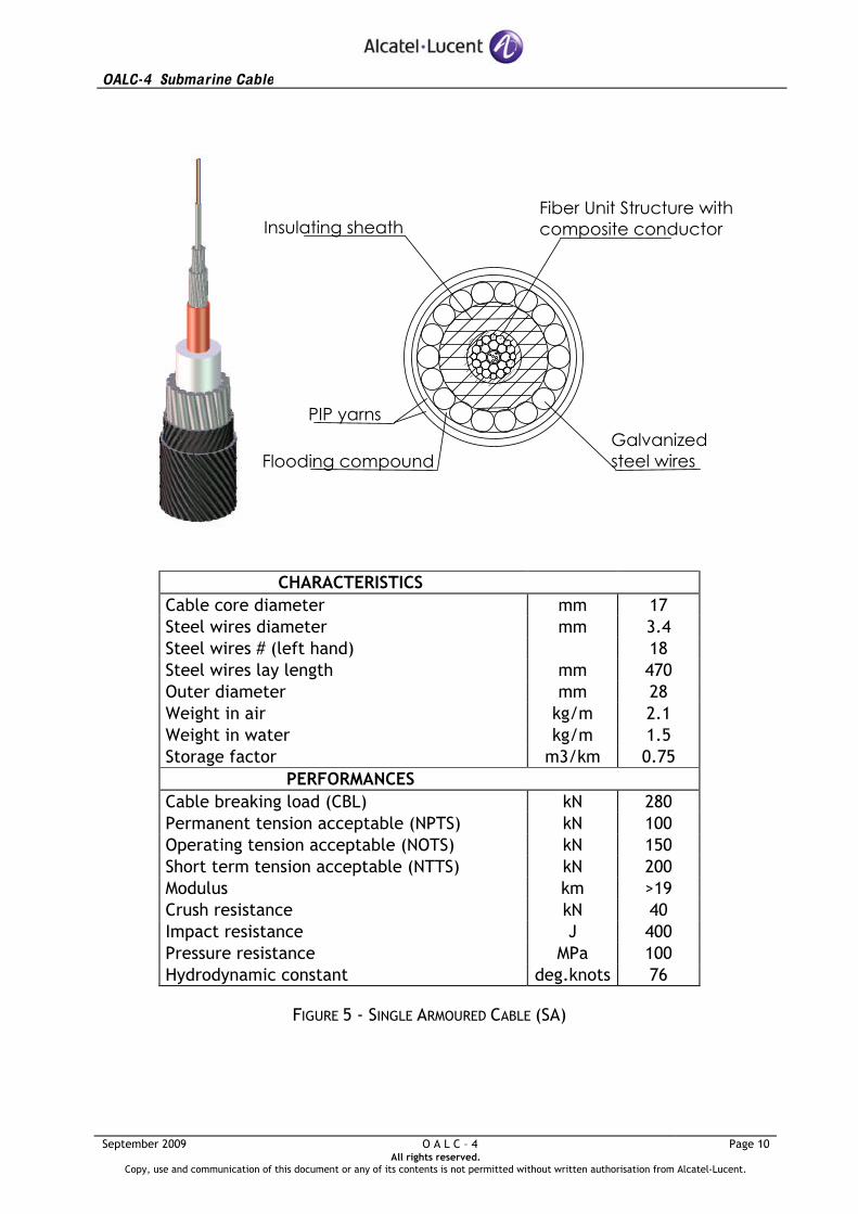
1.2.2.1 Single Armoured cable (SA)
SA cable is made by stranding a single layer of high strength galvanised steel wires over the lightweight (LW) cable structure. The steel wires are flooded with bituminous compound and covered by polypropylene yarns. This cable, shown in Fig. 5, is normally used where full protection by burial is possible. It may be used at any sea depth between 0 and 2000m; in deep sea applications the transition with the LW/LWP cable is to be recovered from the SA cable.
1.2.2.2 Double Armoured cable (DA)
DA cable is made by adding a second layer of galvanised steel wires around the SA cable, flooded with bituminous compound and covered with polypropylene yarns. This cable, shown in Fig. 6, is normally used for surface laying in shallow water where burial is not required (no threat) or to add additional protection where burial was originally thought to be possible but prevented due to the presence of existing in-service cables or pipelines. It may be used at any sea depth between 0 and 500m but is generally used between 0 and 200m.
OALC-4 Submarine Cable
September 2009 O A L C – 4 Page 10
All rights reserved. Copy, use and communication of this document or any of its contents is not permitted without written authorisation from Alcatel-Lucent.
Galvanizedsteel wires
Fiber Unit Structure withcomposite conductorInsulating sheath
PIP yarns
Flooding compound
CHARACTERISTICS
Cable core diameter mm 17 Steel wires diameter mm 3.4 Steel wires # (left hand) 18 Steel wires lay length mm 470 Outer diameter mm 28 Weight in air kg/m 2.1 Weight in water kg/m 1.5 Storage factor m3/km 0.75
PERFORMANCES Cable breaking load (CBL) kN 280 Permanent tension acceptable (NPTS) kN 100 Operating tension acceptable (NOTS) kN 150 Short term tension acceptable (NTTS) kN 200 Modulus km >19 Crush resistance kN 40 Impact resistance J 400 Pressure resistance MPa 100 Hydrodynamic constant deg.knots 76
FIGURE 5 - SINGLE ARMOURED CABLE (SA)

OALC-4 Submarine Cable
September 2009 O A L C – 4 Page 11
All rights reserved. Copy, use and communication of this document or any of its contents is not permitted without written authorisation from Alcatel-Lucent.
Galvanized steel wires, first layer
Fiber Unit Structure with composite conductor
Insulating sheath Ø 17 mm
PIP yarn
Flooding compound Galvanized steel wires, second layer
CHARACTERISTICS
Cable core diameter mm 17 First layer steel wires diameter mm 3.4 First layer steel wires # (left hand) 18 First layer steel wires lay length mm 470 Second layer steel wires diameter mm 3.4 Second layer steel wires # (left hand) 24 Second layer steel wires lay length mm 510 Outer diameter mm 37.5 Weight in air kg/m 4.0 Weight in water kg/m 2.8 Storage factor m3/km 1.4
PERFORMANCES Cable breaking load (CBL) kN 545 Permanent tension acceptable (NPTS) kN 200 Operating tension acceptable (NOTS) kN 300 Short term tension acceptable (NTTS) kN 400 Modulus km >19 Crush resistance kN 40 Impact resistance J 400 Pressure resistance MPa 100 Hydrodynamic constant deg.knots 90
FIGURE 6 – DOUBLE ARMOURED CABLE (DA)

OALC-4 Submarine Cable
September 2009 O A L C – 4 Page 12
All rights reserved. Copy, use and communication of this document or any of its contents is not permitted without written authorisation from Alcatel-Lucent.
The standard tension characteristics of the OALC-4 cables as defined below are summarised in Table 1.
The Nominal Permanent Tensile Strength (NPTS) is the maximum tension that the cable can withstand during the system lifetime without any impairment of fibres or degradation of the overall cable performance.
The Nominal Operating Tensile Strength (NOTS) is the maximum tension that can be applied to the cable during the time necessary to make cable joints, without significant reduction of NPTS.
The Nominal Transient Tensile Strength (NTTS) is the maximum tension that can be applied to the cable during a cumulative period of one hour, without significant reduction of NPTS/NOTS.
The Ultimate Cable Tensile Strength (UTS) is the maximum tension that can be applied to the cable without causing cable break.
Characteristics Unit LW LWP SA DA Cable core diameter mm 17 17 17 17 1st layer steel wires diameter mm - - 3.4 3.4 1st layer steel wires # (left hand) - - 18 18 1st layer steel wires lay length mm - - 470 470 2nd layer steel wires diameter mm - - - 3.4 2nd layer steel wires # (left hand) - - - 24 2nd layer steel wires lay length mm - - - 510 Outer diameter mm 17 23 28 37.5 Weight in air 1Ω/km 1.6Ω/km
kg/m kg/m
0.56 0.50
0.81 0.75
2.1 2.0
4.0 3.9
Weight in water 1Ω/km 1.6Ω/km
kg/m kg/m
0.33 0.27
0.38 0.32
1.5 1.4
2.8 2.8
Performances UTS kN 70 70 280 545 NPTS kN 20 20 100 200 NOTS kN 30 30 150 300 NTTS kN 50 50 200 400 Modulus 1Ω/km 1.6Ω/km
km km
>21 25
17 22
>19 20
>19 >19
Hydrodynamic constant for recovery 1Ω/km 1.6Ω/km
deg.knots deg.knots
53 48
49 45
76 73
90 90
TABLE 1 - CABLES CHARACTERISTICS (SUMMARY)