Embed Size (px)
Citation preview
Solar
IEA SHC Task 49
SolarPACES Annex IV
Solar Process Heat for Production and Advanced Applications
Methodologies and Software Tools for Integrating Solar Heat into Industrial Processes
Version 2.0, February, 2015
Authors: Pierre Krummenacher, Bettina Muster
Target audience:
This document is primarily intended for the process integration community, and aims to present
specific issues of, and solutions/approaches for, the integration of solar heat into industrial
processes. It does not describe Process Integration nor present the basics of Pinch Analysis.
Readers not familiar with these topics should refer to the Task 49 report, Integration Guideline,
Chapter 4, which is targeted to the community of solar engineers.
IEA SHC Task 49 Solar Process Heat for Production and Advanced Applications SolarPACES Annex IV
2
Contents
1 Description of IEA SHC Task 49 ............................................................................................. 3
1.1 Background ..................................................................................................................... 3 1.2 Task objectives................................................................................................................ 6 1.3 Task 49 scope ................................................................................................................. 7 1.4 Task 49 Subtask B, activity B1: Development of advanced pinch and storage
management tool(s) ....................................................................................................... 7
2 Integration methodologies of solar heat into industrial processes ........................................... 9
2.1 Combining solar heat with energy efficiency actions........................................................ 9 2.2 Solar heat – a special hot utility / heat source.................................................................. 9 2.3 PI methodologies extended to renewables – a short review .......................................... 10 2.4 Overview of solar heat integration modes and concepts ................................................ 11 2.5 A simple example process ............................................................................................. 12 2.6 Scoping and screening process integration opportunities .............................................. 13 2.7 Practice relevant HEN & heat storage design ................................................................ 18
3 Workflow for integration of solar process heat and process integration software tools .......... 20
3.1 PinCH ............................................................................................................................ 23 3.2 SOCO............................................................................................................................ 24
4 Conclusions & further work ................................................................................................... 26
5 Literature references ............................................................................................................. 27
IEA SHC Task 49 Solar Process Heat for Production and Advanced Applications SolarPACES Annex IV
3
1 Description of IEA SHC Task 49
1.1 Background
Solar Heat for Industrial Processes (SHIP) has significant potential to cover the useful heat demand of
certain industry sectors. IEA SHC Task 49 is working to foster the uptake of this technology.
This report includes a brief introduction on the technical potential of SHIP and then outlines the
current status of SHIP applications.
It is well known that the industry sector represents a high share of the final energy consumption in
most developed countries. In the EU-28, a quarter of the final energy consumption can be linked to
the industry sector.
Figure 1: Final energy consumption, EU-28, 2012, Eurostat.
The Joint Research Centre [1] categorizes industrial heat demand into three temperature groupings.
Figure 2 shows that the majority of the useful heat demand is required at high temperatures that are
out of the reach of conventional solar heat collectors. However, a huge potential remains for low
temperature heat demands (< 100°C) that can be delivered using conventional solar heat collectors,
and medium temperature heat demands (100-400°C) that can be provided using advanced collector
technologies.
IEA SHC Task 49 Solar Process Heat for Production and Advanced Applications SolarPACES Annex IV
4
Figure 2: Breakdown of useful heat demand for EU-27 industry in 3 temperature levels.
A closer look at the different industry sectors reveals that the majority of high temperature heat
demand exists in the various metal industries (iron, steel, aluminum), non-metallic mineral industries
(especially, cement industry) and partly the chemical industry.
The highest demands on low and medium temperature heat come from the food, drink and tobacco
industry and the paper and painting industry. It is worthwhile mentioning that the remaining demand is
in the chemical industry and the machinery industry because metal processing – which can be
assigned to both industry categories – is also an important target for SHIP applications. The
production capacity of the textile industry in Europe has dropped dramatically for many years,
however, textile processing remains a great potential for SHIP in other regions, such as China and
Southeast Asia.
Figure 3: Breakdown of useful heat demand for EU-27 industry for 3 temperature levels for the main industry
sectors in Europe.
As part of SHC Task 49, a survey on SHIP applications was conducted. So far 164 SHIP applications
have been surveyed, however, only 135 have sufficient data to be published on ship-plants.info.
Figure 4 shows the distribution of the SHIP applications worldwide.
IEA SHC Task 49 Solar Process Heat for Production and Advanced Applications SolarPACES Annex IV
5
Figure 4: Location and number of reported SHIP applications.
According to the SHIP database, 141.355 m² of gross area solar heat collectors for industrial
processes are installed worldwide. Most of these systems are experimental and relatively small in
scale. However, in recent years the number of very large applications has increased significantly. An
example of such a large-scale installation is at a copper mine in Chile, which pushes the country to
first place in installed collector area for SHIP.
In total, 20 SHIP applications have a gross collector area > 1000 m², which represents 77% of the
total installed gross collector area.
Figure 5: Gross collector area of SHIP applications in different countries.
When tapping into the potential of SHIP it is important to evaluate the thermal processes and the
thermal energy supply of the industry site in question. The methodology that has been developed to
IEA SHC Task 49 Solar Process Heat for Production and Advanced Applications SolarPACES Annex IV
6
achieve a thermal energy supply in industry with minimal greenhouse gas emissions is based on a
three-step approach:
1. Technological optimization of the processes (e.g., increased heat and mass transfer, lower pro-
cess temperature) and solar thermal system (e.g., operation of solar field, integration schemes,
control, safety issues, etc.).
2. System optimization (enhancing energy efficiency using, for example, Pinch Analysis for the
heat exchanger network of a total production site).
3. Integration of renewable energy/solar thermal energy (based on exergetic considerations).
Over the last two years, the awareness for solar process heat in industry has increased and new solar
thermal systems have been installed as noted above. This positive development should now be
supported by further research and development in the key research questions of solar process heat.
After completion of the IEA SHC Task 33/SolarPACES Annex IV, key areas for further technological
development, which should be treated in the context of a new Task, were identified:
Process heat collector development with heat loss control and maximization of energy collection;
Material research with improvement of components on a higher temperature level and better ma-
terials for concentrated optics; and
Process heat collector testing for working temperatures above 100°C.
The content of the current IEA SHC Task 49 were defined based on this knowledge out of IEA SHC
Task 33/SolarPACES Annex IV and other position papers, such as the strategic research agenda of
the European Solar Thermal Technology Platform and the experience of several national projects in
the field of solar process heat.
1.2 Task objectives
Subtask A: Process Heat Collectors:
Improvement of solar process heat collectors and collector loop components
Comparison of collectors with respect to technical and economic conditions
Comprehensive recommendations for standardized testing procedures
Subtask B: Process Integration and Process Intensification combined with Solar Process Heat:
Development of advanced pinch and storage management tool(s)
Survey on integration methodologies for solar process heat
Develop System concepts and integration guideline
Survey and dedicated Workshop on new process technologies
Identification of the increasing potentials and compendium of on going activities and existing pilot
plants/case studies
Subtask C: Design Guidelines, Case Studies and Dissemination:
Design guidelines
Simulation tools
Performance assessment methodology
Monitoring of demonstration projects and “best practice” projects
IEA SHC Task 49 Solar Process Heat for Production and Advanced Applications SolarPACES Annex IV
7
Dissemination of Task results
Market deployment
Potential study
1.3 Task 49 scope
Applications, systems and technologies that are included in the scope of this Task are:
All industrial processes that are thermal driven and running in a temperature range up to 400°C.
Solar thermal systems using air, water, low pressure steam or oil as a heat carrier, that is not lim-
ited to a certain heat transfer medium in the solar loop.
All types of solar thermal collectors for an operating temperature level up to 400°C are addressed:
uncovered collectors, flat-plate collectors, improved flat-plate collectors - for example hermetically
sealed collectors with inert gas fillings, evacuated tube collectors with and without reflectors, CPC
collectors, concentrating collectors with stationary receivers, parabolic trough collectors, Fresnel
collectors, etc.
Technologies for industrial application that can be driven by sunlight or specific spectrums (e.g.
UV).
Specific process engineering technologies to which solar heat has to be supplied, such as
technologies for desalinating seawater, industrial cooling applications and electricity generation are
not the main focus of the Task. They may be considered to a certain extent if there is strong interest
from industry.
For cooling applications, the work will be restricted to the adaptation of the results of IEA SHC Task
38 to industrial applications.
The foreseen activities in the field of heat storage management will not deal with the development of
storage technologies and the application of new storage materials. This work will be addressed in IEA
SHC Task 42 and its follow-up activities.
There is a link of IEA SHC Task 49 to the activities in IEA SHC Task 45 on large scale systems due to
the size of the solar thermal systems and the challenges faced by both applications. The main
differences between IEA SHC Task 49/IV and IEA SHC Task 45 can be seen in:
Dependence of the solar thermal system design on the industrial process layoutCombination
of process intensification and solar thermal systems
Dealing with new applications
Different temperature levels (SHIP up to 400°C) and more relevance on the development and
application of concentrated systems
Based on the higher temperatures different challenges on material, fluids, collector and com-
ponents behavior are considered
Different stagnation behavior due to batch processes and different hot storage management
Detailed focus on industrial processes in combination with solar thermal collectors.
1.4 Task 49 Subtask B, activity B1: Development of advanced pinch and storage management tool(s)
The general methodology for the integration of solar thermal energy into industrial processes was
developed during IEA SHC TASK 33/SolarPACES Annex IV. It was shown that the Pinch analysis for

IEA SHC Task 49 Solar Process Heat for Production and Advanced Applications SolarPACES Annex IV
8
the total production site and - building upon it - the design of an optimized heat exchanger network for
the production system is one of the best approaches for an intelligent integration. Due to the fact that
in the identified industry sectors with high potential for solar integration there are very often production
processes running in batches, the developed Pinch methodology can only be a rough estimation of
the real profile of heat sources/sinks. Additionally, it has been proven that the adaptation of existing
heat management strategies (operation of heat storages) can help to integrate solar thermal plants
more efficiently. In order to fulfill these needs of further improvements to model the real heat
management of a production system it is necessary to further develop the existing methodology and
software tools. This advanced process integration will additionally consider time dependency of the
production profile, the integration of heat storages and the optimized design and management of all
heat flows within the production system. The aim is to reach further reduction of the companies’
energy demand and an ideal condition for solar integration.
Bringing together the know-how and expertise of several experts dealing with heat integration and
heat management tools, several tools have been compared. Also, new tools are being developed with
the aim to identify ideal integration places of solar heat in industrial processes.
IEA SHC Task 49 Solar Process Heat for Production and Advanced Applications SolarPACES Annex IV
9
2 Integration methodologies of solar heat into industrial processes
2.1 Combining solar heat with energy efficiency actions
Long term energy consumption and CO2 emissions reduction targets have been announced in various
countries. For example, according to the “Roadmap for moving to a competitive low carbon economy
in 2050” [2], the European Union targets at a reduction of approx. 80% of greenhouse gases (GHG)
emissions until 2050 (compared to 1990). These ambitious goals will only be met by a holistic
approach combining energy efficiency measures with renewable energy resources. Analyzing the
status of implementation of the energy efficiency potential in industry (e.g. see energy efficiency index
ODEX of the EU-27, European Environment Agency, 2011) reveals that it will be vital to focus in first
priority on energy efficiency measures to maintain a competitive European manufacturing industry. As
far as thermal energies are concerned, this can be efficiently addressed resorting to Process
Integration (PI) methodologies, and in particular to Pinch Analysis [3], [4], a proven, systematic and
efficient methodology to target and design optimum heat integration solutions, improving the energy
efficiency significantly beyond traditional approaches to heat recovery designed by trial & error.
Indeed, despite the more stringent legal framework, the shrinking of fossil energy resources and the
claimed energy efficiency of process facilities, industrial plants seldom run at minimum energy
consumption (more precisely at minimum fossil exergy consumption). And regarding thermal energy,
Pinch Analysis often reveals improvement potentials typically in the range 10 to 40%, with payback
not exceeding 3 years, even without technology changes. Referring to the ambitious long-term
targets, an energy efficient and cost-effective substitution of fossil heat by solar heat strives to design
the solar system in priority for operating temperatures as low as possible 1. However, industrial
processes often feature on the one hand low-grade heat in excess, and on the other hand,
consumption of high grade heat to supply low temperature heat sinks. Supplying the latter with solar
heat instead would probably be inadequate because heat recovery of excess heat is often more cost
effective.
Process Integration is the appropriate framework to address these issues and to optimally combine
heat recovery actions, process modifications/intensification, and solar heat. This ensures in particular:
Scoping and screening of most promising scenario / alternatives, including solar heat supply,
Optimizing size and selection of operating conditions of the solar plant (e.g., operating tempera-
tures as low as appropriate),
Increased energy and CO2 reduction, and
Increased profitability / shorter payback of the solar heat integration project thanks to the compen-
sation effect of heat recovery measures featuring much shorter payback.
2.2 Solar heat – a special hot utility / heat source
Unlike fossil fuel based utilities, the solar radiation resource varies stochastically: its intensity and
“quality” (e.g., direct to global radiation ratio) are not predictable on the short term. The efficiency of
the radiation-to-heat conversion depends on the applied solar collectors technology and, given a
technology, on parameters of the specific collector type. The efficiency of solar collectors depends on
the operating temperature (mean temperature of the absorber) with respect to the ambient
1 Note that, e.g. in the food industry sector, about 60% of the heat demand is actually required below 100°C.
IEA SHC Task 49 Solar Process Heat for Production and Advanced Applications SolarPACES Annex IV
10
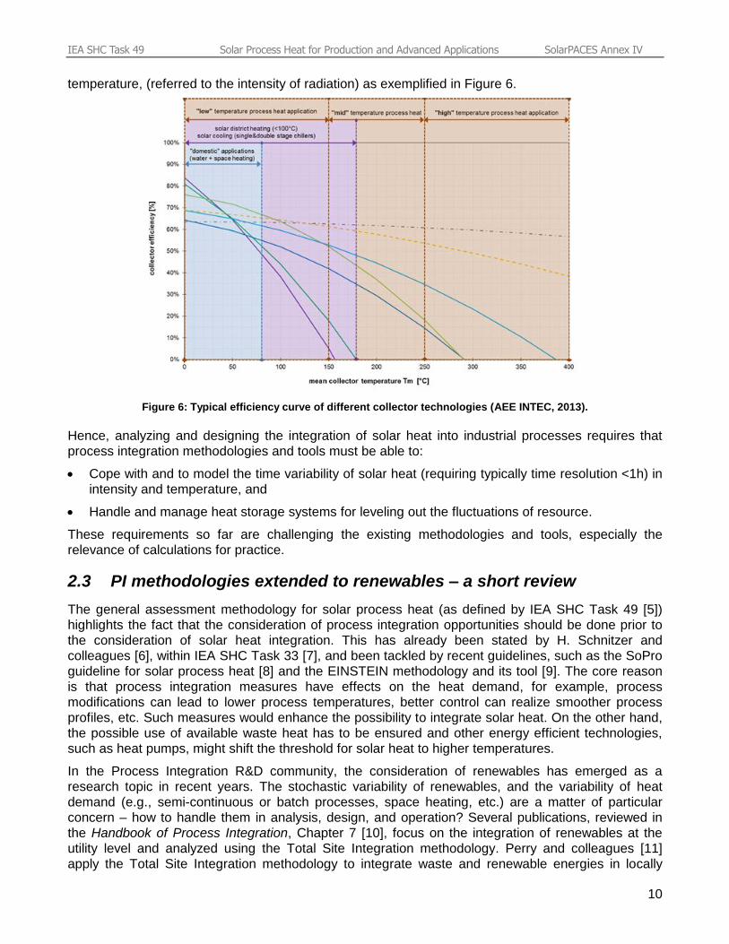
temperature, (referred to the intensity of radiation) as exemplified in Figure 6.
Figure 6: Typical efficiency curve of different collector technologies (AEE INTEC, 2013).
Hence, analyzing and designing the integration of solar heat into industrial processes requires that
process integration methodologies and tools must be able to:
Cope with and to model the time variability of solar heat (requiring typically time resolution <1h) in
intensity and temperature, and
Handle and manage heat storage systems for leveling out the fluctuations of resource.
These requirements so far are challenging the existing methodologies and tools, especially the
relevance of calculations for practice.
2.3 PI methodologies extended to renewables – a short review
The general assessment methodology for solar process heat (as defined by IEA SHC Task 49 [5])
highlights the fact that the consideration of process integration opportunities should be done prior to
the consideration of solar heat integration. This has already been stated by H. Schnitzer and
colleagues [6], within IEA SHC Task 33 [7], and been tackled by recent guidelines, such as the SoPro
guideline for solar process heat [8] and the EINSTEIN methodology and its tool [9]. The core reason
is that process integration measures have effects on the heat demand, for example, process
modifications can lead to lower process temperatures, better control can realize smoother process
profiles, etc. Such measures would enhance the possibility to integrate solar heat. On the other hand,
the possible use of available waste heat has to be ensured and other energy efficient technologies,
such as heat pumps, might shift the threshold for solar heat to higher temperatures.
In the Process Integration R&D community, the consideration of renewables has emerged as a
research topic in recent years. The stochastic variability of renewables, and the variability of heat
demand (e.g., semi-continuous or batch processes, space heating, etc.) are a matter of particular
concern – how to handle them in analysis, design, and operation? Several publications, reviewed in
the Handbook of Process Integration, Chapter 7 [10], focus on the integration of renewables at the
utility level and analyzed using the Total Site Integration methodology. Perry and colleagues [11]
apply the Total Site Integration methodology to integrate waste and renewable energies in locally
IEA SHC Task 49 Solar Process Heat for Production and Advanced Applications SolarPACES Annex IV
11
integrated energy sectors (LIES) to reduce the carbon footprint of supplied small-scale industrial
plants, domestic, business and social premises. However, the variability of renewables is not
considered.
Varbanov & Klemes [12] propose a methodology for designing and operating energy conversion &
supply systems integrating renewables featuring variable availability, as well as timely variable users.
The Total Site Integration methodology is combined with the Cascade Analysis originally developed
for batch processes, into a Total Site Heat Cascade. The methodology allows for, in particular, the
determination of important targets, such as the upper bound of renewable capture, the lower bound of
fossil fuels consumption, and the upper bound of energy storage. The time variability (of renewable
resources and/or of user demand) is modeled by a set of time slices, a cascade being calculated for
each time slice, considering heat storage that allows cascading heat to a later time slice. The
optimization of heat storage is mentioned as one of several further steps to follow.
Also relevant for the integration of solar heat are publications on the site-wide heat integration
resorting to heat recovery loops (HRL) with heat storage (HS) ([13], [10] Chapter 20). This is
appropriate for low pinch temperature industry sectors (examples are food and beverage sectors) and
large multi-plant sites using large amounts of hot water and operate semi-continuously. As shown by
Walmsley and colleagues [14], the existence of the HRL-HS infrastructure represents an opportunity
to reduce the costs for integrating solar heat, since the HRL-HS costs can be shared for both the heat
recovery between processes and the solar heat distribution. The authors compare two strategies for
designing and operating the HRL-HS system (constant temperature storage (CTS) versus variable
temperature storage (VTS)) for different pinch temperature positions (hot “end” of heat source profile
versus cold “end” of heat sink profile). Results show that the VTS strategy is more cost-effective, in
particular with respect to the integration of solar heat when the pinch between heat source and heat
sink profiles is located at the hot “end” of the heat source profile.
2.4 Overview of solar heat integration modes and concepts
The integration of solar heat into industrial processes may be achieved at two different “levels”:
1. Transfer of solar heat “directly” to individual process heat sinks – referred to as integration of solar
heat “on process level”
2. Transfer of solar heat to the hot utility system (e.g., steam system, superheated water, thermal oil,
etc., and then in cascade to process heat sinks by utility-process heat exchangers) referred to as
integration of solar heat “on supply level.”
Each integration level has its advantages and drawbacks. IEA SHC Task 49’s Integration Guideline
[5] provides a detailed comparison. In short, the integration at the process level allows in general
lower collector operating temperatures. But due to the variability and partially out of phase availability
of solar heat, heat storage is required in most cases and the solar fraction may be limited to the heat
demand of one or of few heat sinks located very close to each other (retrofitting the process heat
supply infrastructure and building a dedicated loop for distributing solar heat would induce significant
investment costs).
Unlike the process level integration, integrating at the supply level is more flexible because the pay off
of the solar plant is much less dependent on possible future changes in individual processes.
Furthermore, this mode can achieve a larger solar fraction with smaller specific costs (due to
potentially smaller heat storage requirements and to the availability of the utility infrastructure for heat
distribution) at the expense of higher operating temperatures.
The supply level integration can apply to two types of networks: solar heat can be fed into the utility
system or into the HRL-HS system (if it already exists or if this type of system is a cost-effective
retrofit option for multi-process indirect heat integration).
IEA SHC Task 49 Solar Process Heat for Production and Advanced Applications SolarPACES Annex IV
12
The integration point is defined as the interface between the solar plant (including solar heat storage)
and the heat sink side (materialized by a heat exchanger transferring solar heat to the heat sink or a
valve / pipe connection if the heat sink media flows in the collector as well).
A systematic classification of the possible integration concepts was developed by B. Schmitt [15] for
the practical integration schemes for both process level and supply level integration. IEA SHC Task
49 report, Integration Guideline, Chapter 6 [5] presents the classification established based on the
following boundary conditions:
Distinction between supply and process level
Heat transfer medium at supply level
Category of heat consumer at process level
Conventional way of heating at process level
In addition, given an integration concept then a solar process heat system concept must be chosen.
IEA SHC Task 49 report, Integration Guideline, Chapter 7 [5] describes the topic, including strategies
and hydraulic designs for collector loop, storage charging, storage interconnection and storage
discharge.
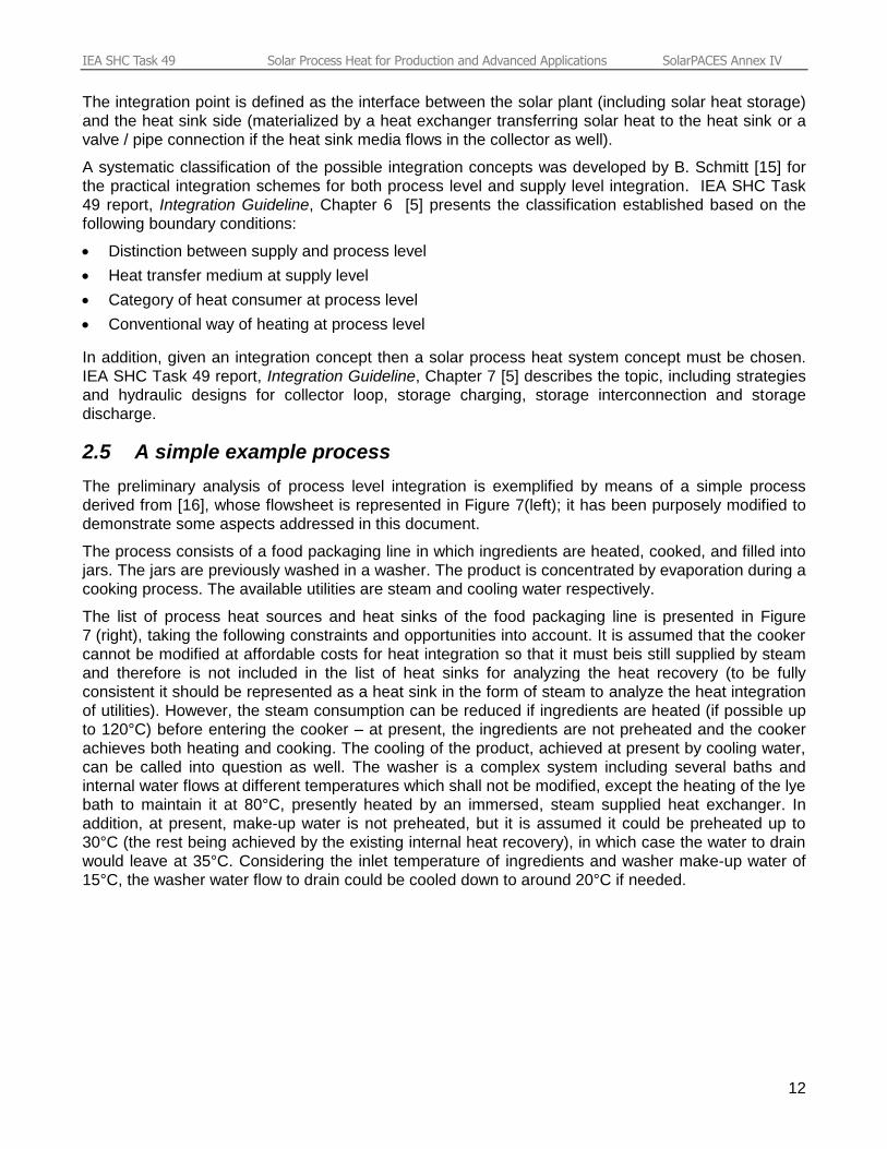
2.5 A simple example process
The preliminary analysis of process level integration is exemplified by means of a simple process
derived from [16], whose flowsheet is represented in Figure 7(left); it has been purposely modified to
demonstrate some aspects addressed in this document.
The process consists of a food packaging line in which ingredients are heated, cooked, and filled into
jars. The jars are previously washed in a washer. The product is concentrated by evaporation during a
cooking process. The available utilities are steam and cooling water respectively.
The list of process heat sources and heat sinks of the food packaging line is presented in Figure
7 (right), taking the following constraints and opportunities into account. It is assumed that the cooker
cannot be modified at affordable costs for heat integration so that it must beis still supplied by steam
and therefore is not included in the list of heat sinks for analyzing the heat recovery (to be fully
consistent it should be represented as a heat sink in the form of steam to analyze the heat integration
of utilities). However, the steam consumption can be reduced if ingredients are heated (if possible up
to 120°C) before entering the cooker – at present, the ingredients are not preheated and the cooker
achieves both heating and cooking. The cooling of the product, achieved at present by cooling water,
can be called into question as well. The washer is a complex system including several baths and
internal water flows at different temperatures which shall not be modified, except the heating of the lye
bath to maintain it at 80°C, presently heated by an immersed, steam supplied heat exchanger. In
addition, at present, make-up water is not preheated, but it is assumed it could be preheated up to
30°C (the rest being achieved by the existing internal heat recovery), in which case the water to drain
would leave at 35°C. Considering the inlet temperature of ingredients and washer make-up water of
15°C, the washer water flow to drain could be cooled down to around 20°C if needed.
IEA SHC Task 49 Solar Process Heat for Production and Advanced Applications SolarPACES Annex IV
13
# Name Tin
[°C]
Tout
[°C]
Flow
[kg/s]
cp
[kJ/kg-1K-1]
Heat rate
[kW]
1 Ingredients heating 15 120 4.0 3.0 1260
2 Product cooling 100 50 3.6 2.778 500
3 Vapour condensation 80 79 0.4 1000 400
4 Washer make-up water 15 30 1.8 4.18 112.86
5 Washer lye bath holding 80 84 17.943 4.18 300
6 Filled jars cooling 45 20 6.0 2.0 300
7 Washer water to drain 35 20 1.5 4.18 94
Figure 7: Process flowsheet (left) and corresponding list of process heat sources and heat sinks (right) of the food
packaging line example process.
2.6 Scoping and screening process integration opportunities
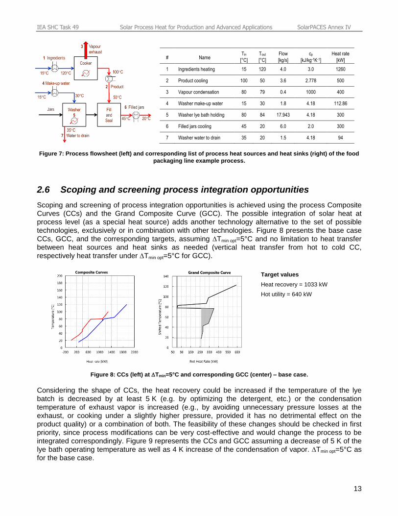
Scoping and screening of process integration opportunities is achieved using the process Composite
Curves (CCs) and the Grand Composite Curve (GCC). The possible integration of solar heat at
process level (as a special heat source) adds another technology alternative to the set of possible
technologies, exclusively or in combination with other technologies. Figure 8 presents the base case
CCs, GCC, and the corresponding targets, assuming Tmin opt=5°C and no limitation to heat transfer
between heat sources and heat sinks as needed (vertical heat transfer from hot to cold CC,
respectively heat transfer under Tmin opt=5°C for GCC).
Target values
Heat recovery = 1033 kW
Hot utility = 640 kW
Figure 8: CCs (left) at Tmin=5°C and corresponding GCC (center) – base case.
Considering the shape of CCs, the heat recovery could be increased if the temperature of the lye
batch is decreased by at least 5 K (e.g. by optimizing the detergent, etc.) or the condensation
temperature of exhaust vapor is increased (e.g., by avoiding unnecessary pressure losses at the
exhaust, or cooking under a slightly higher pressure, provided it has no detrimental effect on the
product quality) or a combination of both. The feasibility of these changes should be checked in first
priority, since process modifications can be very cost-effective and would change the process to be
integrated correspondingly. Figure 9 represents the CCs and GCC assuming a decrease of 5 K of the
lye bath operating temperature as well as 4 K increase of the condensation of vapor. Tmin opt=5°C as
for the base case.
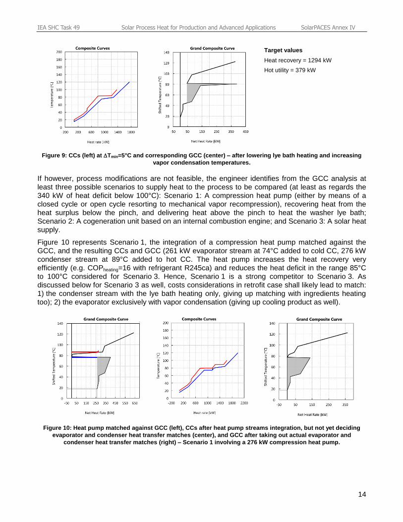
IEA SHC Task 49 Solar Process Heat for Production and Advanced Applications SolarPACES Annex IV
14
Target values
Heat recovery = 1294 kW
Hot utility = 379 kW
Figure 9: CCs (left) at Tmin=5°C and corresponding GCC (center) – after lowering lye bath heating and increasing
vapor condensation temperatures.
If however, process modifications are not feasible, the engineer identifies from the GCC analysis at
least three possible scenarios to supply heat to the process to be compared (at least as regards the
340 kW of heat deficit below 100°C): Scenario 1: A compression heat pump (either by means of a
closed cycle or open cycle resorting to mechanical vapor recompression), recovering heat from the
heat surplus below the pinch, and delivering heat above the pinch to heat the washer lye bath;
Scenario 2: A cogeneration unit based on an internal combustion engine; and Scenario 3: A solar heat
supply.
Figure 10 represents Scenario 1, the integration of a compression heat pump matched against the
GCC, and the resulting CCs and GCC (261 kW evaporator stream at 74°C added to cold CC, 276 kW
condenser stream at 89°C added to hot CC. The heat pump increases the heat recovery very
efficiently (e.g. COPheating=16 with refrigerant R245ca) and reduces the heat deficit in the range 85°C
to 100°C considered for Scenario 3. Hence, Scenario 1 is a strong competitor to Scenario 3. As
discussed below for Scenario 3 as well, costs considerations in retrofit case shall likely lead to match:
1) the condenser stream with the lye bath heating only, giving up matching with ingredients heating
too); 2) the evaporator exclusively with vapor condensation (giving up cooling product as well).
Figure 10: Heat pump matched against GCC (left), CCs after heat pump streams integration, but not yet deciding
evaporator and condenser heat transfer matches (center), and GCC after taking out actual evaporator and
condenser heat transfer matches (right) – Scenario 1 involving a 276 kW compression heat pump.
IEA SHC Task 49 Solar Process Heat for Production and Advanced Applications SolarPACES Annex IV
15
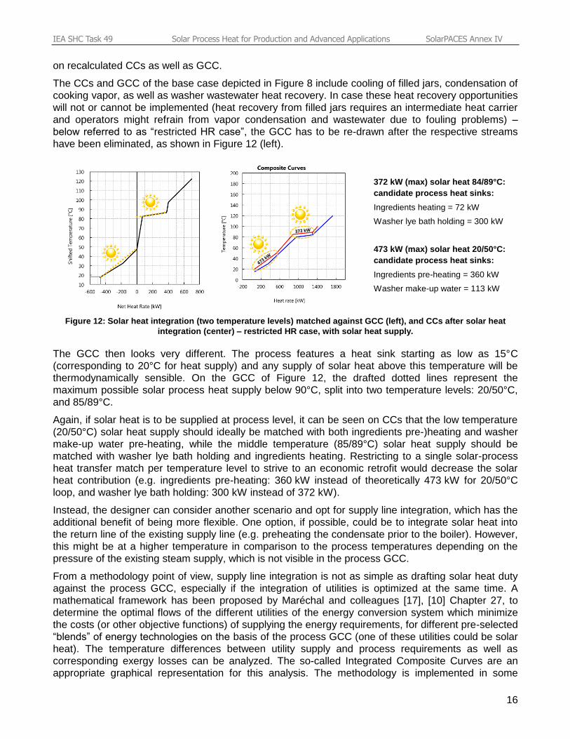
Figure 11 represents Scenario 3, the potential integration of 340 kWaverage 2 solar heat at a
temperature level matched against the GCC (85°C to 100°C) 3. As can be seen on the CCs including
the solar heat source, solar heat should supply both the lye bath holding (300 kW) and ingredients
heating (40 kW) streams. Partial heating of ingredients may not be economical in a retrofit situation 4
so that solar heat contribution should be reduced to 300 kWaverage to achieve a profitable heat
integration with minimum modifications to heat transfer equipment.
Figure 11: Solar heat integration (340 kW) matched against GCC (left), CCs after 340 kW solar heat integration
(center), and GCC after taking out 300 kW solar heat supply actually matched with lye bath (right) – Scenario 3 solar
heat supply.
Ideas for additional scenario may come up during the CCs / GCC / CCs steps therefore, iterations are
often needed to analyze, generate and evaluate the most promising alternatives. Note that the
comparison of scenarios should be based on fully balanced composites (and not partially as done
here for the sake of simplification).
If, for whatever reasons (fouling, distance, temperature control, safety hazard, etc.), some streams
(e.g., waste heat soft streams) are not suitable for heat transfer as implied by the balanced CCs, the
concerned streams must be excluded from the streams list and the heat integration analysis be based
2 kWaverage means design solar heat rate on a sunny sommer day, averaged over the design heat storage period
(typically a day, depending on the variability of heat umbalance between solar supply and heat demand and the
economics of heat storage). 3 Why not size and design the solar plant to supply the whole heat requirement up to 120°C instead? For the
operating temperature, the engineer’s preliminary decision, based on experience, depends on the plant location:
in regions featuring high direct to global radiation ratio, concentrating collector technologies may be used and
high collector operating temperatures can be envisaged a priori, whereas in climatic regions featuring a large
diffuse radiation fraction, the cost-effectiveness of concentrating collector (which make use of direct radiation
only) may be too limited. In the latter case, flat plate collectors are a preferred option, but with the constraint that
the mean collector temperature should be limited to lower values, hence decreasing the average solar heat rate
correspondingly as given by the GCC. Ingredients heating from 80 to 120°C prior to cooker inlet would not be
achieved (either by heat recovery or solar heat) and be heated in the cooker by steam. 4 Almost all SHIP projects so far involve adding a solar heat plant to an existing industrial site. The corresponding
constraints make the search for energy efficient and reasonably cost optimal solutions a complex combinatorial
problem (several process and utility integration alternatives, as well as several integration points for solar heat,
subject to solar plant site specific constraints as well as layout of existing processes and utilities infrastructure).
The Pinch Analysis based methodology allows restricting the search for solar integration to most promising op-
tions while ensuring that other cost-effective alternatives aren’t overlooked. After this preliminary screening of the
appropriate placement of solar heat, several integration points may be analysed and compared with respect to
different criteria, taking practical constraints into account [5].
IEA SHC Task 49 Solar Process Heat for Production and Advanced Applications SolarPACES Annex IV
16
on recalculated CCs as well as GCC.
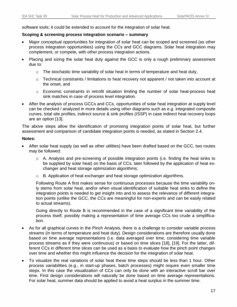
The CCs and GCC of the base case depicted in Figure 8 include cooling of filled jars, condensation of
cooking vapor, as well as washer wastewater heat recovery. In case these heat recovery opportunities
will not or cannot be implemented (heat recovery from filled jars requires an intermediate heat carrier
and operators might refrain from vapor condensation and wastewater due to fouling problems) –
below referred to as “restricted HR case”, the GCC has to be re-drawn after the respective streams
have been eliminated, as shown in Figure 12 (left).
372 kW (max) solar heat 84/89°C:
candidate process heat sinks:
Ingredients heating = 72 kW
Washer lye bath holding = 300 kW
473 kW (max) solar heat 20/50°C:
candidate process heat sinks:
Ingredients pre-heating = 360 kW
Washer make-up water = 113 kW
Figure 12: Solar heat integration (two temperature levels) matched against GCC (left), and CCs after solar heat
integration (center) – restricted HR case, with solar heat supply.
The GCC then looks very different. The process features a heat sink starting as low as 15°C
(corresponding to 20°C for heat supply) and any supply of solar heat above this temperature will be
thermodynamically sensible. On the GCC of Figure 12, the drafted dotted lines represent the
maximum possible solar process heat supply below 90°C, split into two temperature levels: 20/50°C,
and 85/89°C.
Again, if solar heat is to be supplied at process level, it can be seen on CCs that the low temperature
(20/50°C) solar heat supply should ideally be matched with both ingredients pre-)heating and washer
make-up water pre-heating, while the middle temperature (85/89°C) solar heat supply should be
matched with washer lye bath holding and ingredients heating. Restricting to a single solar-process
heat transfer match per temperature level to strive to an economic retrofit would decrease the solar
heat contribution (e.g. ingredients pre-heating: 360 kW instead of theoretically 473 kW for 20/50°C
loop, and washer lye bath holding: 300 kW instead of 372 kW).
Instead, the designer can consider another scenario and opt for supply line integration, which has the
additional benefit of being more flexible. One option, if possible, could be to integrate solar heat into
the return line of the existing supply line (e.g. preheating the condensate prior to the boiler). However,
this might be at a higher temperature in comparison to the process temperatures depending on the
pressure of the existing steam supply, which is not visible in the process GCC.
From a methodology point of view, supply line integration is not as simple as drafting solar heat duty
against the process GCC, especially if the integration of utilities is optimized at the same time. A
mathematical framework has been proposed by Maréchal and colleagues [17], [10] Chapter 27, to
determine the optimal flows of the different utilities of the energy conversion system which minimize
the costs (or other objective functions) of supplying the energy requirements, for different pre-selected
“blends” of energy technologies on the basis of the process GCC (one of these utilities could be solar
heat). The temperature differences between utility supply and process requirements as well as
corresponding exergy losses can be analyzed. The so-called Integrated Composite Curves are an
appropriate graphical representation for this analysis. The methodology is implemented in some
IEA SHC Task 49 Solar Process Heat for Production and Advanced Applications SolarPACES Annex IV
17
software tools; it could be extended to account for the integration of solar heat.
Scoping & screening process integration scenario – summary
Major conceptual opportunities for integration of solar heat can be scoped and screened (as other
process integration opportunities) using the CCs and GCC diagrams. Solar heat integration may
complement, or compete, with other process integration actions.
Placing and sizing the solar heat duty against the GCC is only a rough preliminary assessment
due to:
o The stochastic time variability of solar heat in terms of temperature and heat duty,
o Technical constraints / limitations to heat recovery not apparent / not taken into account at
the onset, and
o Economic constraints in retrofit situation limiting the number of solar heat-process heat
sink matches in case of process level integration.
After the analysis of process GCCs and CCs, opportunities of solar heat integration at supply level
can be checked / analyzed in more details using other diagrams such as e.g. integrated composite
curves, total site profiles, indirect source & sink profiles (ISSP) in case indirect heat recovery loops
are an option [13].
The above steps allow the identification of promising integration points of solar heat, but further
assessment and comparison of candidate integration points is needed, as stated in Section 2.4.
Notes:
After solar heat supply (as well as other utilities) have been drafted based on the GCC, two routes
may be followed:
o A. Analysis and pre-screening of possible integration points (i.e. finding the heat sinks to
be supplied by solar heat) on the basis of CCs, later followed by the application of heat ex-
changer and heat storage optimization algorithms;
o B. Application of heat exchanger and heat storage optimization algorithms.
Following Route A first makes sense for continuous processes because the time variability on-
ly stems from solar heat, and/or when visual identification of suitable heat sinks to define the
integration points is needed to get insight into and to assess the relevance of different integra-
tion points (unlike the GCC, the CCs are meaningful for non-experts and can be easily related
to actual streams).
Going directly to Route B is recommended in the case of a significant time variability of the
process itself, possibly making a representation of time average CCs too crude a simplifica-
tion.
As for all graphical curves in the Pinch Analysis, there is a challenge to consider variable process
streams (in terms of temperature and heat duty). Design considerations are therefore usually done
based on time average representations (i.e. data averaged over time, considering time variable
process streams as if they were continuous) or based on time slices [18], [19]. For the latter, dif-
ferent CCs in different time slices can be used as a basis to evaluate how the pinch point changes
over time and whether this might influence the decision for the integration of solar heat.
To visualize the real variations of solar heat these time steps should be less than 1 hour. Other
process variabilities (e.g., in start-up phases, batch processes) might require even smaller time
steps. In this case the visualization of CCs can only be done with an interactive scroll bar over
time. First design considerations will naturally be done based on time average representations.
For solar heat, summer data should be applied to avoid a heat surplus in the summer time.

IEA SHC Task 49 Solar Process Heat for Production and Advanced Applications SolarPACES Annex IV
18
2.7 Practice relevant HEN & heat storage design
Once Tmin opt has be defined and the CCs are balanced by utilities, the heat integration modeled by
the balanced CCs must be realized by a feasible and cost optimized heat exchanger network (HEN).
During the last 30 years, numerous methods for HEN design have been developed [20], ranging from
design by hand using 2 steps-heuristics, such as the original Pinch Design Method, to automatic
design & optimization using Mathematic Programming (MP) or Evolutionary Algorithm (EA)
techniques to optimize various objective functions, as well as design methods combining insight
provided by Pinch Analysis and MP optimization techniques for their efficient and quick search for
solutions.
For semi-continuous and batch processing, the analysis has so far been mostly divided into time
slices. Few methodologies can actually design HEN for time dependent processes and at the same
time manage heat storage. Heat exchanger and heat storage network design algorithms for variable
process streams are now required and are a strong tool for identifying and comparing process
integration measures, as they translate the thermodynamic potential to practical solutions [21].
For solar process heat design it becomes clear that the tools offered by Pinch Analysis are powerful
for first considerations, however for planning the practical design, it is necessary to consider temporal
variations and possible thermal storage in detail. Here, the designer has to advance from the pure
graphical representation to an optimization-based approach. One possible way to do this is to:
Design a heat exchanger and storage network for waste heat integration with an algorithm
considering the aspect of time,
Analyze the remaining heat demand and subsequently
Re-design this network due to solar process heat integration.
This re-design including solar heat can integrate solar heat as an additional heat source to certain
processes and/or storages based on considerations done via the GCC or CC as discussed above.
Alternatively, a solar heat source can be added as a hot stream and algorithms for heat exchanger
and storage network (HESN) design are activated.
Such algorithms may then suggest solar integration points to achieve highest energy savings at
minimal costs. Based on such combined proposals of heat recovery, solar integration and storage
placement, simple system simulations with adequate tools deliver precise information with only slightly
more effort in comparison with the graphical analysis.
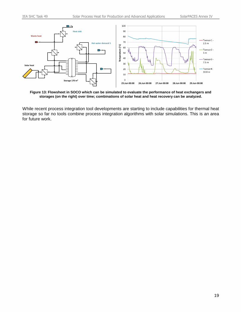
Additionally, parameters such storage sizes and/or operating temperatures can be optimized. Figure
13 shows an exemplary scheme of a heat integration concept including solar heat as utility. System
simulations then allow to design heat exchangers and storages to achieve best performances. These
system simulations include solar heat as a time dependent hot stream (e.g., coming from a solar
simulation tool), however they do not simulate the solar thermal system itself. Such an approach has
been achieved within the SOCO software tool (see Section 3.2).
IEA SHC Task 49 Solar Process Heat for Production and Advanced Applications SolarPACES Annex IV
19
Hot water demand 1
Waste heat
Solar heat
Heat sink
Storage 170 m³
Figure 13: Flowsheet in SOCO which can be simulated to evaluate the performance of heat exchangers and
storages (on the right) over time; combinations of solar heat and heat recovery can be analyzed.
While recent process integration tool developments are starting to include capabilities for thermal heat
storage so far no tools combine process integration algorithms with solar simulations. This is an area
for future work.
IEA SHC Task 49 Solar Process Heat for Production and Advanced Applications SolarPACES Annex IV
20
3 Workflow for integration of solar process heat and process integration software tools
A general methodology for solar heat integration has been set up within the framework of IEA SHC
Task 49 [5], building on the experience of recent R&D projects. It includes nine stages divided into
three main parts: 1) Pre-feasibility assessment, 2) Feasibility study, and 3) Decision making & de-
tailed planning. The workflow presented below covers three stages of part 2, namely: A. Process op-
timization & energy efficiency, B. Identification and ranking of integration points, and C. Analysis of
integration points.
The workflow of the Pinch Analysis based methodology extended to the integration of solar process
heat as previously described, is depicted in a synoptic way in Figure 14 for process level integration
(while the supply level integration, total site integration and integration into heat recovery loops call on
more complex graphical representations and calculation methods). The workflow is to a large extent
iterative for scoping and screening. Each iteration loop includes typically three steps (the so-called
AGE methodology of F. Maréchal):
1. Analysis of heat integration problem (notably using appropriate graphs, often CCs and GCC,
but potentially also other graphs (total site profiles, etc.) depending on the process type and
the issues to be analyzed.
2. Generation of alternative solutions as a result from insight and ideas developed during the
analysis step.
3. Evaluation and comparison of the performances of alternative solutions.
A fourth step could consist of changing/adapting the problem based on the conclusions of the evalua-
tion step.
These steps can essentially be achieved by the engineer manually, for example, based on simplified
models for targeting (if possible), or carried out automatically using optimization algorithms.
The workflow does not represent the following two important input data sets 1) the meteorological,
technical, economical and legal framework conditions and constraints pertaining specifically to the
solar plant (e.g. available area for the solar plant, mechanical load resistance of roofs, subsidies,
fraction of diffuse irradiance, etc.) and 2) the framework conditions and constraints related to the
industrial plant (existing processes and utility networks, plant layout, financing constraints, energy
costs, actual scope for changing some processes, etc.). These opportunities, constraints, and even
“KO-criteria” must be identified from the very beginning since they have a strong influence on the
scope of the process integration analysis.
Integration concepts may vary according to process specifications, existing heat transfer technologies
and options to place additional heat exchangers (e.g. indirect heating vs. direct heating). On the
process side, a systematic classification of integration concepts depending on the type of heat
consumer (process) and the conventional way of heating has been developed in the frame of IEA
Task 49 and of a PhD dissertation by B. Schmitt [15]. On the solar supply side, a classification of solar
process heat system concepts has been defined by A. Helmke and S. Hess [5]. The system concepts
include the following functions of the solar plant towards (but excluding) the integration point: 1)
Collector loop, 2) Charge, 3) Storage and 4) Discharge.
For the analysis of integration points, a list of indicators and a list of criteria have recently been
developed by I. Ben Hassine within the Integration Guideline of the IEA SHC Task 49 [5]. They only
apply once the integration concept and the solar system concept have been defined for each
integration point. The list of quantitative indicators relates to the significance and schedule of the heat
demand, as well as to the resilience to temperature fluctuations, and allows a first evaluation step. A
IEA SHC Task 49 Solar Process Heat for Production and Advanced Applications SolarPACES Annex IV
21
second evaluation step is based on the ranking of integration points with respect to a qualitative
assessment of criteria covering the following families of issues: reliability, cost, benefit, efficiency. The
list of criteria can be seen as a checklist of important issues not to be forgotten.
Concerning the tools implementing part of the workflow, about ten Pinch Analysis based software
tools are available. A description of their scope and features can be found in [22]. The scope of ap-
plicability may be very different, some being sophisticated tools addressing specific problems or sys-
tems, others covering a broader scope, sometimes at the expense of a lower level of computerization
or degree of optimization, or simplified models. A detailed assessment of these tools focusing on their
suitability to address solar heat is still under way in the frame of IEA SHC Task 49. Tools include:
CDU-int, CRYO-int, and DIST-int are specialized tools allowing the simultaneous design and opti-
mization (including heat integration), for new or retrofit, 1) of crude oil distillation systems (CDU-
int), 2) of complex refrigeration systems for low temperature gas processing (CRYO-int), and 3) of
integrated distillation systems (DIST-int).
ASPEN Energy Analyzer, SuperTarget, HEAT-int, and CWB Pinch Analysis are state-of-the-art,
general purpose software tools for the heat integration of continuous processes, for both retrofit
and new design. HEN can be designed and optimized either automatically or interactively. HEAT-
int may interface with SITE-int, a tool for the design and optimization of site-wide utility systems
using total site analysis. Similarly, CWB-Pinch Analysis interfaces with CWB-Total Site Energy
Management.
INTEGRATION and Optimal-Heat are also general purpose heat integration software tools, includ-
ing in particular, advanced techniques and features for automated design and retrofit of existing
processes.
EINSTEIN is a tool kit for thermal energy auditing of industries, including a heat recovery analysis
and design modules for renewable energy systems. It enables a preliminary solar system design
based on the results of process integration and heat exchanger network design. Operating sched-
ules of processes can be defined in details.
OSMOSE is a software platform that manages and allows flowsheet simulators, process integra-
tion tools, databases (process unit operations, technologies, etc.), various solvers, etc., to com-
municate together to simulate, analyze and optimize complex energy systems. The platform is
mainly used for academic R&D purposes.
CERES is an open source software tool, including a database of processing units to model the
processes, and a data base of heat recovery technologies. CERES applies Pinch Analysis with
optimization techniques to find the most efficient / profitable pathway to recover heat, and special
focus on the optimization of utilities including combined chiller-heat pumps, heat pumps, chillers,
organic rankine cycles (ORC), and cogeneration (CHP) units.
PinCH is a general purpose heat integration tool. PinCH supports batch processes and indirect
heat integration with heat storage systems. Affordability, flexibility and ease of use are preferred to
the powerful optimization methodologies of other tools (e.g. no automatic design, no retrofit). It al-
so includes spreadsheet models for quick heat & mass balancing of a selection of unit operations.
SOCO delivers proposals of heat exchanger networks and heat storage optimization concepts. It
allows simulation, design, and optimization of heat integration solutions for time varying processes
(e.g. real measurement data used for simulation, detailed model of heat exchanger and stratified
heat storages).
OBI is a software tool targeted at the optimization of processes under variable operating rates and
batch conditions. The overall HEN design (merging the HEN specific to each operating case) is
generated with one click of a button.
IEA SHC Task 49 Solar Process Heat for Production and Advanced Applications SolarPACES Annex IV
22
Among this (non-exhaustive) list of tools, few tools address time variable heat flows or batch process-
es and heat storage at a practice relevant degree: EINSTEIN, PinCH, SOCO, and OBI. PinCH and
SOCO are described in more details below. These two tools manage time-dependent processes and
heat storage. It is worth noting that so far no single tool implements the whole workflow, and that the
time consuming steps consisting of identification, assessment and screening of integration points are
neither computerized nor provided with automatic data exchange with process integration tools. The-
se are areas of further work.
Scoping and screening of promising alternative solutions resorting to:
q Process modifications
q Modes of heat integration (direct versus indirect, total site, etc.)
q Efficient energy conversion units (heat pumps, cogeneration, …)
q Integration of solar process heat (SHIP)
q Optimisation of utilities
q ...
Process heating & cooling requirements
(hot and cold process streams data)
Analysis tools & diagrams (CCs, GCCs, etc.)
Composites curves Grand composite cuve
Choosing
possible
integration
points
(chapter 4) Analysing
suitable solar
heat integration
concepts
(chapter 5)
Analysing
suitable solar
heat system
concepts
(chapter 6)
Evaluation
and ranking of
integration points
(chapter 7)
Large number of
possible integration
points
Few specificintegration points
with respective solarprocess heat system
concept
Performances assessment, comparison & ranking
Detailed technical design & costing of few alternatives
Heat integration system
(heat exchangers, heat storages,
infrastructure, control)
Solar simulation studies
(ideally combined with other
process integration actions)
Inte
grat
ion
SH
IP
Figure 14: Simplified workflow of the Pinch Analysis based methodology extended to the integration of solar
process heat (exemplified, for sake of simplicity, for process level integration).
IEA SHC Task 49 Solar Process Heat for Production and Advanced Applications SolarPACES Annex IV
23
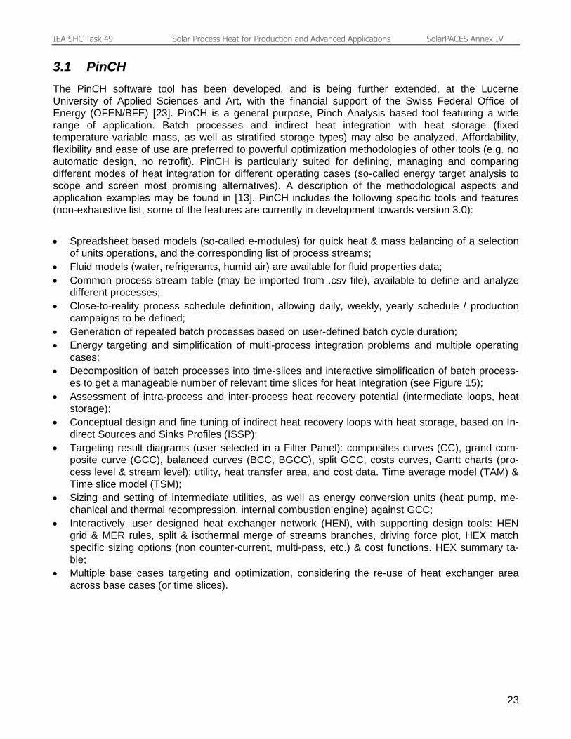
3.1 PinCH
The PinCH software tool has been developed, and is being further extended, at the Lucerne
University of Applied Sciences and Art, with the financial support of the Swiss Federal Office of
Energy (OFEN/BFE) [23]. PinCH is a general purpose, Pinch Analysis based tool featuring a wide
range of application. Batch processes and indirect heat integration with heat storage (fixed
temperature-variable mass, as well as stratified storage types) may also be analyzed. Affordability,
flexibility and ease of use are preferred to powerful optimization methodologies of other tools (e.g. no
automatic design, no retrofit). PinCH is particularly suited for defining, managing and comparing
different modes of heat integration for different operating cases (so-called energy target analysis to
scope and screen most promising alternatives). A description of the methodological aspects and
application examples may be found in [13]. PinCH includes the following specific tools and features
(non-exhaustive list, some of the features are currently in development towards version 3.0):
Spreadsheet based models (so-called e-modules) for quick heat & mass balancing of a selection
of units operations, and the corresponding list of process streams;
Fluid models (water, refrigerants, humid air) are available for fluid properties data;
Common process stream table (may be imported from .csv file), available to define and analyze
different processes;
Close-to-reality process schedule definition, allowing daily, weekly, yearly schedule / production
campaigns to be defined;
Generation of repeated batch processes based on user-defined batch cycle duration;
Energy targeting and simplification of multi-process integration problems and multiple operating
cases;
Decomposition of batch processes into time-slices and interactive simplification of batch process-
es to get a manageable number of relevant time slices for heat integration (see Figure 15);
Assessment of intra-process and inter-process heat recovery potential (intermediate loops, heat
storage);
Conceptual design and fine tuning of indirect heat recovery loops with heat storage, based on In-
direct Sources and Sinks Profiles (ISSP);
Targeting result diagrams (user selected in a Filter Panel): composites curves (CC), grand com-
posite curve (GCC), balanced curves (BCC, BGCC), split GCC, costs curves, Gantt charts (pro-
cess level & stream level); utility, heat transfer area, and cost data. Time average model (TAM) &
Time slice model (TSM);
Sizing and setting of intermediate utilities, as well as energy conversion units (heat pump, me-
chanical and thermal recompression, internal combustion engine) against GCC;
Interactively, user designed heat exchanger network (HEN), with supporting design tools: HEN
grid & MER rules, split & isothermal merge of streams branches, driving force plot, HEX match
specific sizing options (non counter-current, multi-pass, etc.) & cost functions. HEX summary ta-
ble;
Multiple base cases targeting and optimization, considering the re-use of heat exchanger area
across base cases (or time slices).
IEA SHC Task 49 Solar Process Heat for Production and Advanced Applications SolarPACES Annex IV
24
Figure 15: PinCH: screenshot of the Energy Target Analysis interface for simplifying repeated batch processes to
most energy relevant time slices for direct heat recovery.
3.2 SOCO
The SOCO software tool has been developed to bridge the gaps between classical Pinch Analysis
and analyzing the true inter-linkage of heat recovery and solar heat integration in more details, taking
into account time variability and heat storage simulation. The software, of which a detailed description
has been published recently [21], allows Pinch Analysis for time-dependent streams and generation of
heat exchanger and heat storage network considering variable heating and cooling requirements by
an optimization algorithm, as well as corresponding flowsheet simulation.
Time variable process streams can be imported into the tool and the Pinch Analysis is carried out with
time-averaged data, as well as for each time step (seconds, minutes, hours – depending on the user’s
definition). Via a scroll bar the changes of the CCs over time can be visualized. SOCO also includes
an algorithm for proposing heat exchanger placement based on the theoretical potential shown in the
composite curves. As all process streams can be variable, heat storages are suggested as well.
With such first information from the tool algorithms, the user can draw simplified flowsheets of the
heat recovery measures and (if applicable) solar heat integration. In this case solar heat is included as
hot stream in the stream database. The combined effect of heat integration through heat storages can
then be analyzed in a simplified system simulation. The simulation analyses heat transfer in heat
exchangers and storages, however does not include details of piping losses.
For working with SOCO on the food packaging line example process, it was assumed that the cooker
and filler operate at 2 shifts Monday–Friday while the washer operates one shift every weekday.
Assuming that the heat recovery potential can be tapped from all streams, all streams were kept in
the analysis. The algorithm for proposing heat exchangers then suggests integrating hot product flow
leaving the cooker with the incoming ingredients and including the heat generated by vapor
condensation for the unit operation. In this way, the ingredients can be heated to about 72°C.
Some remaining heat of the cooking vapor is suggested for pre-heating the make-up water for the
IEA SHC Task 49 Solar Process Heat for Production and Advanced Applications SolarPACES Annex IV
25
jars washer. Additionally, SOCO suggests using the heat of the filled jars to preheat this water flow.
SOCO does not recommend heating the lye bath using heat recovery, as only the hot product leaving
the cooker would be available in that temperature range, which is preferably for preheating the
incoming ingredients. This is well explained by the criteria in the proposal generation of SOCO, which
is – in addition to the user-defined settings of the importance of power, energy savings and exergy
losses per HEX in the analysis – the similarity in heat capacity flowrate.
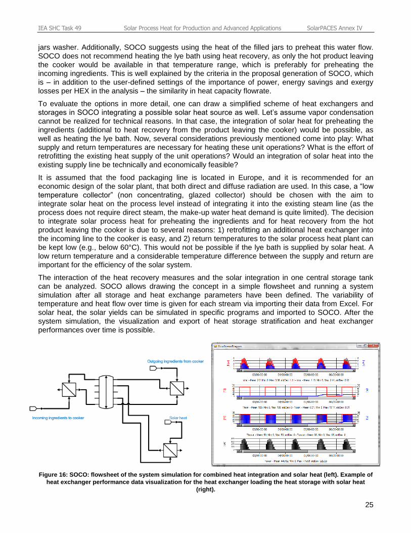
To evaluate the options in more detail, one can draw a simplified scheme of heat exchangers and
storages in SOCO integrating a possible solar heat source as well. Let’s assume vapor condensation
cannot be realized for technical reasons. In that case, the integration of solar heat for preheating the
ingredients (additional to heat recovery from the product leaving the cooker) would be possible, as
well as heating the lye bath. Now, several considerations previously mentioned come into play: What
supply and return temperatures are necessary for heating these unit operations? What is the effort of
retrofitting the existing heat supply of the unit operations? Would an integration of solar heat into the
existing supply line be technically and economically feasible?
It is assumed that the food packaging line is located in Europe, and it is recommended for an
economic design of the solar plant, that both direct and diffuse radiation are used. In this case, a “low
temperature collector” (non concentrating, glazed collector) should be chosen with the aim to
integrate solar heat on the process level instead of integrating it into the existing steam line (as the
process does not require direct steam, the make-up water heat demand is quite limited). The decision
to integrate solar process heat for preheating the ingredients and for heat recovery from the hot
product leaving the cooker is due to several reasons: 1) retrofitting an additional heat exchanger into
the incoming line to the cooker is easy, and 2) return temperatures to the solar process heat plant can
be kept low (e.g., below 60°C). This would not be possible if the lye bath is supplied by solar heat. A
low return temperature and a considerable temperature difference between the supply and return are
important for the efficiency of the solar system.
The interaction of the heat recovery measures and the solar integration in one central storage tank
can be analyzed. SOCO allows drawing the concept in a simple flowsheet and running a system
simulation after all storage and heat exchange parameters have been defined. The variability of
temperature and heat flow over time is given for each stream via importing their data from Excel. For
solar heat, the solar yields can be simulated in specific programs and imported to SOCO. After the
system simulation, the visualization and export of heat storage stratification and heat exchanger
performances over time is possible.
Figure 16: SOCO: flowsheet of the system simulation for combined heat integration and solar heat (left). Example of
heat exchanger performance data visualization for the heat exchanger loading the heat storage with solar heat
(right).
IEA SHC Task 49 Solar Process Heat for Production and Advanced Applications SolarPACES Annex IV
26
4 Conclusions & further work
Achieving the ambitious 80% reduction target of greenhouse gases emissions defined in the EU
“Roadmap for moving to a competitive low carbon economy in 2050” requires both energy efficiency
actions and substitution of fossil fuel by solar heat on a large scale. IEA SHC Task 49 aims at
elaborating and improving methods and tools, and at collecting, preparing and disseminating key
information to get prepared to take up this challenge. The Process Integration framework (and Pinch
Analysis in particular) appears to be best suited for “simultaneously” addressing these two challenging
issues in a systematic way and making sure that the solar process heat does not prevent other cost
effective improvements (e.g., heat recovery, efficient energy conversion technologies, new process
technologies) from being implemented. So far, the benefits and savings potential brought about by
Pinch Analysis are often underestimated, especially in SMEs. Indeed, its efficiency and benefits go far
beyond the usual trend of gaining a green image by “merely” adding a solar plant or resorting to good
housekeeping and best practice actions only.
Framework conditions, technical constraints and degrees of freedom related to the solar plant make
solar plant design a complex problem. In addition, the supply of solar heat must comply with essential
rules of Pinch Analysis: solar heat must be supplied above the heat recovery pinch (i.e. at a
temperature higher than the pinch temperature) and the solar heat rate up to a given temperature
should not exceed the net heat deficit as defined by the grand composite curve (provided the process
heat recovery is possible and cheaper than solar heat). The combination and/or competition of solar
heat with other cost effective improvements increases the number of potentially attractive alternative
solutions to be analyzed and compared. Pinch Analysis allows the scoping and screening of the most
promising alternative solutions. However, the methodologies are primarily established for continuous
processes in grassroots situations (i.e., new plant design), while the integration of solar heat requires
time variability of heat flows and heat storage to be tackled, and essentially concerns retrofit projects
(i.e., integration in an existing infrastructure). Although methodologies for batch processes and retrofit
problems exist, few software tools (e.g., EINSTEIN, PinCH, SOCO, and OBI) provide the engineer
with practical features for these issues and help with the heat storage placement and design. Despite
attempts of these tools (especially PinCH and SOCO) further progress is needed, most notably in the
following areas: 1) consideration of retrofit constraints in the determination of the possible alternatives
and the placement of solar heat, 2) methodology developments for the supply level integration and
total site integration of solar heat, and implementation of methodology into software tools, 3) analysis
and design of variable heat flows and heat storage, and 4) computerization of assessment and
comparison of alternative solutions to speed up and simplify their screening. An alternative to the
present manual data exchange between process integration tools and solar simulation tools would be
to introduce simplified models of solar collectors as a special hot utility and interfacing with
meteorological data or to provide interfaces with solar simulation tools into Process Integration tools.
These enhancements would improve the chances to bridge the gaps between solar plant design and
process integration and get the most out the synergies of both fields.
ACKNOWLEDGMENT
Financial support from the Swiss Federal Office of Energy (OFEN/BFE) and the Austrian Ministry of
Transport, Innovation and Technology (BMVIT/FFG) is gratefully acknowledged. The authors are also
grateful to all the IEA SHC Task 49 participants for their willingness to exchange ideas and share ex-
pertise. Chapter 1.1 provided by Wolfgang Glatzl of AEE INTEC.
IEA SHC Task 49 Solar Process Heat for Production and Advanced Applications SolarPACES Annex IV
27
5 Literature references
[1] N. Pardo et al., Heat and cooling demand and market perspective, Joint Research Centre – Institute for Energy and
Transport. European Comission, EUR -Scientific and Technical Research series (2012). ISBN 978-92-79-25310-2, doi:
10.2790/56532.
[2] European Commission, http://ec.europa.eu/clima/policies/roadmap/index_en.htm, accessed on June 26, 2014
[3] Pinch Analysis: for the Efficient Use of Energy, Water & Hydrogen, CANMET, Canada, 2003
http://www.nrcan.gc.ca/energy/efficiency/industry/processes/systems-optimization/process-integration/pinch-analysis/5521,
accessed on June 26, 2014 [4] B. Linnhoff, Pinch Analysis – A State-of-the-Art Overview, Trans IChemE, Vol 71, Part A, September 1993 [5] B. Muster-Slawitsch et al., Integration Guideline, deliverable of IEA SHC Task 49 “Solar Process Heat for Product ion and Advanced Applications” (2015). [6] H. Schnitzer et al., Minimizing greenhouse gas emissions through the application of solar thermal energy in industrial processes, Journal of Cleaner Production 15, 1271-1286 (2007) [7] C. Brunner et al., Industrial Process Indicators and Heat Integration in Industries, International Energy Agency, IEA Task 33, J. Research, Graz, Austria, 2008 [8] S. Hess, O. Axel, Solar Process Heat Generation: Guide to Solar Thermal System Design for Selected Industrial Processes, SO-PRO Project, O.Ö. Energiesparverband, Linz, Austria, 2012 [9] H. Schweiger et al., Guide for EINSTEIN thermal energy audits, Barcelona, Spain, 2012 [10] J.J. Klemes (Editor), Handbook of Process Integration (PI) – Minimisation of Energy and Water Use, Waste and Emissions, WPE 61, Woodhead Publishing Limited, ISBN 978-0-85709-593-0, 2013 [11] S. Perry et al., Integrating waste and renewable energy to reduce the carbon footprint of locally integrated energy sectors, Energy 33 (2008), pp. 1489-1497 [12] P.S. Varbanov, J.J. Klemes, Integration and management of renewables into Total Sites with variable supply and demand, Computers & Chemical Engineering 35 (2011), pp. 1815-1826 [13] F. Brunner et al., Einführung in die energetische Prozessintegration mit der Pinch-Methode - Handbuch für die Analyse von kontinuierlichen Prozessen und Batch-Prozessen (in german), Bundesamt für Energie, Bern - Switzerland, 2014 (to be published) [14] M.R.W. Walmsley et al., Integration of Soalr Heating into Heat Recovery Loops using Constant and Variable Temperature Storage, Chemical Engineering Transactions, Vol. 35, 2013 [15] B. Schmitt, Integration of solar heating plants for supply of process heat in industrial companies (in german), PhD Thesis at University of Kassel, Shaker Verlag, Aachen, 2014 [16] R.W. Clayton, Cost reductions in a Creamery identified by a Process Integration study at Express Foods Group, Energy Technology Support Unit (ETSU), Report RD/22/29, September 1987 (available from British Library Document Supply Service, bldss.bl.uk) [17] F. Maréchal, Chapter 3.19.1.8, UNESCO encyclopaedia of life support systems, In: Frangopoulos Ch. And Tsatsaronis G., EOLSS Publishers Co Ltd, Oxford, UK, 2008 [18] I.C. Kemp, Pinch Analysis and Process Integration - A User Guide on Process Integration for the Efficient Use of Energy, Butterworth Heinemann, 2006, pp. 257-287 [19] B. Linnhoff et al., Process integration of batch processes, IChemE Symposium Series, Nr. 109, pp.221-237, 1988 [20] K.C. Furman, N.V. Sahinidis, A Critical Review and Annotated Bibliography for Heat Exchanger Network Synthesis in the 20th Century, Ind. Eng. Chem. Res., 2002, 41 (10), pp. 2335–2370 [21] B. Muster-Slawitsch et al., Application of an advanced Pinch Methodology for the food and drink production, WIREs Energy Environment 3, 2014.
[22] I. Bulatov, Software Tools for the Heat Integration, in: J.J. Klemes (Editor), Handbook of Process Integration (PI) – Minimisation of Energy and Water Use, Waste and Emissions, WPE 61, Woodhead Publishing Limited, ISBN 978-0-85709-593-0, 2013, pp. 1059-1085
[23] Hochschule Luzern Technik & Architektur, PinCH website: http://pinch-analyse.ch/index.php/en/, accessed on June 26,
2014