Embed Size (px)
Citation preview
METHODOLOGY OF THE ASSESSMENT OF THE ABRASIVE TOOL’S ACTIVESURFACE USING LASER SCATTEROMETRY
Wojciech Kapłonek, Czesław Łukianowicz, Krzysztof NadolnyDepartment of Production Engineering, Faculty of Mechanical Engineering, Koszalin University of Technology,
Koszalin, Poland
E-mail: [email protected]
Received May 2011, Accepted October 2011
No. 11-CSME-43, E.I.C. Accession 3283
ABSTRACT
Diagnostics of abrasive tools requires the use of modern measurement techniques whichallows for fast assessment of a surface in order to determine, for example, the degree of its wearor to detect various type of defects. A wide group of optical measurement methods used for thistype of assessment are based on the phenomenon of light scattering. One such method based onimaging and analysis of light scattering from a surface is laser scatterometry. In this paper, byutilizing laser scatterometry supported by image analysis techniques, a proposal for amethodology of assessment of the degree to which smearing of the grinding wheel active surface(GWAS) occurs during the plunge grinding process, was presented and discussed. Select resultsof experimental investigations carried out on bearing steel 100Cr6 were also presented. Theobtained results confirmed the efficacy of the above-mentioned techniques that could be aninteresting alternative to other methods already used in such measurements.
Keywords: abrasive tool; grinding wheel active surface; smear; laser scatterometry; imageprocessing and analysis.
METHODE D’EVALUATION PAR DIFFUSIOMETRIE DE LA SURFACE ACTIVED’UN OUTIL ABRASIF
RESUME
L’examen diagnostique des outils abrasifs exige l’utilisation de techniques modernes demesures qui permettent une evaluation rapide d’une surface pour determiner, par exemple, ledegre d’usure ou pour detecter differents types de defectuosites. Un vaste ensemble de methodesoptiques de mesure utilisees pour ce type d’evaluation sont basees sur le phenomene de ladiffusion de la lumiere. Une des ces methodes basee sur l’imagerie et l’analyse de la diffusion dela lumiere d’une surface est la diffusiometrie par laser. Nous proposons dans cet article,l’utilisation de la diffusiometrie accompagne par des technologies d’analyse d’images, unemethode d’evaluation du degre pendant lequel se produit le lissage de la meule active (GWAS)durant la periode de rectification en plongee. Des resultats selectionnes des investigationsexperimentales performees sur de l’acier a coussinets 100Cr6 sont presentes. Les resultatsobtenus confirment l’efficacite des techniques ci-dessus, qui pourraient etre une alternativeinteressante a d’autres methodes presentement utilisees pour de telles mesures.
Mots-cles : Mots-cles: outilabrasif; surface active d’une meule; lissage; diffusiometrie;traitement et analyse de l’image.
Transactions of the Canadian Society for Mechanical Engineering, Vol. 36, No. 1, 2012 49
1. INTRODUCTION
In modern automated production processes, especially those that enable us to obtainprecisely manufactured surfaces, high-efficiency abrasive machining is used [1–5]. The courseand effects of such a process are largely dependent on the condition of the grinding tool and,to be more precise, on the condition of its active surface. In the case of modern grindingprocesses [2,3,5] the condition of the grinding wheel active surface (GWAS) determines thesuccessful realization of the process and allows us to obtain certain properties in the machineditem. The condition of the GWAS quickly undergoes changes resulting from the occurrence ofa number of phenomena accompanying the abrasive machining process. These phenomena aredifferent in nature, with one of the most undesirable being that of the forming of smears uponthe GWAS.
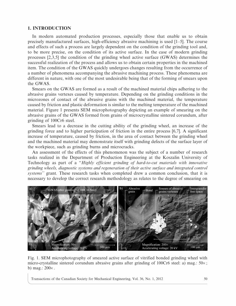
Smears on the GWAS are formed as a result of the machined material chips adhering to theabrasive grains vertexes caused by temperature. Depending on the grinding conditions in themicrozones of contact of the abrasive grains with the machined material, the temperaturecaused by friction and plastic deformation is similar to the melting temperature of the machinedmaterial. Figure 1 presents SEM microphotography depicting an example of smearing on theabrasive grains of the GWAS formed from grains of microcrystalline sintered corundum, aftergrinding of 100Cr6 steel.
Smears lead to a decrease in the cutting ability of the grinding wheel, an increase of thegrinding force and to higher participation of friction in the entire process [6,7]. A significantincrease of temperature, caused by friction, in the area of contact between the grinding wheeland the machined material may demonstrate itself with grinding defects of the surface layer ofthe workpiece, such as grinding burns and microcracks.
An assessment of the effects of this phenomenon was the subject of a number of researchtasks realized in the Department of Production Engineering at the Koszalin University ofTechnology as part of a ‘‘Highly efficient grinding of hard-to-cut materials with innovative
grinding wheels, diagnostic systems and regeneration of their active surface and integrated controlsystems’’ grant. These research tasks when completed drew a common conclusion, that it isnecessary to develop the correct research methodology as relates to the degree of smearing on
Fig. 1. SEM microphotography of smeared active surface of vitrified bonded grinding wheel withmicro-crystalline sintered corundum abrasive grains after grinding of 100Cr6 steel: a) mag.: 506;b) mag.: 2006.
Transactions of the Canadian Society for Mechanical Engineering, Vol. 36, No. 1, 2012 50

the GWAS during, and after, completion of the abrasive machining process. Analysis of theproblem resulted in the drawing of certain assumptions, presented below in Table 1.
The assumptions presented in Table 1 related to two approaches. From the scientific point ofview (case 1 – column A), the only accepted features were those which guaranteed proper analysisof the results of smear creation and resulted in an understanding of the mechanisms of theircreation. This was also related to analysis and selection of the appropriate measuring methodswhich could allow us to obtain the desired effect. As can be observed in column 1 most of thefeatures were accepted, which means that the problem of assessment of the GWAS smears wouldbe considered very wide-ranging in this case. From the technological point of view (case 2 – columnB), the very same problem would be considered in a different way. Should we assume that thedeveloped methodology would be used in industrial conditions, e.g. in-process inspection systems,then the requirements concerning the assessment would not be as high as in the first case. Thisreflects the nature of the in-process inspection, being directed moretoward speed and flexibility ofassessment,rather than toward obtaining the precise values of the selected parameters.
In this paper, the Authors offer a methodology of assessment for the degree of smearing onthe GWAS, using the optical method – laser scatterometry – supported by image analysistechniques. The methodology was realized from a scientific point of view. After adequatemodification, it can also be adjusted for practical usage (diagnostics of the abrasive tools inlaboratory or industrial conditions).
2. METHODS AND TECHNIQUES USED FOR DIAGNOSTICS OF ABRASIVETOOLS
2.1. The General Review of Methods and Techniques Used for Diagnostics of Abrasive ToolsIn the diagnosis of abrasive tools a number of measurement methods are used. The review
and characteristics of these methods was discussed in detail in [8,9]. The general classification
Table 1. Assumptions to develop a methodology of assessing the degree of smearing on the GWAS.
Assumptions category Feature A1 B2
Analysed featuresof the GWAS
Smears macrostructure yes noSmears microstructure yes noGeometrical dimension of the smeared area yes yesPhotometric dimension of the smeared area yes yes
Characteristics of themeasurements
Non-contact method of measuring yes yesMeasurement during movement of object no* yesHigh accuracy and repeatability of measurement yes yes**
Short-time of measurement yes* yesProposed measuringmethods
Macrophotography yes noLight microscopy yes noSEM microscopy yes noLaser scatterometry yes yesStylus profilometry yes noOptical profilometry yes noImage processing and analysis techniques yes yes
Note: 1– from a scientific point of view (scientific research, laboratory measurements),2– from a technological point of view (industrial measurements),*optional, **within defined measuring range.
Transactions of the Canadian Society for Mechanical Engineering, Vol. 36, No. 1, 2012 51

includes contact and non-contact methods.The first group includes mainly stylus profilometry[10], which is used to precisely measure the surface topography of abrasive tools. Due to thedurability of the stylus the contact measurements are usually carried out on grinding wheelswith a relatively smooth surface, made of fine abrasive grains (diamond grinding wheels).
The group of non-contact methods is much wider and includes: optical methods [11] (opticalprofilometry, light microscopy, confocal microscopy), imaging methods [12] (scanning electronmicroscopy, infrared (IR) thermovision, machine vision), pneumatic [13] and acoustic methods[14] (related with acoustic emission and use of ultrasound). This group also include imageprocessing and analysis techniques [15] and methods using the artificial neural networks [16].From the above-mentioned methods the most widely used are optical methods. Many of thesemethods are used in the diagnosis of abrasive tools, including the detection and analysis of thedegree of smearing on the GWAS. In this case one of the most interesting groups of opticalmethods is laser scatterometry.
2.2. The General Characteristics of Optical Methods Based on Imaging and Analysis ofScattered Light
The term scatterometry [17–19] defines a group of optical measurement methods using lightscattering phenomena [20–21]. Light scattering methods often use laser radiation, in such caseswe deal with laser scatterometry [22,23]. The group of light-scattering methods includes: TIS(Total Integrated Scattering) [24], ARS (Angle-Resolved Scattering) [25] and OFT (Optical
Fourier Transform) [26].
One of the above-mentioned method groups are methods described as ARS (Angle-ResolvedScattering) or DS (Differential Scattering) [27]. Allow the assessment of surface irregularities,or detection of their defects, on the basis of a measurement of angle values determining thedirection of propagation of a light wave, which is reflected from the surface. In the classicalapproach, related to the measurement of the angular distribution of the scattered light intensity,the aim is to calculate the values of parameters determining this distribution. Other alternativeapproaches are also used. One of them involves the use of a digital image of scattered lightacquired in a static and dynamic way as well as in its proper computer analysis, usingspecialized computer software. Interpretation of the obtained results can also be used forinferring about the texture parameters and, in some cases, allow the correlation of imageparameters with selected surface texture parameters.
Abrasive tools (grinding wheels) are difficult to assess scatterometrically. A lot depends onwhat they are constructed from (for example, stochastically packed grains bonded by binder).This high heterogeneity structure without a clear directivity of machined grooves causes theincrease in the light scattering phenomenon. This phenomenon is manifest by creating anirregularly shaped image of scattered light upon the observation plan. If the grinding wheelsurface is covered with local smears from the machined material, then assessment possibilitiesare slightly improved. This situation is rather paradoxical because expansion of the smears onthe GWAS rapidly decreases the working efficiency of the tool, whilst simultaneously increasingassessment possibilities. For some, especially smeared areas, the grinding wheel surface will becharacterized by similar reflection properties to those of a typical surface made of metal.Thiswill manifest itself in the creation of a relatively regular image form of scattered light on theobservation plan. Alternate observation of smeared (reflecting and partially scattering the lightwave) and non-smeared (scattering the light wave) fragments, will thus be a typical effectaccompanying tools of this type.
Transactions of the Canadian Society for Mechanical Engineering, Vol. 36, No. 1, 2012 52

3. THE METHODOLOGY OF ASSESSING THE DEGREE OF SMEARING ON THEGWAS
In this Section the most important information concerning the proposed methodology ofassessment of the degree of smearing on the GWAS is presented. The basic feature of thepresentedmethodology is its high universality, due to which it can be used both in scientific works,as well as for practical purposes – in measurement systems operating in laboratory and industrialconditions. The methodology consists of six subsequently realized steps, which allows us to treat itas a module solution to a certain degree. Depending on the application, the steps (modules) areproperly configured. The graphic presentation of subsequent steps is presented in Figs. 2–8. Anassessment of the degree of smearing on a grinding wheel with the technical designation1-35620610-SG/F46K7VTO, after internal cylindrical reciprocal grinding of bearing Steel100Cr6, was the example used. Details concerning grinding conditions are given in Table 2.
Two specific areas of the GWAS are examined, in this case (No. 5 and No. 11 respectively)with and without visible smears of the machined material. It contains an ordered textual andgraphic system consisting of groups of input data (on the left) and a visual presentation ofparticular operations (on the right) performed as part of each step. The input information canbe related to, for example, the type and parameters of the used measurement systems or themethod of image acquisition and processing. Visualization of subsequent operations aresupposed to be a logical complementation of the description, facilitating understanding of thealgorithm of operation at each given step. An important element completing the operation cycleis a group of logical conclusion/decision blocks. They are used to obtain the correctinterpretation of the results of operations at each step and allow for a decision to be maderegarding what kind of measurement/analysis should be carried out in succeeding steps. Theinformation contained in the conclusion/decision blocks are considered in a twofold manner inthis methodology, i.e. from ascientific and technological point of view.
3.1. Step I – Acquisition, Processing and Visual Analysis of Macrophotography of the GWASThe first step of the methodology involved a set of operations related to the acquisition,
processing and analysis ofthe macrophotography of the GWAS. This step allowed theattainment of output macrophotography (which was amosaic of 14 single images after stitching)of the grinding wheel surface, which in turn allowed for a visual analysis after development. Itmade identification of the areas of the GWAS which were smeared possible, with preliminarydetermination of their position and geometric dimensions. Acquisition of the grinding wheelsurface images was carried out with a Camedia C-5060WZ digital camera produced byOlympus Corp. (Japan). The camera was placed on a tripod and directed towards the surface ofthe grinding wheel. The acquisition was carried out in the Super Macro mode with manualsetting of the image sharpness. Thedistance between the grinding wheel surface and the lens wasconstant in this mode. All images were acquired within the following parameters: exposure timetexp 5 1/2 s, aperture value F3.0, WB auto, image resolutions 259261944 pixels, ISO speed 100,saving format *.jpg, image quality HQ.
In order to obtain the output GWAS macrophotography after development, 14 single imageshad to be acquired and a stitching process carried out upon them. For this purpose, commandsincluded in the Java-based image processing software ImageJ 1.44, developed by W. Rasbandfrom NIH (National Institutes of Health), were used. The output macrophotography was thendivided into 14 zones without smears and with visible smearing from the machined material.This allowed for more precise visual analysis of particular areas.
Transactions of the Canadian Society for Mechanical Engineering, Vol. 36, No. 1, 2012 53
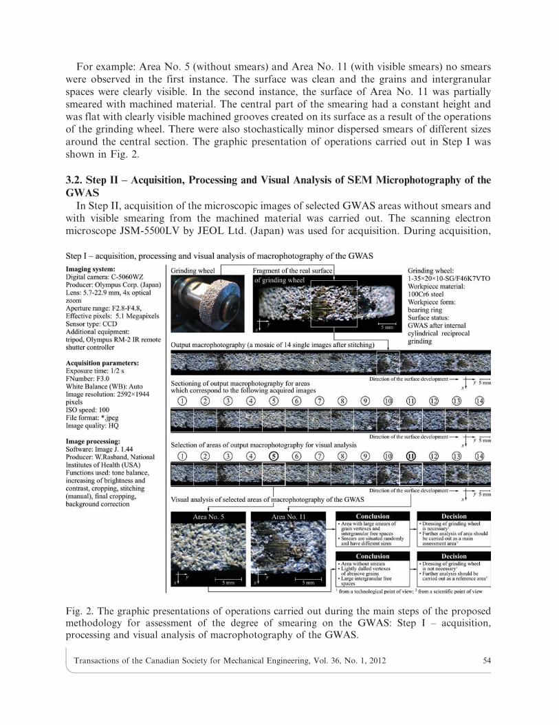
For example: Area No. 5 (without smears) and Area No. 11 (with visible smears) no smearswere observed in the first instance. The surface was clean and the grains and intergranularspaces were clearly visible. In the second instance, the surface of Area No. 11 was partiallysmeared with machined material. The central part of the smearing had a constant height andwas flat with clearly visible machined grooves created on its surface as a result of the operationsof the grinding wheel. There were also stochastically minor dispersed smears of different sizesaround the central section. The graphic presentation of operations carried out in Step I wasshown in Fig. 2.
3.2. Step II – Acquisition, Processing and Visual Analysis of SEM Microphotography of theGWAS
In Step II, acquisition of the microscopic images of selected GWAS areas without smears andwith visible smearing from the machined material was carried out. The scanning electronmicroscope JSM-5500LV by JEOL Ltd. (Japan) was used for acquisition. During acquisition,
Fig. 2. The graphic presentations of operations carried out during the main steps of the proposedmethodology for assessment of the degree of smearing on the GWAS: Step I – acquisition,processing and visual analysis of macrophotography of the GWAS.
Transactions of the Canadian Society for Mechanical Engineering, Vol. 36, No. 1, 2012 54

magnifications of 506, 1006 and 5006 were used, with the accelerating voltage from 15 kV to20 kV. The images were acquired with the following parameters: resolution 12806960 pixels,8-bit color depth, greyscale mode, saving format *.bmp.
For example: In Area No. 5 (without smears) and Area No. 11 (with visible smears) onlymicrochips of the machined material were observed in the first instance. The openness of thestructure of the grinding wheel characterized by relatively large intergranular free spaces zoneswas clearly visible in this area. No signs of the GWAS wearing off, such as blunting ormicrosmears of the abrasive grain vertexes were noticed. In the second instance, in Area No. 11,
Fig. 3. The graphic presentations of operations carried out during the main steps of the proposedmethodology for assessment of the degree of smearing on the GWAS: Step II – acquisition,processing and visual analysis of SEM microphotography of the GWAS.
Fig. 4. The methodology for the acquisition of images of scattered light: a) microphotography of theGWAS with select area for which images of the scattered light were acquired, b) fragment ofmacrophotography of the GWAS with single select area, c) single select area with marked points,d) image of the scattered light acquired for single point.
Transactions of the Canadian Society for Mechanical Engineering, Vol. 36, No. 1, 2012 55

extensive smearing with the machined material was visible. These smears included both theabrasive grains vertexes, as well as the intergranular free spaces. In SEM microphotographschips of the machined material were also visible. The chips under the influence of hightemperatures, caused by friction in this area, melted into the smearing mass, causing an increasein smearing. The graphic presentation of operations carried out in Step II are shown in Fig. 3.
3.3. Step III – Acquisition, Processing and Visual Analysis of Images of Scattered Light(Preliminary Analysis)
The next step of the presented methodology was the acquisition, processing and visualanalysis of the images of angular distribution of the scattered light intensity. The acquisitionwas carried out on a specially constructed experimental set-up. The set-up consisted of twobasic elements: a measuring table with a holder used for mounting the grinding wheel and aholder for mounting the light source on the digital camera. The measuring table was placed ontwo linear translation stages of type KB 11737, produced by Cobrabid (Poland). They wereused for precise manual regulation of the position of the table along the x and y axes. Thedislocation range in both axes was 25 mm with 0.01 mm accuracy. A semiconductor laserCPS180 produced by Thorlabs, Inc. (USA) emitting a constant beam of light from the visiblelight range (wavelength l5635 nm), was placed in the mounting holder for the light source. Thebeam was directed at an angle of 45u and illuminated the surface of the grinding wheel,generating a 1 mm diameter spot on to it. The beam of light incident onto the grinding wheelsurface was reflected and partly scattered, creating an optical image (pattern) of the scatteredlight in the observation plane. The observation plane was a matt screen with a scale forpreliminary calculations of the geometrical dimensions of the generated image.
Fig. 5. The graphic presentations of operations carried out during the main steps of proposedmethodology for assessment of the degree of smearing on the GWAS: Step III – acquisition,processing and visual analysis of images of scattered light (preliminary analysis).
Transactions of the Canadian Society for Mechanical Engineering, Vol. 36, No. 1, 2012 56

Fig. 6. The graphic presentations of operations carried out during the main steps of the proposedmethodology for assessment of the degree of smearing on the GWAS: Step IV – computerprocessing and analysis of images of scattered light (proper analysis).
Transactions of the Canadian Society for Mechanical Engineering, Vol. 36, No. 1, 2012 57
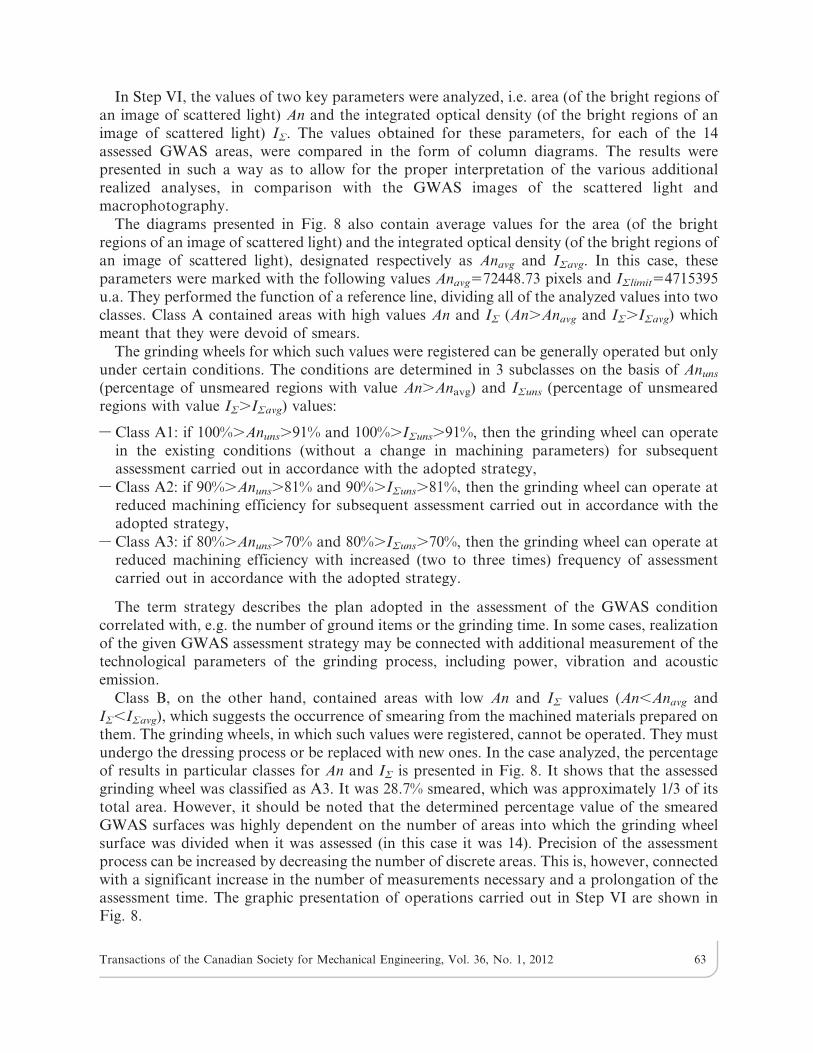
The acquisition was carried out under static conditions for all 14 areas with and withoutvisible smears, when the incidence plane was parallel to the grinding wheel axis. Each area had asize of 565 mm. Within each area 25 images of scattered light, for all points (diameterø51 mm), were acquired.The total number of acquired images for the complete surface of thegrinding wheel was 350. During this process the surface of the grinding wheel was dry. Themethodology for the acquisition of images of scattered light was shown in Fig. 4.
For acquisition of images of scattered a digital camera Camedia C-5060WZ produced byOlympus Corp. (Japan) with remote shutter release RM-2 IR was used. Scattered light imageswere acquired with the following parameters: exposure time texp54 s, aperture value F3.5, WBauto, image resolution 259261944 pixels, ISO speed 400, saving format *.jpg, image qualityHQ.
For example: Area No. 5 (without smears) and Area No. 11 (with visible smears) wide lightscattering without any regularly shaped optical pattern, characteristic of machined surfaces wasobserved in the first instance. In the second instance, for Area No. 11, a zone with a highlyconcentrated light wave reflected from the surface, on which metallic smearing was observed inthe central part of the image. The wave created a clearly visible optical pattern forming afragment of a conic section (circle) with increased light intensity, in contrast to the surface No. 5image. Moreover, numerous peripheral light scatterings were observed. The occurrence of sucheffects meant that the analyzed surface was smeared with the machined material. The graphicpresentation of operations carried out in Step III was shown in Fig. 5.
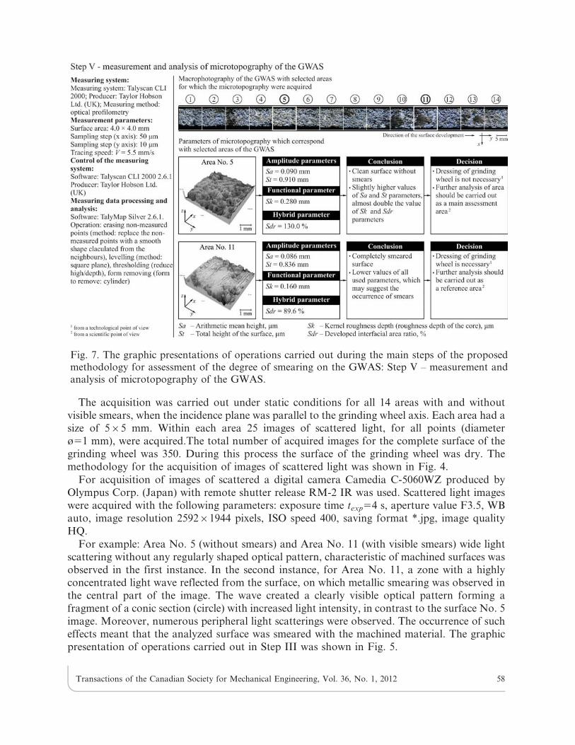
Fig. 7. The graphic presentations of operations carried out during the main steps of the proposedmethodology for assessment of the degree of smearing on the GWAS: Step V – measurement andanalysis of microtopography of the GWAS.
Transactions of the Canadian Society for Mechanical Engineering, Vol. 36, No. 1, 2012 58

3.4. Step IV – Computer Processing and Analysis of Images of Scattered Light (Proper Analysis)Step IV of this methodology assumed processing and analysis of the acquired images of the
angular distribution of the scattered light. For this purpose commercial scientific software,produced by Media Cybernetics, Inc. (USA), called Image-Pro Plus (version 5.1.0.20) was used.The analysis included determining the values of selected geometrical and photometricalparameters of the assessed images whose characteristics are presented in Table 3.
From each group of parameters the so-called key parameters were selected, i.e. those whichmost fully represented features of the analyzed images of scattered light. The values of theseparameters had the largest influence on the results and proper interpretation of the analysis.The parameters were as follows:
– area (of the bright regions of an image of scattered light) – geometrical parameter,
– integrated optical density (of the bright regions of an image of scattered light) –photometrical parameter.
When the parameters, whose numerical values had to be calculated, were determined, theimage processing began. The software segmented particular images (in order to obtain the
Fig. 8. The graphic presentations of operations carried out during the main steps of the proposedmethodology for assessment of the degree of smearing on the GWAS: Step VI – final interpretation.
Transactions of the Canadian Society for Mechanical Engineering, Vol. 36, No. 1, 2012 59

contours necessary for determining the geometrical parameters) or conducted tonal correction(improving the brightness and contrast in order to obtain the correct photometric parametervalues). Regardless of the method of preliminary processing of the images, the above-mentionedparameters were obtained using the Count/Size command. It allowed for a quantity analysis inthe automatic mode to be carried out. On the basis of the number of counted objects, thesoftware determined the values of the required parameters.
For example: Area No. 5 (without smears) and Area No. 11 (with visible smears) hadrelatively high values of An and IS parameters, which resulted from lack of smears visible in thisarea, and meant a wider range of light scattering was observed in the first instance. In thesecond instance, for Area No.11, lower values of An and IS were observed, which were acharacteristic feature of a surface smeared with machined material. The image of the scatteredlight of such a surface was characterized by the occurrence of optical effects described before inSection 2.3. The graphic presentation of operations carried out in Step IV are shown in Fig. 6.
3.5. Step V – Measurements and Analysis of Microtopography of the GWASIn Step V the results of the measurements of the GWAS, which had been previously obtained
in Step IV, were extended and completed. In this case, additional measurements were carriedout. The optical profilometry method was used as a reference method. This method allowed thecapturing of a microtopography of the GWAS, and more specifically the areas with, or without,visible smears. Measurements were carried out primarily to determine the surface textureparameters, which showed highest sensitivity to changes in the surface features, caused by theformation of smears. From anumber of determined surface texture parameters only four werechosen: arithmetic mean high Sa, total height of the surface St, kernel roughness depth Sk anddeveloped interfacial area ratio Sdr. All of these parameters are normalized [13]. Their generalcharacteristics are presented in Table 4.
Table 2. Grinding and dressing conditions.
Grinding wheel: 1-35620610-SG/F46K7VTO
Grinding machine: Universal grinding machine RUP 28P equipped withelectro-spindle EV-70/70-2WB type by Fischer AG(Switzerland) (maximum rpm 60 000 min-1, power 5.2 kW)
Dresser: Single-grain diamond dresser with mass Qd51.25 krDressing parameters: nsd 5 12 000 rpm
vfd 5 10 mm/saed 5 0.0125 mm
Grinding parameters: vs 5 60 m/svw 5 0.75 m/sae 5 0.0125 mmae tot 5 0.20 mm (total machiningallowance on workpiece)vfa 5 20 mm/sVw 5 4761 mm3(20 workpieces)
Coolant: 5% water solution of Syntilo RHS oil by Castrol (UK),which was brought into the grinding zone using theflooding method with the rate QC53.0 l/min
Transactions of the Canadian Society for Mechanical Engineering, Vol. 36, No. 1, 2012 60

The measurements were carried out by optical profilometer Talysurf CLI 2000 produced byTaylor Hobson Ltd. (UK). The non-contact instrument, was equipped with a laser measuringhead using an ultra-accurate CCD laser displacement sensor LK-031 (laser light spot 30 mm,measuring range: 30¡5 mm) produced by Keyence Corp. (USA). All microtopographies of theGWAS were measured using laser triangulation for a 4.064.0 mm surface area. Use of theTalysurf CLI 2000 in the surface microtopography measurements was also presented anddiscussed in [29–30].
For example: Area No. 5 (without smears) and Area No. 11 (with visible smears) hadrelatively high values of the determined parameters (Sa, St, Sk, Sdr) observed in the firstinstance. These values reflected the visual GWAS topography, which was much extended andcompletely devoid of smears. In the second instance, lower values of the above-mentionedparameters were registered for Area No. 11, which meant that smearing with the machinedmaterial took place there. A comparison of the obtained numerical values of the analyzedparameters with the surface topography confirmed this fact. The graphic presentation ofoperations carried out in Step V are shown in Fig. 7.
3.6. Step VI – Final InterpretationThe last step of this methodology involves a comparison of the obtained results and their
final interpretation. The results of the measurements using optical profilometry were treated asadditional data, therefore this methodology focused primarily on results obtained from theanalysis of the scattered light images.
Table 3. The general characteristics of the determined parameters from images of the scattered light.
Group ofparameters
Parameter Designation Unit Interpretation
Geometric Area An pixel Area of each object in image.Size (length) l pixel Feret diameter
(i.e. calliper length) alonga major axis of the object.
Size (width) t pixel Feret diameter(i.e. calliper length) alonga minor axis of object.
Photometric Heterogeneity SF u.a. Fraction of pixels thatdeviate more than a certainrange (10% default) fromthe average intensity.
IntegratedOpticalDensity (IOD)
IS u.a. Integrated Optical Density(or integrated intensity). Alsoequal to Area 6 AverageDensity (or intensity).
Margination M u.a. Relative distribution of objectintensity between the center andmargin, with large values frombrighter centers. A value of 0.33indicates a homogenous object.
Transactions of the Canadian Society for Mechanical Engineering, Vol. 36, No. 1, 2012 61

Table
4.Thegeneralcharacteristics
ofthedetermined
surface
texture
parameters.
Group
ofparameters
Parameter
Designation
Unit
Interpretation
Amplitude
Arithmetic
meanheight
Sa
mmMeanoftheabsolute
values
oftheprofile
heights
measured
from
ameanlineaveraged
over
theprofile.
Totalheight
ofthesurface
St
mmHeightbetweenthehighest
peakandthedeepesthole.
Thisparameter
issupplied
inconform
itywiththe2D
parameters.
Functional
Kernel
roughness
depth
(roughness
depth
ofthecore)
Sk
mmSkistheefficientroughnessof
theprofile.It
istheheightof
theroughnessprofile,without
takinginto
accounttheelevated
peaksortheverydeepholes.
Hybrid
Developed
interfacialarearatio
Sdr
%Thedeveloped
surface
indicates
thecomplexityofthesurface
thanksto
thecomparisonofthecurvilinear
surface
andthesupport
surface.A
completely
flatsurface
willhaveaSdrnear0%.A
complex
surface
willhaveaSdrofsomepercent.
Transactions of the Canadian Society for Mechanical Engineering, Vol. 36, No. 1, 2012 62
In Step VI, the values of two key parameters were analyzed, i.e. area (of the bright regions ofan image of scattered light) An and the integrated optical density (of the bright regions of animage of scattered light) IS. The values obtained for these parameters, for each of the 14assessed GWAS areas, were compared in the form of column diagrams. The results werepresented in such a way as to allow for the proper interpretation of the various additionalrealized analyses, in comparison with the GWAS images of the scattered light andmacrophotography.
The diagrams presented in Fig. 8 also contain average values for the area (of the brightregions of an image of scattered light) and the integrated optical density (of the bright regions ofan image of scattered light), designated respectively as Anavg and ISavg. In this case, theseparameters were marked with the following values Anavg572448.73 pixels and ISlimit54715395u.a. They performed the function of a reference line, dividing all of the analyzed values into twoclasses. Class A contained areas with high values An and IS (An.Anavg and IS.ISavg) whichmeant that they were devoid of smears.
The grinding wheels for which such values were registered can be generally operated but onlyunder certain conditions. The conditions are determined in 3 subclasses on the basis of Anuns(percentage of unsmeared regions with value An.Anavg) and ISuns (percentage of unsmearedregions with value IS.ISavg) values:
– Class A1: if 100%.Anuns.91% and 100%.ISuns.91%, then the grinding wheel can operatein the existing conditions (without a change in machining parameters) for subsequentassessment carried out in accordance with the adopted strategy,
– Class A2: if 90%.Anuns.81% and 90%.ISuns.81%, then the grinding wheel can operate atreduced machining efficiency for subsequent assessment carried out in accordance with theadopted strategy,
– Class A3: if 80%.Anuns.70% and 80%.ISuns.70%, then the grinding wheel can operate atreduced machining efficiency with increased (two to three times) frequency of assessmentcarried out in accordance with the adopted strategy.
The term strategy describes the plan adopted in the assessment of the GWAS conditioncorrelated with, e.g. the number of ground items or the grinding time. In some cases, realizationof the given GWAS assessment strategy may be connected with additional measurement of thetechnological parameters of the grinding process, including power, vibration and acousticemission.
Class B, on the other hand, contained areas with low An and IS values (An,Anavg andIS,ISavg), which suggests the occurrence of smearing from the machined materials prepared onthem. The grinding wheels, in which such values were registered, cannot be operated. They mustundergo the dressing process or be replaced with new ones. In the case analyzed, the percentageof results in particular classes for An and IS is presented in Fig. 8. It shows that the assessedgrinding wheel was classified as A3. It was 28.7% smeared, which was approximately 1/3 of itstotal area. However, it should be noted that the determined percentage value of the smearedGWAS surfaces was highly dependent on the number of areas into which the grinding wheelsurface was divided when it was assessed (in this case it was 14). Precision of the assessmentprocess can be increased by decreasing the number of discrete areas. This is, however, connectedwith a significant increase in the number of measurements necessary and a prolongation of theassessment time. The graphic presentation of operations carried out in Step VI are shown inFig. 8.
Transactions of the Canadian Society for Mechanical Engineering, Vol. 36, No. 1, 2012 63
4. CONCLUSIONS
In modern manufacturing industries there are many unsolved problems, or problems thathave not yet been solved in a sufficiently effective manner, related to the diagnosis of thecondition of abrasive tool surfaces.
In this paper, the Authors considered one of these problems, connected with the formation ofsmears on the GWAS, as a result of coming into contact with machined material. The smearshave a highly negative influence on the course and effects of the grinding process. Therefore, thecrucial issue is the effective assessment of the GWAS, which aims at detecting smears as soon aspossible and at preventing their negative consequences, e.g. through changing the grindingparameters or stopping the process and dressing the grinding wheel.
The methodology presented in this paper offers one proposed solution to the problem ofeffective assessment of the degree of smearing on the GWAS. This methodology is based onimaging and analysis of the scattered light, using laser scatterometry and image processing andanalysis techniques. As the presented results show, the optical method enabled precise smeardetection, locating and recognizing them, as well as analysing them to enable the acquisition ofmore detailed information about the condition of the assessed surface. This information can beused as the basis to put forward proper conclusions and make informed and accurate decisions.
The presented methodology is characterized by high universality, allowing for its use in bothscientific works, as well as in laboratory and industrial practice. The module structure of themethodology enables the selection of proper steps within the realized tasks and allows for theirfree modification. From a scientific point of view, there should be as many steps as possible. Sixsteps were used in the paper – the basic steps (Step III, IV and VI) were supported by additionalsteps (Step I, II and V). The number of steps can be obviously increased depending on theresearch complexity. From a technological point of view, the number of steps should be kept toa minimum. Assuming that the assessment will be carried out in an operating measurementsystem, e.g. in-process inspection, the number of steps is dependent on the type of assessedsurface, the number of parameters and the measurement time.
5. ACKNOWLEDGMENT
Part of this work was supported by the Polish Ministry of Science and Higher Educationunder Grant No. N503 214837. The Authors would like to thank the anonymous reviewer forhis helpful comments and suggestions, which greatly improved the manuscript. The Authorswish to thank also employees of Koszalin University of Technology for their help and supportin selected steps of experimental investigations: Mr. Andrzej Nowicki from Laboratory Team Ifor preparing grinding wheels for tests, Mr. Adam Szpakowicz, MSc, BSc, fromUnconventional HydroJetting Technology Center for the measurement of surface microtopo-graphy of tested grinding wheels and Mr. Ryszard Gritzman from Central Laboratory ofInstitute of Mechatronics, Nanotechnology and Vacuum Technique for acquisition of SEMmicrophotographs.
REFERENCES
1. Rowe, W.B., ‘‘Principles of Modern Grinding Technology,’’ William Andrew Applied SciencePublishers, Burlington, 2009.
2. Webster, J. and Tricard, M., ‘‘Innovations in abrasive products for precision grinding,’’ CIRPAnnals, Vol. 53, No. 2, pp. 597–617, 2004.
Transactions of the Canadian Society for Mechanical Engineering, Vol. 36, No. 1, 2012 64

3. Słowinski, B. and Nadolny, K., ‘‘Effective manufacturing method for automated inside
diameter grinding,’’ Journal of Advanced Mechanical Design, Systems, and Manufacturing,
Vol. 1, No. 4, pp. 472–480, 2007.
4. Nadolny, K. and Plichta, J., ‘‘Possibilities of development in the single-pass internal cylindrical
grinding,’’ Conference on Systems Engineering, Las Vegas, USA, pp. 230–235, August 19–21,
2008.
5. Nadolny, K., Plichta, J., Herman, D. and Słowinski, B., ‘‘Single-pass grinding - an effective
manufacturing method for finishing,’’ Conference on Systems Engineering, Las Vegas, USA,
pp. 236–241, August 19–21, 2008.
6. Xu, X., Yu, Y. and Huang, H., ‘‘Mechanisms of abrasive wear in the grinding of titanium (TC4)
and nickel (K417) alloys,’’ Wear, Vol. 255, pp. 1421–1426, 2003.
7. Jackson, M.J., ‘‘Microscalewear of vitrified abrasive materials,’’ Journal of Materials Science,
Vol. 39, pp. 2131–2143, 2004.
8. Byrne, G., Byrne, Dornfeld, D., Inasaki, I., Ketteler, G., Konig, W. and Teti, R., ‘‘Tool
condition monitoring (TCM) — The status of research and industrial application,’’ CIRP
Annals - Manufacturing Technology, Vol. 44, No. 2, pp. 541–567, 1995.
9. Tonshoff, H.K., Friemuth, T. and Becker, J., ‘‘Process monitoring in grinding,’’ CIRP Annals -
Manufacturing Technology, Vol. 51, No. 2, pp. 551–571, 2002.
10. Butler, D.L., Blunt, L. A., See, B. K., Websterd, J. A. and Stout, K. J., ‘‘The characterisation of
grinding wheels using 3D surface measurement techniques,’’ Journal of Materials Processing
Technology, Vol. 127, No. 2, pp. 234–237, 2002.
11. Yan, L., Rong, Y.M., Jiang, F. and Zhou, Z.X., ‘‘Three-dimension surface characterization of
grinding wheel using white light interferometer,’’ The International Journal of Advanced
Manufacturing Technology, Vol. 55, No. 1–4, pp. 133–141, 2011.
12. Fujimoto, M., et al., ‘‘Characterization of wheel surface topography in cBNgrinding,’’ JSME
International Journal Series C, Vol. 49, No. 1, pp. 106–113, 2006.
13. Furutani, K., Nguyen, T.H., Ohguro, N. and Nakamura, T. ‘‘Automatic compensation for
grinding wheel wear by pressure based in-process measurement in wet grinding,’’ Precision
Engineering, Vol. 27, No. 1, pp. 9–13, 2003.
14. Susic, E. and Grabec, I., ‘‘Characterization of the grinding process by acoustic emission,’’
International Journal of Machine Tools & Manufacture, Vol. 40, pp. 225–238, 2000.
15. Feng, Z. and Chen, X., ‘‘Image processing of the grinding wheel surface,’’ International Journal
of Advanced Manufacturing Technology, Vol. 32, No. 1–2, pp. 452–458, 2007.
16. Hoskokawa, A., Oda, M., Mashita, K., Sakuma, K., Yamada, K. and Ueda, T.,
‘‘Discrimination of grinding wheel surface by means of neural network technique. Studies on
in-process evaluation of grinding wheel surface,’’ Journal of the Japan Society for Precision
Engineering, Vol. 69, No. 2, pp. 258–262, 2003. (in Japanese).
17. Stover, J.C., ‘‘Optical Scattering: Measurement and Analysis,’’ McGraw-Hill, Inc., New York,
1990.
18. Ogilvy, J.A., ‘‘Theory of Wave Scattering from Random Rough Surfaces,’’ Adam Hilger,
Bristol, Philadelphia, New York, 1991.
19. Łukianowicz, C., ‘‘Principles of Surface Roughness Measurements by Light Scattering
Method,’’ Technical University of Koszalin, Koszalin, 2001. (in Polish).
20. Duparee, A., ‘‘Light scattering techniques for the inspection of microcomponents and micro-
structures,’’ Optical Inspection of Microsystems (W. Osten Ed.), CRC Press, New York, 2007.
21. Rao, B.C. and Raj, B., ‘‘Study of engineering surfaces using laser-scattering techniques,’’
SADHANA , 28 pp. 739–761, 2003.
Transactions of the Canadian Society for Mechanical Engineering, Vol. 36, No. 1, 2012 65

22. Baumgart, J.W. and Truckenbrodt, H., ‘‘Scatterometry of honed surfaces,’’ Optical Engineering,Vol. 37, No. 5, pp. 1435–1441, 1998.
23. Kapłonek, W. and Łukianowicz, C., ‘‘Assessment of surface microroughness in movement bylaser scatterometry and image stacking,’’ Przeglad Elektrotechniczny (Electrical Review),Vol. 84, No. 5, pp. 155–160, 2008. (in Polish).
24. Tay, C.J., Wang, S.H., Quan, C. and Ng, C.K., ‘‘Surface roughness measurement of semi-conductor wafers using a modified total integrated scattering model,’’ Optik, Vol. 113, No. 7,pp. 317–321, 2002.
25. Bloomstein, T.M., Hardy, D.E., Gomez, L. and Rothschild, M., ‘‘Angle-resolved scatteringmeasurements of polished surfaces and optical coatings at 157 nm,’’ Proceedings of SPIE,Vol. 5040, pp. 742–752, 2003.
26. Tiena, C.-L., Yanga, H.-M. and Liu, M.-C., ‘‘The measurement of surface roughness of opticalthin films based on fast Fourier transform,’’ Thin Solid Films, Vol. 517, pp. 5110–5115, 2009.
27. Jacobson, R.D., Wilson, S.R., Al-Jumaily, G.A., McNeil, J.R., Bennet, J.M. and Mattsson, L.,‘‘Microstructure characterisation by angle-resolved scatter and comparison to measurementsmade by other techniques,’’ Applied Optics, Vol. 31, No. 10, pp. 1426–1435, 1992.
28. Zhang, Z.M. and Zhu, Q.Z., ‘‘Correlation of angle-resolved light scattering with the microfacetorientation of rough silicon surfaces,’’ Optical Engineering, Vol. 44, No. 7, pp. 073601, 2005.
29. Borkowski, P.J., ‘‘Application of abrasive-water jet technology for material sculpturing,’’Transactions of the Canadian Society for Mechanical Engineering, Vol. 34, No. 3–4, pp. 389–400,2010.
30. Nadolny, K., Kapłonek, W., Łukianowicz, C. and Valıcek, J., ‘‘Laser measurements of surfacetopography of abrasive tools using measurement system CLI 2000,’’ Przeglad Elektrotechniczny(Electrical Review), Vol. 87, No. 9a, 24–27, 2011. (in Polish).
Transactions of the Canadian Society for Mechanical Engineering, Vol. 36, No. 1, 2012 66