Embed Size (px)
Citation preview

Signature Technologies
Methods and application
of In-Die Dimensional
Measurement
for the
SignatureACE® System
Rel. 8/20/99 SAMview , MPMview , SPCview , FeatureView , SA2000™, SA2000™ ,
SAMnet , InSitu®, SignatureACE®, and SmartSAM are registered trademarks of Signature Technologies, Inc., within the United States. All other trademarks are the property of their respective companies.
Copyright 1995, 1996, 1997, 1998, 1999 Signature Technologies, Inc. All Rights Reserved.
No part of the contents of this book may be reproduced (via any means — print, electronic, or other) without the written permission of the publisher.
Printed in the USA
Signature Technologies, Inc. • 13375 Stemmons Frwy., #320 • Dallas, Texas 75234 USA Telephone: (972) 488-9777 • Fax: (972) 488-2924
www.signaturetechnologies.com/
INTRODUCTION: This publication attempts to deal with the growing necessity to make actual dimensional measurements while the workpiece is in the midst of the forming process, and by extension, to use the dimensional information thus gathered to either reject workpieces that are outside established tolerances, OR in more advanced applications, actually re-adjust the tooling to bring the workpiece back within acceptable tolerances. The focus of this writing is more toward the actual acquisition of the measurement than the role played by the Signature Technologies system in displaying/controlling/processing the information. Technical details which are specific to thew SignatureACE® system will be highlited,however. The greatest complication that the user will have to deal with is avoiding the “Garbage in - Garbage out” syndrome. In other words, you MUST have good incoming data before you can come to a valid conclusion. The SignatureACE® is of little practical use if what it displays is not true because of improper measurement technique. One of the first necessities is the establishment of the conditions under which a measurement can be made. Basically, this consists of: 1) Defining the required accuracy of the measurement. If a part must be controlled to +/- 0.05” there’s no sense
installing a laser that reads to 0.00002”. Ideally the measurement system should have an order of magnitude more resolution than the required measurement. Your tolerance spec to +/- 0.05” could be easily verified with a measurement system that resolves to 0.005”.
2) Defining the time available to make a measurement. The response time for the sensor is important. A Scanning
laser sweeps once every 0.016 seconds. At 600 spm, the press will only take 0.1 second to stroke, allowing only 0.05 seconds to feed (with a 180 degree feed cycle). If you are scanning the part as it goes by, a Scanning Laser would only scan the part 3 times as it went by - hardly enough to make anything but a presence or absence decision on MAJOR features.
3) Insuring that space in the tooling to do the measurement is available. How much space is needed will be
determined by the choice of measuring equipment. Buried load cells can be quite small, while a laser measuring system is more bulky, requiring protective covering, and proper mounting apparatus.
4) Insure that the conditions in the measurement area are acceptable. The conditions for an inductive sensor are quite
different that the conditions for a laser. There’s NO sense considering optics if you’re flooding the work area, while magnetic sensors live happily in that environment.
5) Defining the manner whereby the sensors will be applied to the workpiece. The sensors may be able to be
permanently fixed in position, OR they may have to be moved in and out depending on the way the workpiece is handled in the tooling, and the location of the feature to be measured.
There are several different ways to accomplish the measurement: “Inductive” methods such as analog proximity sensors or “eddy current” sensors (actually the same thing) “Capacitive” methods using analog devices that respond to the dielectric constant of the probe environment “Fiber Optic” methods using the reflectance of light back into a fiber optic bundle to sense displacement of a target. “Laser triangulation” methods where the location of an object is sensed in terms of its distance from the laser unit
“Laser interruption” methods where the dimension of the object is sensed in terms of the percentage of the laser beam that is blocked. “Gage Head” methods where normally LVDT (Linear Variable Differential Transformers) are used to directly probe the location of physical features on the work piece. “Air pressure differential” methods where the dimension of the object is sensed by sensing the gap between the workpiece and a calibrated air nozzle. “Inferential measurement” dimensioning methods where part features which can’t be directly measured, can be “inferred” from specific changes in a parameter which varies in relationship to the requirement .
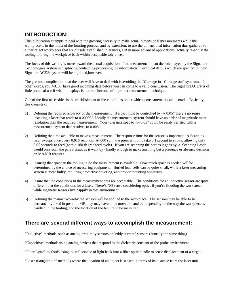
Basic measurement: There are a two different approaches to making a simple measurement - Single Sided, and Differential: Single Sided is potentially less expensive since only ONE measurement system needs to be supplied BUT you must establish a stable PHYSICAL REFERENCE for the measurement - i.e. the part must be positively located before measuring. 1) Physically stabilizing the part to a higher degree than the required measurement accuracy, and applying sensors to
ONE feature of the part (Direct measurement). In the figure below, a magnetic displacement sensor is applied to one side of the part to be measured, while the part is physically referenced by the tool structure. Provision has to be made to ensure that the part is in contact with the reference surfaces.
Figure # 1 - Direct Measurement
2) Differential measurement allows the part to “float” and applies sensors to TWO opposing elements of the part. In
the figure below, the part is monitored by two magnetic displacement sensors where a wider gap at one is compensated for by a narrower gap at the other effectively canceling out horizontal “float” of the part. Since there is a angle involved, the sensors can be calibrated to compensate.
Figure # 2 - Differential Measurement
Obviously in the example above the part must still be stabilized vertically by holding it against the horizontal reference surface. Also, while the part may drift around horizontally without affecting the measurement integrity, it must be constrained to the extent that it doesn’t drift out of the measurement range of the sensors.
In the above examples it could be argued that the angle is not actually being measured. This is true, of course BUT the desired result of the angle (location of the bent portion of the part) is proven. Which system is chosen (direct or differential) is generally related to the possibility or lack thereof of stabilizing the part OR the nature of the required measurement. NOTE: The Slide motion IS NOT stable enough to be used as a reference in any but the coarsest measurements. The
exception is when the measurement is made at B.D.C. and the slide is stabilized through the use of (heavily) loaded stop blocks.
In some cases , the part configuration, and the layout of the tooling will provide intrinsic high accuracy referencing In other cases there’s NO economic way to reference (or even present) the part for measurement, and an external measuring device must be used. When NEW tooling is being designed and built, provision for measurement should be integrated from the start. “REST” stations in progressive tooling provide some of the best measurement opportunities in cases where the critical feature has been finished upstream of the rest station.
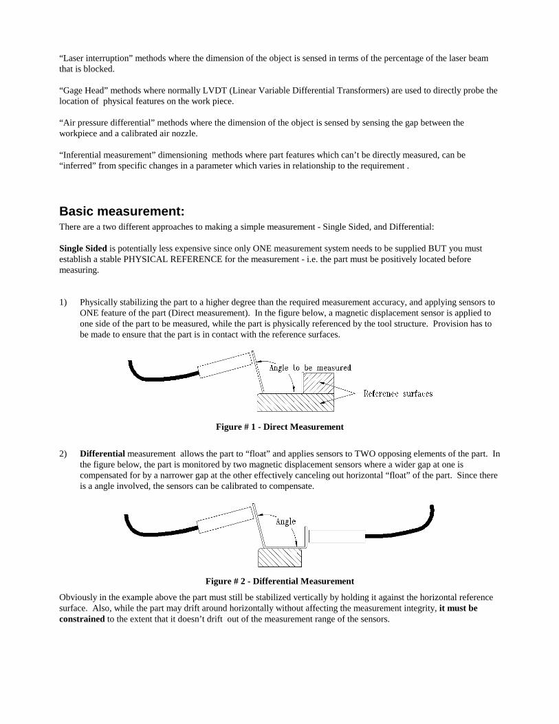
A couple of examples: Part formation: In the case of a shutter for a floppy disc, the part is “U” shaped with two sharp bends.
Figure # 3 - Floppy Shutter Differential Measurement
The sides of the part must wind up in parallel planes with each other, and the dimension between the planes is all important so that the shutter slides smoothly and tightly on the plastic disk body. Whether both bend angles are EXACTLY 90 degrees, is less important than ensuring that the dimension of the shutter at the point farthest from the bend is correct. The part is very fragile, so contact measurement is pretty much out of the question. The dimensional
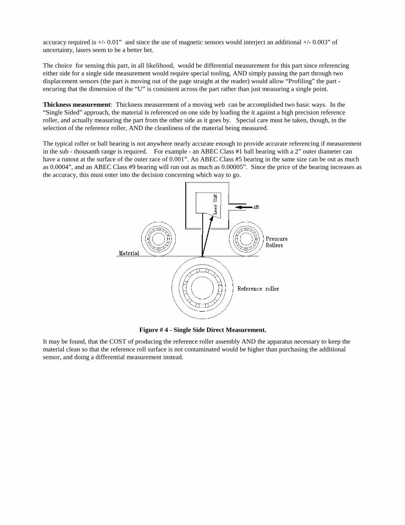
accuracy required is +/- 0.01” and since the use of magnetic sensors would interject an additional +/- 0.003” of uncertainty, lasers seem to be a better bet. The choice for sensing this part, in all likelihood, would be differential measurement for this part since referencing either side for a single side measurement would require special tooling, AND simply passing the part through two displacement sensors (the part is moving out of the page straight at the reader) would allow “Profiling” the part - encuring that the dimension of the “U” is consistent across the part rather than just measuring a single point. Thickness measurement: Thickness measurement of a moving web can be accomplished two basic ways. In the “Single Sided” approach, the material is referenced on one side by loading the it against a high precision reference roller, and actually measuring the part from the other side as it goes by. Special care must be taken, though, in the selection of the reference roller, AND the cleanliness of the material being measured. The typical roller or ball bearing is not anywhere nearly accurate enough to provide accurate referencing if measurement in the sub - thousanth range is required. For example - an ABEC Class #1 ball bearing with a 2” outer diameter can have a runout at the surface of the outer race of 0.001”. An ABEC Class #5 bearing in the same size can be out as much as 0.0004”, and an ABEC Class #9 bearing will run out as much as 0.00005”. Since the price of the bearing increases as the accuracy, this must enter into the decision concerning which way to go.
Figure # 4 - Single Side Direct Measurement.
It may be found, that the COST of producing the reference roller assembly AND the apparatus necessary to keep the material clean so that the reference roll surface is not contaminated would be higher than purchasing the additional sensor, and doing a differential measurement instead.
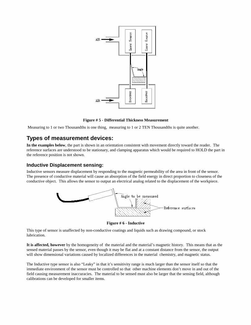
Figure # 5 - Differential Thickness Measurement
Measuring to 1 or two Thousandths is one thing, measuring to 1 or 2 TEN Thousandths is quite another.
Types of measurement devices: In the examples below, the part is shown in an orientation consistent with movement directly toward the reader. The reference surfaces are understood to be stationary, and clamping apparatus which would be required to HOLD the part in the reference position is not shown.
Inductive Displacement sensing: Inductive sensors measure displacement by responding to the magnetic permeability of the area in front of the sensor. The presence of conductive material will cause an absorption of the field energy in direct proportion to closeness of the conductive object. This allows the sensor to output an electrical analog related to the displacement of the workpiece.
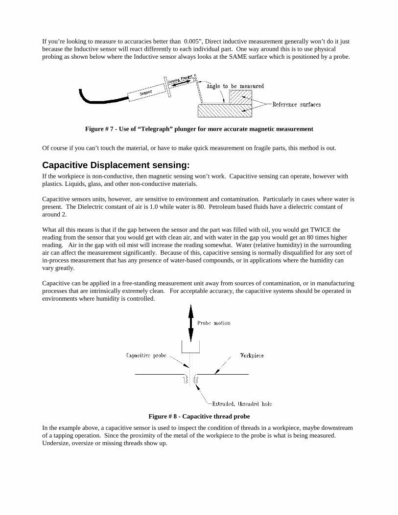
Figure # 6 - Inductive
This type of sensor is unaffected by non-conductive coatings and liquids such as drawing compound, or stock lubrication. It is affected, however by the homogeneity of the material and the material’s magnetic history. This means that as the sensed material passes by the sensor, even though it may be flat and at a constant distance from the sensor, the output will show dimensional variations caused by localized differences in the material chemistry, and magnetic status. The Inductive type sensor is also “Leaky” in that it’s sensitivity range is much larger than the sensor itself so that the immediate environment of the sensor must be controlled so that other machine elements don’t move in and out of the field causing measurement inaccuracies. The material to be sensed must also be larger that the sensing field, although calibrations can be developed for smaller items.
If you’re looking to measure to accuracies better than 0.005”, Direct inductive measurement generally won’t do it just because the Inductive sensor will react differently to each individual part. One way around this is to use physical probing as shown below where the Inductive sensor always looks at the SAME surface which is positioned by a probe.
Figure # 7 - Use of “Telegraph” plunger for more accurate magnetic measurement
Of course if you can’t touch the material, or have to make quick measurement on fragile parts, this method is out.
Capacitive Displacement sensing: If the workpiece is non-conductive, then magnetic sensing won’t work. Capacitive sensing can operate, however with plastics. Liquids, glass, and other non-conductive materials. Capacitive sensors units, however, are sensitive to environment and contamination. Particularly in cases where water is present. The Dielectric constant of air is 1.0 while water is 80. Petroleum based fluids have a dielectric constant of around 2. What all this means is that if the gap between the sensor and the part was filled with oil, you would get TWICE the reading from the sensor that you would get with clean air, and with water in the gap you would get an 80 times higher reading. Air in the gap with oil mist will increase the reading somewhat. Water (relative humidity) in the surrounding air can affect the measurement significantly. Because of this, capacitive sensing is normally disqualified for any sort of in-process measurement that has any presence of water-based compounds, or in applications where the humidity can vary greatly. Capacitive can be applied in a free-standing measurement unit away from sources of contamination, or in manufacturing processes that are intrinsically extremely clean. For acceptable accuracy, the capacitive systems should be operated in environments where humidity is controlled.
Figure # 8 - Capacitive thread probe
In the example above, a capacitive sensor is used to inspect the condition of threads in a workpiece, maybe downstream of a tapping operation. Since the proximity of the metal of the workpiece to the probe is what is being measured. Undersize, oversize or missing threads show up.
Fiber Optic Displacement sensing: The “fiber optic” displacement sensing units are potentially the most sensitive. Resolutions down to 1 angstrom (0.0000001 millimeter - 0.004 microinches) are available. It uses a fiber optic bundle to return light from the target in a manner proportional to the distance to the target. It’s available in either Reflectivity compensated forms where the material passing by has a variable surface finish / color / reflectivity. Or Non-compensated units where you are always looking at the same reflectivity, or the same object. The stand-off distance (distance between the measuring head and the workpiece) is quite small in the higher accuracy versions. They will be confused by liquids on the workpiece, measuring to the surface of the liquid. They will be disabled by dirt and oil collection on the sensor, so are only useable in clean environments. EXCEPTION - if stationary contact with the material is possible. There are Ruby-Tipped units that are sealed, and can measure by direct contact with the workpiece. The contact force is quite high relatively (about 20 ounces of pressure at nominal measuring position).
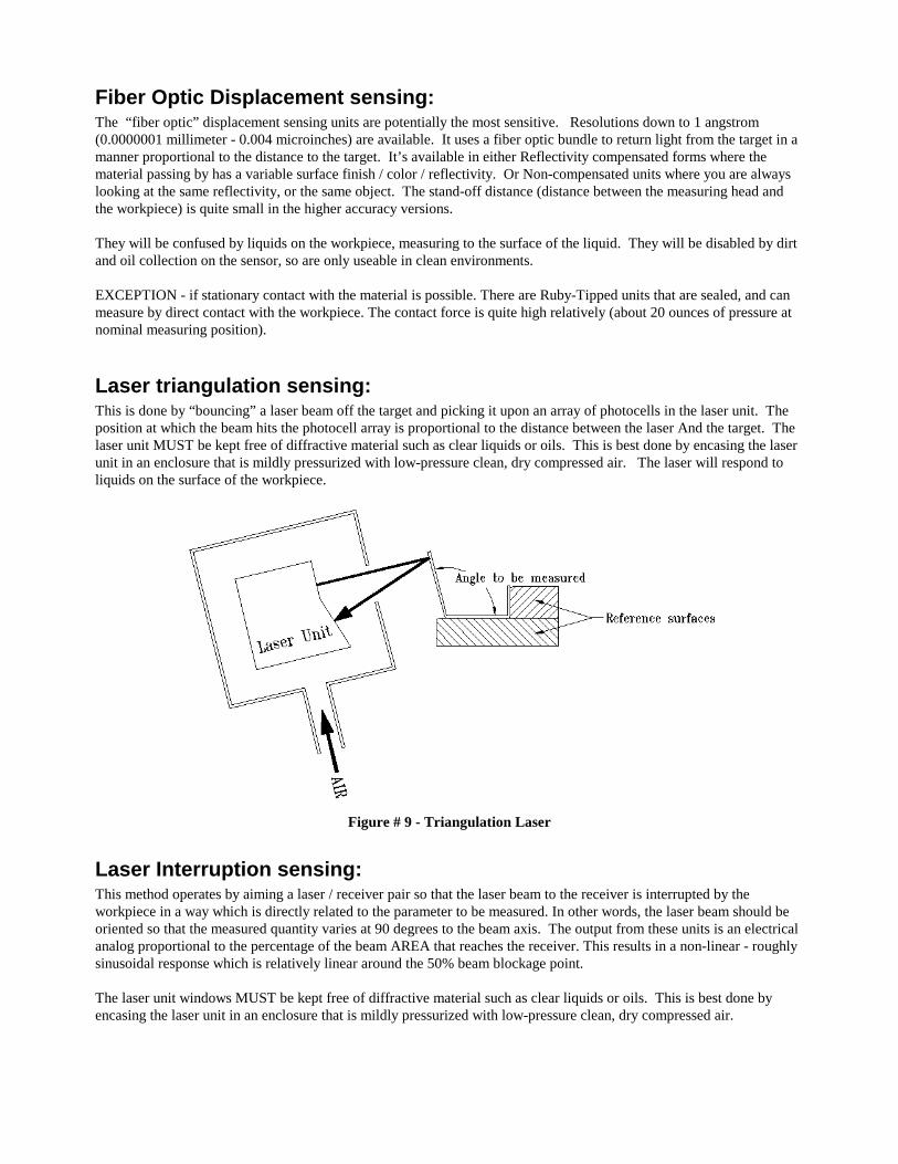
Laser triangulation sensing: This is done by “bouncing” a laser beam off the target and picking it upon an array of photocells in the laser unit. The position at which the beam hits the photocell array is proportional to the distance between the laser And the target. The laser unit MUST be kept free of diffractive material such as clear liquids or oils. This is best done by encasing the laser unit in an enclosure that is mildly pressurized with low-pressure clean, dry compressed air. The laser will respond to liquids on the surface of the workpiece.
Figure # 9 - Triangulation Laser
Laser Interruption sensing: This method operates by aiming a laser / receiver pair so that the laser beam to the receiver is interrupted by the workpiece in a way which is directly related to the parameter to be measured. In other words, the laser beam should be oriented so that the measured quantity varies at 90 degrees to the beam axis. The output from these units is an electrical analog proportional to the percentage of the beam AREA that reaches the receiver. This results in a non-linear - roughly sinusoidal response which is relatively linear around the 50% beam blockage point. The laser unit windows MUST be kept free of diffractive material such as clear liquids or oils. This is best done by encasing the laser unit in an enclosure that is mildly pressurized with low-pressure clean, dry compressed air.
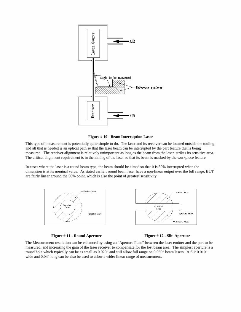
Figure # 10 - Beam Interruption Laser
This type of measurement is potentially quite simple to do. The laser and its receiver can be located outside the tooling and all that is needed is an optical path so that the laser beam can be interrupted by the part feature that is being measured. The receiver alignment is relatively unimportant as long as the beam from the laser strikes its sensitive area. The critical alignment requirement is in the aiming of the laser so that its beam is masked by the workpiece feature. In cases where the laser is a round beam type, the beam should be aimed so that it is 50% interrupted when the dimension is at its nominal value. As stated earlier, round beam laser have a non-linear output over the full range, BUT are fairly linear around the 50% point, which is also the point of greatest sensitivity.
Figure # 11 - Round Aperture Figure # 12 - Slit Aperture
The Measurement resolution can be enhanced by using an “Aperture Plate” between the laser emitter and the part to be measured, and increasing the gain of the laser receiver to compensate for the lost beam area. The simplest aperture is a round hole which typically can be as small as 0.020” and still allow full range on 0.039” beam lasers. A Slit 0.010” wide and 0.04” long can be also be used to allow a wider linear range of measurement.
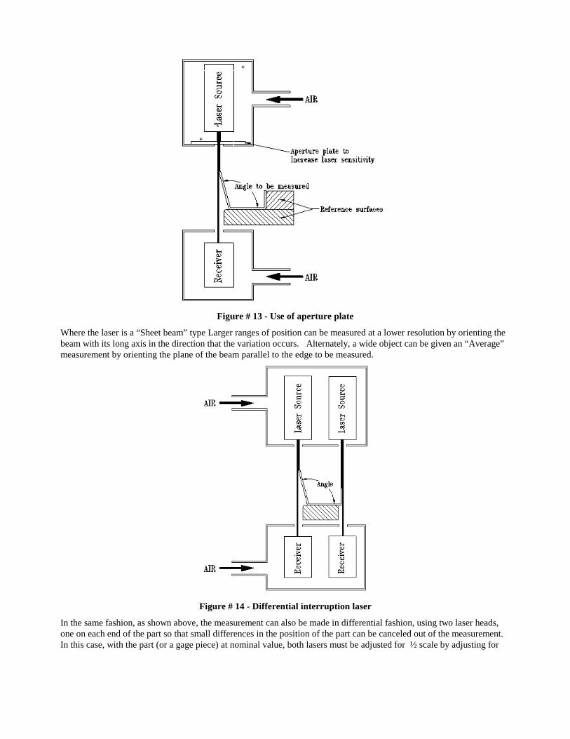
Figure # 13 - Use of aperture plate
Where the laser is a “Sheet beam” type Larger ranges of position can be measured at a lower resolution by orienting the beam with its long axis in the direction that the variation occurs. Alternately, a wide object can be given an “Average” measurement by orienting the plane of the beam parallel to the edge to be measured.
Figure # 14 - Differential interruption laser
In the same fashion, as shown above, the measurement can also be made in differential fashion, using two laser heads, one on each end of the part so that small differences in the position of the part can be canceled out of the measurement. In this case, with the part (or a gage piece) at nominal value, both lasers must be adjusted for ½ scale by adjusting for
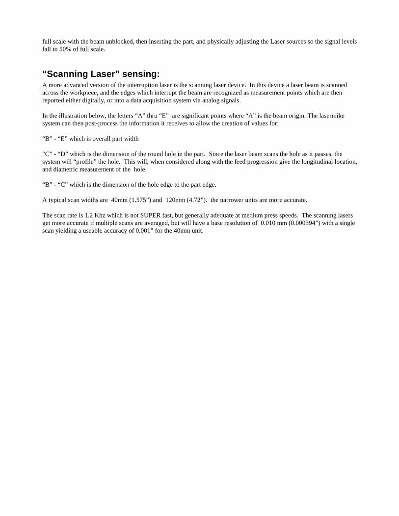
full scale with the beam unblocked, then inserting the part, and physically adjusting the Laser sources so the signal levels fall to 50% of full scale.
“Scanning Laser” sensing: A more advanced version of the interruption laser is the scanning laser device. In this device a laser beam is scanned across the workpiece, and the edges which interrupt the beam are recognized as measurement points which are then reported either digitally, or into a data acquisition system via analog signals. In the illustration below, the letters “A” thru “E” are significant points where “A” is the beam origin. The lasermike system can then post-process the information it receives to allow the creation of values for: “B” - “E” which is overall part width “C” - “D” which is the dimension of the round hole in the part. Since the laser beam scans the hole as it passes, the system will “profile” the hole. This will, when considered along with the feed progression give the longitudinal location, and diametric measurement of the hole. “B” - “C” which is the dimension of the hole edge to the part edge. A typical scan widths are 40mm (1.575”) and 120mm (4.72”). the narrower units are more accurate. The scan rate is 1.2 Khz which is not SUPER fast, but generally adequate at medium press speeds. The scanning lasers get more accurate if multiple scans are averaged, but will have a base resolution of 0.010 mm (0.000394”) with a single scan yielding a useable accuracy of 0.001” for the 40mm unit.
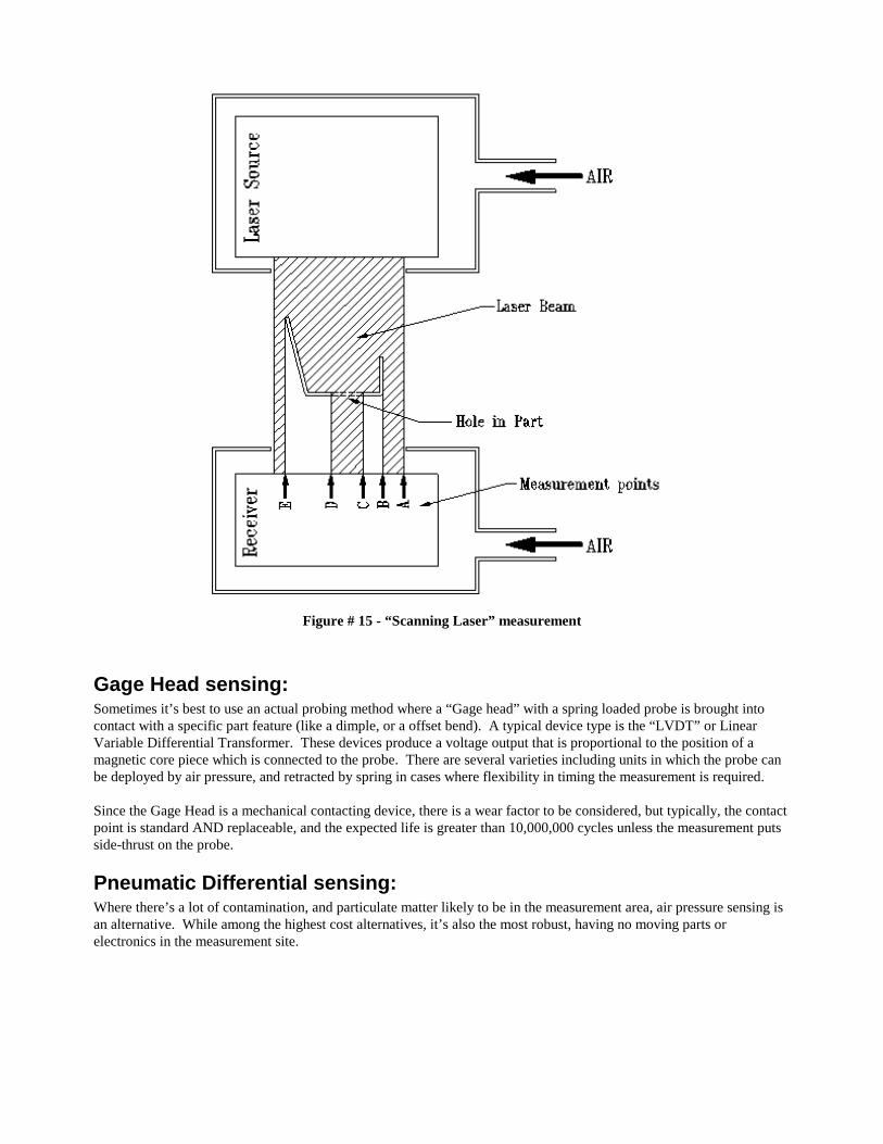
Figure # 15 - “Scanning Laser” measurement
Gage Head sensing: Sometimes it’s best to use an actual probing method where a “Gage head” with a spring loaded probe is brought into contact with a specific part feature (like a dimple, or a offset bend). A typical device type is the “LVDT” or Linear Variable Differential Transformer. These devices produce a voltage output that is proportional to the position of a magnetic core piece which is connected to the probe. There are several varieties including units in which the probe can be deployed by air pressure, and retracted by spring in cases where flexibility in timing the measurement is required. Since the Gage Head is a mechanical contacting device, there is a wear factor to be considered, but typically, the contact point is standard AND replaceable, and the expected life is greater than 10,000,000 cycles unless the measurement puts side-thrust on the probe.
Pneumatic Differential sensing: Where there’s a lot of contamination, and particulate matter likely to be in the measurement area, air pressure sensing is an alternative. While among the highest cost alternatives, it’s also the most robust, having no moving parts or electronics in the measurement site.

Figure # 16 - Pneumatic differential measurement
It’s not the fastest, though requiring as much as 0.3 seconds under worst case to stabilize a measurement from a large step change. Once the workpiece is in position, though, the measurements can be taken at a 0.020 second rate. The readings are accurate to 0.001”. The readings from the pressure sensors being highly non-linear require extensive post-processing to arrive at a linear indication.
Inferential sensing: In cases were there’s NO room to do any implantation of sensors, or where the constraints of the tooling don’t permit access to the part sometimes the measurement can be “Inferential”.
Figure # 17 - Mechanical Reaction Measurement.
Inferential dimension: In the example above, the part to be measured is a “Faston” female connector half. The dimension needed is the distances between the end of the curls, and the back surface of the connector. Since the part CAN be held down against a reference surface, AND there are narrow slots in the back of the connector, we can insert narrow blades. Through the back of the connector and “Infer” the dimension of the curls by the force they apply to the blade tips.
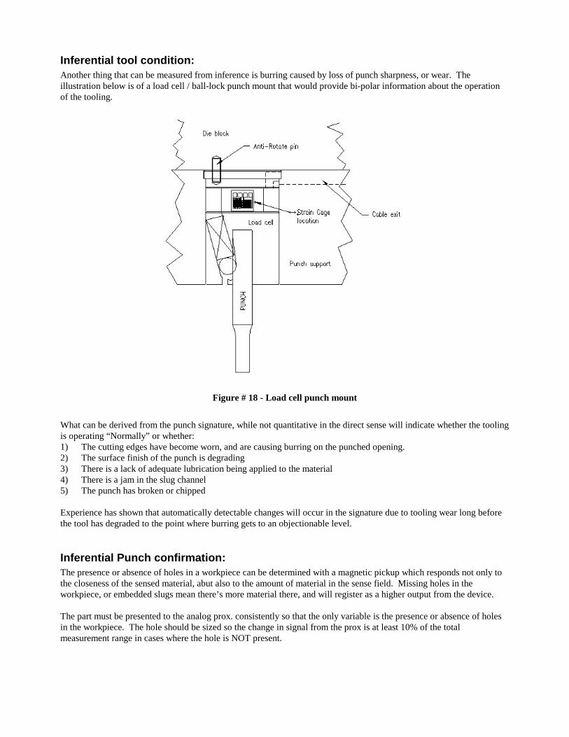
Inferential tool condition: Another thing that can be measured from inference is burring caused by loss of punch sharpness, or wear. The illustration below is of a load cell / ball-lock punch mount that would provide bi-polar information about the operation of the tooling.
Figure # 18 - Load cell punch mount
What can be derived from the punch signature, while not quantitative in the direct sense will indicate whether the tooling is operating “Normally” or whether: 1) The cutting edges have become worn, and are causing burring on the punched opening. 2) The surface finish of the punch is degrading 3) There is a lack of adequate lubrication being applied to the material 4) There is a jam in the slug channel 5) The punch has broken or chipped Experience has shown that automatically detectable changes will occur in the signature due to tooling wear long before the tool has degraded to the point where burring gets to an objectionable level.
Inferential Punch confirmation: The presence or absence of holes in a workpiece can be determined with a magnetic pickup which responds not only to the closeness of the sensed material, abut also to the amount of material in the sense field. Missing holes in the workpiece, or embedded slugs mean there’s more material there, and will register as a higher output from the device. The part must be presented to the analog prox. consistently so that the only variable is the presence or absence of holes in the workpiece. The hole should be sized so the change in signal from the prox is at least 10% of the total measurement range in cases where the hole is NOT present.
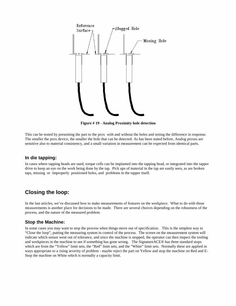
Figure # 19 - Analog Proximity hole detection
This can be tested by presenting the part to the prox with and without the holes and noting the difference in response. The smaller the prox device, the smaller the hole that can be detected. As has been stated before, Analog proxes are sensitive also to material consistency, and a small variation in measurement can be expected from identical parts.
In die tapping: In cases where tapping heads are used, torque cells can be implanted into the tapping head, or integrated into the tapper drive to keep an eye on the work being done by the tap. Pick ups of material in the tap are easily seen, as are broken taps, missing or improperly positioned holes, and problems in the tapper itself.
Closing the loop: In the last articles, we’ve discussed how to make measurements of features on the workpiece. What to do with those measurements is another place for decisions to be made. There are several choices depending on the robustness of the process, and the nature of the measured problem.
Stop the Machine: In some cases you may want to stop the process when things move out of specification. This is the simplest way to “Close the loop”, putting the measuring system in control of the process. The screen on the measurement system will indicate which sensor went out of tolerance, and since the machine is stopped, the operator can then inspect the tooling and workpieces in the machine to see if something has gone wrong. The SignatureACE® has three standard stops which are from the “Yellow” limit sets, the “Red” limit sets, and the “White” limit sets. Normally these are applied in ways appropriate to a rising severity of problem - maybe reject the part on Yellow and stop the machine on Red and E-Stop the machine on White which is normally a capacity limit.
With the SignatureACE® “trending” capability, intrinsic in the “SPCView™ product, you can display the immediate history of the process, then a decision can be made whether the process has actually drifted gradually out of specification, or whether an “anomalous occurrence” is the reason for the stop - something suddenly went wrong. In any case it’s up to the operator or tool setter to figure out what happened. Stopping the process is a good way to apply control where the likelyhood of tooling damage is high when something goes wrong. On the other hand, there are cases where you can’t just stop the machine. Consider the case of a vacuum former for small creamer cups - the machine can’t be stopped with the plastic material in the heating area without causing a much worse problem, so a shut-down protocol may have to be developed in case of recurring workpiece faults. To prevent defects from getting in the “Good parts” bin, other actions may be taken.
Reject the part: In some cases you may want to let the process continue, but segregate the workpieces that don’t appear to be compliant with the specification. In this case the measurement system must have part tracking ability so that when a measurement violation occurs, the offending part can be “tracked” out of the machine to the reject station, and eliminated.
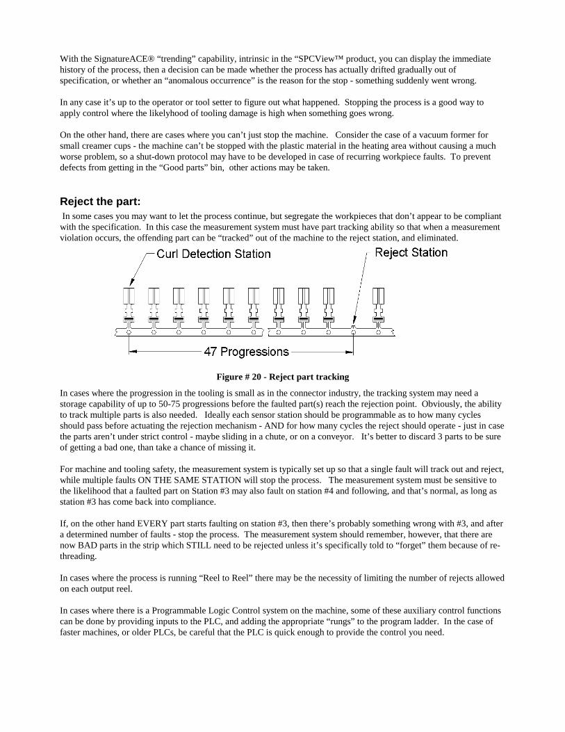
Figure # 20 - Reject part tracking
In cases where the progression in the tooling is small as in the connector industry, the tracking system may need a storage capability of up to 50-75 progressions before the faulted part(s) reach the rejection point. Obviously, the ability to track multiple parts is also needed. Ideally each sensor station should be programmable as to how many cycles should pass before actuating the rejection mechanism - AND for how many cycles the reject should operate - just in case the parts aren’t under strict control - maybe sliding in a chute, or on a conveyor. It’s better to discard 3 parts to be sure of getting a bad one, than take a chance of missing it. For machine and tooling safety, the measurement system is typically set up so that a single fault will track out and reject, while multiple faults ON THE SAME STATION will stop the process. The measurement system must be sensitive to the likelihood that a faulted part on Station #3 may also fault on station #4 and following, and that’s normal, as long as station #3 has come back into compliance. If, on the other hand EVERY part starts faulting on station #3, then there’s probably something wrong with #3, and after a determined number of faults - stop the process. The measurement system should remember, however, that there are now BAD parts in the strip which STILL need to be rejected unless it’s specifically told to “forget” them because of re-threading. In cases where the process is running “Reel to Reel” there may be the necessity of limiting the number of rejects allowed on each output reel. In cases where there is a Programmable Logic Control system on the machine, some of these auxiliary control functions can be done by providing inputs to the PLC, and adding the appropriate “rungs” to the program ladder. In the case of faster machines, or older PLCs, be careful that the PLC is quick enough to provide the control you need.
Automatically Adjust the tooling: The most elegant use of measurement information lies in making the process adaptive. The measurement information in this case is used to control the process so that parts that are drifting toward an out of spec. condition can be automatically adjusted back to nominal values. In cases where the measurement made relates directly to the setting of some portion of the die structure, closed loop adjustment is possible. In these cases, the measurement system can control the adjustment of the tooling in order to correct a changing process. Before this can be done, of course, the machine / tooling must be capable of dynamic adjustment. This is probably the greater part of the application challenge. A typical application of this type of system is the common practice of dynamic shut-height compensation on variable speed machines used in lamination blanking. Since the penetration of the punch into the die button is very slight, the machine shutheight must be set so that the punch separates the slug at low speeds. At high speeds, then, the punch enters too deeply into the die button causing excessive wear from stripping abrasion. A sensor is applied to the face of the ram which monitors the lowest position, and when the ram start coming in deeper due to elevated speeds the shutheight drive “backs off” the adjustment to compensate. This maintains the punch / die button relationship at its optimum value at all speeds. When the machine stops, the system automatically runs the shutheight back to its nominal setting for re-start. The same type of dynamic adjustment can be done within the tooling for bend angle correction, or form heights, or coining pressures, etc. if the die is configured to allow settings to be changed while running. First you MUST confirm the relationship between a measurement, and an associated practical requirement. Case in point: in the can industry, it was found that the depth (or condition within limits) of the score was less important to the proper initiation of a score fracture (opening the can) than the amount of work hardening introduced by coining the initial break area. In this case no amount of measurement or adjustment of the score depth would correct a poor opening condition which was actually caused by insufficient coining pressure three stations earlier.
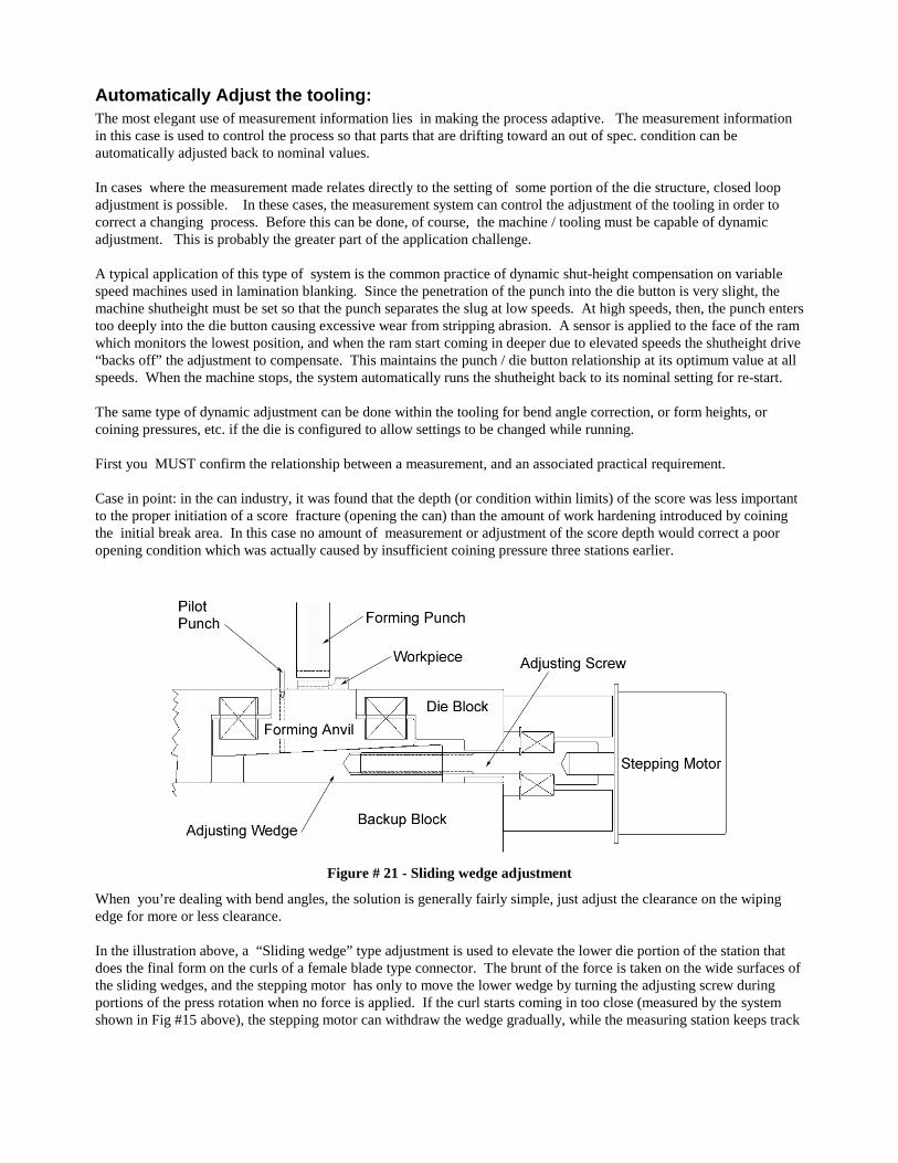
Figure # 21 - Sliding wedge adjustment
When you’re dealing with bend angles, the solution is generally fairly simple, just adjust the clearance on the wiping edge for more or less clearance. In the illustration above, a “Sliding wedge” type adjustment is used to elevate the lower die portion of the station that does the final form on the curls of a female blade type connector. The brunt of the force is taken on the wide surfaces of the sliding wedges, and the stepping motor has only to move the lower wedge by turning the adjusting screw during portions of the press rotation when no force is applied. If the curl starts coming in too close (measured by the system shown in Fig #15 above), the stepping motor can withdraw the wedge gradually, while the measuring station keeps track
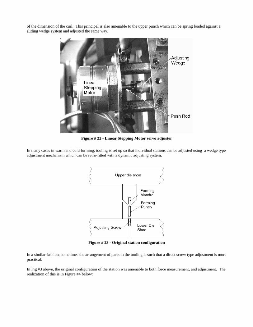
of the dimension of the curl. This principal is also amenable to the upper punch which can be spring loaded against a sliding wedge system and adjusted the same way.
Figure # 22 - Linear Stepping Motor servo adjuster
In many cases in warm and cold forming, tooling is set up so that individual stations can be adjusted using a wedge type adjustment mechanism which can be retro-fitted with a dynamic adjusting system.
Figure # 23 - Original station configuration
In a similar fashion, sometimes the arrangement of parts in the tooling is such that a direct screw type adjustment is more practical. In Fig #3 above, the original configuration of the station was amenable to both force measurement, and adjustment. The realization of this is in Figure #4 below:
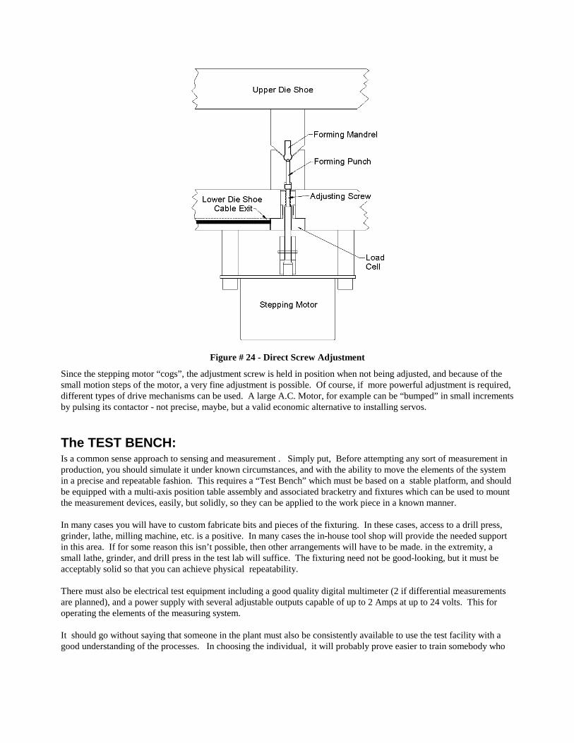
Figure # 24 - Direct Screw Adjustment
Since the stepping motor “cogs”, the adjustment screw is held in position when not being adjusted, and because of the small motion steps of the motor, a very fine adjustment is possible. Of course, if more powerful adjustment is required, different types of drive mechanisms can be used. A large A.C. Motor, for example can be “bumped” in small increments by pulsing its contactor - not precise, maybe, but a valid economic alternative to installing servos.
The TEST BENCH: Is a common sense approach to sensing and measurement . Simply put, Before attempting any sort of measurement in production, you should simulate it under known circumstances, and with the ability to move the elements of the system in a precise and repeatable fashion. This requires a “Test Bench” which must be based on a stable platform, and should be equipped with a multi-axis position table assembly and associated bracketry and fixtures which can be used to mount the measurement devices, easily, but solidly, so they can be applied to the work piece in a known manner. In many cases you will have to custom fabricate bits and pieces of the fixturing. In these cases, access to a drill press, grinder, lathe, milling machine, etc. is a positive. In many cases the in-house tool shop will provide the needed support in this area. If for some reason this isn’t possible, then other arrangements will have to be made. in the extremity, a small lathe, grinder, and drill press in the test lab will suffice. The fixturing need not be good-looking, but it must be acceptably solid so that you can achieve physical repeatability. There must also be electrical test equipment including a good quality digital multimeter (2 if differential measurements are planned), and a power supply with several adjustable outputs capable of up to 2 Amps at up to 24 volts. This for operating the elements of the measuring system. It should go without saying that someone in the plant must also be consistently available to use the test facility with a good understanding of the processes. In choosing the individual, it will probably prove easier to train somebody who
has good mechanical “feel” but no electrical background to use the equipment, that it would be to train an electronic technician with no mechanical “sense” to define the measurements. If you have a skilled diemaker who works with electronics as a hobby, you are truly fortunate.
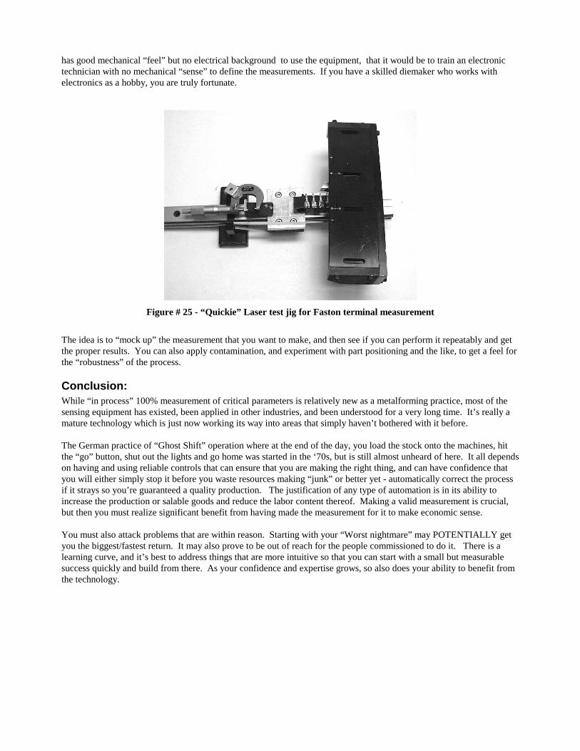
Figure # 25 - “Quickie” Laser test jig for Faston terminal measurement
The idea is to “mock up” the measurement that you want to make, and then see if you can perform it repeatably and get the proper results. You can also apply contamination, and experiment with part positioning and the like, to get a feel for the “robustness” of the process.
Conclusion: While “in process” 100% measurement of critical parameters is relatively new as a metalforming practice, most of the sensing equipment has existed, been applied in other industries, and been understood for a very long time. It’s really a mature technology which is just now working its way into areas that simply haven’t bothered with it before. The German practice of “Ghost Shift” operation where at the end of the day, you load the stock onto the machines, hit the “go” button, shut out the lights and go home was started in the ‘70s, but is still almost unheard of here. It all depends on having and using reliable controls that can ensure that you are making the right thing, and can have confidence that you will either simply stop it before you waste resources making “junk” or better yet - automatically correct the process if it strays so you’re guaranteed a quality production. The justification of any type of automation is in its ability to increase the production or salable goods and reduce the labor content thereof. Making a valid measurement is crucial, but then you must realize significant benefit from having made the measurement for it to make economic sense. You must also attack problems that are within reason. Starting with your “Worst nightmare” may POTENTIALLY get you the biggest/fastest return. It may also prove to be out of reach for the people commissioned to do it. There is a learning curve, and it’s best to address things that are more intuitive so that you can start with a small but measurable success quickly and build from there. As your confidence and expertise grows, so also does your ability to benefit from the technology.