Embed Size (px)
Citation preview

Nationei Bureau of Star.caids
Library, N. W. Bldg.
AUG 1 9 1952
S6
Methods and Equipment for Testing
Printed-Enamel Felt-Base Floor Covering
United States Department of Commerce
National Bureau of Standards
Building Materials and Structures Report 130

BUILDING MATERIALS AND STRUCTURES REPORTS
On request, the Superintendent of Documents, U. S. Government Printing Office, Wash-ington 25, D. C., will place your name on a special mailing list to receive notices of newreports in this series as soon as they are issued. There will be no charge for receivingsuch notices.
An alternative method is to deposit with the Superintendent of Documents the sum of $5,with the request that the reports be sent to you as soon as issued, and that the cost there-of be charged against your deposit. This will provide for the mailing of the publicationswithout delay. You will be notified when the amount of your deposit has become exhausted.
If 100 copies or more of any report are ordered at one time, a discount of 25 percent is
allowed. Send all orders and remittances to the Superintendent of Documents, U. S.Government Printing Office, Washington 25, D. C.
The following publications in this series are available by purchase from the
Superintendent of Documents at the prices indicated:
BMS2 Methods of Determining the Structural Properties of Low-Cost House Constructions.. 10ft
BMS3 Suitability of Fiber Insulating Lath as a Plaster Base 150BMS4 Accelerated Aging of Fiber Building Boards 100BMS5 Structural Properties of Six Masonry Wall Constructions 200BMS6 Survey of Roofing Materials in the Southeastern States 150BMS8 Methods of Investigation of Surface Treatment for Corrosion Protection of Steel 150BMS9 Structural Properties of the Insulated Steel Construction Co.'s "Frameless-Steel"
Constructions for Walls, Partitions, Floors, and Roofs 100BMS10 Structural Properties of One of the "Keystone Beam Steel Floor" Constructions
Sponsored by the H. H. Robertson Co 100BMS11 Structural Properties of the Curren Fabrihome Corporation's "Fabrihome" Con-
structions for Walls and Partitions 100BMS12 Structural Properties of "Steelox" Constructions for Walls, Partitions, Floors, and
Roofs Sponsored by Steel Buildings, Inc 150BMS14 Indentation and Recovery of Low-Cost Floor Coverings 100BMS15 Structural Properties of "Wheeling Long-Span Steel Floor" Construction Sponsored
by the Wheeling Corrugating Co 100BMS16 Structural Properties of a "Tilecrete" Floor Construction Sponsored by Tilecrete
Floors, Inc 100BMS17 Sound Insulation of Wall and Floor Constructions 200Supplement to BMS17, Sound Insulation of Wall and Floor Constructions 50Supplement No. 2 to BMS17, Sound Insulation of Wall and Floor Constructions 150BMS18 Structural Properties of "Pre-fab" Constructions for Walls, Partitions, and Floors
Sponsored by the Harnischfeger Corporation 100BMS20 Structural Properties of "Twachtman" Constructions for Walls and Floors Spon-
sored by Connecticut Pre-Cast Buildings Corporation 100BMS21 Structural Properties of a Concrete-Block Cavity-Wall Construction Sponsored by
the National Concrete Masonry Association 100BMS22 Structural Properties of "Dun-Ti-Stone" Wall Construction Sponsored by the W. E.
Dunn Manufacturing Co 100BMS23 Structural Properties of a Brick Cavity-Wall Construction Sponsored by the Brick
Manufacturers Association of New York, Inc 100BMS24 Structural Properties of a Reinforced-Brick Wall Construction and a Brick-Tile
Cavity-Wall Construction Sponsored by the Structural Clay Products Institute 150BMS25 Structural Properties of Conventional Wood-Frame Constructions for Walls, Parti-
tions, Floors, and Roofs 200BMS26 Structural Properties of "Nelson Pre-Cast Concrete Foundation" Wall Construction
Sponsored by the Nelson Cement Stone Co., Inc 100BMS27 Structural Properties of "Bender Steel Home" Wall Construction Sponsored by the
Bender Body Co 100BMS28 Backflow Prevention in Over-Rim Water Supplies 150BMS29 Survey of Roofing Materials in the Northeastern States 200BMS30 Structural Properties of a Wood-Frame Wall Construction Sponsored by the
Douglas Fir Plywood Association ,__ 150BMS32 Structural Properties of Two Brick-Concrete-Block Wall Constructions and a Con-
crete-Block Wall Construction Sponsored by the National Concrete MasonryAssociation 150
BMS33 Plastic Calking Materials . 150
[List continued on cover page in]
UNITED STATES DEPARTMENT OF COMMERCE . Charles Sawyer, Secretary
NATIONAL BUREAU OF STANDARDS • A. V. Astin, Aclinf, Director
Methods and Equipment for Testing
Printed-Enamel Felt-Base Floor Covering
George G. Richev, Elizabeth H. McKenna, and Robert B. Hobbs
Building Materials and Structures Report 130
Issued May 1, 1952
For sale by the Superintendent of Documents, U. S. Government Printing Office, Washington 25, D. C.
Price IS cents

Foreword
Printed-enamel felt-base floor coverings form the largest class of resilient
non-textile floor coverings, which include linoleum, rubber tile, asphalt tile,
and plastic tile and sheeting. The annual production of printed-enamel
floor coverings, known in the trade as "felt-base rugs", amounts to more than
200 million square yards, valued at over 80 million dollars at the factory.
Despite this large volume of production, no generally accepted methods for
the evaluation of the properties of this material have been established. This
paper describes methods and equipment for measuring the Aveight, over-all
thickness, thickness of enamel and of seal coat, resistance to scrubbing with
cleaning compound, resistance to kerosine, flexibility, and tearing strength.
The results of laboratory tests are correlated with results of service tests of
eleven proprietary products. The correlation was significant for all properties
studied except thickness of seal coat, but no single property was outstanding
in its level of significance. Thus it appears that these tests will be useful for
manufacturers, purchasers of large quantities, and others interested in evaluat-
ing printed-enamel felt-base floor coverings.
A. V. Astin, Acting Director.
ContentsPage
Foreword ii
1. Introduction 1
2. Materials tested . 1
3. Test methods and equipment 2
3.1. Atmospheric conditions 2
3.2. Weight . __i 2
3.3. Flexibility 1 2
3.4. Tear resistance 2
3.5. Thicknesses of the seal coat and of the enamel coat 3
3.6. Over-all thickness 3
3.7. Resistance to cleaning compound 3
3.8. Resistance to kerosine 4
4. Service tests 4
4.1. Test of materials laid in corridor 4
4.2. Test of materials laid on stairway 5
5. Results of tests 5
5.1. Correlation of results of laboratory and service tests 5
5.2. Measurements of weight and thickness 8
5.3. Flexibility..- . 8
5.4. Tearing strength 9
5.5. Resistance to cleaning compound 9
5.6. Resistance to kerosine :__ 9
5.7. Service tests 9

Methods and Equipment for Testing Printed-Enamel
Felt-Base Floor Covering
George G. Richey, Elizabeth H. McKenna, and Robert B. Hobbs
This paper describes methods and equipment for measuring the weight, over-all thickness,
thickness of enamel and of seal coat, resistance to scrubbing with cleaning compound, resist-
ance to kerosine, flexibility, and tearing strength of printed-enamel felt-base floor covering.
Results of laboratory tests are correlated with results of service tests of 11 proprietary
products. The correlation was significant for all properties studied except thickness of
seal, coat, but no single property was outstanding in its level of significance.
1. Introduction
Procedures for the evaluation of the properties
of some nontextile floor coverings, such as linoleum,
rubber tile, and asphalt tile, have been established
for many years. These methods and the equip-ment associated with them have been acceptedgenerally by consumers and manufacturers.Printed-enamel felt-base floor covering attains anannual volume of production amounting to 200million square yards, valued at 80 million dollars
at the factory, according to the 1947 Census of
Alanufactures. Although this volume of produc-tion exceeds that of any other type of nontextile
floor covering, no generally accepted methods of
tests have been established for the evaluation of
the properties of printed-enamel felt-base floor
coverings.
The purpose of this investigation was to developsuch methods of laboratory tests, and to correlate
the results of laboratory tests with the behavior of
the material in actual service, insofar as
practicable.
The methods reported here are suitable for theevaluation of the following properties: Weight,flexibility, tear resistance, thickness of enamel
coating, over-all thickness, resistance to cleaning
compounds, and resistance to kerosine. Thesemethods and the results given in this paper mayalso be employed in the development of improve-ments in this type of floor covering.
2. Materials Tested
Eleven samples of printed-enamel felt-base floor
covering purchased on the open market from re-
tail outlets in Washington, D. C, were included
in this investigation. They represented all avail-
able grades from all the manufacturers whoseproducts were obtainable at retail at the time.
The samples included materials from all price
ranges.
Each floor covering consisted of a prepared felt
backing to one side of which was applied an enamelcoating, which constituted the wearing surface.
The under side of the felt was painted. Micro-scopic examination of sections cut from the floor
coverings showed, on all except one, that a paint
coating had also been applied on the upper side of
the felt backing before application of the enamelcoat. Descriptions of the materials are given
in table 1.
Table 1. Manufacturer, size, and other identification of printed-enamel felt-base floor coverings tested
DesignationManu-facturer
Size Form Other identification bymanufacturer
Description of color and pattern
C-L.
C-2_.C-3_.C-4_.
C-5_.
C-6.
C-7_.C-8_.C-9_.
C-10
C-ll
WxY
Xz
ft.
9 x 12
12 x 1212 x 129 x 12
9x12
9 x 12
9x 12
69 x 12
9x12
9 x 12
Rug
..do._.do.__do.
-do_
.do.
.do-Roll.Rug.
.do.
.do-
Deluxe, heavy weight.
Standard, second-Standard, regular-Deluxe
_do-
_ do-
None—
.
do_do.
First grade-
None
Leaf pattern in various shades of red with slight amounts of green,
yellow, and black.Gray, black, blue, and red tile pattern on ivory background.Light tan, black, blue, and red tile pattern on ivory background.Tan and brown dot pattern with some red and black and scattered
blocks of green, yellow, black, and red on cream background.Tile pattern in various shades of gray with contrasting gray dots; afew solid blocks of yellow, blue, red, and green on ivory back-ground.
Floral pattern in blue, green, brown, tan, and orange on back-ground of two shades of red.
Tile pattern in gray, black, ivory, red, and tan.
Block pattern in gray, red, and black on ivory background.Floral pattern in various shades of red with green, yellow, brown,and red on a background predominately tan and gray.
Leaf pattern in tan and brown shades, with slight amounts of red,
orange, ivory, and green on chocolate background.Floral pattern in black, white, and tan with slight amount of greenon red background.
985468—52 1

3. Test Methods and Equipment
3.1. Atmospheric Conditions
Measurements of all properties were made withspecimens conditioned in an atmosphere of 65 ±2percent relative humidity at a temperature of 70°
±2° F for at least 48 hr. The specimens werealso tested under these atmospheric conditions.
These conditions were adopted simply becausethey were the ones most conveniently available at
the time the tests were made. There seems to beno reason to prefer them over the present standardconditions of 73° F and 50-percent relative
humidity.
3.2. Weight
The weight of each floor covering was obtainedby weighing and measuring specimens approxi-mately 4 by 4 in. in size cut from the full thickness
of the material. Weighings were made to the
nearest gram, and lineal dimensions were measuredto the nearest 0.02 in. From the weight and meas-urements so obtained, using three specimens, the
average weight per square yard was calculated.
3.3. Flexibility
Specimens, each 2 by 8 in., were cut longitudi-
nally and transversely from each of the floor cov-erings, then bent over a series of mandrels of
decreasing size, ranging in diameter from 4 to 1 in.,
by increments of }i in. , until cracking of the enamelcoating was observed. Each strip was bent at its
center over the mandrel, with the felt backing onthe inside, through an arc of 180° in approximately5 sec. and at approximately a uniform speed. Twospecimens were tested from each of the floor
coverings.
3.4. Tear Resistance
In the study of tear resistance, the Elmendorftear tester modified to double its capacity, as
described by Carson and Snyder, 1 was used. Themethod of operation of the tester was similar to
that described in the ASTM test for tearing resist-
ance of paper, 2 except for the number, size, andshape of specimens used. This method deter-
1 F. T. Carson and L. W. Snyder, Paper Trade J. 86, 13 (1928).2 ASTM Designation D689-44, ASTM Standards,.Part III-B (1946).
Figure 1. Dimensions of specimen for test of tear resistance.
mines the average force, in grams, required to tear
a single rectangular specimen by measuring thework done in tearing the specimen through a fixed
distance. The scale of the tester is graduated to
indicate the ratio of the work done (in gram-centimeters) in tearing the specimen to the total
tearing length of 16 sheets. This total tearinglength is 16 times 4.3 cm times 2, that is, 137.6 cm.The factor 2 is included because, in order to tear
a sheet through a given distance, the tearing force,
must be exerted through twice that distance.
Preliminary tests were made to compare, withthe rectangular specimen, one having a semicircu-
lar shape, with a radius of 38 mm, above the topof the initial slit. The dimensions of the specimenare shown in figure 1
.
For the rectangular specimen, the length of tear
was 43 mm. As the capacity of the instrumentwas doubled, the indicated scale readings weremultiplied by the factor 16X2 to obtain the
average tearing force in grams.For the specimen with the semicircular area, the
radius of curvature, 38 mm, was equal to the lengthof tear. Hence, the indicated scale readings weremultiplied by the factor (16X2X4.3)/3.8, that is,
36.2, to obtain the average tearing force for the
specimen.The residts of comparative tests on the two
shapes of specimens for two varieties of floor cover-
ing are given in table 2. Each mean represents
eight determinations. The variability for the
rectangular specimens is much greater than for
those with the semicircular area. For this reason,
further tests on all the floor coverings were madewith the semicircular specimens.
Table 2. Tearing strength, in grams, of rectangular and semicircular specimens
Sample
Rectangular specimen Semicircular specimen
Machine directionCross-machine
directionMachine direction
Cross-machinedirection
Mean Std. dev. Mean Std. dev. Mean Std. dev. Mean Std. dev.
C-5C-6._
954965
6446
1,2741,356
130144
915898
4022
1,1701,025
79
83
2

In making subsequent tests, five specimenswere cut from each of the two principal directions
of the floor covering and tested. The indicated
scale reading was multiplied by the factor 36.2 to
obtain the tearing force in grams. This value
was rounded off to the nearest 10, and in the
mean of the five determinations for each direction
was recorded.
3.5. Thicknesses of the Seal Coat and of theEnamel Coat
Thicknesses of the seal coat and the enamelcoat were determined by observation with a meas-uring microscope on sections cut at a right angle
to the surface of the floor covering. The equip-
ment used was capable of making measurementsaccurate to 0.0005 in. The arithmetic mean of
10 measurements was taken as the thickness of
the seal coat. The arithmetic mean of 10 meas-urements of sections comprising at least three
different colors of the pattern was taken as the
thickness of the enamel.
3.6. Over-all Thickness
The over-all thickness of the floor coveringunder a load of 3.0 ±0.1 oz exerted by a weightthrough a flat contact foot 0.25 ±0.01 in. in diam-eter was determined by means of a dial microm-eter. Measurements were made to the nearest
0.001 in. The arithmetic mean of five measure-ments was taken as the over-all thickness of thematerial.
3.7. Resistance to Cleaning Compound
The resistance of the enamel coating to scrubbingwith an alkaline soap solution was determinedwith a modified Schiefer abrasion machine. 3 Thisapparatus was modified to use a nylon bristle
brush as the abradant, and to accommodate a brass
cup to retain the test specimen and the solution.
Figure 2 shows the brush, cup, and specimen in
position on the machine.The brush, shown schematically in figure 3,
was made from a commercial article by sawing it in
half transversely and cutting the slots by which thebrush is engaged in the holder. Each tuft consists
of 34 nylon bristles, each 0.014 in. in diameter, andthe backing is of polymethyl methacrylate. Thebristles were worn to a uniform length before useby rotating the brush 1,000 times in the Schiefer
machine against B-A flint paper 1/0, with a loadof 4.14 lb. In order to keep the solution distrib-
uted over the surface of the specimen during op-eration of the machine, a distributor plate of
acrylic plastic, % in. wide, was fixed along aradius of the cup, so as to just clear the surface of
the specimen and the side of the cup. The total
load on the brush was 4.14 lb.
The solution used for the test contained 0.5
percent of soap, conforming to the Federal Speci-
fication for chip soap, 4 and 0.5 percent of chem-ically pure sodium carbonate. It had a pH of
about 10.6.
In order to simulate more closely the conditions
of scrubbing in actual service, the temperature of
the solution was maintained at 45° ±2° C during
the test. This was accomplished by keeping the
entire apparatus in a heated enclosure, with the
temperature of the solution being measured by a
thermocouple immersed in it.
The test specimen was cut with a circular steel
die having a diameter of 4 X% 2 in. It was placed
in position and the cup was attached. Approxi-mately 50 ml of the solution, previously warmedto 50° C, was placed in the cup. The machinewas then operated for 9,000 revolutions of the
specimen against the brush. The specimen wasremoved, rinsed with tap water, allowed to dry at
room temperature, and the area of seal coat or
felt exposed was measured to the nearest 0.01 in.2
with a planimeter. The areas in square inches
exposed on five test specimens from each material
4 Federal Specification P-S-566a for Soap; Chips.
Figure 2. Schiefer abrasion machine with cup and brush
for measuring resistance to cleaning compound.
I » I ' t I l » c
'it
Mil
1II
II
3"
8
3 Herbert F. Schiefer, Lawrence E. Crean, and John F. Krasny. J. Re-search NBS 42, 481 (1949) RP1988. Figure 3. Brush used with Schiefer abrasion machine.
3

were added, and the result taken as the effect of
scrubbing with the cleaning compound.In order to study the effect of variations be-
tween the brushes on the results of this test, acomparison was made of one brush that had beenused for tests of 70 specimens (600,000 rotationsin the Schiefer abrasion machine, representingapproximately 40 hr of service in the machine)and three new brushes. Twelve strips were cutat random from sample C-5, and four test speci-
mens were cut from each strip. A specimen fromeach strip was tested with each brush. The test
procedure was identical with that described pre-
viously. A statistical analysis of the results
showed there were no significant differences in
the results obtained with the used brush in com-parison with the new brushes, and there were nosignificant differences in the effects produced bythe three new brushes in comparison with eachother. The tabulation of this analysis is givenin table 3.
Table 3. Analysis of variance of effect of cleaning com-pound on sample C—5, using an old brush and three newbrushes
Source of variationDegrees
of
freedom
Sum of
squaresMean square
Between means of strips
Between means of brushesInteraction
11
3
33
2. 14600. 19602. 5774
0. 1951.0653.0781
Total 47 4. 9194 0. 1047
In a few instances it was necessary to add about10 ml of solution during the test because of losses
from evaporation, leakage, and absorption of solu-
tion by the specimen. Test specimens from twoof the floor coverings were run for less than theprescribed 9,000 rotations because the enamelcoating was removed relatively rapidly from bothof these materials.
3.8. Resistance to Kerosine
A metal ring of approximately 4 in. inside dia-meter was cemented to the enameled surface of
floor covering by means of cellulose nitrate
adhesive. The adhesive was applied on the outersurface of the ring and the floor covering. Carewas taken to prevent any of this adhesive fromgetting on the test area enclosed by the ring.
After a 24-hr drying period (minimum), 25 mlof kerosine was placed on the test area, and this
expose was allowed to continue for 72 hr. At theend of this period the kerosine was removed, thetest area was rinsed with tap water, and anyblistering of the enamel noted.
4.1.
4. Service Tests
Test of Materials Laid in Corridor
The corridor connecting the second floors of theMunitions Building and the Navy DepartmentBuilding in Washington, D. C. was selected for
this installation. This corridor is about 100 ft
long and 7% ft wide, with no doors except thoseat each end. The existing tongued-and-groovedwood floor in the corridor was repaired and the
entire area was sanded to remove high spots.
Each specimen installed was approximately 60in. long and 84 in. wide, placed so that its greater
dimension extended across the width of the cor-
ridor. The specimens were separated from eachother by means of 1-in. strips of floor covering,
nailed to the wood floor. A clearance of % in.
was allowed between the edge of the specimen andthe adjacent edge of the strip. These strips
served as furring under strips of galvanized sheet
metal 3 in. in width, which were used to cover the
edges of adjacent specimens. The sheet-metalstrips were nailed to the wood floor through the
furring strips. By this method of installation
linear dimensional changes of the floor coverings
could occur without causing buckling of the speci-
mens.The test installation was opened to traffic in
February 1947. The specimens were moppedtwice each week with water to which 2 percent
(by weight) of cleaning compound was added.The analysis of the cleaning compound used is
given in table 4.
Table 4. Analyses of cleaning compounds used in service
tests
Property
Matter volatile at 105° CNeutral inorganic salts
Sodium chloride (NaCl)Free alkali (NaOH)Rosin, sugar, etcAnhydrous soapSynthetic detergentInsoluble siliceous material
.
Alkaline salts (Na2COs)
Total.
MunitionsBuilding
installation
3%59%1%None
doNone detected.37%
100%.
NationalBureau ofStandardsinstallation
10%
NoneDo.
14
56%20%
100%
After approximately 12 months of service, 14
observers rated the specimens in comparison witheach other, on the basis of distinctness of pattern,
gloss, resistance to soiling, and general appearance.
These observers included scientific personnel of
the National Bureau of Standards, representatives
of manufacturers of printed-enamel felt-base floor
covering, and consumers. A relative rating of
A, B, C, or D, was assigned to each specimen byeach observer. An 'A" rating indicated the best
floor coverings, and "B", "C", or "D" ratings
progressively poorer materials. These ratings
were then tabulated.Numerical values of service ratings were ob-
tained on the basis that each observer had anequal number of total points to assign (a total of
50 points was arbitrarily selected). In addition,
ratings of A, B, C, and D were credited in the
proportion of 4:3:2:1, respectively, for every
observer. By this method the over-all influence
4

of each observer's rating was equal, regardless ofwhether the particular observer tended to ratehigh or low.
Traffic counts taken in the corridor on variousdays indicated approximately 16,000 people tra-
versed the corridor per week.
4.2. Test of Materials Laid on Stairway
Specimens of the floor covering, each 10 by 36in., were installed on a stairway at the NationalBureau of Standards. All specimens werecemented directly to the existing marble treadswith a commercial linoleum paste adhesive. (Twospecimens came loose during the test period.
These were relaid with a rubber-resin adhesive.)
The specimens were mopped twice each week withwater containing 1 percent of (by weight) cleaningcompound. The analysis of the cleaning com-pound used is given in table 4.
The test installation was in service from March1947 to February 1948. At the end of this period,
the test specimens were taken up and washed withwater to which 1 percent of the cleaning compoundwas added. They were rated with respect to
appearance in comparison with each other as A,B, C, or D. An "A" rating indicated the bestfloor coverings and "B", "C", or "D" progres-sively poorer materials. Photographs of some of
the specimens, when rated, are shown in figure 4.
5.1.
5. Results of Tests
Correlation of Results of Laboratoryandf Service Tests
The results of laboratory and service tests aregiven in tables 5, 6, and 7. The results of theservice tests are of primary importance as corre-
lation with these results is used as an index of theusefulness of any laboratory test in evaluatingdurability. The test in the Munitions Buildingis thought to be the better criterion of the dura-bility of the specimens, both because use as a floor
covering more nearly simulates actual use in thehome than does use as a stair covering, and becausethe evaluations of the worn materials represented
the opinions of a larger number of observers withmore varied personal background. An analysis of
variance of the service ratings, summarized in
table 7, shows that there are highly significant
differences between specimens, but not betweenobservers. The results of the service test on thestairway can be taken as confirming the results
of the Munitions Building test. The same twospecimens, C-4 and C-6, are ranked as best, andthe same two, C-7 and C-ll, as "worst." Resultsfor the other specimens in the stairway test wereinconclusive.
In comparing the results of the floor service test
with the results of laboratory tests, correlations
were based on rank as the evaluations by thedifferent observers rated the specimens in order of
Table 6. Results of service tests of printed-enamel felt-base
floor covering
Designation
Rating
NationalBureau of
Standardsinstallation
MunitionsBuilding
installation
C-l CBBABADCCCD
45.045.047.658.056.567.021.637.154.254.317.142.750. 2
56.7
C-2 _._
C-3C-4C-5 _
C-6. __
C-7C-8C-9...C-10C-llC-2AC-3A BC-10A __
Table 7. Analysis of variance of adjusted service ratings for11 printed-enamel felt-base floor coverings by 14 observers
Source of variationDegrees of
freedomSum of
squaresMeansquare
Between means of floor cover-ings.. 10
13
130
167. 721.37
70. 97
16.770.11.55
Between means of observersInteraction.. _. .
Total 153 240. 06 1. 57
Table 5. Physical properties and performance tests of floor coverings
Sample Averageweight
Flexi-bility
Tearing strength Thickness—average
Effect ofcleaningcompound
Effect ofkerosineMachine
direction
Cross-machinedirection
Seal coatEnamelcoat
Over-all
tb/ydi m. a9 0 Mils Mils Mils in.1
C-l 3.1 3 900 1,060 0.0 5.0 65 5.44 NoneC-2 3.0 3H 890 1,270 7.0 5.5 55 0. 06 Do.C-3.. 2.8 <1 900 1,320 5.0 5.0 51 .02 Do.C^t 3.3 2 1, 110 1,280 6.0 5.5 66 .01 Do.C-5 3.2 <1 920 1,170 5.0 6.5 61 1.41 Do.C-6 3.2 2 900- 1,020 3.5 6.0 72 0. 00 Do.C-7 2.0 3H 590 590 4.0 2.0 47 » 57.2 BlisteredC-8____ 2.7 4 830 1,130 6.0 5.0 51 0. 67 NoneC-9__ 3.6 1 920 940 4.5 4.0 71 .20 Do.C-10 2.5 3H 570 750 6.0 4. 5 53 .06 Do.C-ll 2.3 <1 630 700 4.0 0.5 49 " 57.2 Blistered
o Diameter of mandrel on which cracking was first observed. b 6,500 rotations instead of 9,000. ° 4,000 rotations instead of 9,000.

Figure 4. Specimens of floor covering after service test on stairway.
C-7 and C-ll show greatest deterioration, C-6 the least; others are intermediate.
6

Figure 4. Specimens of floor covering after service test on stairway.—(Continued)
C-7 and C-ll show greatest deterioration, C-6 the least; others are intermediate.

Figure 5. Rank correlation of service and laboratory test
results.
durability rather than giving quantitative results,
and the final ratings, given in table 6, represent anintegration of these rankings. Diagrams in whichthe ranks for each sample in six laboratory tests
are plotted against the ranks in the floor service
test are shown in figure 5.
From these diagrams it is apparent that there
is practically no correlation between seal-coat
thickness and durability in service, but that there
is some correlation between each of the other prop-erties and the behavior of the material in service.
These conclusions were checked by calculating
measures of correlation from ranks, using theformula
6L> 2
p N(N2-1)'
wherep= the measure of correlation from ranks for
a given propertyD=the difference between the rank in the
laboratory test for a given propertyand the rank in the service test for eachfloor covering
N=the number of materials in the test, thatis 11.
The values of p so obtained were as follows for
the various properties measured:
Weight per unit area 0. 73Tearing strength (machine direction) . . 62Thickness of enamel coat . 69Thickness of seal coat .08Over-all thickness . 80Resistance to cleaning compound .75
Each of these values of p, except that for thicknessof seal coat, shows a significant positive correlation.
5.2. Measurements of Weight and Thickness
As measurements of weight and over-all thick-ness are the easiest and quickest to make of all
the tests described in this paper, it is interestingthat they show rather high degrees of correlationwith the results of service tests. As the twosamples giving by far the poorest wear in theservice tests had weights of 2.0 and 2.3 lb/yd2
, it
it would seem that a weight of at least 2.5 lb/yd2is
the minimum that would be expected for amaterial giving good service. Similar considera-tions lead to a minimum value of 0.050 in. forover-all thickness.
The durability of the enamel coat is highlyimportant as the decorative effect of the floor
covering depends entirely on this layer. When it
has become so badly worn as to impair thedecorative effect, the consumer usually wishes toreplace it. The significant correlation between thethickness of enamel coat and the service ratingreflects this circumstance. From the results it
would appear that the enamel coat must be atleast 4 mils thick to give satisfactory service.
The purpose of the seal coat is to prevent "bleed-ing" of the saturant in the felt base into theenamel coating. It appears that when the mini-mum thickness necessary to perform this functionis applied, any greater thickness of seal coat addsnothing to the serviceability of the floor covering.As one sample had no seal coat, yet showed noadverse effect from this omission, there is noconclusive evidence from this experiment that aseal coat must be required.
5.3. Flexibility
Printed-enamel felt-base floor covering is fur-
nished to retail outlets in roll form. Hence it is
necessary that the enamel coating be sufficiently
flexible to withstand unrolling of the floor coveringwithout cracking of the coating. Yard goods,in addition, are often purchased for use as wall-to-
wall floor covering, and bending of the material will
usually be necessary during fitting at the time of
installation. On the basis of requirements in
existing Federal specifications, 4 felt-base floor
covering that can be bent without cracking overa mandrel 4 in. in diameter or smaller is desirable.
Of the floor coverings included in this investiga-
tion only sample C-8 failed to have this degree of
flexibility. After a 3-week period of installation,
the specimen of this floor covering in the service
installation at the Munitions Building exhibited
marked cracking of the enamel coating. All the
other specimens in the service installation at this
same time showed either no cracking or slight
cracking of the coating. It was to be expectedthat the enamel coatings would harden and lose
flexibility with age. This tendency was evident
in the test at the Munitions Building, for after
approximately 1 year of service, all specimens,
4 Federal Specification LLL-F-471 for Floor Coverings; Felt-Backed.
8
except that from sample C-l, exhibited cracking
on some areas of the surface.
5.4. Tearing Strength
The tearing strength is a property of impor-tance in connection with the unrolling and laying
of a floor covering, as well as its resistance to tears
caused by stubbing the toe of one's shoe or a
similar hard object against the edge of the cover-
ing. This property also shows a significant cor-
relation with serviceability. Two of the three
samples having tearing strengths of less than 700 gwere the two showing the poorest durability.
The majority of manufacturers apparently haveno difficulty in making a product with a tearing
strength of 800 g or more.
5.5. Resistance to Gleaning Compound
The statement is sometimes heard in the floor-
covering trade that "more floor coverings are
worn out by scrubbing than by being walked on."
It seems to be a substantiation of this view that
the results of the test for resistance to scrubbingwith cleaning compound showed a significant
correlation with serviceability. It should benoted that the two floor coverings that recieved
the lowest service ratings were also the poorest in
resistance to cleaning compound, and the twofloor coverings that recieved the highest service
rating were also the best in resistance to cleaning
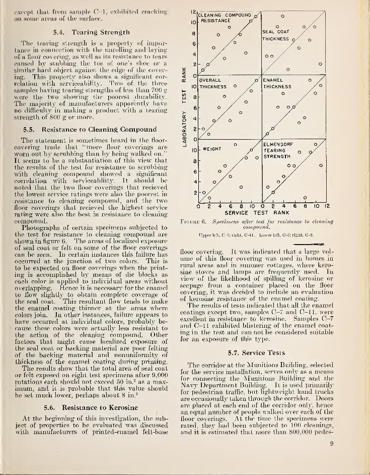
compound.Photographs of certain specimens subjected to
the test for resistance to cleaning compound are
shown in figure 6. The areas of localized exposureof seal coat or felt on some of the floor coverings
can be seen. In certain instances this failure hasoccurred at the junction of two colors. This is
to be expected on floor coverings when the print-
ing is accomplished by means of die blocks as
each color is applied to individual areas withoutoverlapping. Hence it is necessary for the enamelto flow slightly to obtain complete coverage of
the seal coat. This resultant flow tends to makethe enamel coating thinner at the areas wherecolors join. In other instances, failure appears to
have occurred at individual colors, probably be-
cause these colors were actually less resistant to
the action of the cleaning compound. Otherfactors that might cause localized exposure of
the seal coat or backing material are poor felting
of the backing material and nonuniformity of
thickness of the enamel coating during printing.
The results show that the total area of seal coator felt exposed on eight test specimens after 9,000rotations each should not exceed 50 in.
2 as a max-imum, and it is probable that this value shouldbe set much lower, perhaps about 8 in. 2
5.6. Resistance to Kerosine
At the beginning of this investigation, the sub-ject of properties to be evaluated was discussedwith manufacturers of printed-enamel felt-base
z<
o<rrOCD<_J
02468 10 02468 10 12
SERVICE TEST RANK
Figure 6. Specimens after test for resistance to cleaningcompound.
Upper left, C-l; right, O-ll. Lower left, O-S; right, C-8.
floor covering. It was indicated that a large vol-
ume of this floor covering was used in homes in
rural areas and in summer cottages, where kero-
sine stoves and lamps are frequently used. Inview of the likelihood of spilling of kerosine or
seepage from a container placed on the floor
covering, it was decided to include an evaluation
of kerosine resistance of the enamel coating.
The results of tests indicated that all the enamelcoatings except two, samples C-7 and C-ll, wereexcellent in resistance to kerosine. Samples C-7and C-ll exhibited blistering of the enamel coat-
ing in the test and can not be considered suitable
for an exposure of this type.
5.7. Service Tests
The corridor at the Munitions Building, selected
for the service installation, serves only as a meansfor connecting the Munitions Building and the
Navy Department Building. It is used primarilyfor pedestrian traffic, but lightweight hand trucks
are occasionally taken through the corridor. Doorsare placed at each end of the corridor only, hencean equal number of people walked over each of the
floor coverings. At the time the specimens wererated, they had been subjected to 100 cleanings,
and it is estimated that more than 800,000 pedes-
9

trians had traversed the corridor. Only specimensC—7 and C-ll had shown a marked loss in decora-
tive effect at the time the ratings were assigned.
The service ratings of replicate specimens of floor
coverings C-2, C-3, and C-10 agree very well;
the maximum difference between any two wasfound to be 3 units.
An analysis of variance of the ratings of speci-
mens C-l through C-ll (the replicates were notincluded) was made. This analysis showed that
practically all the variability in the ratings couldbe attributed to the floor coverings, and that verylittle could be attributed to the observers andother causes.
The specimens installed on the East stairway,
Industrial Building, National Bureau of Standards,were subjected to much more severe conditions
than those in the corridor at the MunitionsBuilding. The relatively rapid rate of wear of
flooring materials on stair treads is well recognized,but in this instance the cleaning compound also
contained a large percentage of siliceous, material,which probably further accelerated deterioration.
Although the exposure conditions were widely dif-
ferent in the two service tests, the relative orderof results was essentially the same in both tests.
The authors express their appreciation to HelenG. Wheeler for assistance in the preparation ofspecimens and making numerous determinationsof the properties of the floor coverings. Theassistance of John Mandel in the design of experi-
ments and analysis of the data is also gratefully
acknowledged.
Washington, August 24, 1951.
10

BUILDING MATEKIALS AND STRUCTURES REPORTS
[Continued from cover page n]
BMS34 Performance Test of Floor Coverings for Use in Low-Cost Housing: Part 1 150BMS36 Structural Properties of Wood-Frame Wall, Partition, Floor, and Roof Construc-
tions With "Red Stripe" Lath Sponsored by The Weston Paper and Manufac-turing Co 100
BMS38 Structural Properties of Two "Dunstone" Wall Constructions Sponsored by theW. E. Dunn Manufacturing Co 100
BMS39 Structural Properties of a Wall Construction of "Pfeifer Units" Sponsored by theWisconsin Units Co 100
BMS42 Structural Properties of Wood-Frame Wall and Partition Constructions with "Celo-tex" Insulating Boards Sponsored by The Celotex Corporation 150
BMS43 Performance Test of Floor Coverings for Use in Low-Cost Housing: Part 2 150BMS44 Surface Treatment of Steel Prior to Painting 100BMS47 Structural Properties of Prefabricated Wood-Frame Constructions for Walls, Partitions,
and Floors Sponsored by American Houses, Inc 200BMS48 Structural Properties of "Precision-Built" Frame Wall and Partition Constructions
Sponsored by the Homasote Co 150BMS49 Metallic Roofing for Low-Cost House Construction 200BMS50 Stability of Fiber Building Boards as Determined by Accelerated Aging 100BMS51 Structural Properties of "Tilecrete Type A" Floor Construction Sponsored by the Tile-
crete Co 100BMS52 Effect of Ceiling Insulation Upon Summer Comfort 150BMS53 Structural Properties of a Masonry Wall Construction of "Munlock Dry Wall Brick"
Sponsored by the Munlock Engineering Co 100BMS54 Effect of Soot on the Rating of an Oil-Fired Heating Boiler 100BMS55 Effects of Wetting and Drying on the Permeability of Masonry Walls 100BMS58 Strength of Soft-Soldered Joints in Copper Tubing 100BMS59 Properties of Adhesives for Floor Coverings 150BMS60 Strength, Absorption, and Resistance to Laboratory Freezing and Thawing of Building
Bricks Produced in the United States 300BMS61 Structural Properties of Two Nonreinforced Monolithic Concrete Wall Constructions _ 100BMS62 Structural Properties of a Precast Joist Concrete Floor Construction Sponsored by the
Portland Cement Association 150BMS63 Moisture Condensation in Building Walls 150BMS64 Solar Heating of Various Surfaces 100BMS65 Methods of Estimating Loads in Plumbing Systems 150BMS66 Plumbing Manual 350BMS67 Structural Properties of "Mu-Steel" Prefabricated Sheet-Steel Constructions for Walls,
Partitions, Floor, and Roofs, Sponsored by Herman A. Mugler 150BMS68 Performance Test for Floor Coverings for Use in Low-Cost Housing: Part 3 200BMS69 Stability of Fiber Sheathing Boards as Determined by Accelerated Aging 100BMS70 Asphalt-Prepared Roll Roofings and Shingles 200BMS71 Fire Tests of Wood- and Metal-Framed Partitions 200BMS72 Structural Properties of "Precision-Built, Jr." Prefabricated Wood-Frame Wall Con-
struction Sponsored by the Homasote Co 100BMS73 Indentation Characteristics of Floor Coverings 100BMS74 Structural and Heat-Transfer Properties of "U. S. S. Panelbilt" Prefabricated Sheet-
Steel Constructions for Walls, Partitions, and Roofs Sponsored by the TennesseeCoal, Iron & Railroad Co 200
BMS75 Survey of Roofing Materials in the North Central States 150BMS76 Effect of Outdoor Exposure on the Water Permeability of Masonry Walls 150BMS77 Properties and Performance of Fiber Tile Boards 100BMS78 Structural Heat-Transfer, and Water-Permeability Properties of Five Earth-Wall
Constructions 250BMS79 Water-Distributing Systems for Buildings 200BMS80 Performance Test of Floor Coverings for Use in Low-Cost Housing: Part 4 150BMS81 Field Inspectors' Check List for Building Constructions (cloth cover, 5 x 7% inches) 300BMS82 Water Permeability of Walls Built of Masonry Units 250BMS83 Strength of Sleeve Joints in Copper Tubing Made With Various Lead-Base Solders 150BMS84 Survey of Roofing Materials in the South Central States 150BMS85 Dimensional Changes of Floor Coverings With Changes in Relative Humidity and
Temperature 100BMS86 Structural, Heat-Transfer, and Water-Permeability Properties of "Speedbrik" Wall
Construction Sponsored by the General Shale Products Corporation 150BMS87 A Method for Developing Specifications for Building Construction—Report of Sub-
committee on Specifications of the Central Housing Committee on Research,Design and Construction 200
BMS89 Structural Properties of "Precision-Built, Jr." (Second Construction) PrefabricatedWood-Frame Wall Construction Sponsored by the Homasote Co 150
BMS90 Structural Properties of "PHC" Prefabricated Wood-Frame Construction for Walls,Floors, and Roofs Sponsored by the PHC Housing Corporation 150
[List continued on cover page iv]

BUILDING MATERIALS AND STRUCTURES REPORTS[Continued from cover page ra]
BMS92 Fire-Resistance Classifications of Building Constructions .. 300BMS93 Accumulation of Moisture in Walls of Frame Construction During Winter Exposure— 100BMS94 Water Permeability and Weathering Resistance of Stucco-Faced, Gunite-Faced, and
"Knap Concrete-Unit" Walls. 150BMS95 Tests of Cement-Water Paints and Other Waterproofings for Unit-Masonry Walls 250BMS96 Properties of a Porous Concrete of Cement and Uniform-Sized Gravel 100BMS97 Experimental Dry-Wall Construction With Fiber Insulating Board 100BMS98 Physical Properties of Terrazzo Aggregates 150BMS99 Structural and Heat-Transfer Properties of "Multiple Box-Girder Plywood Panels"
for Walls, Floors, and Roofs 150BMS100 Relative Slipperiness of Floor and Deck Surfaces 100BMS101 Strength and Resistance to Corrosion of Ties for Cavity Walls 100BMS 102 Painting Steel 100BMS103 Measurements of Heat Losses From Slab Floors 150BMS104 Structural Properties of Prefabricated Plywood Lightweight Constructions for Walls,
Partitions, Floors, and Roofs Sponsored by the Douglas Fir Plywood Association. _ 300BMS105 Paint Manual with particular reference to Federal Specifications $1. 25BMS106 Laboratory Observations of Condensation in Wall Specimens 100BMS108 Temperature Distribution in a Test Bungalow With Various Heating Devices 100BMS109 Strtengh of Houses: Application of Engineering Principles to Structural Design $1. 50BMS110 Paints for Exterior Masonry Walls 150BMS111 Performance of a Coal-Fired Boiler Converted to Oil 150BMSI 12 Properties of Some Lightweight-Aggregate Concretes With and Without an Air-
entraining Admixture 100BMS113 Fire Resistance of Structural Clay Tile Partitions 150BMS114 Temperature in a Test Bungalow With Some Radiant and Jacketed Space Heaters 250BMS115 A Study of a Baseboard Convector Heating System in a Test Bungalow 150BMS116 Preparation and Revision of Building Codes 150BMS117 Fire Resistance of Walls of Lightweight-Aggregate Concrete Masonry Units 200BMS118 The Stack Venting of Plumbing Fixtures 150BMS119 Wet Venting of Plumbing Fixtures.. 200BMS120 Fire Resistance of Walls of Gravel-Aggregate Concrete Masonry Units 150BMS121 Investigation of Failures of White-Coat Plasters 250BMS122 Physical Properties of Some Samples of Asbestos-Cement Siding 150BMS123 Fire Tests of Wood-Framed Walls and Partitions With Asbestos-Cement Facings 150BMS124 Fire Tests of Steel Columns Protected With Siliceous Aggregate Concrete 150BMS125 Stone Exposure Test Wall 300BMS126 The Self-Siphonage of Fixture Traps 200BMS127 Effect of Aging on the Soundness of Regularly Hydrated Dolomitic Lime Putties 150BMS128 Atmospheric Exposure Tests of Nailed Sheet Metal Building Materials 200BMS129 Fire Endurance of Shutters for Moving-Stairway Openings 100BMS130 Methods and Equipment for Testing Printed-Enamel Felt-Base Floor Covering 150