Embed Size (px)
Citation preview
Revista Romana de Interactiune Om-Calculator 9(3) 2016, 183- 216 © MatrixRom
Methods for Modelling Sketches in the Collaborative Prototyping of User Interfaces
Jorge Luis Pérez Medina Université catholique de Louvain, Louvain School of Management Research Institute Place des Doyens, 1 – B-1348 Louvain-la-Neuve (Belgium) E-mail:[email protected]
Abstract. Cross-functional teams with different technical backgrounds working on cross-platform environments require the production of flexible modeling of user interfaces in early steps of a design process. We observe that model-driven engineering (MDE) is currently gaining acceptance in many domains. However, existing solutions have no support for collaborative prototyping of user interfaces by sketching recognition for multiple stakeholders (e.g., designers, developers, final end users) working with heterogeneous computing platforms (e.g., smartphones, tablets, laptops, desktop), on different, perhaps separate or shared, interaction surfaces (e.g., tables, whiteboards) in a co-located way or remotely. This requires flexibility to explore and reuse vague and uncertain ideas as model sketching. This paper presents UsiSketch, an MDE method for modeling sketches that offers the following novel features resulting from a requirement elicitation process: sketching recognition on different surfaces based on a new recognition algorithm that accommodates very large surfaces and model-based design of user interfaces with collaboration.
Keywords: Sketching, Collaborative Prototyping, Graphical User Interface, Design Tools and Techniques.
1. Introduction Over the last years, Model-Driven Engineering (MDE) solutions and modeling platforms have been developed to simplify and automate many steps of MDE processes (Eisenstein et al., 2001). Kent (2003) argue that MDE promotes the reuse of productive modeling artifacts produced and consumed in the development process. We observe that MDE is currently gaining acceptance in many domains. However, several modeling platforms have focused on the last stages of the design process. The HCI domain shows a clear need for MDE methodology and tools to support User Interfaces Design (UID) (Pérez-Medina et al., 2007). Considering the UI as
184 Jorge Luis Pérez Medina
a model, MDE is able to answer the specific needs of the HCI community in terms of domain-specific meta-models and models. Nevertheless, the HCI community has to incorporate the proposed current standards used in MDE.
In the HCI domain, Buxton (2007) describes that the design process begins with ideation. Cross-functional teams with different technical backgrounds working on cross-platform environments require the production of several propositions of user interfaces at the latest stages of the design process. Those propositions are usually explored through sketches and prototypes considered as models (Demeure et al., 2011) which could then be submitted to static analysis for further exploration (Beirekdar et at 2002). Sketching is also particularly challenging when prototyping multi-platform user interfaces for multiple contexts of use (Florins et al., 2006). Coutaz (2010) found that MDE lacks support for early stages of design where the creativity and collaborative production of modeling sketches are crucial to elicit vague and uncertain ideas in projects requiring the design of advanced UIs.
In literature review, we found many software development frameworks like Gonzalez-Pérez (2010), interactive applications and academic research supporting sketching activities. However, the solutions have no support for distributed collaboration in very large surfaces, multi-level of prototyping and the execution of the user interface produced.
We present UsiSketch, a software-hardware environment to facilitate the tabletop collaborative prototyping of model-based UIs in early steps of the design process when multiple stakeholders have only a vague goal in mind of what should be produced. We present a method that recognizes UI sketches on very large interaction surfaces. UsiSketch is an Eclipse1 application that supports multiple computing platforms and provide support for collaboration of stakeholders and final users. Our solution addresses the gap between HCI flexible practices and productive models required for the MDE community. The rest of this paper is structured as follows: Section 2 introduces our motivations and design challenges. Section 3 presents a review of sketch recognition algorithms for shape recognition. The Model Sketching method for very large interaction surfaces is later discussed using a case study in section 4. Finally, section 5 presents our conclusion and 1 Eclipse is an open source community for individuals and organizations who wish to collaborate on
comercially-friendly open source software based on Java (https://eclipse.org/).
Methods for Modelling Sketches in the Collaborative Prototyping of User Interfaces
185
some future avenue to this work.
2. Motivations and design challenges
2.1 General motivations Sketching is largely recognized as an inexpensive way of producing low-fidelity prototypes, which helps framing design problems, therefore producing better design. However, before starting to discuss sketching in UI design, the main subject of the research presented in this paper, some definitions of classical sketching and UI design need to be presented.
Firstly, we refer to sketch as described in (Johnson et al., 2009): quickly made depictions facilitating visual thinking, which may include everything from abstract doodles to roughly drawn interface. The aforementioned work restricts neither the drawing medium nor the subject matter. Secondly, our work is related to both interaction and interface designs. Interaction design is the discipline “related to design interactive products to support people in their everyday and working lives” expressed by Sharp & Preece (2007). Interfaces of interactive systems are one example of such product.
2.2 Sketching in design When designing, people draw things in different ways, which allows them to also perceive the problem in new ways. Schon & Wiggins (1992) found that designers engage in a sort of “conversation” with their sketches in a tight cycle of drawing, understanding, and interpreting. As the findings of Goel (1995) point out, the presence of ambiguity in early stages of design broads the spectrum of solutions that are considered and tends to deliver a design of higher quality. Van der Lugt (2002) conducted an experiment to analyze the functions of sketching in design in which participants produced individual sketches and then presented them to the group for discussion. From the experiment conducted by Vander Lugt, three primary sketching functions were identified:
F1: Sketching stimulates a re-interpretive cycle in the individual designer's idea generation process: design as a cyclic process of sketching,
186 Jorge Luis Pérez Medina
interpreting and taking the sketches further. F2: Sketching encourages the designers to reinterpret each other’s ideas:
when the sketches are also discussed (as opposed to sketch for self-interpretation), the designer invites others to interpret her drawings. The function of inviting re-interpretation described by van der Lugt (2002) is especially relevant for the idea generation process, as re-interpretation leads to novel directions for generating ideas.
F3: Sketching stimulates the use of earlier ideas by enhancing their accessibility. Since it is externalized, sketching also facilitates archiving and retrieval of design information.
2.3 Sketching in user interface design In order to support sketching into UI design, we need to analyze the process in which UI design is included. Currently, the development life cycle of interactive applications consists of a sophisticated process that does not always proceed linearly in a predefined way. The tools available for UI development do not usually focus on UI design in which designers usually explore different alternatives, but in UI modeling as a final product, where designers must abide by formal standards and notations. Many tools are available for both modeling and design. However, practitioners are currently forced to choose formal and flexible tools. Whichever they choose, they lose the advantages of the other, with attendant loss of productivity and sometimes of traceability and quality.
(Johnson et al., 2009) claim that great care must be taken to support the designer's reflection when making design software that employs sketch recognition. If the system interprets drawings too aggressively or at the wrong time, it may prevent the human designer from seeing alternative meanings; recognize too little and the software is no better than paper.
The studies of (Cherubini et al., 2007) showed that designers desire an intelligent whiteboard because it does not require hard mental operations while sketching during meetings or design sessions. Calico proposed by (Mangano et al., 2010) is a good example of “vanishing tool” as it keeps itself out of the way between the developers and the models, and this can be useful especially during early design stages. However, it is not obvious to explain why software designers resist adopting them, despite of the ubiquity and low cost of pen-based and touch devices (Cherubini et al., 2007).
Methods for Modelling Sketches in the Collaborative Prototyping of User Interfaces
187
2.4 Design goals for collaborative sketching We would define Collaborative Sketching (CS) as a mix of Collaborative
Design and Design by Sketching. Although CS is already defined and supported by (Geyer et al., 2010; Bastéa-Forte & Yen, 2007; David & Hammond, 2010; Hailpern et al., 2007; and Haller et al., 2010). Our goal is also to define a specific domain of CS for User Interface design.
We have observed design sessions related to user interface development conducted in two companies. The people involved on those sessions were designers, project managers, programmers and frequently stakeholders. In overall, in these companies, design sessions are usually carried out around a central topic, about which people discuss in order to produce some artifact, usually a report with a list of requirements, wireframes and some session log of the decisions made around the interaction. It is important to note that this report is not produced on site but after the meeting, for what people usually take pictures to remember and register what was discussed. Nevertheless, the design sessions most often proceeded with three distinct phases:
1. Mental model construction and concepts: the mediator leads the task, asking the participants the essential elements of the tasks.
2. Scenario construction: the participants are usually divided into groups to focus on one scenario each. They usually do it using a big sheet of paper and use post-its. After each has agreed on its own scenario, the sheets are arranged as a storyboard on a wall for discussion.
3. Interface prototyping: the participants sketch the UI based on what was discussed and learned on the scenarios discussion.
3. Sketch recognition algorithms for shape recognition
3.1 Recognition algorithms Generally, the purpose of the recognition algorithm is to enable a computer to identify the shape or element shown by a hand drawing. Starting from the idea that a drawing is always subject to interpretation, Beuvens &
188 Jorge Luis Pérez Medina
Vanderdonckt (2012) found that these algorithms are accurate to the order of 80% when adapted to the user. Often, the algorithms are specific to a certain scope, for instance: recognition of symbols, geometric shape recognition, recognition of signatures, etc.
We focus on studying four generic algorithms for gesture recognition. The algorithms selected are Rubine by Rubine (1991), One Dollar proposed by (Wobbrock et al., 2007), Dollar P created by (Vatavu et al., 2012), Levenshtein by (Coyette et al., 2007) and Stochastic Levenshtein proposed by Ocina & Sebban (2006). The reasons for which we use these algorithms are that we know them well and they are part of the research performed in our research team. We invite the reader of this paper to review an exhaustive comparison of these algorithms performed in Usi Gesture: an Environment for Integrating Pen-based Interaction in User Interface Development proposed by Beuvens & Vanderdonckt (2012). All details and screenshots related to this procedure are accessible at https://goo.gl/0hPnih. They are not entirely described here since it is beyond the scope of this paper. However, we present an overview of Levenshtein's algorithm because there is the starting point of our new recognition algorithm.
3.2 Levenshtein's algorithm This algorithm is based on the edit distance between two strings as a measure of their dissimilarity. The principle behind the distance is to transform one string “A” into another string “B” using the basic character wise operations delete, insert and replace. The minimal number obtained after the transformation is called the edit distance or Levenshtein's distance (Coyette et al., 2007). The minimal number of needed edit operations for the transformation from A to B is called the smaller. Its value represents the distance between these strings.
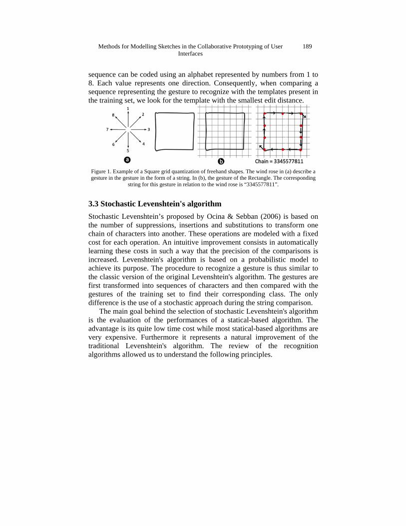
Figure 1 shows an example of the grid quantization of freehand shape. The features to be extracted from the raw data are based on the principle described by D. Llorens & Zamora (2008). The representation of the rectangle is superposed with a grid and the freehand drawing is quantized with respect to the grid nodes. Each grid node has 8 adjacent grid nodes and for each pair of adjacent nodes one out of 8 directions can be given (i.e: 1 for North, 2 for NorthEast, 3 for East, and so on). From the sequence of successive grid nodes, a sequence of directions can be derived. This
Methods
sequence 8. Each vsequence rthe trainin
Figure 1. Exgesture in th
3.3 StochStochasticthe numbechain of ccost for ealearning thincreased.achieve itthe classicfirst transfgestures odifference
The mis the evaadvantagevery expetraditionalalgorithms
s for Modellin
can be codevalue represrepresenting
ng set, we lo
xample of a Squhe gesture in the
string for th
hastic Levec Levenshteer of suppr
characters inach operatiohese costs i Levenshtes purpose. Tc version offormed intoof the traine is the use o
main goal behaluation of e is its quiteensive. Furtl Levenshts allowed u
ng Sketches inInt
ed using ansents one dg the gestur
ook for the t
uare grid quantie form of a strinhis gesture in re
enshtein's ein’s proposressions, innto another.on. An intuin such a wein's algoritThe procedf the originao sequencesning set to of a stochashind the selthe perform
e low time cthermore ittein's algos to underst
n the Collaborerfaces
n alphabet redirection. Cre to recogntemplate wi
ization of freehang. In (b), the gelation to the w
algorithmsed by Ocinsertions and. These ope
uitive improway that thethm is bas
dure to recogal Levenshts of charact
find their stic approaclection of stmances of
cost while mt represents
orithm. Thtand the foll
rative Prototyp
epresented bonsequently
nize with thith the small
and shapes. Theesture of the Re
wind rose is “334
m na & Sebbad substituti
erations are vement con
e precision ed on a prgnize a gestein's algoriters and the
correspondh during thetochastic Lea statical-b
most staticals a natural e review lowing prin
ping of User
by numbersy, when coe templateslest edit dis
e wind rose in (ectangle. The c45577811”.
an (2006) isions to tranmodeled w
nsists in autof the comprobabilistic
sture is thusthm. The gen compareding class. e string comevenshtein'sbased algorl-based algo
improvemof the r
nciples.
189
s from 1 to omparing a s present in stance.
(a) describe a orresponding
s based on nsform one with a fixed tomatically parisons is
model to s similar to estures are
ed with the The only
mparison. s algorithm rithm. The orithms are
ment of the recognition
190
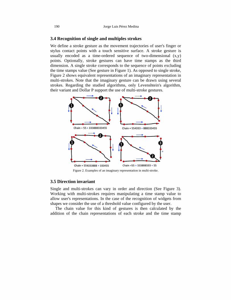
3.4 RecogWe definestylus conusually enpoints. Odimensionthe time stFigure 2 smulti-strokstrokes. Rtheir varia
3.5 DirecSingle anWorking allow usershapes we
The chaddition o
gnition of e a stroke gntact pointsncoded as
Optionally, n. A single tamps valueshows equivkes. Note t
Regarding tant and Doll
Figure 2. E
ction invard multi-strowith multi-r's represene consider thhain value of the chain
Jo
single andgesture as ths with a to
a time-ordstroke geststroke corree (See gestuvalent reprethat the imathe studied lar P suppor
Examples of an
riant okes can v-strokes req
ntations. In he use of a tfor this ki
n represent
orge Luis Pére
d multiplehe movemeouch sensitidered sequtures can hesponds to ture in Figureesentations oaginary ges
algorithmsrt the use of
imaginary repr
ary in ordequires manithe case of threshold vaind of gesttations of e
ez Medina
s strokesent trajectorive surface.uence of twhave time the sequence 1). As oppof an imaginture can bes, only Levf multi-strok
resentation in m
er and direipulating a
f the recognalue configutures is theeach stroke
ries of user'. A stroke wo-dimensistamps as
ce of pointsposed to sinnary repres
e drawn usivenshtein's ke gestures.
multi-stroke.
ction (See time stamp
nition of widured by the en calculat
e and the ti
s finger or gesture is
ional (x,y) the third
s excluding ngle stroke, entation in ing several algorithm,
.
Figure 3). p value to dgets from user.
ted by the ime stamp
Methods
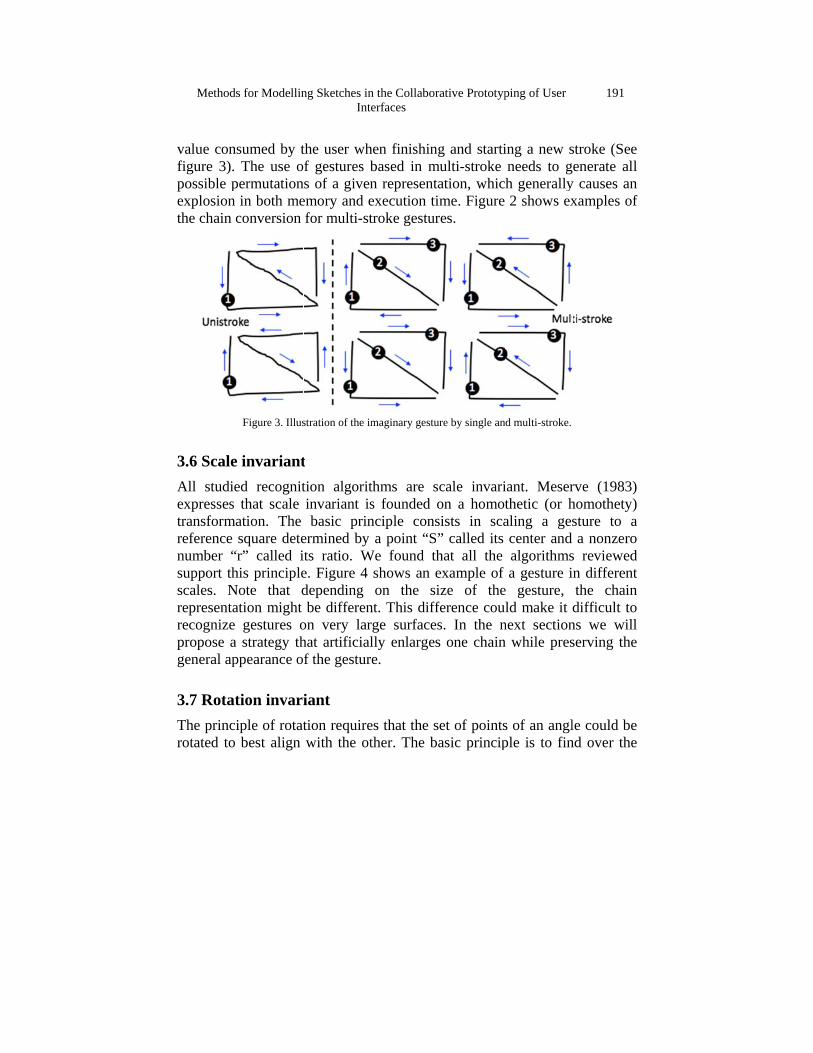
value configure 3). possible pexplosion the chain c
3.6 ScaleAll studieexpresses transformareference number “support thscales. Nrepresentarecognize propose ageneral ap
3.7 RotatThe princirotated to
s for Modellin
sumed by tThe use o
permutationin both me
conversion
Figure 3. Illus
e invarianted recognitthat scale
ation. The square dete
“r” called ihis principle
Note that dation might
gestures oa strategy thppearance o
tion invariiple of rotatbest align
ng Sketches inInt
the user whf gestures bs of a given
emory and efor multi-st
stration of the im
t tion algoritinvariant isbasic prin
ermined by ts ratio. We. Figure 4 depending be differen
on very larhat artificialf the gestur
iant tion requirewith the ot
n the Collaborerfaces
hen finishingbased in mn representaexecution titroke gestur
maginary gestu
thms are ss founded onciple cons
a point “S”We found th
shows an eon the si
nt. This diffrge surfaceslly enlargesre.
es that the sther. The ba
rative Prototyp
g and startimulti-stroke
ation, whichime. Figure res.
ure by single an
cale invarion a homotsists in sca” called its hat all the example of ize of theference cous. In the ns one chain
set of pointsasic princip
ping of User
ing a new sneeds to gh generally2 shows ex
d multi-stroke.
iant. Meserthetic (or haling a gescenter and algorithmsa gesture i
e gesture, ld make it
next sectionn while pres
s of an anglple is to fin
191
stroke (See enerate all
y causes an xamples of
rve (1983) homothety) sture to a a nonzero
s reviewed n different the chain difficult to
ns we will serving the
le could be nd over the
192
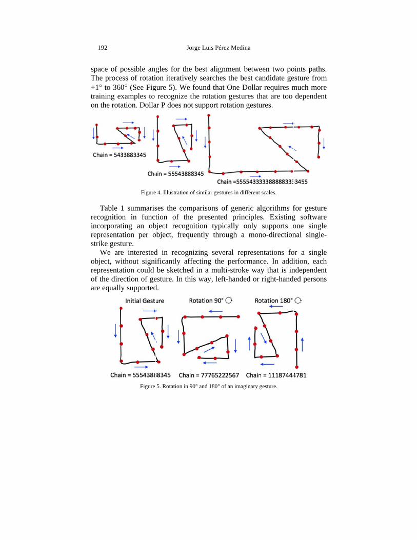
space of pThe proce+1° to 360training exon the rota
Table recognitioincorporatrepresentastrike gest
We areobject, wirepresentaof the direare equally
possible angess of rotati0° (See Figxamples to ation. Dolla
Figure
1 summarison in functting an obation per oture. e interestedithout signiation could ection of gey supported
Figure
Jo
gles for theon iterative
gure 5). We recognize t
ar P does no
e 4. Illustration o
ses the comtion of the
bject recognobject, frequ
d in recognificantly afbe sketched
esture. In thd.
5. Rotation in 9
orge Luis Pére
e best alignely searches
found that the rotation
ot support ro
of similar gestu
mparisons oe presentednition typicuently thro
nizing seveffecting the d in a mult
his way, left
90° and 180° of
ez Medina
nment betwes the best ca
One Dollarn gestures thotation gestu
ures in different
of generic ad principlecally only
ough a mon
eral represeperforman
ti-stroke wat-handed or
f an imaginary
een two poandidate ger requires mhat are too ures.
t scales.
algorithms fes. Existing
supports ono-direction
entations fonce. In addiay that is inr right-hand
gesture.
oints paths. esture from much more dependent
for gesture g software one single nal single-
or a single ition, each ndependent ed persons
Methods for Modelling Sketches in the Collaborative Prototyping of User Interfaces
193
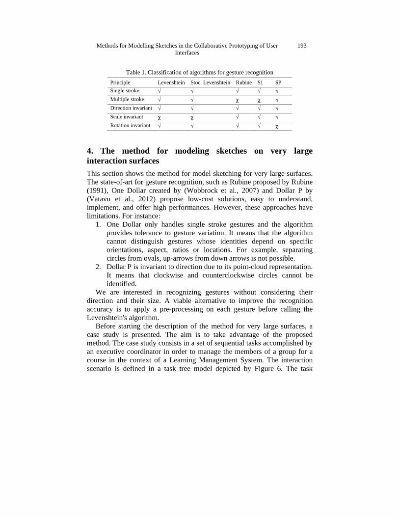
Table 1. Classification of algorithms for gesture recognition Principle Levenshtein Stoc. Levenshtein Rubine $1 $P Single stroke √ √ √ √ √ Multiple stroke √ √ χ χ √ Direction invariant √ √ √ √ √ Scale invariant χ χ √ √ √ Rotation invariant √ √ √ √ χ
4. The method for modeling sketches on very large interaction surfaces This section shows the method for model sketching for very large surfaces. The state-of-art for gesture recognition, such as Rubine proposed by Rubine (1991), One Dollar created by (Wobbrock et al., 2007) and Dollar P by (Vatavu et al., 2012) propose low-cost solutions, easy to understand, implement, and offer high performances. However, these approaches have limitations. For instance:
1. One Dollar only handles single stroke gestures and the algorithm provides tolerance to gesture variation. It means that the algorithm cannot distinguish gestures whose identities depend on specific orientations, aspect, ratios or locations. For example, separating circles from ovals, up-arrows from down arrows is not possible.
2. Dollar P is invariant to direction due to its point-cloud representation. It means that clockwise and counterclockwise circles cannot be identified.
We are interested in recognizing gestures without considering their direction and their size. A viable alternative to improve the recognition accuracy is to apply a pre-processing on each gesture before calling the Levenshtein's algorithm.
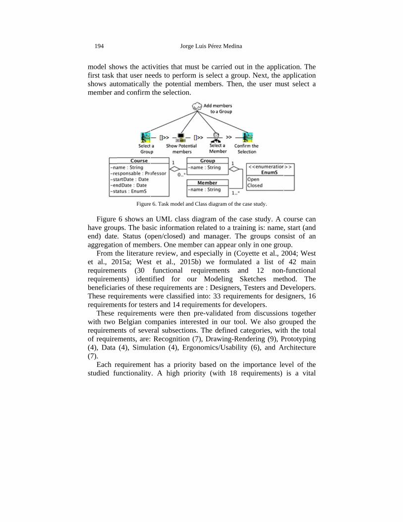
Before starting the description of the method for very large surfaces, a case study is presented. The aim is to take advantage of the proposed method. The case study consists in a set of sequential tasks accomplished by an executive coordinator in order to manage the members of a group for a course in the context of a Learning Management System. The interaction scenario is defined in a task tree model depicted by Figure 6. The task
194
model shofirst task tshows autmember a
Figure have grouend) dateaggregatio
From thet al., 20requiremerequiremebeneficiarThese reqrequireme
These with two requiremeof require(4), Data (7).
Each rstudied fu
ows the actthat user netomatically
and confirm
Figure
6 shows anups. The bas. Status (oon of membhe literature
015a; Westents (30 ents) identries of thesequirements wents for testerequiremenBelgian co
ents of seveements, are:
(4), Simul
requirementunctionality
Jo
ivities that eeds to perf
the potentthe selectio
e 6. Task model
n UML clasic informatopen/closed)bers. One me review, ant et al., 2functional
tified for e requiremenwere classifers and 14 rnts were theompanies ineral subsect Recognitioation (4), E
t has a prioy. A high p
orge Luis Pére
must be caform is seletial memberon.
l and Class diag
ss diagram tion related ) and manaember can and especial015b) we
requiremour Mod
nts are : Defied into: 3requirementen pre-validnterested inions. The don (7), DrawErgonomics
ority based priority (w
ez Medina
arried out inect a group. rs. Then, th
gram of the case
of the caseto a trainin
ager. The gappear onlylly in (Coyeformulated
ments and deling Skeesigners, Te3 requiremets for develodated from
n our tool. Wdefined catewing-Rendes/Usability
on the imwith 18 requ
n the applicNext, the a
he user mu
e study.
e study. A cng is: namegroups con
y in one grouette et al., 2d a list of
12 non-etches metesters and Dents for desopers.
m discussionWe also gregories, witering (9), P(6), and A
mportance leuirements)
cation. The application
ust select a
course can , start (and
nsist of an up.
2004; West f 42 main -functional thod. The
Developers. signers, 16
ns together rouped the th the total Prototyping
Architecture
evel of the is a vital
Methods for Modelling Sketches in the Collaborative Prototyping of User Interfaces
195
function for the tool, a medium priority (with 19 requirements) is a useful functionality but not indispensable, finally a low priority (with 5 requirements) is a functionality regarded as an accessory.
Most of the requirements for the proper functioning of UsiSketch are undoubtedly those in categories Recognition and Drawing-Rendering. Without them, the tool could not achieve its main objective. The requirements of categories Ergonomics/usability and Architecture are essentially non-functional. For reasons of space, the presentation of all the requirements is beyond the scope of this document, but one example is shown in table 2.
Table 2. An example of one requeriment for recognition Number: 5 Priority: Medium
Type: Non-Functional Responsible: ZZ Description: Composition rules (or grammar) must be specified outside the software code Motivation: Set new rules without touching the source code; allows great flexibility of the tool in the definition of the compositions; prevents the designer from having to adapt to the rules of composition which do not suit it Scenario: New widget to be defined; changing a composition rule (or grammar) clearer for the designer Beneficiary: Designer Prerequisites: Requirement 2 (the tool must be able to combine simple forms in a more complex form or widget, according to pre-established rules. Each time a new form is added to a window, the software must check whether it is possible to combine it with other forms)
From these objectives, we describe our method for model sketching for
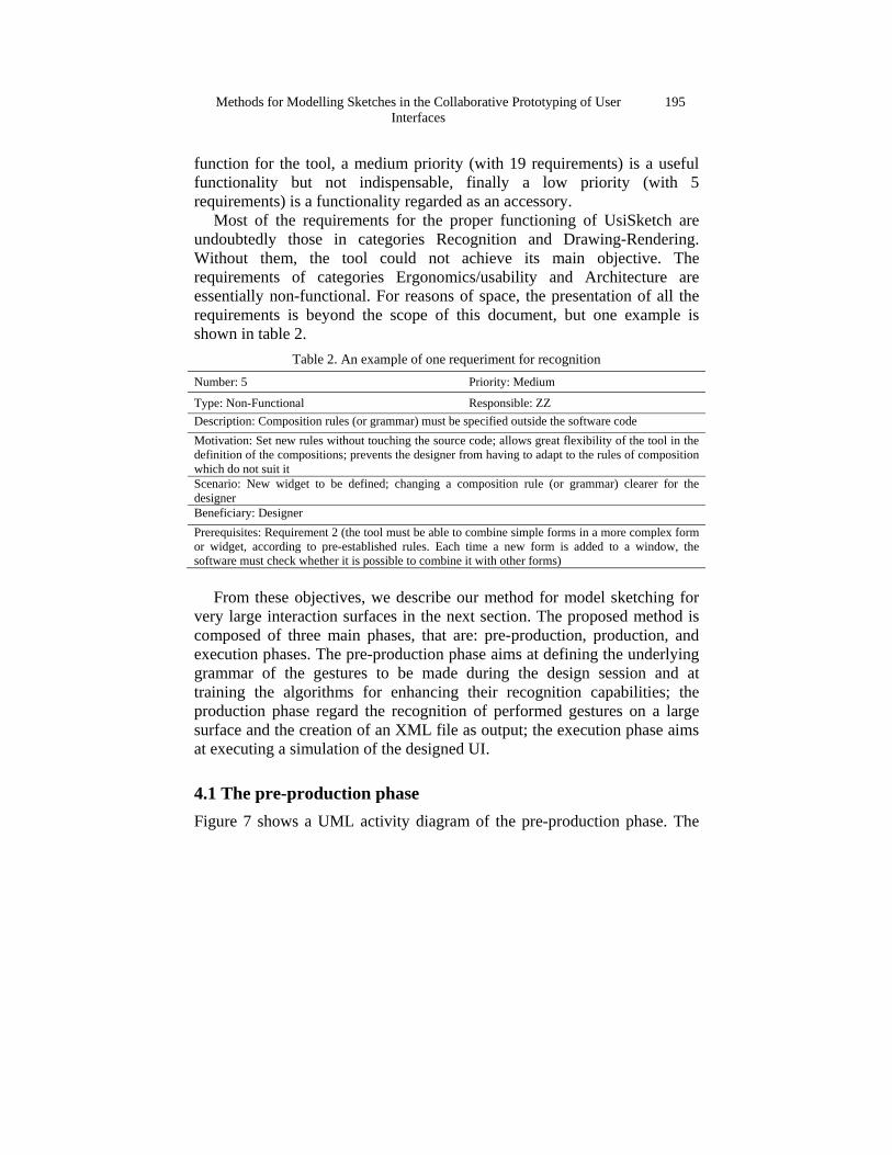
very large interaction surfaces in the next section. The proposed method is composed of three main phases, that are: pre-production, production, and execution phases. The pre-production phase aims at defining the underlying grammar of the gestures to be made during the design session and at training the algorithms for enhancing their recognition capabilities; the production phase regard the recognition of performed gestures on a large surface and the creation of an XML file as output; the execution phase aims at executing a simulation of the designed UI.
4.1 The pre-production phase Figure 7 shows a UML activity diagram of the pre-production phase. The
196
block ofclassificatconfigure production
4.1.1 DefiThe contesimpler sh
f pre-prodution of ske
the applican also requi
Figure 7. Pre
ine grammaextual gramhapes. Thes
Jo
uction alloetches. Thation for wires a trainin
e-production and
ar mmars are ue forms ma
orge Luis Pére
ows definie “Pre-pro
working withng step.
d production ph
used to defay be pre-dr
ez Medina
ing the goduction phh a specific
hases for Mode
fine forms rawn or draw
grammar ahase” is rec set of wid
ling Sketches.
as a compwn and reco
and some equired to dgets. Pre-
position of ognized by
Methods
a pattern grammar, “<form1>complex f
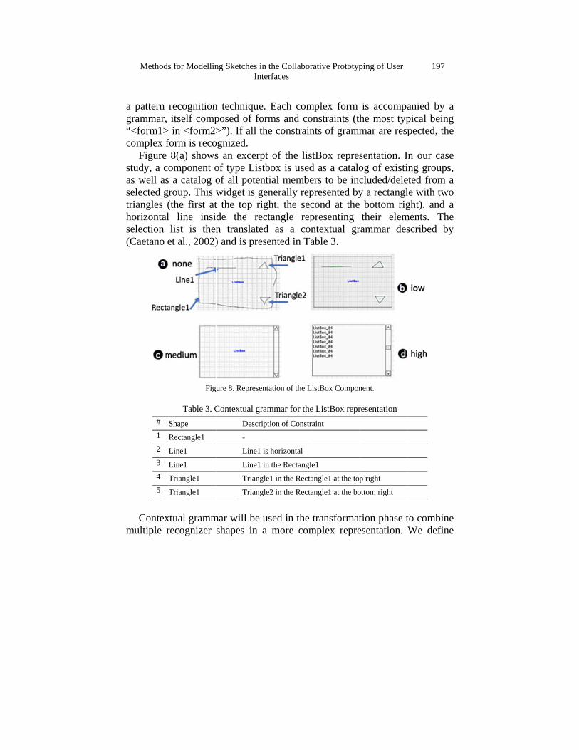
Figure study, a cas well asselected gtriangles (horizontalselection (Caetano e
#
1
2
3
4
5
Contex
multiple r
s for Modellin
recognitionitself comp
> in <form2>form is reco8(a) showsomponent o
s a catalog ogroup. This w(the first atl line insilist is then
et al., 2002)
Figu
Table 3. CShape
Rectangle1
Line1
Line1
Triangle1
Triangle1
xtual grammrecognizer
ng Sketches inInt
n technique.posed of fo>”). If all th
ognized. s an excerpof type Listof all potenwidget is get the top rigde the recn translated) and is pres
ure 8. Represen
Contextual graDescrip
-
Line1 i
Line1 i
Triangl
Triangl
mar will be ushapes in a
n the Collaborerfaces
. Each comrms and cohe constrain
pt of the listbox is usedntial membeenerally repght, the secctangle repd as a consented in Ta
ntation of the L
ammar for theption of Constra
is horizontal
in the Rectangle
le1 in the Recta
le2 in the Recta
used in the a more com
rative Prototyp
mplex form onstraints (thnts of gramm
tBox represd as a cataloers to be incpresented bycond at the presenting ntextual grable 3.
istBox Compon
e ListBox repraint
e1
angle1 at the top
angle1 at the bo
transformatmplex repre
ping of User
is accompahe most typmar are resp
sentation. Iog of existicluded/deley a rectangl
bottom rigtheir elem
rammar des
nent.
resentation
p right
ottom right
tion phase tesentation. W
197
anied by a pical being pected, the
n our case ng groups,
eted from a le with two ght), and a
ments. The scribed by
to combine We define
198
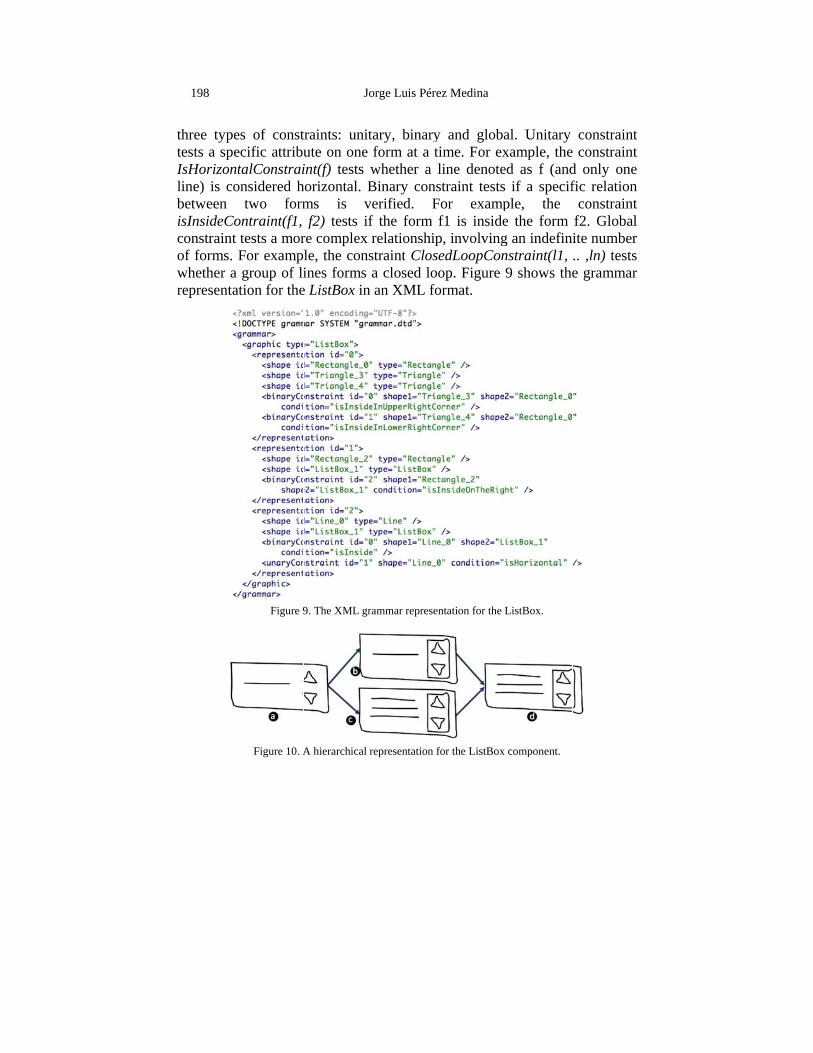
three typetests a speIsHorizonline) is cobetween isInsideCoconstraint of forms. whether arepresenta
es of constecific attribu
ntalConstraionsidered h
two formontraint(f1, tests a morFor examp
a group of liation for the
Figure 9
Figure 10. A
Jo
traints: unitute on one int(f) tests w
horizontal. Bms is vf2) tests if
re complex le, the consines forms
e ListBox in
9. The XML gr
A hierarchical r
orge Luis Pére
tary, binaryform at a twhether a lBinary consverified. Ff the form relationshipstraint Closa closed looan XML fo
rammar represen
representation f
ez Medina
y and globatime. For exline denotestraint tests
For exampf1 is insidep, involvingedLoopConop. Figure ormat.
ntation for the L
for the ListBox
al. Unitary xample, theed as f (and if a specifple, the e the form g an indefinnstraint(l1, 9 shows the
ListBox.
component.
constraint constraint
d only one fic relation
constraint f2. Global ite number .. ,ln) tests e grammar
Methods for Modelling Sketches in the Collaborative Prototyping of User Interfaces
199
Our grammar specification supports multiple representations of a specific widget. Figure 10 shows a hierarchical representation of the ListBox component. On the hierarchical representation many representations can be combined to define new representations. At the top (Part a of figure) of the hierarchical representation the ListBox component is represented by a rectangle, two triangles and a line. Next, two additional representations (Parts b and c of the figure) have been created to specialize the original representation of ListBox. Finally, these representations can be combined into a more complex representation of ListBox.
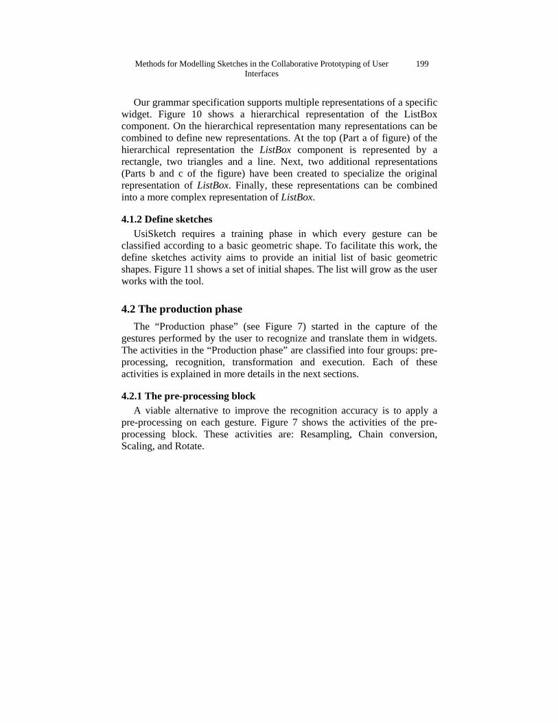
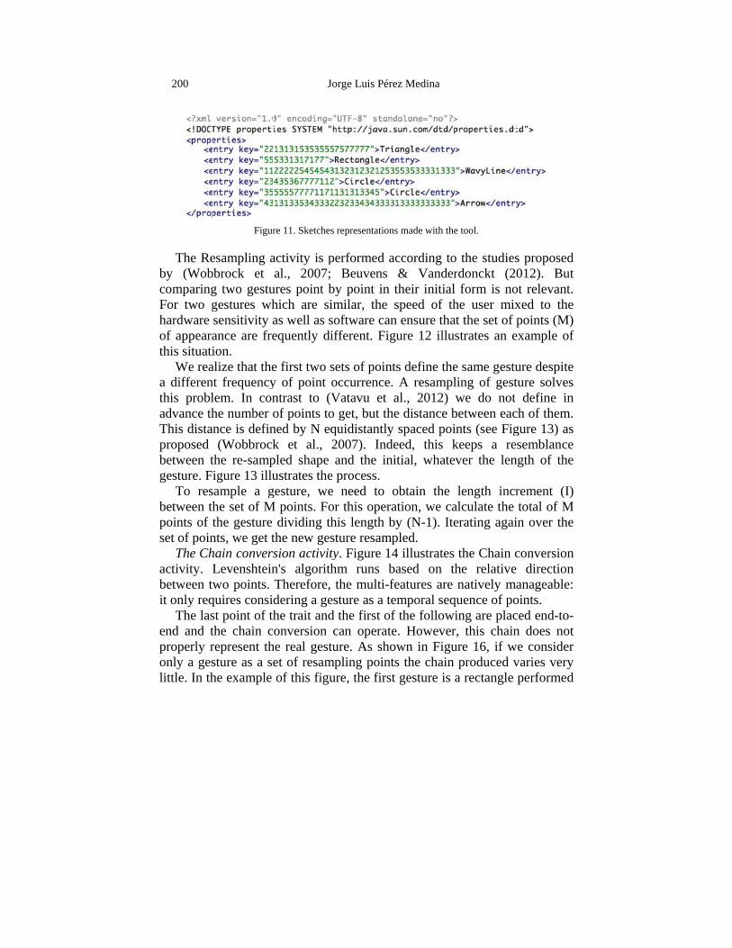
4.1.2 Define sketches UsiSketch requires a training phase in which every gesture can be
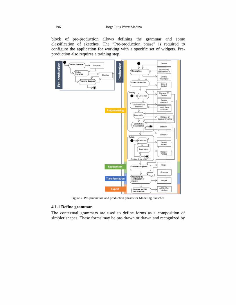
classified according to a basic geometric shape. To facilitate this work, the define sketches activity aims to provide an initial list of basic geometric shapes. Figure 11 shows a set of initial shapes. The list will grow as the user works with the tool.
4.2 The production phase The “Production phase” (see Figure 7) started in the capture of the
gestures performed by the user to recognize and translate them in widgets. The activities in the “Production phase” are classified into four groups: pre-processing, recognition, transformation and execution. Each of these activities is explained in more details in the next sections.
4.2.1 The pre-processing block A viable alternative to improve the recognition accuracy is to apply a
pre-processing on each gesture. Figure 7 shows the activities of the pre-processing block. These activities are: Resampling, Chain conversion, Scaling, and Rotate.
200
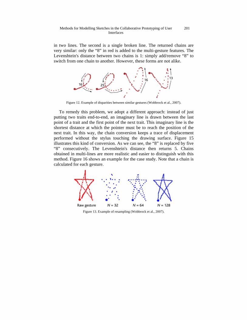
The Reby (WobcomparingFor two ghardware of appearathis situati
We reaa differenthis probladvance thThis distaproposed between tgesture. F
To resbetween thpoints of tset of poin
The Chactivity. Lbetween twit only req
The lasend and tproperly ronly a geslittle. In th
Figur
esampling abbrock et g two gestugestures whsensitivity aance are freion.
alize that thent frequencylem. In conhe number once is defin(Wobbrock
the re-sampigure 13 illu
sample a ghe set of Mthe gesture nts, we get thain conversLevenshteinwo points.
quires consist point of ththe chain crepresent thsture as a sehe example
Jo
re 11. Sketches
activity is pal., 2007;
ures point bhich are simas well as sequently di
e first two sy of point ontrast to (Vof points toned by N eqk et al., 2pled shape ustrates the
gesture, we M points. Fo
dividing ththe new gession activityn's algorithTherefore, dering a geshe trait andonversion c
he real gestuet of resamof this figu
orge Luis Pére
representation
performed aBeuvens
by point in tmilar, the oftware canfferent. Fig
sets of pointoccurrence. Vatavu et ao get, but thequidistantly 2007). Indeand the iniprocess. need to o
or this operahis length bsture resampy. Figure 14hm runs bthe multi-festure as a te
d the first ofcan operateure. As sho
mpling pointure, the first
ez Medina
s made with the
according to& Vander
their initialspeed of th
n ensure thagure 12 illu
ts define theA resampl
al., 2012) e distance bspaced poi
eed, this kitial, whate
obtain the ation, we caby (N-1). Itepled. 4 illustratesbased on thfeatures are emporal seqf the followie. Howeverown in Figus the chain t gesture is a
e tool.
o the studiesrdonckt (2 form is nohe user mixat the set of strates an e
e same gestuling of gestwe do not
between eacints (see Figkeeps a rever the len
length incralculate the erating agai
the Chain che relativenatively m
quence of poing are placr, this chainure 16, if w
produced va rectangle
s proposed 012). But
ot relevant. xed to the points (M)
example of
ure despite ture solves
define in ch of them. gure 13) as esemblance ngth of the
rement (I) total of M
in over the
conversion e direction
manageable: oints. ced end-to-n does not
we consider varies very performed
Methods
in two linvery similLevenshteswitch fro
Figu
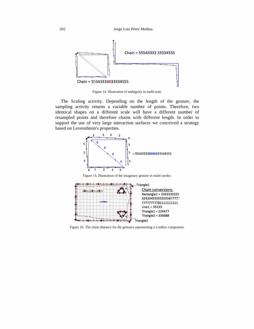
To remputting twpoint of a shortest dnext trait. performedillustrates “8” conseobtained imethod. Fcalculated
s for Modellin
nes. The selar: only theein's distancom one chain
ure 12. Example
medy this prwo traits end
trait and thdistance at w
In this wad without tthis kind of
ecutively. in multi-line
Figure 16 shd for each ge
Figure
ng Sketches inInt
cond is a se “8” in redce between n to another
e of disparities
roblem, wed-to-end, an
he first poinwhich the pay, the chainthe stylus f conversionThe Levenes are more
hows an exaesture.
13. Example o
n the Collaborerfaces
single broked is added ttwo chains
r. However
between simila
e adopt a din imaginary
nt of the nexpointer musn conversiotouching tn. As we canshtein's die realistic anample for th
f resampling (W
rative Prototyp
en line. Tho the multi
s is 1: simp, these form
ar gestures (Wob
ifferent appy line is drxt trait. Thisst be to reacon keeps a he drawing
an see, the “istance thend easier to
he case study
Wobbrock et al.
ping of User
he returned -gesture fea
ply add/remms are not al
bbrock et al., 2
proach: insterawn betwes imaginarych the posittrace of disg surface. “8” is replacn returns
o distinguishy. Note that
, 2007).
201
chains are atures. The ove “8” to like.
007).
ead of just en the last
y line is the tion of the splacement Figure 15
ced by five 5. Chains h with this t a chain is
202
The Scsampling identical resampledsupport thbased on L
Fig
Fi
caling activactivity reshapes on
d points anhe use of veLevenshtein
Figure 15
gure 16. The ch
Jo
igure 14. Illustr
vity. Depeeturns a va
a differennd thereforeery large inn's propertie
5. Illustration o
ain distance for
orge Luis Pére
ration of ambigu
nding on ariable numnt scale wie chains winteraction ses.
of the imaginary
r the gestures re
ez Medina
uity in multi-tra
the length mber of poill have a ith differensurfaces we
y gesture in mu
epresenting a L
ait.
of the geoints. There
different nnt length. In
conceived
lti-stroke.
istBox compon
esture, the efore, two number of n order to a strategy
nent.
Methods
The Lebetween twtwo string
Indeed,of as masuppressiodifference
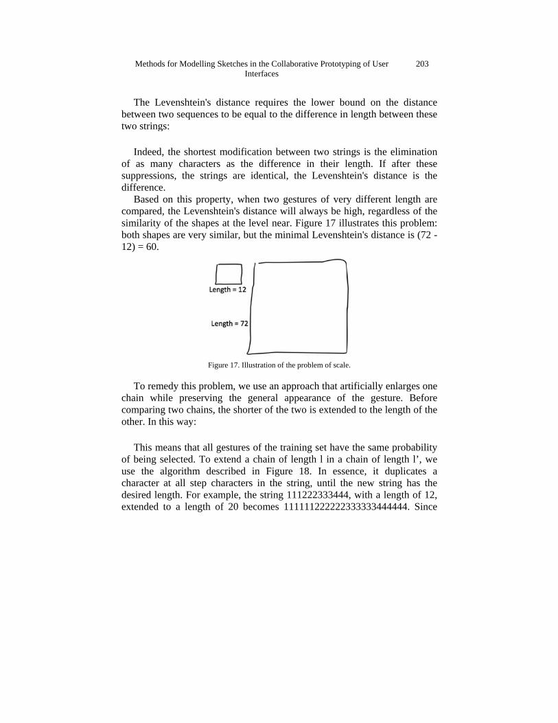
Based comparedsimilarity both shape12) = 60.
To remchain whcomparingother. In th
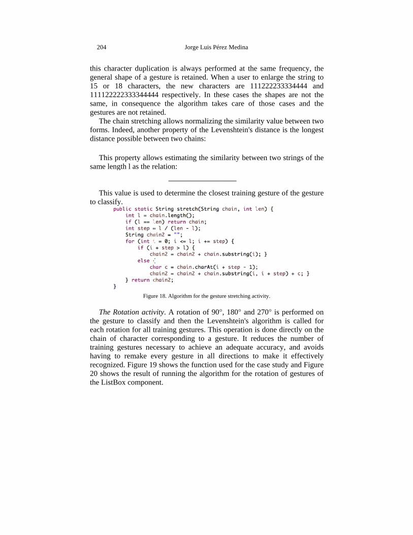
This mof being suse the acharacter desired lenextended
s for Modellin
evenshtein'swo sequenc
gs:
, the shorteany charactons, the stre. on this pro, the Levenof the shap
es are very
F
medy this prohile preservg two chainhis way:
means that alselected. Toalgorithm dat all step ngth. For exto a length
ng Sketches inInt
s distance ces to be equ
est modificaters as the rings are id
operty, whenshtein's dispes at the lesimilar, but
Figure 17. Illus
oblem, we uving the gens, the shorte
ll gestures oo extend a cdescribed icharacters
xample, theh of 20 bec
n the Collaborerfaces
requires thual to the d
ation betwedifference
dentical, th
n two gestustance will aevel near. Ft the minim
stration of the p
use an approeneral appeer of the tw
of the trainichain of lenn Figure 1in the strin
e string 111comes 1111
rative Prototyp
he lower boifference in
en two strinin their l
he Levensht
ures of veryalways be higure 17 ill
mal Levensh
problem of scale
oach that arearance of
wo is extende
ing set havength l in a c18. In esseng, until th
12223334441112222223
ping of User
ound on thn length betw
ngs is the elength. If atein's distan
y different high, regardlustrates thitein's distan
e.
rtificially enthe gestur
ed to the len
e the same pchain of lenence, it duhe new strin4, with a len3333334444
203
he distance ween these
elimination after these nce is the
length are dless of the s problem: nce is (72 -
nlarges one re. Before ngth of the
probability ngth l’, we uplicates a ng has the ngth of 12, 444. Since
204
this charageneral sh15 or 1811112222same, in gestures a
The chforms. Inddistance p
This prsame leng
This vato classify
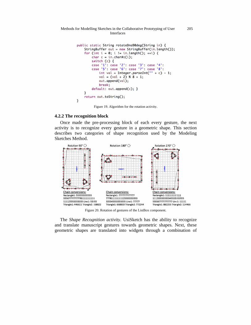
The Rothe gestureach rotatchain of training ghaving torecognized20 shows the ListBo
acter duplicahape of a ge8 character233334444consequenc
are not retainain stretchindeed, anothepossible betw
roperty allowgth l as the r
alue is usedy.
Figur
otation activre to classifion for all tcharacter c
gestures neco remake evd. Figure 19the result o
ox compone
Jo
ation is alwesture is retrs, the new
44 respectivce the algoned. ng allows ner property ween two ch
ws estimatirelation:
d to determin
re 18. Algorithm
vity. A rotatfy and thentraining gescorrespondincessary to very gestur9 shows theof running tent.
orge Luis Pére
ways perfortained. Whew characte
vely. In theorithm take
normalizingof the Lev
hains:
ing the simi
ne the close
m for the gestur
tion of 90°n the Levenstures. This ng to a gesachieve an re in all de function uthe algorith
ez Medina
rmed at theen a user toers are 11ese cases thes care of
the similarivenshtein's d
ilarity betw
est training
re stretching ac
, 180° and nshtein's aloperation isture. It re
adequate irections tosed for the
hm for the r
e same freqo enlarge th122223333
he shapes athose case
ity value bedistance is t
een two str
gesture of t
tivity.
270° is perlgorithm is s done direduces the naccuracy, ao make it case study
rotation of g
quency, the he string to 34444 and are not the es and the
etween two the longest
ings of the
the gesture
rformed on called for
ctly on the number of and avoids effectively and Figure gestures of
Methods
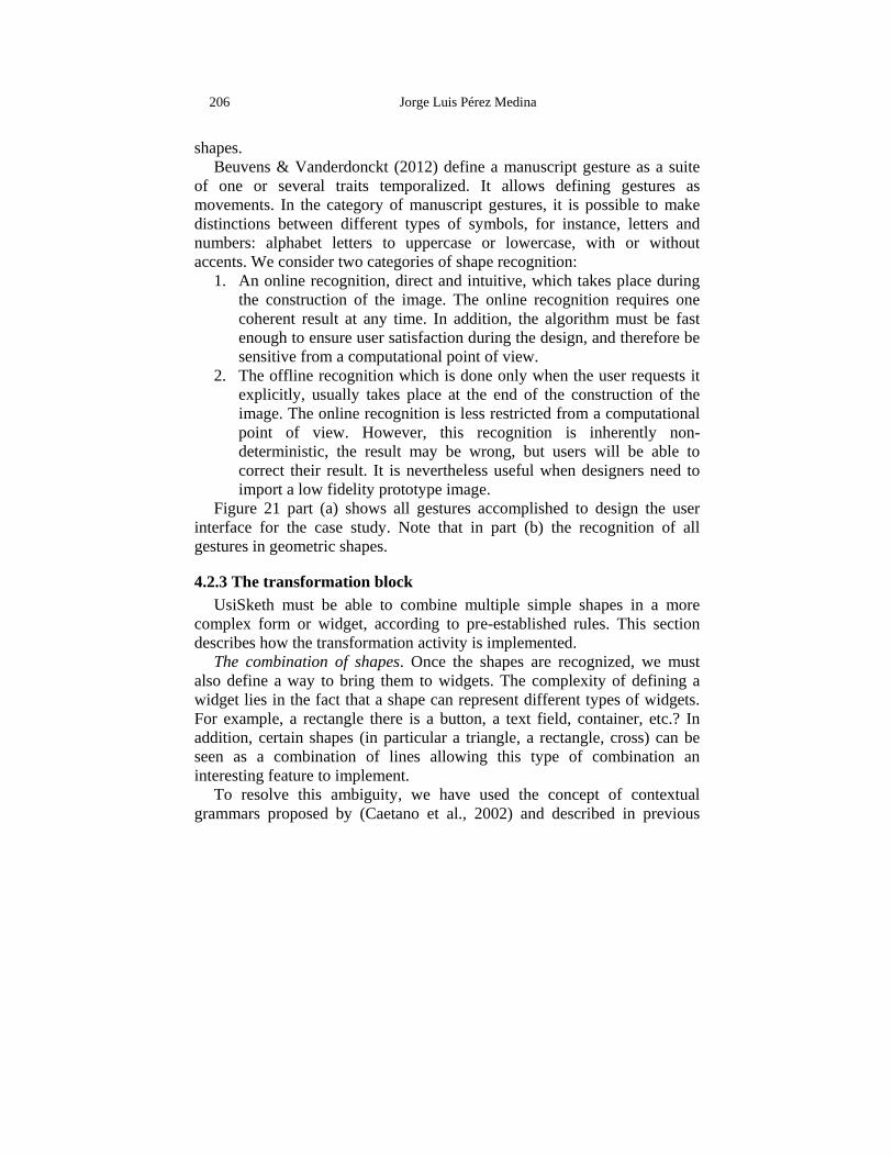
4.2.2 The Once m
activity isdescribes Sketches M
The Shand translgeometric
s for Modellin
recognitiomade the ps to recogn
two categMethod.
Figure
hape Recoglate manusc
c shapes ar
ng Sketches inInt
Figure 19. Algo
n block pre-processinize every ggories of s
e 20. Rotation o
gnition activcript gesturre translated
n the Collaborerfaces
orithm for the r
ing block ogesture in ashape recog
of gestures of th
vity. UsiSkeres towardsd into wid
rative Prototyp
rotation activity
of each evea geometricgnition use
he ListBox comp
etch has thes geometricdgets throug
ping of User
y.
ery gesturec shape. Thed by the
ponent.
e ability toc shapes. Ngh a comb
205
e, the next his section
Modeling
recognize Next, these bination of
206 Jorge Luis Pérez Medina
shapes. Beuvens & Vanderdonckt (2012) define a manuscript gesture as a suite
of one or several traits temporalized. It allows defining gestures as movements. In the category of manuscript gestures, it is possible to make distinctions between different types of symbols, for instance, letters and numbers: alphabet letters to uppercase or lowercase, with or without accents. We consider two categories of shape recognition:
1. An online recognition, direct and intuitive, which takes place during the construction of the image. The online recognition requires one coherent result at any time. In addition, the algorithm must be fast enough to ensure user satisfaction during the design, and therefore be sensitive from a computational point of view.
2. The offline recognition which is done only when the user requests it explicitly, usually takes place at the end of the construction of the image. The online recognition is less restricted from a computational point of view. However, this recognition is inherently non-deterministic, the result may be wrong, but users will be able to correct their result. It is nevertheless useful when designers need to import a low fidelity prototype image.
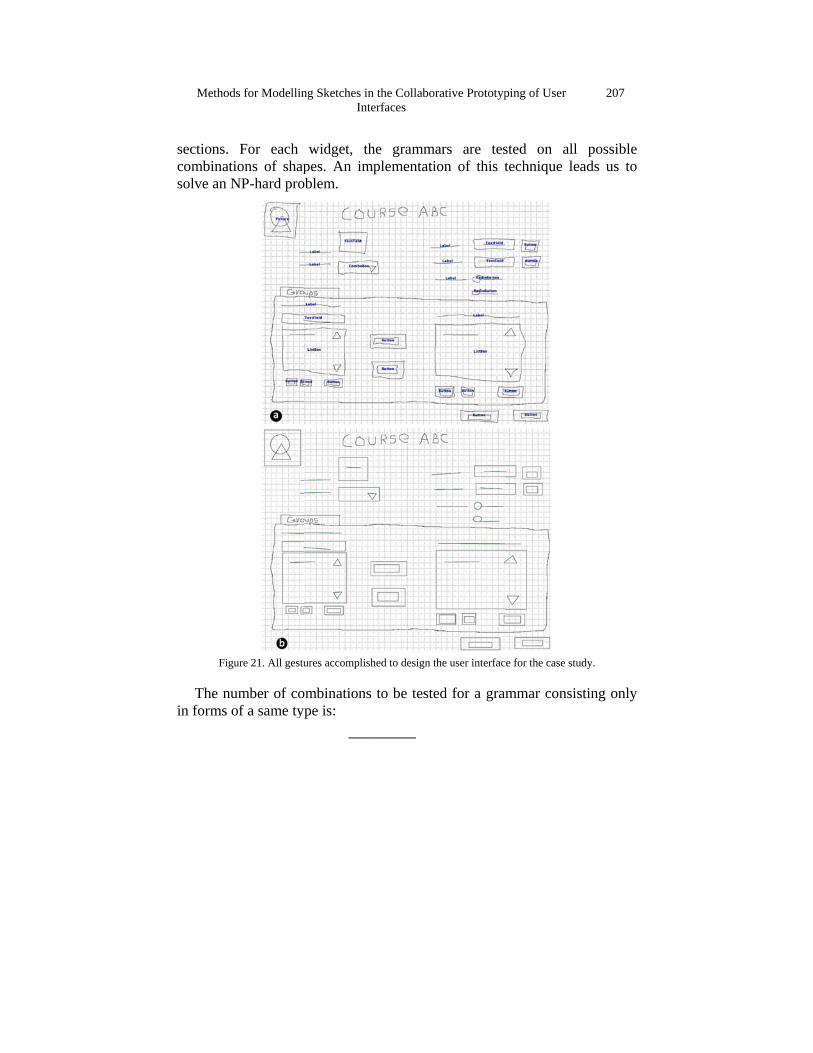
Figure 21 part (a) shows all gestures accomplished to design the user interface for the case study. Note that in part (b) the recognition of all gestures in geometric shapes.
4.2.3 The transformation block UsiSketh must be able to combine multiple simple shapes in a more
complex form or widget, according to pre-established rules. This section describes how the transformation activity is implemented.
The combination of shapes. Once the shapes are recognized, we must also define a way to bring them to widgets. The complexity of defining a widget lies in the fact that a shape can represent different types of widgets. For example, a rectangle there is a button, a text field, container, etc.? In addition, certain shapes (in particular a triangle, a rectangle, cross) can be seen as a combination of lines allowing this type of combination an interesting feature to implement.
To resolve this ambiguity, we have used the concept of contextual grammars proposed by (Caetano et al., 2002) and described in previous
Methods
sections. combinatisolve an N
Figu
The nuin forms o
s for Modellin
For each ions of shapNP-hard pro
ure 21. All gestu
umber of coof a same ty
ng Sketches inInt
widget, thpes. An im
oblem.
ures accomplish
ombinationsype is:
n the Collaborerfaces
he grammamplementatio
hed to design th
s to be teste
rative Prototyp
ars are teson of this t
he user interfac
ed for a gram
ping of User
sted on altechnique l
e for the case st
mmar cons
207
ll possible leads us to
tudy.
isting only
208 Jorge Luis Pérez Medina
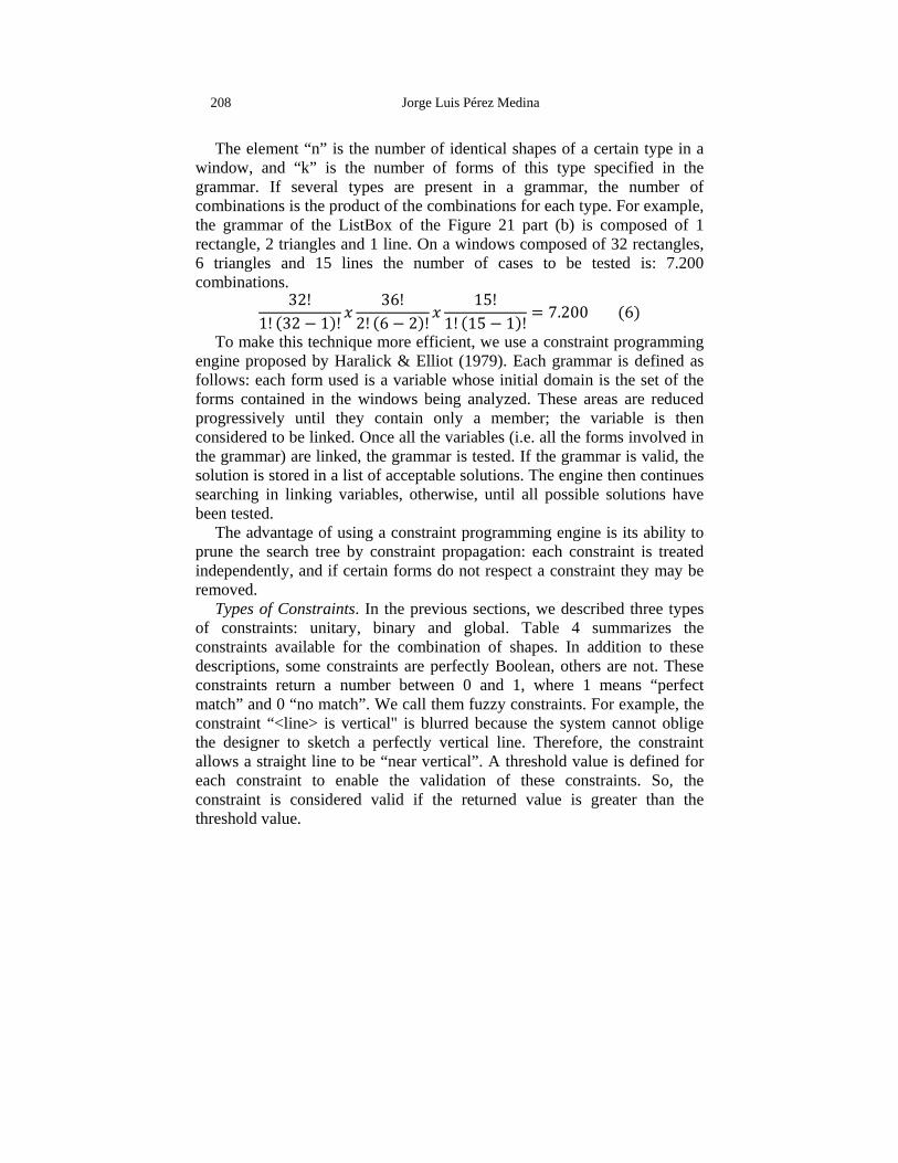
The element “n” is the number of identical shapes of a certain type in a window, and “k” is the number of forms of this type specified in the grammar. If several types are present in a grammar, the number of combinations is the product of the combinations for each type. For example, the grammar of the ListBox of the Figure 21 part (b) is composed of 1 rectangle, 2 triangles and 1 line. On a windows composed of 32 rectangles, 6 triangles and 15 lines the number of cases to be tested is: 7.200 combinations. 32!1! 32 1 ! 36!2! 6 2 ! 15!1! 15 1 ! 7.200 6
To make this technique more efficient, we use a constraint programming engine proposed by Haralick & Elliot (1979). Each grammar is defined as follows: each form used is a variable whose initial domain is the set of the forms contained in the windows being analyzed. These areas are reduced progressively until they contain only a member; the variable is then considered to be linked. Once all the variables (i.e. all the forms involved in the grammar) are linked, the grammar is tested. If the grammar is valid, the solution is stored in a list of acceptable solutions. The engine then continues searching in linking variables, otherwise, until all possible solutions have been tested.
The advantage of using a constraint programming engine is its ability to prune the search tree by constraint propagation: each constraint is treated independently, and if certain forms do not respect a constraint they may be removed.
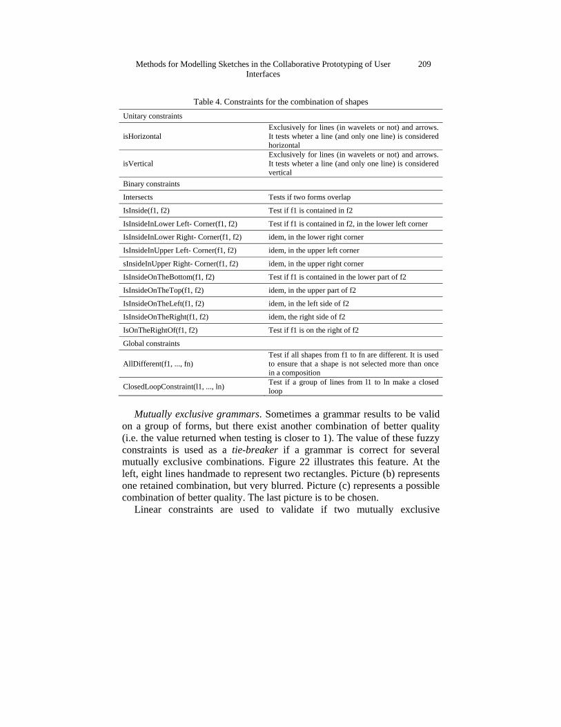
Types of Constraints. In the previous sections, we described three types of constraints: unitary, binary and global. Table 4 summarizes the constraints available for the combination of shapes. In addition to these descriptions, some constraints are perfectly Boolean, others are not. These constraints return a number between 0 and 1, where 1 means “perfect match” and 0 “no match”. We call them fuzzy constraints. For example, the constraint “<line> is vertical" is blurred because the system cannot oblige the designer to sketch a perfectly vertical line. Therefore, the constraint allows a straight line to be “near vertical”. A threshold value is defined for each constraint to enable the validation of these constraints. So, the constraint is considered valid if the returned value is greater than the threshold value.
Methods for Modelling Sketches in the Collaborative Prototyping of User Interfaces
209
Table 4. Constraints for the combination of shapes Unitary constraints
isHorizontal Exclusively for lines (in wavelets or not) and arrows. It tests wheter a line (and only one line) is considered horizontal
isVertical Exclusively for lines (in wavelets or not) and arrows. It tests wheter a line (and only one line) is considered vertical
Binary constraints
Intersects Tests if two forms overlap
IsInside(f1, f2) Test if f1 is contained in f2
IsInsideInLower Left- Corner(f1, f2) Test if f1 is contained in f2, in the lower left corner
IsInsideInLower Right- Corner(f1, f2) idem, in the lower right corner
IsInsideInUpper Left- Corner(f1, f2) idem, in the upper left corner
sInsideInUpper Right- Corner(f1, f2) idem, in the upper right corner
IsInsideOnTheBottom(f1, f2) Test if f1 is contained in the lower part of f2
IsInsideOnTheTop(f1, f2) idem, in the upper part of f2
IsInsideOnTheLeft(f1, f2) idem, in the left side of f2
IsInsideOnTheRight(f1, f2) idem, the right side of f2
IsOnTheRightOf(f1, f2) Test if f1 is on the right of f2
Global constraints
AllDifferent(f1, ..., fn) Test if all shapes from f1 to fn are different. It is used to ensure that a shape is not selected more than once in a composition
ClosedLoopConstraint(l1, ..., ln) Test if a group of lines from l1 to ln make a closed loop
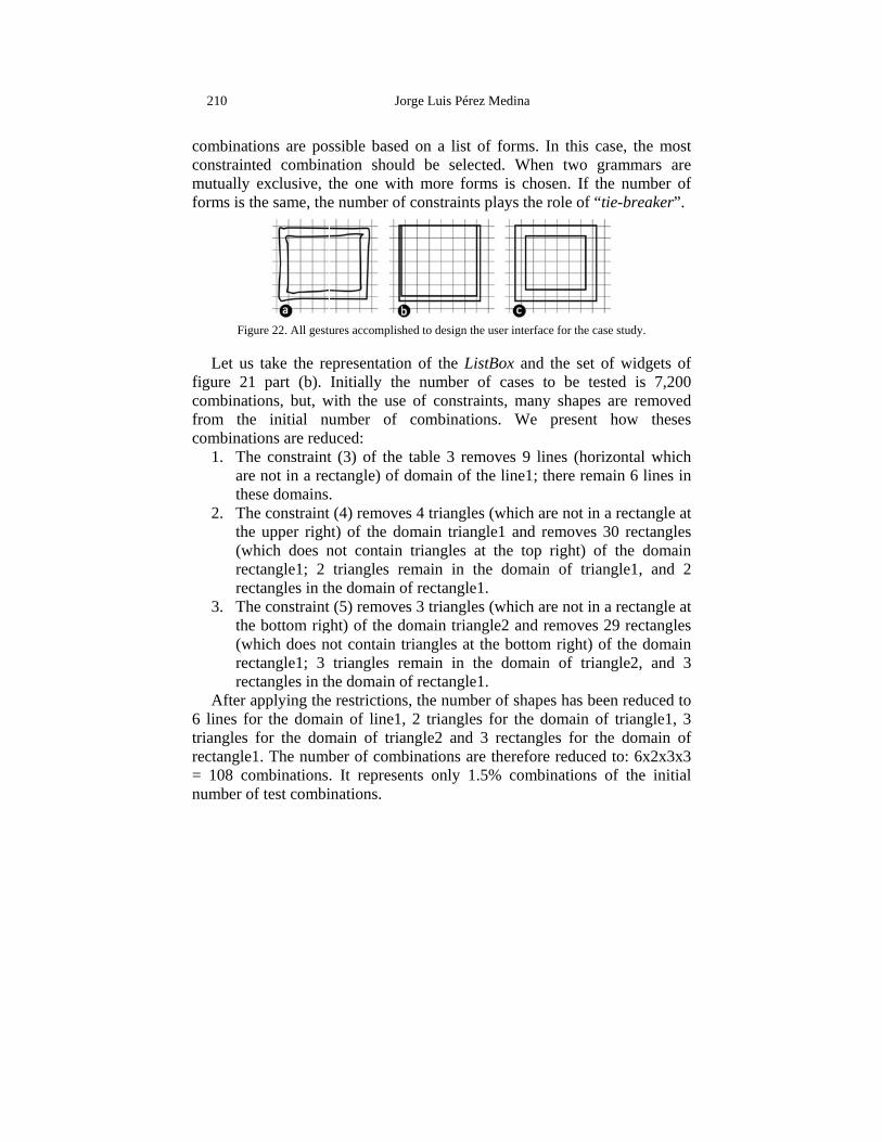
Mutually exclusive grammars. Sometimes a grammar results to be valid
on a group of forms, but there exist another combination of better quality (i.e. the value returned when testing is closer to 1). The value of these fuzzy constraints is used as a tie-breaker if a grammar is correct for several mutually exclusive combinations. Figure 22 illustrates this feature. At the left, eight lines handmade to represent two rectangles. Picture (b) represents one retained combination, but very blurred. Picture (c) represents a possible combination of better quality. The last picture is to be chosen.
Linear constraints are used to validate if two mutually exclusive
210
combinaticonstraintmutually forms is th
Figu
Let us figure 21 combinatifrom the combinati
1. Theare thes
2. Thethe (whrectrect
3. Thethe (whrectrect
After a6 lines fotriangles frectangle1= 108 comnumber of
ions are posed combinexclusive, the same, the
ure 22. All gestu
take the repart (b).
ions, but, w initial nuions are redue constraintnot in a rec
se domainse constraint upper righ
hich does ntangle1; 2 tangles in the constraint bottom rig
hich does ntangle1; 3 tangles in th
applying ther the domafor the dom1. The numbmbinationsf test combi
Jo
ssible basednation shouthe one wite number of
ures accomplish
epresentatioInitially th
with the useumber of uced: t (3) of thectangle) of . t (4) removeht) of the donot containtriangles r
he domain ot (5) removeght) of the dnot contain t
triangles rhe domain oe restrictionain of line1main of triaber of comb. It represeinations.
orge Luis Pére
d on a list ld be selecth more forf constraints
hed to design th
on of the Lihe number e of constra
combinati
table 3 remdomain of
es 4 triangleomain trian
n triangles aremain in tof rectanglees 3 triangledomain triantriangles at remain in tof rectangles, the numb, 2 triangleangle2 and binations arents only 1
ez Medina
of forms. Icted. Whenrms is choss plays the r
he user interfac
istBox andof cases to
aints, manyons. We
moves 9 linthe line1; th
es (which arngle1 and reat the top the domaine1. es (which arngle2 and rthe bottom
the domaine1. ber of shapees for the d
3 rectanglre therefore.5% combi
In this casen two gramsen. If the role of “tie-
e for the case st
the set of wo be tested
y shapes arepresent ho
nes (horizonhere remain
re not in a removes 30 right) of th
n of triangl
re not in a rremoves 29
m right) of tn of triangl
es has been omain of tres for the
e reduced toinations of
e, the most mmars are number of -breaker”.
tudy.
widgets of d is 7,200 e removed ow theses
ntal which n 6 lines in
ectangle at rectangles
he domain le1, and 2
ectangle at rectangles
the domain le2, and 3
reduced to riangle1, 3 domain of
o: 6x2x3x3 the initial
Methods
4.2.4 The This se
project in Consortiumany new without re(e.g., HTM
The deallow youdesigner. format. DVanderdon
s for Modellin
Figure 2
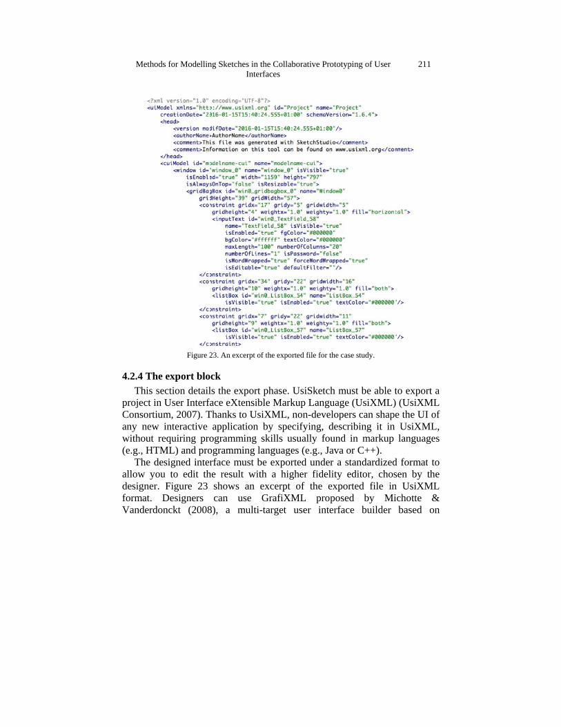
export bloection detailUser Interfm, 2007). Tinteractive equiring proML) and proesigned inteu to edit thFigure 23
Designers nckt (2008
ng Sketches inInt
23. An excerpt
ock ls the exporface eXtensiThanks to U
applicationogrammingogramming rface must
he result wshows an can use
8), a mult
n the Collaborerfaces
of the exported
rt phase. Usible Markup
UsiXML, non by specifg skills usua
languages (be exportedith a higheexcerpt ofGrafiXML
ti-target us
rative Prototyp
d file for the cas
siSketch mup Languagen-developer
fying, descrally found (e.g., Java od under a ser fidelity ef the exporL proposeser interfac
ping of User
se study.
ust be able te (UsiXML)rs can shapribing it in in markup
or C++). tandardizededitor, chosrted file ind by Mi
ce builder
211
to export a ) (UsiXML e the UI of UsiXML, languages
d format to sen by the n UsiXML ichotte & based on
212
UsiXML f
4.3 The EThis s
UsiSketchuser interfhas the flefinal userscreens, rocould enabto improveinterface winclude fin
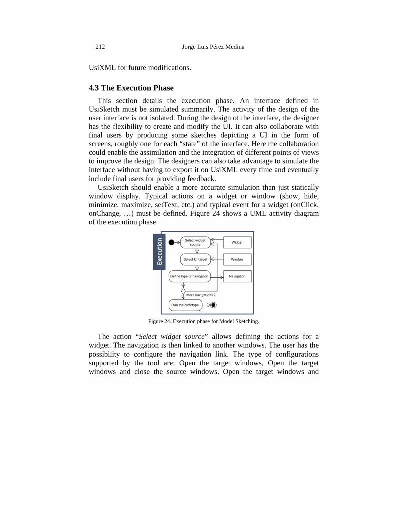
UsiSkewindow dminimize,onChangeof the exe
The acwidget. Thpossibilitysupported windows
for future m
Execution section detah must be sface is not iexibility to rs by produoughly one ble the assime the designwithout havnal users foretch should display. Ty, maximize,e, …) must cution phas
Fi
ction “Seleche navigatioy to config
by the toand close
Jo
modification
Phase ails the eximulated susolated. Ducreate and
ucing somefor each “smilation andn. The desigving to expor providing enable a m
ypical actio, setText, etbe defined
se.
igure 24. Execu
ct widget son is then l
gure the naool are: Op
the source
orge Luis Pére
ns.
xecution pummarily. Turing the des
modify thee sketches tate” of the d the integr
gners can alort it on Usifeedback.
more accuraons on a wtc.) and typ. Figure 24
ution phase for
source” allinked to an
avigation lipen the tare windows,
ez Medina
hase. An The activitysign of the ie UI. It can depicting ainterface. H
ration of difso take adviXML every
ate simulatiowidget or wical event f
4 shows a U
Model Sketchin
ows defininother windonk. The tyrget windo
Open the
interface dy of the desinterface, thalso collab
a UI in thHere the colfferent pointvantage to siy time and
on than juswindow (shfor a widgetUML activit
ng.
ng the actiows. The u
ype of confows, Open
target win
defined in sign of the he designer borate with he form of llaboration ts of views imulate the eventually
st statically how, hide, t (onClick, ty diagram
ions for a ser has the figurations the target
ndows and
Methods for Modelling Sketches in the Collaborative Prototyping of User Interfaces
213
maximize or minimize the source windows, Open the target windows in front of (or in back of) the source windows. Finally, the user can execute the prototype.
5. Conclusion We have presented a sketching recognition method used to develop
UsiSketch. Its technology runs on cross-platform and supports sketching recognition on different surfaces based.
The presented method describes a new recognition algorithm that accommodates very large surfaces. It has the ability to recognize shapes and combinations of shapes. Actually, UsiSketch recognizes and interprets 8 basic predefined shapes (i.e., triangle, rectangle, line, cross, wavy line, arrow, ellipse, and circle); 32 different types of widgets (ranging from check boxes, listboxs, textfields, buttons, video multimedia, etc.), and 6 basic commands (i.e., undo, redo, copy, paste, cut, new window).
Users of different domains can combine multiple simple shapes in a more complex combination or widget, according to pre-established rules. The recognition is done at the time of drawing, and not at the end thereof. The high fidelity elements are widgets. These are very numerous, and new ones appear frequently. Therefore, and since the recognition algorithms are based on a supervised learning, wanting to recognize these individual widgets requires a training phase of the tool for each of them. Such a process would be tedious, and will never be completed: for every new widget, we should repeat the process.
We have addressed the solution using the representation of a low fidelity widget as a composition of simple geometric shapes. For this reason, we decided to implement pattern recognition only on these geometric forms, greatly reducing the number of shapes to recognize. This reduces the time needed to train the algorithm. These forms are then combined in predefined grammars.
Currently, we are working on developing new features. We will be able to easily evaluate the feasibility of our tool by conducting user experiments. The results will be used to evaluate the performance of the tool, and obtain new research perspectives.
214 Jorge Luis Pérez Medina
Acknowledgement The authors would like to thank Olivier Bourdoux for the big contribution to the UsiSketch tool.
References Bastéa-Forte, M., & Yen, C. (2007). Encouraging contribution to shared sketches in
brainstorming meetings. In CHI ’07 Extended Abstracts on Human Factors in Computing Systems CHI EA’07 (pp. 2267–2272). New York, NY, USA: ACM.
Beirekdar, A., Vanderdonckt, J., & Noirhomme-Fraiture, M. (2002). A Framework and a Language for Usability Automatic Evaluation of Web Sites by Static Analysis of HTML Source Code. In Proc. of CADUI’2002, pp. 337-348, Kluwer Academics Pub.
Beuvens, F., & Vanderdonckt, J. (2012). UsiGesture: An environment for integrating pen-based interaction in user interface development. In Proceedings of Sixth International Conference on Research Challenges in Information Science RCIS’2012 (pp. 1–12).
Buxton, B. (2007). Sketching User Experiences: Getting the Design Right and the Right Design. San Francisco, CA, USA: Morgan Kaufmann Publishers Inc.
Caetano, A., Goulart, N., Fonseca, M., Jorge, J. (2002) JavaSketchIt: Issues in Sketching the Look of User Interfaces. In Proceedings of the 2002 AAAI Spring Symposium - Sketch Understanding (Palo Alto, March 2002). AAAI Press (2002) 9–14.
Cherubini, M., Venolia, G., DeLine, R., & Ko, A. J. (2007). Let’s go to the whiteboard: How and why software developers use drawings. In Proc. SIGCHI Conference on Human Factors in Computing Systems CHI’2007 (pp. 557–566), ACM.
Coutaz, J. (2010). User interface plasticity: Model driven engineering to the limit! In Proc. of the 2Nd ACM SIGCHI Symposium on Engineering Interactive Computing Systems EICS’2010 (pp. 1–8). New York,: ACM. doi:10.1145/1822018.1822019.
Coyette, A., Faulkner, S., Kolp, M., Limbourg, Q., & Vanderdonckt, J. (2004). Sketchixml: Towards a multi-agent design tool for sketching user interfaces based on usixml. In Proceedings of TAMODIA’2004 (pp. 75–82), ACM.
Coyette, A., Schimke, S., Vanderdonckt, J., & Vielhauer, C. (2007). Trainable sketch recognizer for graphical user interface design. In C. Baranauskas, P. Palanque, J. Abascal, & S. Barbosa (Eds.), Proc. of INTERACT 2007 (pp. 124–135). Springer.
D. Llorens, et al. (2008). The UjiPenchars database: a pen-based database of isolated handwritten characters. In Proceedings of the Sixth International Conference on Language Resources and Evaluation LREC’2008. Marrakech, Morocco. Http://www.lrec-conf.org/proceedings/lrec2008/.
David, J., Eoff, B., and Hammond, T. (2010). CoSke-An Exploration in Collaborative Sketching. In Proceedings of the ACM conference on Computer supported cooperative work CSCW’2010, (pp. 471–472). New York, NY, USA: ACM.
Methods for Modelling Sketches in the Collaborative Prototyping of User Interfaces
215
Demeure, A., Masson, D., & Calvary, G. (2011). Graphs of Models for Exploring Design Spaces in the engineering of Human Computer Interaction. In Proc. of ACM IUI’2011 (p. 5p.). Palo Alto, CA, United States.
Eisenstein, J., Vanderdonckt, J., & Puerta, A. (2001). Model-Based User-Interface Development Techniques for Mobile Computing. In Proc. of 5th ACM Int. Conf. on Intelligent User Interfaces IUI’2001 (pp. 69–76) , ACM.
Florins, M., Montero, F., Vanderdonckt, J., & Michotte, B. (2006). Splitting Rules for Graceful Degradation of User Interfaces. In Proc. of 8th Int. Working Conference on Advanced Visual Interfaces AVI’2006 (Venezia, 23-26 May 2006) (pp. 59–66). New York, NY, USA: ACM Press.
Geyer, F., Jetter, H.-C., Pfeil, U., & Reiterer, H. (2010). Collaborative sketching with distributed displays and multimodal interfaces. In Proceedings of ACM International Conference on Interactive Tabletops and Surfaces ITS’2010 (pp. 259– 260). New York, NY, USA: ACM. doi:10.1145/1936652.1936705.
Goel, V. (1995). Sketches of Thought. Cambridge, MA: MIT Press. Gonzalez-Pérez, C. (2010). Filling the voids - from requirements to deployment with
open/metis. In ICSOFT 2010 - Proceedings of the Fifth International Conference on Software and Data Technologies, Volume 1, Athens, Greece, July 22-24, 2010 (p. 19).
Hailpern, J., Hinterbichler, E., Leppert, C., Cook, D., & Bailey, B. P. (2007). Team storm: Demonstrating an interaction model for working with mul- tiple ideas during creative group work. In Proceedings of the 6th ACM SIGCHI Conference on Creativity &Amp; Cognition C&C’2007 (pp. 193–202). New York, NY, USA: ACM.
Haller, M., Leitner, J., Seifried, T., Wallace, J. R., Scott, S. D., Richter, C., Brandl, P., Gokcezade, A., & Hunter, S. (2010). The nice discussion room: Integrating paper and digital media to support co-located group meetings. In Proceedings of the ACM Conference on Human Factors in Computing Systems CHI’2010 (pp. 609–618), ACM.
Haralick, R. M., & Elliott, G. L. (1979). Increasing tree search efficiency for constraint satisfaction problems. In Proceedings of the 6th International Joint Conference on Artificial Intelligence - Volume 1 IJCAI’1979 (pp. 356–364). San Francisco, CA, USA: Morgan Kaufmann Publishers Inc.
Johnson, G., Gross, M. D., Hong, J., & Yi-Luen Do, E. (2009). Computational support for sketching in design: a review. Foundations and Trends in Human-Computer Interaction, 2, 1–93.
Kent, S. (2002). Model driven engineering. In M. Butler, L. Petre, & K. Sere (Eds.), Integrated Formal Methods (pp. 286–298). Springer Berlin Heidelberg volume 2335 of Lecture Notes in Computer Science. doi:10.1007/3-540-47884-1_16.
van der Lugt, R. (2002). Functions of sketching in design idea generation meetings. In Proceedings of the 4th Conference on Creativity & Cognition C&C’2002 (pp. 72–79). New York, NY, USA: ACM.
Mangano, N., Baker, A., Dempsey, M., Navarro, E., & van der Hoek, A. (2010). Software
216 Jorge Luis Pérez Medina
design sketching with calico. In Proceedings of the IEEE/ACM International Conference on Automated Software Engineering ASE’2010 (pp. 23–32). New York, NY, USA: ACM.
Meserve, B. E. (1983). Fundamental concepts of geometry. Courier Corporation. Michotte, B., & Vanderdonckt, J. (2008). GrafiXML, a multi-target user interface builder
based on usixml. In Proceedings of Fourth International Conference on Autonomic and Autonomous Systems ICAS’2008 (pp. 15–22). Piscataway, USA: IEEE Press. doi:10.1109/ICAS. 2008.29.
Oncina, J., & Sebban, M. (2006). Learning stochastic edit distance: Application in handwritten character recognition. Pattern Recognition, 39 , 1575–1587. doi:http://dx.doi.org/ 10.1016/j.patcog.2006.03.011.
Pérez-Medina, J.-L., Dupuy-Chessa, S., & Front, A. (2007). A survey of model driven engineering tools for user interface design. In M. Winckler, H. Johnson, & P. Palanque (Eds.), Task Models and Diagrams for User Interface Design (pp. 84–97). Springer Berlin Heidelberg volume 4849 of Lecture Notes in Computer Science. doi:10.1007/978-3-540-77222-4_8.
Rubine, D. (1991). Specifying gestures by example. In Proceedings of the 18th Annual Conference on Computer Graphics and Interactive Techniques SIGGRAPH ’91 (pp. 329–337). New York, NY, USA: ACM..
Schon, D. A., & Wiggins, G. (1992). Kinds of seeing and their functions in designing. Design Studies, 13 , 135 – 156. doi:http: //dx.doi.org/10.1016/0142-694X(92)90 268-F.
Sharp, Y., H. Rogers, & Preece, J. (2007). Interaction Design: Beyond HCI. New York, USA: John Wiley and Sons.
UsiXML Consortium. UsiXML, a General Purpose XML Compliant user Interface Description Language, UsiXML V1.8, 23 February 2007. Available on line: http://www.usixml.org.
Vatavu, R.-D., Anthony, L., & Wobbrock, J. O. (2012). Gestures as point clouds: A $p recognizer for user interface prototypes. In Proceedings of the 14th ACM International Conference on Multimodal Interaction ICMI ’12 (pp. 273–280), ACM.
Wobbrock, J. O., Wilson, A. D., & Li, Y. (2007). Gestures without libraries, toolkits or training: A $1 recognizer for user interface proto- types. In Proceedings of the 20th Annual ACM Symposium on User Interface Software and Technology UIST’2007 (pp. 159–168). New York, NY, USA: ACM. doi:10.1145/1294211.1294238.
Wuest, D., Seyff, N., & Glinz, M. (2015a). Flexisketch team: Collaborative sketching and notation creation on the fly. In IEEE/ACM 37th IEEE International Conference on Software Engineering ICS’2015 (pp. 685–688). volume 2.
Wuest, D., Seyff, N., & Glinz, M. (2015b). Sketching and notation creation with flexisketch team: Evaluating a new means for collaborative requirements elicitation. In Proceedings of IEEE 23rd International Conference on Requirements Engineering RE’2015 (pp. 186–195).