Embed Size (px)
Citation preview

231
Methods for Optimized On-Line Cleaning
Was
te In
cine
rati
on
Methods for Optimized On-Line Cleaning
Franziska Graube, Sebastian Grahl, Matthias Reiche and Michael Beckmann
1. Deposit situation in waste incinerators ....................................................232
2. Cleaning situation in waste incinerators ..................................................233
2.1. Necessity of cleaning and appropriate cleaning adjustment..................233
2.2 On-line cleaning systems ...........................................................................233
2.3. Identified cleaning mechanisms ................................................................235
3. Strategy for comprehensive cleaning optimization ................................236
3.1. Synergy of fuel, operational mode and plant efficiency .........................236
3.2. Online balancing tool to optimize the process control ..........................239
3.3. Measurement systems for evaluation of deposit .....................................2393.3.1. Heat flux sensor ...........................................................................................2393.3.2. Laser thickness sensor ................................................................................2393.3.3. Deposit sensor .............................................................................................240
3.4. Mathematical model ...................................................................................242
3.5. Necessity of measurement systems, on-line balancing and mathematical models exemplary for the incinerator MHKW Coburg ..........................................................................................242
4. Conclusion ...................................................................................................243
5. References ....................................................................................................243
The combustion of waste releases compounds which form deposits on the walls. These deposits might either lead to slagging or fouling. Fouling occurs both in the convective part and in the radiative part of the steam generator while slagging can be found mainly in the radiation section. [17]
Deposits need to be avoided for two main reasons – first of all they limit the heat output [8] and second, they may react corrosively. This leads to damages of the incinerator’s water tube walls [10]. To avoid these deposits, the operators have two possibilities. Either they influence the process control in such a way that less deposits are created (primary measures) or they remove the deposits due to cleaning methods (secondary measures). As both possibilities are not necessarily sufficient, real incinerators need an overall concept that includes primary and secondary measures to maintain high efficiency and long lift-time [4]. The following paper presents a comprehensive method
Franziska Graube, Sebastian Grahl, Matthias Reiche, Michael Beckmann
232
Was
te In
cine
rati
on
that integrates both primary and secondary measures. The primary measures focus on the process control and how to predict the deposit growth. Nonetheless, the focus lies on the secondary measures, especially the cleaning with water, and potential adjustable parameters to improve the current standard.
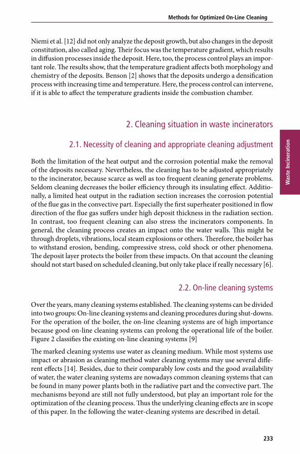
1. Deposit situation in waste incineratorsThe fouling and slagging on the walls depend on several parameters such as waste composition, heat input, mass flow of flue gas and air flow along the walls and others. Summarized, fouling and slagging are strongly linked to process parameters. Waste in particular exhibits different waste compositions [16] and temporal changes which lead to variation of the compounds and fluctuation of the heat input respectively.
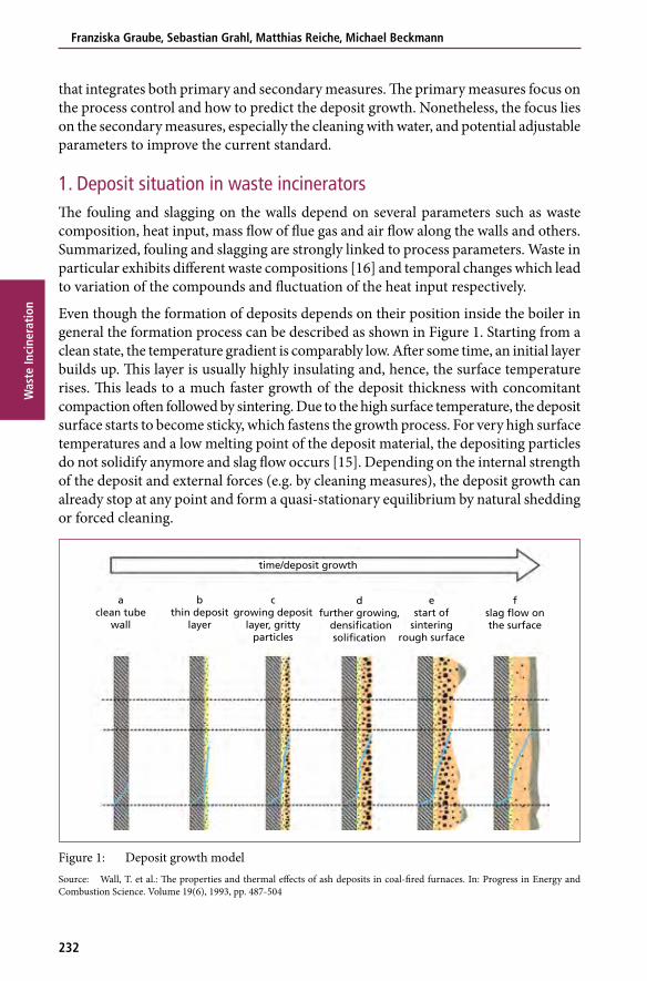
Even though the formation of deposits depends on their position inside the boiler in general the formation process can be described as shown in Figure 1. Starting from a clean state, the temperature gradient is comparably low. After some time, an initial layer builds up. This layer is usually highly insulating and, hence, the surface temperature rises. This leads to a much faster growth of the deposit thickness with concomitant compaction often followed by sintering. Due to the high surface temperature, the deposit surface starts to become sticky, which fastens the growth process. For very high surface temperatures and a low melting point of the deposit material, the depositing particles do not solidify anymore and slag flow occurs [15]. Depending on the internal strength of the deposit and external forces (e.g. by cleaning measures), the deposit growth can already stop at any point and form a quasi-stationary equilibrium by natural shedding or forced cleaning.
Figure 1: Deposit growth modelSource: Wall, T. et al.: The properties and thermal effects of ash deposits in coal-fired furnaces. In: Progress in Energy and Combustion Science. Volume 19(6), 1993, pp. 487-504
time/deposit growth
aclean tube
wall
bthin deposit
layer
fslag flow onthe surface
cgrowing deposit
layer, grittyparticles
dfurther growing,
densificationsolification
estart of
sinteringrough surface
233
Methods for Optimized On-Line Cleaning
Was
te In
cine
rati
on
Niemi et al. [12] did not only analyze the deposit growth, but also changes in the deposit constitution, also called aging. Their focus was the temperature gradient, which results in diffusion processes inside the deposit. Here, too, the process control plays an impor-tant role. The results show, that the temperature gradient affects both morphology and chemistry of the deposits. Benson [2] shows that the deposits undergo a densification process with increasing time and temperature. Here, the process control can intervene, if it is able to affect the temperature gradients inside the combustion chamber.
2. Cleaning situation in waste incinerators
2.1. Necessity of cleaning and appropriate cleaning adjustment
Both the limitation of the heat output and the corrosion potential make the removal of the deposits necessary. Nevertheless, the cleaning has to be adjusted appropriately to the incinerator, because scarce as well as too frequent cleaning generate problems. Seldom cleaning decreases the boiler efficiency through its insulating effect. Additio-nally, a limited heat output in the radiation section increases the corrosion potential of the flue gas in the convective part. Especially the first superheater positioned in flow direction of the flue gas suffers under high deposit thickness in the radiation section. In contrast, too frequent cleaning can also stress the incinerators components. In general, the cleaning process creates an impact onto the water walls. This might be through droplets, vibrations, local steam explosions or others. Therefore, the boiler has to withstand erosion, bending, compressive stress, cold shock or other phenomena. The deposit layer protects the boiler from these impacts. On that account the cleaning should not start based on scheduled cleaning, but only take place if really necessary [6].
2.2. On-line cleaning systems
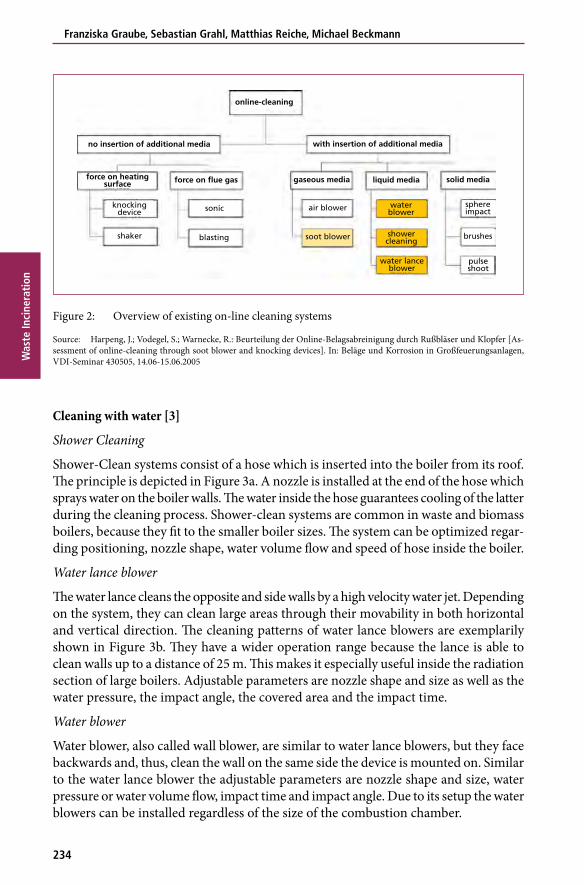
Over the years, many cleaning systems established. The cleaning systems can be divided into two groups: On-line cleaning systems and cleaning procedures during shut-downs. For the operation of the boiler, the on-line cleaning systems are of high importance because good on-line cleaning systems can prolong the operational life of the boiler. Figure 2 classifies the existing on-line cleaning systems [9]
The marked cleaning systems use water as cleaning medium. While most systems use impact or abrasion as cleaning method water cleaning systems may use several diffe-rent effects [14]. Besides, due to their comparably low costs and the good availability of water, the water cleaning systems are nowadays common cleaning systems that can be found in many power plants both in the radiative part and the convective part. The mechanisms beyond are still not fully understood, but play an important role for the optimization of the cleaning process. Thus the underlying cleaning effects are in scope of this paper. In the following the water-cleaning systems are described in detail.
Franziska Graube, Sebastian Grahl, Matthias Reiche, Michael Beckmann
234
Was
te In
cine
rati
on
Cleaning with water [3]
Shower Cleaning
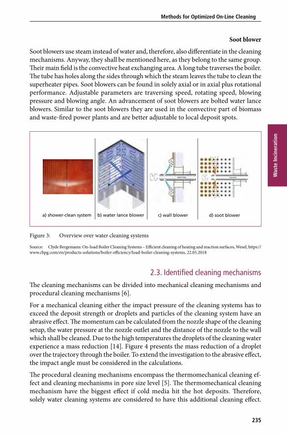
Shower-Clean systems consist of a hose which is inserted into the boiler from its roof. The principle is depicted in Figure 3a. A nozzle is installed at the end of the hose which sprays water on the boiler walls. The water inside the hose guarantees cooling of the latter during the cleaning process. Shower-clean systems are common in waste and biomass boilers, because they fit to the smaller boiler sizes. The system can be optimized regar-ding positioning, nozzle shape, water volume flow and speed of hose inside the boiler.
Water lance blower
The water lance cleans the opposite and side walls by a high velocity water jet. Depending on the system, they can clean large areas through their movability in both horizontal and vertical direction. The cleaning patterns of water lance blowers are exemplarily shown in Figure 3b. They have a wider operation range because the lance is able to clean walls up to a distance of 25 m. This makes it especially useful inside the radiation section of large boilers. Adjustable parameters are nozzle shape and size as well as the water pressure, the impact angle, the covered area and the impact time.
Water blower
Water blower, also called wall blower, are similar to water lance blowers, but they face backwards and, thus, clean the wall on the same side the device is mounted on. Similar to the water lance blower the adjustable parameters are nozzle shape and size, water pressure or water volume flow, impact time and impact angle. Due to its setup the water blowers can be installed regardless of the size of the combustion chamber.
Figure 2: Overview of existing on-line cleaning systems
Source: Harpeng, J.; Vodegel, S.; Warnecke, R.: Beurteilung der Online-Belagsabreinigung durch Rußbläser und Klopfer [As-sessment of online-cleaning through soot blower and knocking devices]. In: Beläge und Korrosion in Großfeuerungsanlagen, VDI-Seminar 430505, 14.06-15.06.2005
solid medialiquid mediagaseous media
with insertion of additional mediano insertion of additional media
online-cleaning
force on flue gasforce on heatingsurface
knockingdevice sonic air blower
blasting soot blower
sphereimpact
pulseshoot
brushesshowercleaning
water lanceblower
waterblower
shaker
235
Methods for Optimized On-Line Cleaning
Was
te In
cine
rati
on
Soot blower
Soot blowers use steam instead of water and, therefore, also differentiate in the cleaning mechanisms. Anyway, they shall be mentioned here, as they belong to the same group. Their main field is the convective heat exchanging area. A long tube traverses the boiler. The tube has holes along the sides through which the steam leaves the tube to clean the superheater pipes. Soot blowers can be found in solely axial or in axial plus rotational performance. Adjustable parameters are traversing speed, rotating speed, blowing pressure and blowing angle. An advancement of soot blowers are bolted water lance blowers. Similar to the soot blowers they are used in the convective part of biomass and waste-fired power plants and are better adjustable to local deposit spots.
Figure 3: Overview over water cleaning systems
Source: Clyde Bergemann: On-load Boiler Cleaning Systems – Efficient cleaning of heating and reaction surfaces, Wesel, https://www.cbpg.com/en/products-solutions/boiler-efficiency/load-boiler-cleaning-systems, 22.05.2018
2.3. Identified cleaning mechanismsThe cleaning mechanisms can be divided into mechanical cleaning mechanisms and procedural cleaning mechanisms [6].
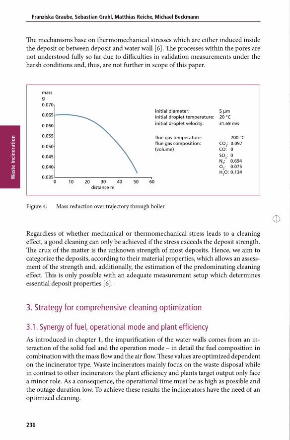
For a mechanical cleaning either the impact pressure of the cleaning systems has to exceed the deposit strength or droplets and particles of the cleaning system have an abrasive effect. The momentum can be calculated from the nozzle shape of the cleaning setup, the water pressure at the nozzle outlet and the distance of the nozzle to the wall which shall be cleaned. Due to the high temperatures the droplets of the cleaning water experience a mass reduction [14]. Figure 4 presents the mass reduction of a droplet over the trajectory through the boiler. To extend the investigation to the abrasive effect, the impact angle must be considered in the calculations.
The procedural cleaning mechanisms encompass the thermomechanical cleaning ef-fect and cleaning mechanisms in pore size level [5]. The thermomechanical cleaning mechanism have the biggest effect if cold media hit the hot deposits. Therefore, solely water cleaning systems are considered to have this additional cleaning effect.
a) shower-clean system b) water lance blower d) soot blowerc) wall blower
Franziska Graube, Sebastian Grahl, Matthias Reiche, Michael Beckmann
236
Was
te In
cine
rati
on
The mechanisms base on thermomechanical stresses which are either induced inside the deposit or between deposit and water wall [6]. The processes within the pores are not understood fully so far due to difficulties in validation measurements under the harsh conditions and, thus, are not further in scope of this paper.
Figure 4: Mass reduction over trajectory through boiler
Regardless of whether mechanical or thermomechanical stress leads to a cleaning effect, a good cleaning can only be achieved if the stress exceeds the deposit strength. The crux of the matter is the unknown strength of most deposits. Hence, we aim to categorize the deposits, according to their material properties, which allows an assess-ment of the strength and, additionally, the estimation of the predominating cleaning effect. This is only possible with an adequate measurement setup which determines essential deposit properties [6].
3. Strategy for comprehensive cleaning optimization
3.1. Synergy of fuel, operational mode and plant efficiency As introduced in chapter 1, the impurification of the water walls comes from an in-teraction of the solid fuel and the operation mode – in detail the fuel composition in combination with the mass flow and the air flow. These values are optimized dependent on the incinerator type. Waste incinerators mainly focus on the waste disposal while in contrast to other incinerators the plant efficiency and plants target output only face a minor role. As a consequence, the operational time must be as high as possible and the outage duration low. To achieve these results the incinerators have the need of an optimized cleaning.
0.070
massg
initial diameter: 5 µminitial droplet temperature: 20 °Cinitial droplet velocity: 31.69 m/s
flue gas temperature: 700 °Cflue gas composition: CO2: 0.097(volume) CO: 0
SO2: 0N2: 0.694O2: 0.075H2O: 0.134
0.065
0.055
0.050
0.045
0.040
0.03510
distance m20 30 40 50 600
0.060
Taking the leadis our duty.
As Germany’s leading company for the production of power and heat from thermal waste treatment we consider it our duty to take the lead. With ultra-modern waste incineration plants which are state-of-the-art in terms of both technology and ecology, with impressive services and binding values which inform our thinking and actions. We are driven on by constant change. With an eye on the legal framework conditions and the demands of the future, we develop sustainable and future- based solutions on which we are proud to be judged. www.eew-energyfromwaste.com
Anzeige IRRC 2018_v02.indd 1 2018-09-11 16:22
We Are Closing the Cycle:Your Expert Partner for Thermal and Biological Energy-from-Waste Plants
Our solutions are based on e� cient and environmentally sound in-house technology, and cover the
entire life cycle of an Energy-from-Waste facility. Our proven technologies have been part of more
than 700 plants worldwide. As a global leader in energy from waste we are proud to be able to say:
We deliver. Check our references.
Waste is our Energy www.hz-inova.com
239
Methods for Optimized On-Line Cleaning
Was
te In
cine
rati
on
More precisely, both the undisturbed operation of the boiler and the throughput are the overall goals of the boiler. This is why they need a tool to forecast the effects of process parameters on both the cleanliness of the boiler and the boiler efficiency. Therefore, the following chapter presents an approach to improve the process control [1].
3.2. Online balancing tool to optimize the process controlOperators face the problem that the deposit location is hard to predict during the operation and the operational staff has little range to optimize the overall process. Thus, online balancing programs were designed, which (online balancing program Beckmann) list detailed descriptions of energy and mass flows in the incinerator and, furthermore, help the operator to manually affect the process control. The overall aim of such an online balancing program is the increase of the plant efficiency, the subordi-nated aim is the detection of local spots that need improvement or regulations through process parameters (e.g. air flow). Problematically, the online balancing tool only is able to estimate the values at the system boundaries which cannot be measured directly. Whereas, the values in between are in a black box. For example the deposit thickness inside one system is assumed to have everywhere the same thickness or properties. To maintain more precise results several sensors have to be included that deliver signals for the balancing sub-areas. Following, several sensors are described that improve the data acquisition with focus on deposit detection and characterization [1]. All these sensors were developed to gain more knowledge about the deposit situation inside the boiler and may help as columns for the online balancing tool.
3.3. Measurement systems for evaluation of depositAt the TU Dresden several sensors were developed which aim to analyze deposits during operation as detailed as possible. Thus, the following chapter only gives an overview over internal measurement technologies and does not try to outline all available solu-tions. These internal methods shall be used afterwards for our mathematical models.
3.3.1. Heat flux sensor
On the market exist a couple of heat flux sensors. The heat flux sensor used at our chair consists of a pair of thermocouples which are installed at the outside of the water wall. The thermocouples are installed on the bridge and the tube crown, so that the signal delivers the heat flux to the water wall. Deposits on the inner side immediately influence the heat flux signal through their damping properties. Therefore, the heat flux sensor is suitable for tracking deposits. More details about the specific heat flux sensor can be found in the dissertation of Krüger [11].
3.3.2. Laser thickness sensor
The damping of the signal alone does not deliver detailed information about the de-posits. An assessment of the deposit either consisting of a thin highly isolating layer or thick conductive layer is not possible. For determination of the deposit’s thickness the
Franziska Graube, Sebastian Grahl, Matthias Reiche, Michael Beckmann
240
Was
te In
cine
rati
on
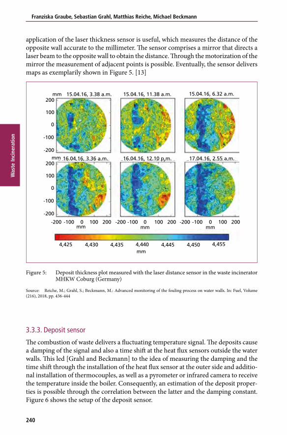
application of the laser thickness sensor is useful, which measures the distance of the opposite wall accurate to the millimeter. The sensor comprises a mirror that directs a laser beam to the opposite wall to obtain the distance. Through the motorization of the mirror the measurement of adjacent points is possible. Eventually, the sensor delivers maps as exemplarily shown in Figure 5. [13]
Figure 5: Deposit thickness plot measured with the laser distance sensor in the waste incinerator MHKW Coburg (Germany)
Source: Reiche, M.; Grahl, S.; Beckmann, M.: Advanced monitoring of the fouling process on water walls. In: Fuel, Volume (216), 2018, pp. 436-444
3.3.3. Deposit sensor
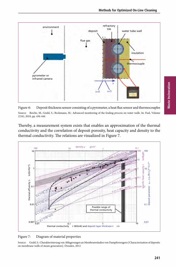
The combustion of waste delivers a fluctuating temperature signal. The deposits cause a damping of the signal and also a time shift at the heat flux sensors outside the water walls. This led [Grahl and Beckmann] to the idea of measuring the damping and the time shift through the installation of the heat flux sensor at the outer side and additio-nal installation of thermocouples, as well as a pyrometer or infrared camera to receive the temperature inside the boiler. Consequently, an estimation of the deposit proper-ties is possible through the correlation between the latter and the damping constant. Figure 6 shows the setup of the deposit sensor.
200
100
-200
-100
0
200
100
-200
-100
0
mm
mm
15.04.16, 3.38 a.m. 15.04.16, 11.38 a.m. 15.04.16, 6.32 a.m.
16.04.16, 3.36 a.m. 16.04.16, 12.10 p.m. 17.04.16, 2.55 a.m.
200100-200 -100 0 200100-200 -100 0 200100-200 -100 0mm mm mm
mm4,425 4,430 4,435 4,440 4,445 4,450 4,455
241
Methods for Optimized On-Line Cleaning
Was
te In
cine
rati
on
Figure 6: Deposit thickness sensor consisting of a pyrometer, a heat flux sensor and thermocouples Source: Reiche, M.; Grahl, S.; Beckmann, M.: Advanced monitoring of the fouling process on water walls. In: Fuel, Volume (216), 2018, pp. 436-444
Thereby, a measurement system exists that enables an approximation of the thermal conductivity and the correlation of deposit porosity, heat capacity and density to the thermal conductivity. The relations are visualized in Figure 7.
Figure 7: Diagram of material propertiesSource: Grahl, S.: Charakterisierung von Ablagerungen an Membranwänden von Dampferzeugern [Characterization of deposits on membrane walls of steam generators]. Dresden, 2012
environment
pyrometer orinfrared camera
flue gas
deposit
refractorytile
water tube wall
insulation
thermocouple
x=0 x=5
x
10100 10 1
density ρ g/cm3
1
10
0.1
0.01
ther
mal
eff
usi
vity
b
kJ
/(m
2 Ks0.
5 )
0.0010.01 1010.1
thermal conductivity λ W/(mK) and deposit layer thickness δ cm
0.1100
10
1
0.1
0.01 spec
ific
hea
t ca
pac
ity
c
kJ/
(kg
K)
0.1
0.01
10
1
100
Possible range ofthermal conductivity
a = 1•10-4 m2 /sa = 1•10-5 m
2 /sa = 1•10-6 m
2 /sa = 1•10-7 m
2 /sρ
ρ
•c= 1•100kJ/(m3K)
•c= 1•101kJ/(m3K)
ρ
ρ
•c= 1•102kJ/(m3K)
•c= 1•103kJ/(m3K)
ρ •c= 1•104kJ/(m3K)
dep
osi
t p
aram
eter
Δ
ϖ =
t•
(4π/
τ 0)0.
5 in
s0.
5
Franziska Graube, Sebastian Grahl, Matthias Reiche, Michael Beckmann
242
Was
te In
cine
rati
on
The combination with the laser thickness sensor delivers an even more precise result. Thus, the deposit thickness and the deposit properties are available for further impro-vements of the cleaning process. [13]
3.4. Mathematical modelThe combination of the deposit sensor and the laser thickness sensor results in relatively accurate description of the deposit. These data can be fed into mathematical models to predict the cleaning efficiency. The principle mechanisms described in chapter 2.3. are incorporated into these mathematical models, which calculate the actually arising stresses during the cleaning process.
3.5. Necessity of measurement systems, on-line balancing and mathematical models exemplary for the incinerator MHKW Coburg
At the incinerator in Coburg all the presented programs and sensors were deployed and the cleaning was evaluated with a mathematical program. The online balancing program delivered overall data of the incinerator. The laser thickness sensor and the
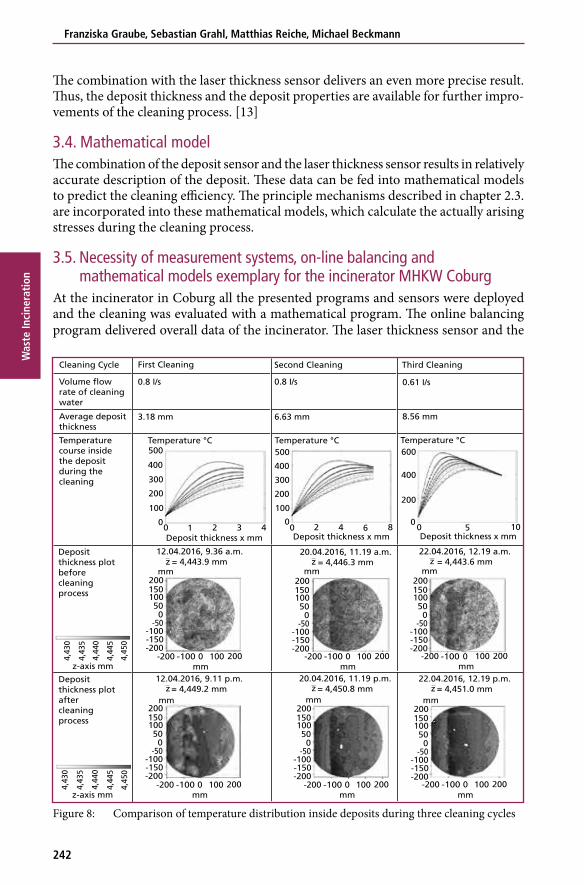
Figure 8: Comparison of temperature distribution inside deposits during three cleaning cycles
500
400
300
200
200
200
150
500
0
100
100-200
-200
-50
200150
500
100
-200-150
-50-100
-100
100
0
500
400
600
400
200
0
300
200
100
00 1 2 3 4 0 2 4 6 8 0 105
Temperature °CTemperaturecourse insidethe depositduring thecleaning
Depositthickness plotbeforecleaningprocess
Depositthickness plotaftercleaningprocess
First Cleaning
0.8 I/s
3.18 mm 6.63 mm 8.56 mm
0.8 I/s 0.61 I/s
Cleaning Cycle
Volume flowrate of cleaningwater
Average depositthickness
Second Cleaning Third Cleaning
Temperature °C Temperature °C
Deposit thickness x mm
mmz-axis mm2000 100-200 -100
mm
12.04.2016, 9.36 a.m.= 4,443.9 mm
20.04.2016, 11.19 a.m.= 4,446.3 mm
22.04.2016, 12.19 a.m.= 4,443.6 mm
mm200150
500
100
-200-150
-50-100
mm
200150
500
100
-200-150
-50-100
mmmm200150
500
100
-200-150
-50-100
mm
2000 100-200 -100mm
200150
500
100
-200-150
-50-100
mm
Deposit thickness x mm Deposit thickness x mm
z z z
12.04.2016, 9.11 p.m.= 4,449.2 mm
20.04.2016, 11.19 p.m.= 4,450.8 mm
22.04.2016, 12.19 p.m.= 4,451.0 mmzz z
2000 100-200
4,43
0
4,43
5
4,44
0
4,44
5
4,45
0
z-axis mm
4,43
0
4,43
5
4,44
0
4,44
5
4,45
0
-100mm
2000 100-200 -100mm
2000 100-200 -100mm
-100-150
243
Methods for Optimized On-Line Cleaning
Was
te In
cine
rati
on
deposit sensor measured the properties of the deposit. Three cleaning procedures were analyzed regarding the setup [13]. All three cleaning procedures were successful. Nevertheless, the last cleaning used less water than the first cleaning sequences. This was very useful, because a calculation of the thermomechanical stress and the temperature distribution showed that the use of too much water cooled down the whole deposits and the water tube wall. Risk of tube damage rises if the water tube wall is cooled down so that thermomechanical stress is induced. Table 1 shows the temperature distribu-tion during the cleaning process for all three cleaning cycles. The highest curve is the temperature course immediately after the beginning of the cleaning while the lowest curve shows the temperature course 1 second after the start. Below the temperature courses are deposit thickness plots that show the success of all three cleaning cycles. Even though less water was used for the last cycle and the deposit thickness was higher, the cleaning achieved comparably good results.
This example shows that with knowledge of deposit thickness and thermal conducti-vity a stress reduction of the water tube wall is possible. To help the operational staff evaluating these results the balancing tool may include a visualization of the deposit level, which facilitates the evaluation. Furthermore, an analyzation of previous cleaning cycles and deposit development can help to predict the future impurification level.
4. ConclusionThe cleaning with water is a widely established possibility to remove deposits from the water tube walls of waste incinerators. Nonetheless, the application is often not need-based but follows scheduled operating plans.
The current paper presented a concept that included both an interference with the process control and the use of sensor systems combined with mathematical calculations to maintain an efficient cleaning and long life cycles of the power plant simultaneously. The process control was optimized with aid of the online balancing program. The pro-gram was combined with the laser thickness sensor and the deposit sensor. The sensors delivered data for a calculation program that contrasts the deposit properties from the sensors with the cleaning setup from the process control to assess the cleaning effici-ency. Exemplarily, the procedure is sketched out for the waste incinerator in Coburg. Three cleaning cycles were evaluated and an improvement of the cleaning with aid of the measurement technique could be achieved.
5. References[1] Beckmann, M. et al.: Possibilities of Process Optimization in Municipal Solid Waste Incineration
Plants by an Online Balancing Program. In: Proceedings of the International Conference on Incineration and Thermal Treatment Technologies – IT3, Galveston (USA), 09.05.-13.05.2005
[2] Benson, S.: Impact of Coal Blending on Boiler Slag and Bottom Ash Characteristics In: Coal Combustion Residuals Conference, Dallas (USA), 20.07.-22.07.2014
[3] Clyde Bergemann: On-load Boiler Cleaning Systems – Efficient cleaning of heating and reaction surfaces, Wesel, https://www.cbpg.com/en/products-solutions/boiler-efficiency/load-boiler-cleaning-systems, 22.05.2018
Franziska Graube, Sebastian Grahl, Matthias Reiche, Michael Beckmann
244
Was
te In
cine
rati
on
[4] Dräger, R.; Martin U.; Weber, T.: Modernisierung Feuerung/ Kessel – Strategien und Möglich-keiten [Modernization Combustion/ Incinerator – strategies and possibilities] In: Pohl, M. (ed.) Dampferzeugerkorrosion 2015 [steam generator corrosion 2015]. Freiberg: SAXONIA, 2015, pp. 29-39
[5] Effenberger, H.: Dampferzeugung [steam generation]. Berlin, Heidelberg und Ander: Springer, 2000. ISBN 3540641750
[6] Graube, F.; Grahl, S., Rostkowski, S.; Beckmann, M.: Optimisation of water-cannon cleaning for deposit removal on water walls inside waste incinerators. In: Waste Management & Research, Volume 34(2), pp. 139-147
[7] Grahl, S.: Charakterisierung von Ablagerungen an Membranwänden von Dampferzeugern [Characterization of deposits on membrane walls of steam generators]. Dresden, 2012
[8] Gupta, R.P.; Wall, T.F..; Baxter, L.: The thermal Conductivity of ash deposits. In: Gupta et al. (eds.): Impact of Mineral Impurities in Solid Fuel Combustion. New York Kluwer Academic/ Plenum Publishers, 1999.
[9] Harpeng, J.; Vodegel, S.; Warnecke, R.: Beurteilung der Online-Belagsabreinigung durch Ruß-bläser und Klopfer [Assessment of online-cleaning through soot blower and knocking devices]. In: Beläge und Korrosion in Großfeuerungsanlagen, VDI-Seminar 430505, 14.06-15.06.2005
[10] Krause, H.H.; Vaughan, D.A.; Miller, P.D.: Corrosion and Deposits From Combustion of Solid Waste In: Journal of Engineering for Power. Volume 95(1), 1973, pp. 45-52.
[11] Krüger, S.: Wärmestrommessung an Membranwänden von Dampferzeugern [Heat-Flux mea-surement at water walls of steam generators]. Neuruppin: TK Verlag Karl Thomé-Kozmiensky, 2009, ISBN 978-3-935317-41-2
[12] Niemi, J.; Lindberg, D.; Engblom, M.; Hupa, M.: Simultaneous melt and vapor induced ash deposit aging mechanisms – Mathematical model and experimental observations. In: Chemical Engineering Science. Volume 173, 2017, pp. 196-207
[13] Reiche, M.; Grahl, S.; Beckmann, M.: Advanced monitoring of the fouling process on water walls. In: Fuel, Volume (216), 2018, pp. 436-444
[14] Rostkowski, S.; Beckmann, M.; Rinderle, C.: Wege zu einer optimierten Nassreinigung von Strahlungsheizflächen [possibilities for an optimized wet cleaning of radiative heating surfaces]. In: Thomé-Kozmiensky, K. J.; Beckmann, M. (eds.): Energie aus Abfall, Band 10. Neuruppin: TK Verlag Karl Thomé-Kozmiensky, 2013, pp. 423-434, ISBN 978-3-935317-92-4
[15] Wall, T. et al.: The properties and thermal effects of ash deposits in coal-fired furnaces. In: Pro-gress in Energy and Combustion Science. Volume 19(6), 1993, pp. 487-504
[16] Zbogar, A.; Frandsem, F.; Jensen, P.A.; Glarborg P.: Shedding of ash deposits. In: Progress in Energy and Combustion Science. Volume 35, pp. 31-56.
[17] Żelkowski, J.: Kohlecharakterisierung und Kohleverbrennung [coal characterization and coal combustion] Essen: Verlag technisch-wissenschaftlicher Schriften, 2004. pp. 410-421 ISBN 978-3-86875-216-8
Contact Person
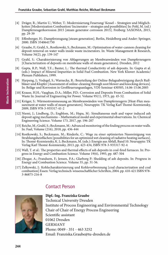
Dipl.-Ing. Franziska Graube Technical University Dresden Institute of Process Engineering and Environmental Technology Chair of Chair of Energy Process Engineering Scientific assistant 01062 Dresden GERMANY Phone: 0049 - 351 - 463 3252 Email: [email protected]
Vorwort
4
Bibliografische Information der Deutschen Nationalbibliothek
Die Deutsche Nationalbibliothek verzeichnet diese Publikation in der Deutschen Nationalbibliografie; detaillierte bibliografische Daten sind im Internet über http://dnb.dnb.de abrufbar
Thiel, S.; Thomé-Kozmiensky, E.; Winter, F.; Juchelková, D. (Eds.):
Waste Management, Volume 8 – Waste-to-Energy –
ISBN 978-3-944310-42-8 Thomé-Kozmiensky Verlag GmbH
Copyright: Elisabeth Thomé-Kozmiensky, M.Sc., Dr.-Ing. Stephanie ThielAll rights reservedPublisher: Thomé-Kozmiensky Verlag GmbH • Neuruppin 2018Editorial office: Dr.-Ing. Stephanie Thiel, Dr.-Ing. Olaf Holm, Elisabeth Thomé-Kozmiensky, M.Sc.Layout: Janin Burbott-Seidel, Ginette Teske, Roland Richter, Cordula Müller, Sarah Pietsch, Gabi Spiegel, Lena BischkopfPrinting: Universal Medien GmbH, Munich
This work is protected by copyright. The rights founded by this, particularly those of translation, reprinting, lecturing, extraction of illustrations and tables, broadcasting, micro-filming or reproduction by other means and storing in a retrieval system, remain reserved, even for exploitation only of excerpts. Reproduction of this work or of part of this work, also in individual cases, is only permissible within the limits of the legal provisions of the copyright law of the Federal Republic of Germany from 9 September 1965 in the currently valid revision. There is a fundamental duty to pay for this. Infringements are subject to the penal provisions of the copyright law.The repeating of commonly used names, trade names, goods descriptions etc. in this work does not permit, even without specific mention, the assumption that such names are to be considered free under the terms of the law concerning goods descriptions and trade mark protection and can thus be used by anyone.Should reference be made in this work, directly or indirectly, to laws, regulations or guide-lines, e.g. DIN, VDI, VDE, VGB, or these are quoted from, then the publisher cannot ac-cept any guarantee for correctness, completeness or currency. It is recommended to refer to the complete regulations or guidelines in their currently valid versions if required for ones own work.