Embed Size (px)
Citation preview
1IEEE 802.1 interim, January, 2004Connection Management for Service Providers, Rev. 2
Metro EthernetConnection ManagementSubmitted to IEEE 802.1 Interim meeting
Vancouver, BC, January 12-15, 2004Norman Finn

2IEEE 802.1 interim, January, 2004Connection Management for Service Providers, Rev. 2
Overview
333IEEE 802.1 interim, January, 2004Connection Management for Service Providers, Rev. 2
What is Metro EthernetConnection Management?
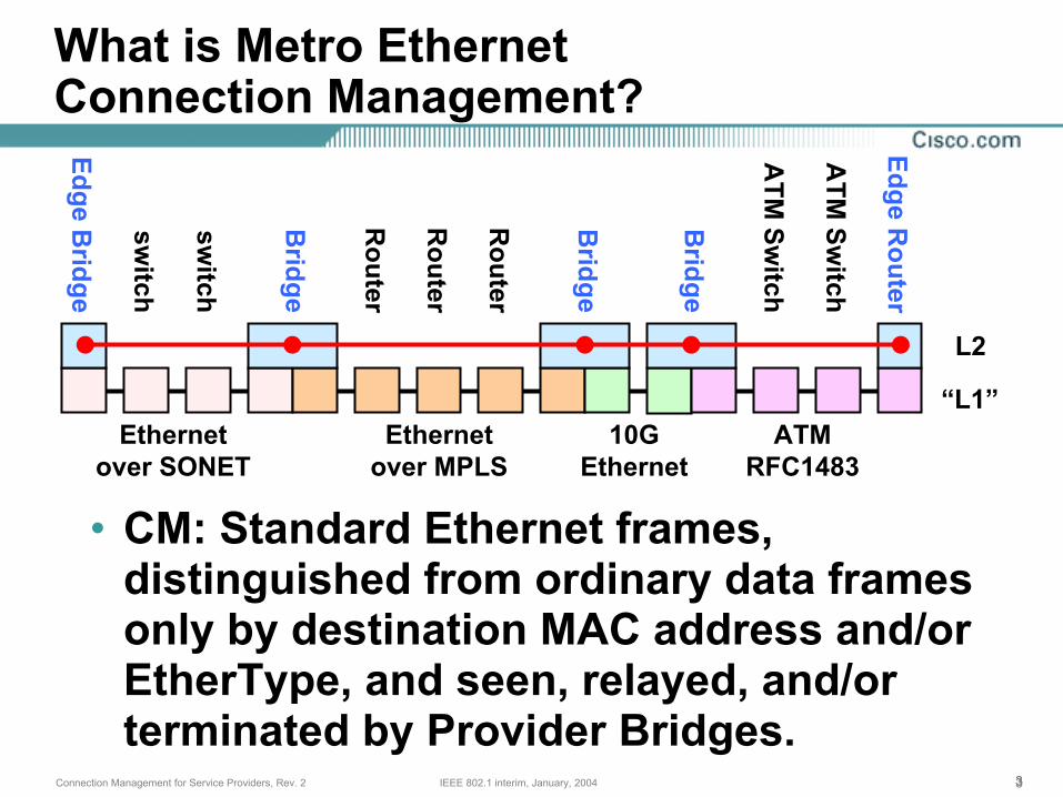
• CM: Standard Ethernet frames, distinguished from ordinary data frames only by destination MAC address and/or EtherType, and seen, relayed, and/or terminated by Provider Bridges.
L2
“L1”Ethernet
over SONETEthernet
over MPLS10G
EthernetATM
RFC1483
Edge Bridge
Bridge
Bridge
Bridge
Edge Router
switch
switch
Router
Router
Router
ATM
Switch
ATM
Switch
444IEEE 802.1 interim, January, 2004Connection Management for Service Providers, Rev. 2
Why do Service Providers wantConnection Management?
• Debugging Layer 2 networks is not easy in the Enterprise space.
• Debugging networks of Layer 2 networks promises to be even harder.
• Especially when the component networks belong to different organizations and/or different companies.
• Experience in providing circuit-based services provides a very useful model for managing and debugging nets of nets.
555IEEE 802.1 interim, January, 2004Connection Management for Service Providers, Rev. 2
What is EthernetConnection Management?
• Connection Management is “E2E OAM”.
• Metro E2E OAM is Ethernet frames, notMPLS, ATM, or SONET frames, cells, or sub-Ethernet control information.
• Only bridges see OAM because bridges are the only active relay functions that exist.
• MPLS, ATM, and SONET OAM are important for debugging Ethernet “wires”, but are not always end-to-end.
666IEEE 802.1 interim, January, 2004Connection Management for Service Providers, Rev. 2
(Terminology issue) There is no such thing as a “Metro Ethernet Edge Router”
• If interoperability is to be achieved among the various technologies used for Metro Ethernet, the IEEE 802 LAN architecture must be observed.
• There are only two kinds of active relay elements in IEEE 802: Bridges and Hubs (Repeaters).
• A “Metro Ethernet Edge Router” is a Bridge that does not need to run spanning tree, has only two ports per VLAN enabled (one trunk and one local Ethernet), and uses Pseudowires for trunks.
• (This notion saves a lot of verbiage in this document. Whether a box is a router or a bridge depends on which function you are looking at.)
777IEEE 802.1 interim, January, 2004Connection Management for Service Providers, Rev. 2
Maintenance and other OAM issuesnot discussed
• Minimal discussion of Provider-to-Customer (single-link) IEEE 802.3ah OAM.
• No explanation of MPLS, ATM, or other OAM.
• No explanation of other techniques such as periodic confirmation of network topology and configuration, SNMP-based “traceroute”, or Layer 3 functions such as Ping.
• No explanation of other protocols such as Ethernet Line Management Interface, BPDUs, etc.
888IEEE 802.1 interim, January, 2004Connection Management for Service Providers, Rev. 2
Two standards bodies are defining end-to-end OAM
• IEEE 802.1ad defines Q-in-Q “Provider Bridges”. IEEE 802.1ag defines end-to-end Ethernet OAM for those Bridges.
• ITU-T Question 3, Study Group 13, is defining end-to-end Ethernet OAM for both circuit-switched equipment (e.g. Ether-over-SONET) and packet-switched equipment (802.1ad Bridges).
• Both 802.1 and Q.3/13 share common membership and are cooperating fully.
802.1 should define low-level aspects tied closely to bridging technology.Q.3/13 should define high-level aspects tied to the service models.
9IEEE 802.1 interim, January, 2004Connection Management for Service Providers, Rev. 2
Domains,Maintenance Levels,
andFlow Points
101010IEEE 802.1 interim, January, 2004Connection Management for Service Providers, Rev. 2
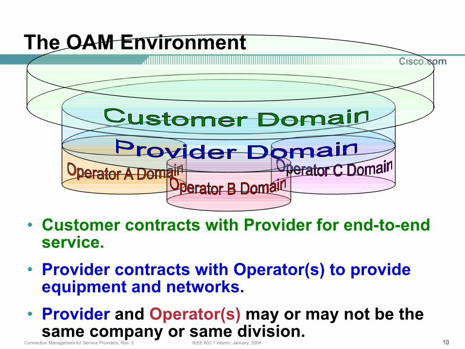
• Customer contracts with Provider for end-to-end service.
• Provider contracts with Operator(s) to provide equipment and networks.
• Provider and Operator(s) may or may not be the same company or same division.
The OAM Environment
111111IEEE 802.1 interim, January, 2004Connection Management for Service Providers, Rev. 2
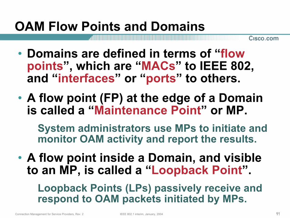
• Domains are defined in terms of “flow points”, which are “MACs” to IEEE 802, and “interfaces” or “ports” to others.
• A flow point (FP) at the edge of a Domain is called a “Maintenance Point” or MP.
System administrators use MPs to initiate and monitor OAM activity and report the results.
• A flow point inside a Domain, and visible to an MP, is called a “Loopback Point”.
Loopback Points (LPs) passively receive and respond to OAM packets initiated by MPs.
OAM Flow Points and Domains
121212IEEE 802.1 interim, January, 2004Connection Management for Service Providers, Rev. 2
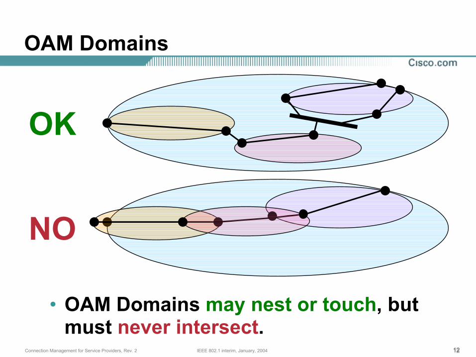
• OAM Domains may nest or touch, but must never intersect.
OAM Domains
OK
NO
131313IEEE 802.1 interim, January, 2004Connection Management for Service Providers, Rev. 2
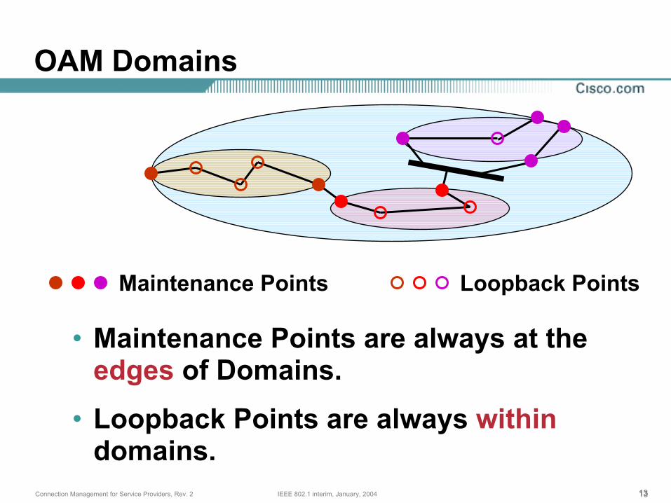
• Maintenance Points are always at the edges of Domains.
• Loopback Points are always withindomains.
OAM Domains
Maintenance Points Loopback Points
141414IEEE 802.1 interim, January, 2004Connection Management for Service Providers, Rev. 2
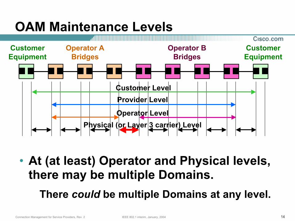
• At (at least) Operator and Physical levels, there may be multiple Domains.
There could be multiple Domains at any level.
OAM Maintenance LevelsCustomerEquipment
CustomerEquipment
Operator ABridges
Operator BBridges
Customer LevelProvider Level
Operator LevelPhysical (or Layer 3 carrier) Level
151515IEEE 802.1 interim, January, 2004Connection Management for Service Providers, Rev. 2
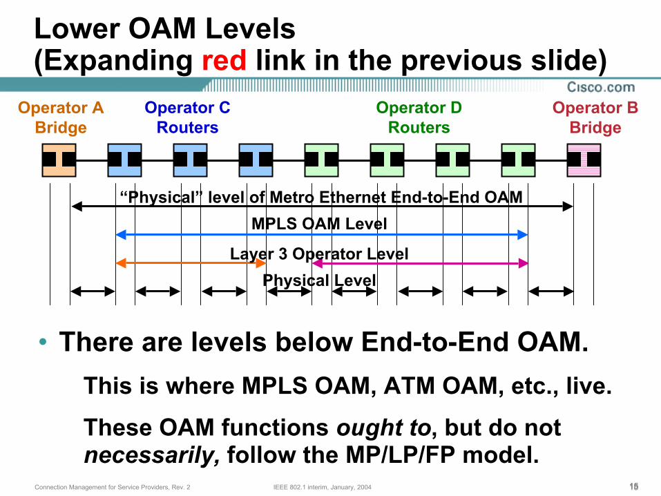
• There are levels below End-to-End OAM.This is where MPLS OAM, ATM OAM, etc., live.
These OAM functions ought to, but do not necessarily, follow the MP/LP/FP model.
Lower OAM Levels(Expanding red link in the previous slide)
Operator ABridge
Operator BBridge
“Physical” level of Metro Ethernet End-to-End OAMMPLS OAM Level
Layer 3 Operator LevelPhysical Level
Operator CRouters
Operator DRouters
161616IEEE 802.1 interim, January, 2004Connection Management for Service Providers, Rev. 2
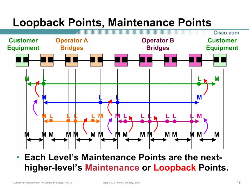
• Each Level’s Maintenance Points are the next-higher-level’s Maintenance or Loopback Points.
Loopback Points, Maintenance PointsCustomerEquipment
CustomerEquipment
Operator ABridges
Operator BBridges
M M
M M
M M M M
M M M M MM M M M M MM M M M M
L
LL
L
L LL L L LL L L L
171717IEEE 802.1 interim, January, 2004Connection Management for Service Providers, Rev. 2
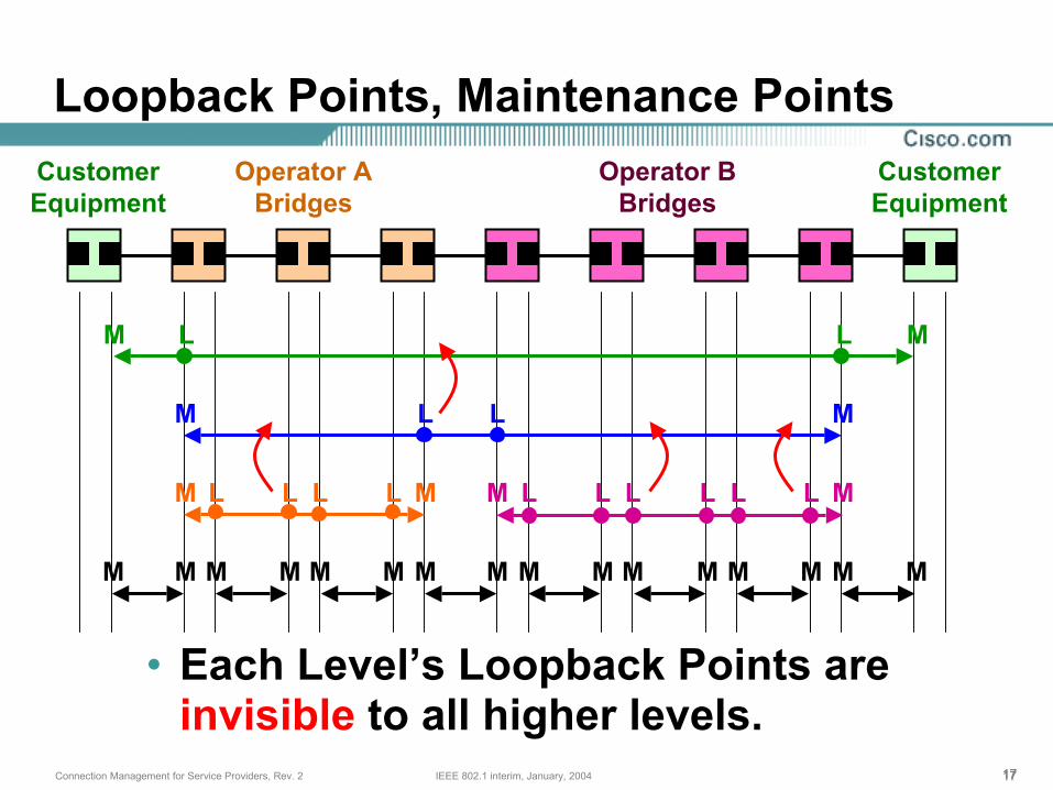
• Each Level’s Loopback Points are invisible to all higher levels.
CustomerEquipment
CustomerEquipment
Operator ABridges
Operator BBridges
Loopback Points, Maintenance Points
M M
M M
M M M M
M M M M MM M M M M MM M M M M
L
LL
L
L LL L L LL L L L
181818IEEE 802.1 interim, January, 2004Connection Management for Service Providers, Rev. 2
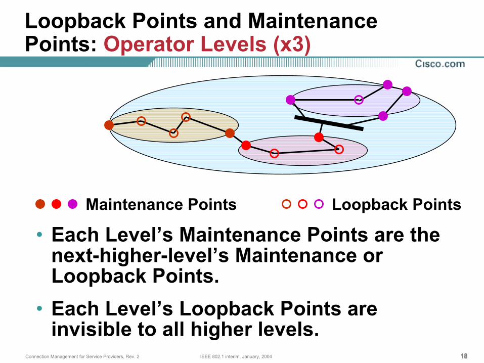
• Each Level’s Maintenance Points are the next-higher-level’s Maintenance or Loopback Points.
• Each Level’s Loopback Points are invisible to all higher levels.
Loopback Points and Maintenance Points: Operator Levels (x3)
Maintenance Points Loopback Points
191919IEEE 802.1 interim, January, 2004Connection Management for Service Providers, Rev. 2
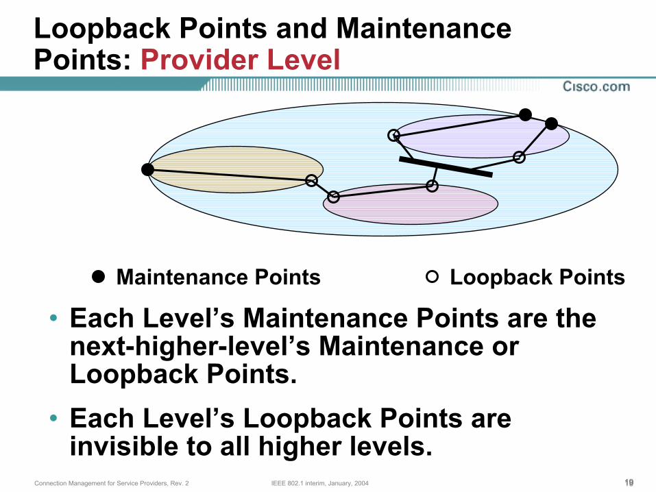
Loopback Points and Maintenance Points: Provider Level
Maintenance Points Loopback Points
• Each Level’s Maintenance Points are the next-higher-level’s Maintenance or Loopback Points.
• Each Level’s Loopback Points are invisible to all higher levels.
20IEEE 802.1 interim, January, 2004Connection Management for Service Providers, Rev. 2
End-to-End OAM Packet Types
212121IEEE 802.1 interim, January, 2004Connection Management for Service Providers, Rev. 2
Three Kinds of OAM Packets
• Continuity CheckMulticast from MP. Received by MPs and LPs. Catalogued by receiving MPs.
• TracerouteNext-hop Multicast from MP to next MP or LP along route. Receiver both replies with unicast to original MP, and sends Traceroute to next MP/LP.
• Loopback (Ping)Unicast from MP to LP or MP, which replies with unicast to originating MP.
222222IEEE 802.1 interim, January, 2004Connection Management for Service Providers, Rev. 2
All OAM Packets must include
• Destination MAC addr (uni- or multicast).• Source MAC addr of sending Flow Point.• Customer Service Instance (CSI) indicator,
typically an S-VLAN ID in an 802.1ad tag.• EtherType, Version, and Op-code.• Maintenance Level indicator (an integer).• Transaction Identifier (an integer).• Universally unique CSI identifier string
(UUCSIID).
232323IEEE 802.1 interim, January, 2004Connection Management for Service Providers, Rev. 2
All OAM Packets may include
• Arbitrary amount of arbitrary data.Data MUST NOT be interpreted by replying FP.
Supports testing frame size limitations and testing of Service Level Agreements.
• Internal Checksum computed on all of frame except .1Q/.1ad tags, which are subject to alteration.
This may detect bad FCS hardware.
242424IEEE 802.1 interim, January, 2004Connection Management for Service Providers, Rev. 2
Continuity Check: Transmission
• Transmitted periodically from each Maintenance Point on each CSI (S-VLAN).
• Timing depends on administrators’ needs; perhaps 1 second intervals, perhaps 60.
• Contains the basic info, plus (at least) an MP Identifier (MPID) unique over CSI, a “validity time” of 2.5 or 3.5 times the transmission period, and port state info.
• There is one standard reserved Continuity Check multicast destination MAC address defined for each Maintenance Level.
252525IEEE 802.1 interim, January, 2004Connection Management for Service Providers, Rev. 2
Continuity Check: Transmission
• Separate CCs are used at every level, from each MP (one bridge may have multiple MPs for same CSI), for each CSI.
• Transaction ID is initialized to random value, incremented once per transmission from a given MP, CSI, and Level.
• Failure detection speed must be balanced against CC loss rate and overhead.
E.g. Validity time of 2.5 transmission interval allows loss of 1 CC.
262626IEEE 802.1 interim, January, 2004Connection Management for Service Providers, Rev. 2
Continuity Check: Reception
• Received in each Maintenance Point at the Maintenance Level and on the CSI of the sender.
• No reply is made to a Continuity Check.
• Received information is saved in a table indexed by MPID for use by Traceroute or Ethernet Line Management Interface (ELMI).
• If validity time of a table entry expires, saved information is discarded.
272727IEEE 802.1 interim, January, 2004Connection Management for Service Providers, Rev. 2
Continuity Check: Errors Detected
• Receiver may compare list of saved MPIDs to a configured list, and complain of mismatches.
• A CC received with a UUCSIID / S-VLAN mismatch indicates cross-connected CSIs.
• Duplicate or out-of-order Transaction IDs may indicate a forwarding loop in Provider space.
• Port state is communicated to all MPs for relay to the customer via ELMI.
282828IEEE 802.1 interim, January, 2004Connection Management for Service Providers, Rev. 2
Continuity Check: Loopback Points
• Loopback Points also receive Continuity Checks.
• Unlike MPs, LPs need not log CCs by source MP.
• LPs remember only the source MAC address, Maintenance Level, S-VLAN, and ingress bridge port in a (software?) CC database separate from the bridge’s main Filtering Database (L2 forwarding table).
• This information is used by the Traceroutefunction.
292929IEEE 802.1 interim, January, 2004Connection Management for Service Providers, Rev. 2
Traceroute Message Initiation
• Originator MP initiates Traceroute Message (TM). Included in packet are:
Target MAC address, always a Maintenance Point
Originator’s MAC address
• TM also includes a Hop Count TLV.
• There is one standard reserved Traceroutemulticast destination MAC address defined for each Maintenance Level.
(For tracing at higher Maintenance Levels.)
303030IEEE 802.1 interim, January, 2004Connection Management for Service Providers, Rev. 2
Traceroute Message forwarding
• All MPs and LPs at a given level intercept all TMs at that level, using destination MAC address.
• Each MP or LP intercepting a TM:1. If TTL is not 0, decrements TTL and:
2. Sends unicast Traceroute Reply (TR) to Originator MP.
3. If TTL still not 0, forwards the TM to next hop along path to target MAC address.
313131IEEE 802.1 interim, January, 2004Connection Management for Service Providers, Rev. 2
Traceroute MessageNext Hop determination
• The bridge looks up the target MAC address in the Filtering Database to find the egress FP.
• If not found, the Continuity Check database is examined.
• If the egress FP matches the ingress FP, then no Traceroute Reply is returned.(This prevents multiple answers after hopping
over a shared medium.)
• Else, the next hop cannot be found.
323232IEEE 802.1 interim, January, 2004Connection Management for Service Providers, Rev. 2
Traceroute Reply
• Traceroute Reply always contains the TTL value, after decrementing, of the intercepted Traceroute Message, the Transaction ID, the device ID of the replying bridge that owns the FP, and the replying bridge’s Layer 3 management address, all in 802.1ab LLDP format.
• In theory, TR comes from a Flow Point, not a Bridge’s brain. Therefore, a Bridge may issue either two TRs for the ingress and egress FPs, or one TR for both.
ObsoleteSlide!
333333IEEE 802.1 interim, January, 2004Connection Management for Service Providers, Rev. 2
Traceroute Reply Contents:Flow Point at ingress to Bridge
• Ingress Flow Point ID and Type and Egress Flow Point ID, in LLDP format.
• Reason for not forwarding TM, either:Ingress FP’s STP/VLAN state is not Forwarding;Ingress FP’s ifOperState is not UP;Data frame would be filtered on ingress;Traceroute Message’s TTL expired;Data frame would be filtered by relay function; orNo egress FP could be identified.
• If forwarded, method for finding Egress FP, either:
Egress FP from Filtering Database; orEgress FP from Continuity Check database.
ObsoleteSlide!
343434IEEE 802.1 interim, January, 2004Connection Management for Service Providers, Rev. 2
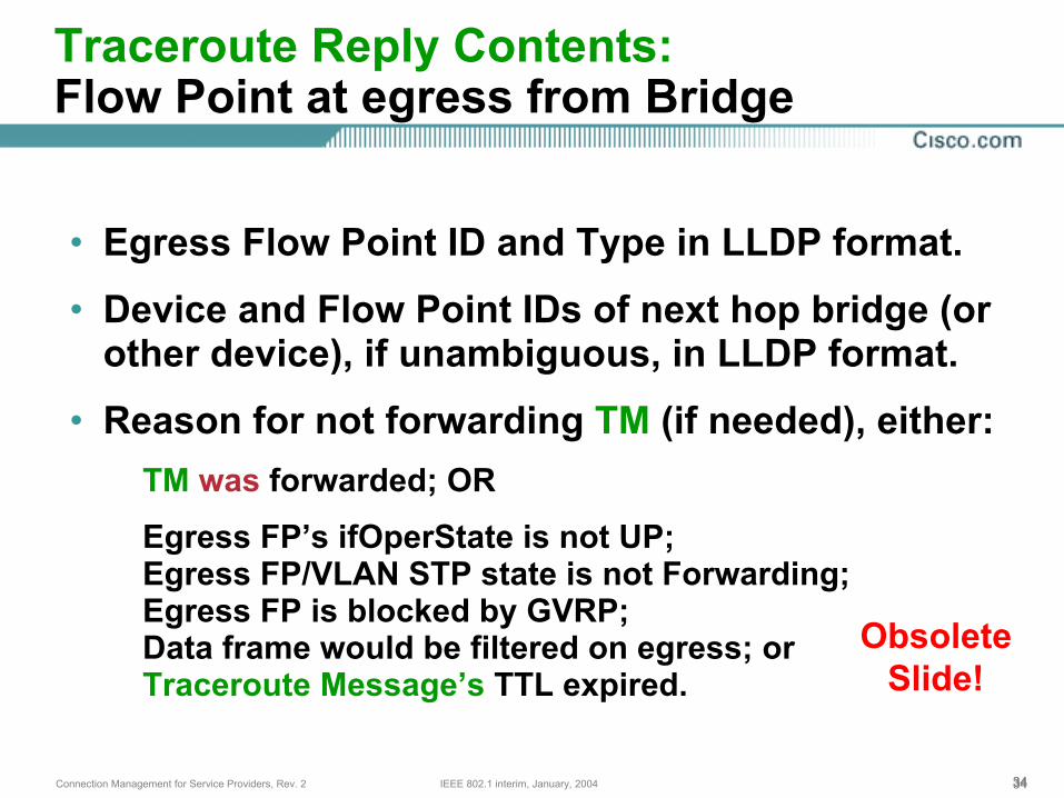
Traceroute Reply Contents:Flow Point at egress from Bridge
• Egress Flow Point ID and Type in LLDP format.
• Device and Flow Point IDs of next hop bridge (or other device), if unambiguous, in LLDP format.
• Reason for not forwarding TM (if needed), either:TM was forwarded; OR
Egress FP’s ifOperState is not UP;Egress FP/VLAN STP state is not Forwarding;Egress FP is blocked by GVRP;Data frame would be filtered on egress; orTraceroute Message’s TTL expired.
ObsoleteSlide!
353535IEEE 802.1 interim, January, 2004Connection Management for Service Providers, Rev. 2
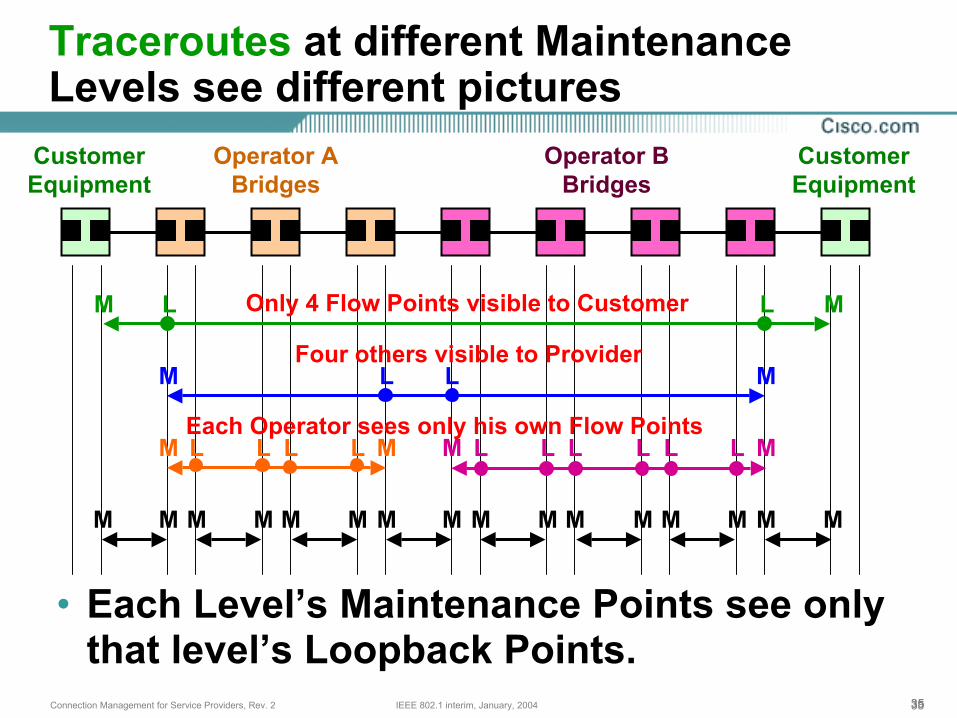
• Each Level’s Maintenance Points see only that level’s Loopback Points.
Traceroutes at different Maintenance Levels see different pictures
CustomerEquipment
CustomerEquipment
Operator ABridges
Operator BBridges
M M
M M
M M M M
M M M M MM M M M M MM M M M M
L
LL
L
L LL L L LL L L L
Only 4 Flow Points visible to Customer
Four others visible to Provider
Each Operator sees only his own Flow Points
363636IEEE 802.1 interim, January, 2004Connection Management for Service Providers, Rev. 2
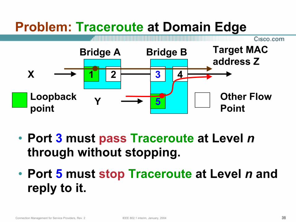
Problem: Traceroute at Domain Edge
• Port 3 must pass Traceroute at Level nthrough without stopping.
• Port 5 must stop Traceroute at Level n and reply to it.
2 3 4
Target MACaddress Z
Loopback point
1
5
X
Y Other Flow Point
Bridge A Bridge B
373737IEEE 802.1 interim, January, 2004Connection Management for Service Providers, Rev. 2
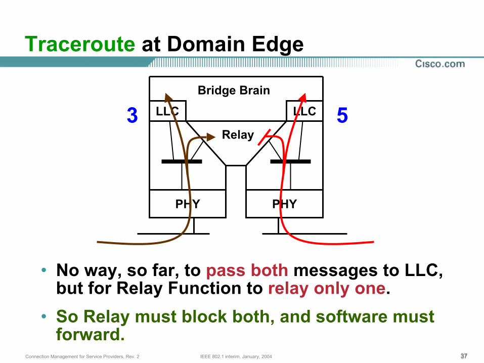
Traceroute at Domain Edge
• No way, so far, to pass both messages to LLC, but for Relay Function to relay only one.
• So Relay must block both, and software must forward.
LLC LLC
Relay
PHY PHY
Bridge Brain
53
383838IEEE 802.1 interim, January, 2004Connection Management for Service Providers, Rev. 2
Loopback Message and Loopback Reply
• Always sent by an MP only to a unicast MAC address of another MP or LP.
Address is obtained from a previous Continuity Check or Traceroute operation.
• Receiving MP or LP responds with a Loopback Reply, which has a different Op-code.
All optional fields are returned in the Loopback Reply.
• Transaction ID allows originating MP to match Loopback Messages to Replies.

39IEEE 802.1 interim, January, 2004Connection Management for Service Providers, Rev. 2
Controlling OAM
404040IEEE 802.1 interim, January, 2004Connection Management for Service Providers, Rev. 2
A Layer 3 overlay is required
• At least one “Customer Service Instance” will be used by the Provider(s) and/or Operator(s) to provider Layer 3 services for managing the bridges.
• This may be a private network, or may be attached to the Big-I Internet.
• Routing functions may be embedded in the Provider Bridges, or may be separate devices.
414141IEEE 802.1 interim, January, 2004Connection Management for Service Providers, Rev. 2
Different organizations may control the same Bridge
• One Operator might provide two UNI ports for two Customers of two different Providers on the same Provider Bridge.
• Although the Operator has the primary responsibility of configuring the Bridge, each Provider requires control of the OAM functions at the Provider Level on those Ports assigned to that Provider as Maintenance Points.
• SNMPv3 is typically the best way to allow a Provider to access OAM controls.
424242IEEE 802.1 interim, January, 2004Connection Management for Service Providers, Rev. 2
Continuity Check Management
• Controls:Transmission period and validity timeOptional TLVs (e.g. interior checksum)Configured list of peer MPsLayer 3 address and options for error reporting
• Reports:Maintenance Level (read-only for CC operator, read/write for Bridge owner/operator)Table of discovered CC informationError conditions
434343IEEE 802.1 interim, January, 2004Connection Management for Service Providers, Rev. 2
Traceroute Management
• Controls:Initiate Traceroute
Select MP (MAC address) to trace
TTL values
Layer 3 address and options for error reporting
• Reports:Traceroute Replies
Error conditions
444444IEEE 802.1 interim, January, 2004Connection Management for Service Providers, Rev. 2
Loopback Management
• Controls:Initiate Loopback sequence
Select FP or MP (MAC address) to ping
Optional TLVs (e.g. arbitrary data)
Layer 3 address and options for error reporting
• Reports:Successful Loopback Replies
Error conditions
45IEEE 802.1 interim, January, 2004Connection Management for Service Providers, Rev. 2
Usage Scenarios
464646IEEE 802.1 interim, January, 2004Connection Management for Service Providers, Rev. 2
Continuity Check is the backbone of OAM
• Continuity Check enables the Ethernet Line Management Interface (ELMI) to report the status of the other UNIs of the service to the Customer.
• Continuity Check also allows MPs to catalog each other, and to associate a MAC address with each other MP.
• MAC addresses of other devices must be discovered via CC, not configured.
Line cards may be swapped. spanning tree paths may change, and MP MAC addresses may be addresses of Ports, and not Brains.
474747IEEE 802.1 interim, January, 2004Connection Management for Service Providers, Rev. 2
Traceroute discovers the Loopback Points
• If CC indicates loss of another MP, Traceroute Message is sent to trace the path from the MP detecting the failure to the saved MAC address of the failed MP.
This may yield the reason for the loss of connectivity.
This will also yield a list of Loopback Points’ MAC addresses to use in Loopback Messages.
• Traceroute may also be used to obtain the list of Loopback Points’ MAC addresses when CC is not indicating any error.
484848IEEE 802.1 interim, January, 2004Connection Management for Service Providers, Rev. 2
Loopback allows detailed checking of paths
• Loopback Messages to successive Loopback Points along the path to another Maintenance Point may detect failures not found by CC or Traceroute.
TM is hop-by-hop, and CC is a multicast. LM/LR are unicast.
LM/LR can be used to detect links with too-small MTUs.
• Loopback may also be used for testing Service Level Agreement compliance: throughput, packet loss rate, etc.
494949IEEE 802.1 interim, January, 2004Connection Management for Service Providers, Rev. 2
Drilling Down
• If the failure can be isolated to a particular link using the above methods, then that link can be debugged.
• If the failing link is not a simple physical link, e.g. it is an Emulated LAN using Pseudowires over MPLS, then the OAM capabilities of that link must be used to debug that link.
50IEEE 802.1 interim, January, 2004Connection Management for Service Providers, Rev. 2
Configuration Information Flow
515151IEEE 802.1 interim, January, 2004Connection Management for Service Providers, Rev. 2
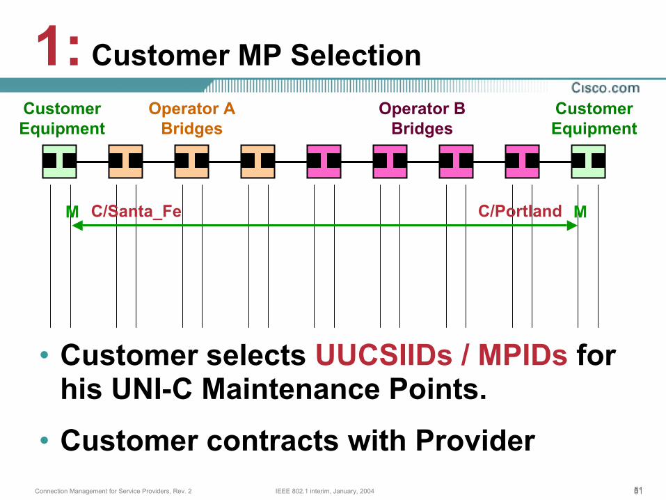
• Customer selects UUCSIIDs / MPIDs for his UNI-C Maintenance Points.
• Customer contracts with Provider
1: Customer MP SelectionCustomerEquipment
CustomerEquipment
Operator ABridges
Operator BBridges
M MC/PortlandC/Santa_Fe
525252IEEE 802.1 interim, January, 2004Connection Management for Service Providers, Rev. 2
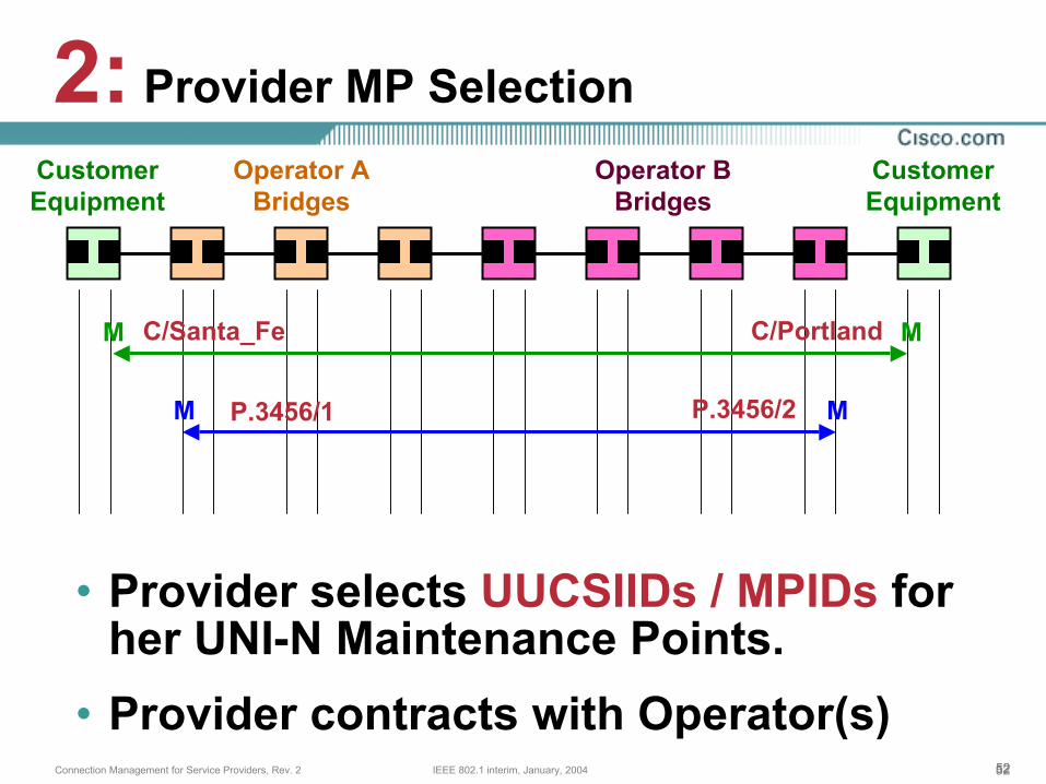
• Provider selects UUCSIIDs / MPIDs for her UNI-N Maintenance Points.
• Provider contracts with Operator(s)
2: Provider MP SelectionCustomerEquipment
CustomerEquipment
Operator ABridges
Operator BBridges
M M
M M
C/PortlandC/Santa_Fe
P.3456/1 P.3456/2
535353IEEE 802.1 interim, January, 2004Connection Management for Service Providers, Rev. 2
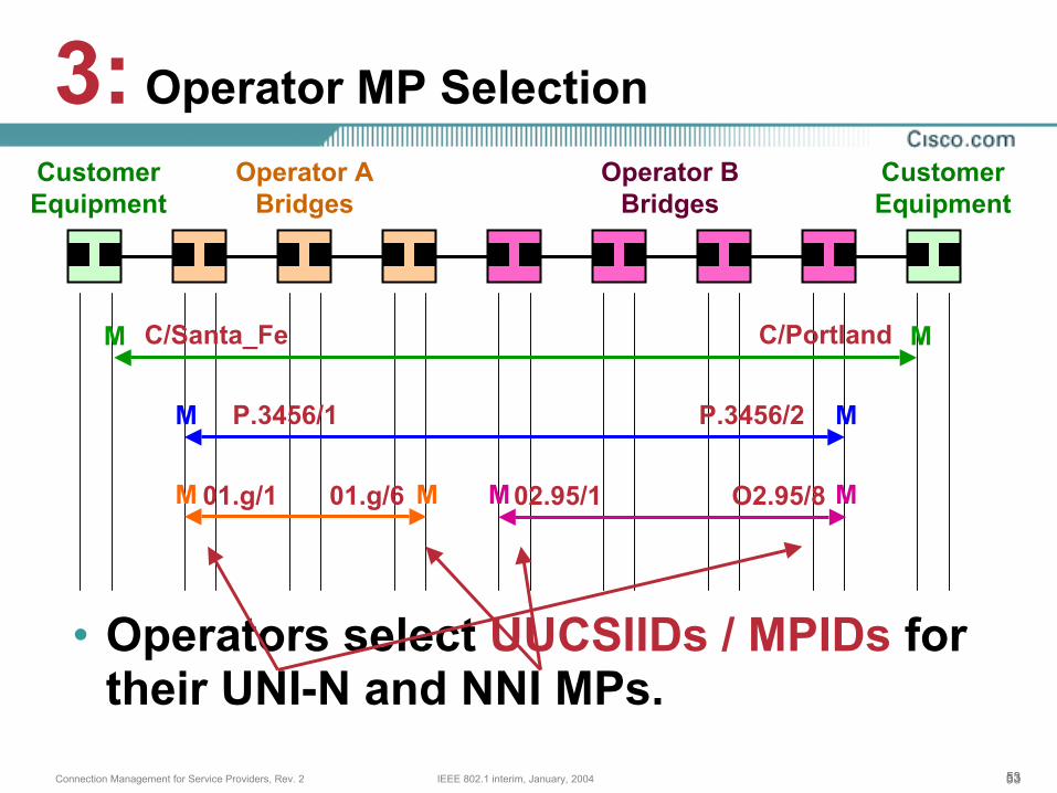
• Operators select UUCSIIDs / MPIDs for their UNI-N and NNI MPs.
3: Operator MP SelectionCustomerEquipment
CustomerEquipment
Operator ABridges
Operator BBridges
M M
M M
C/PortlandC/Santa_Fe
P.3456/1 P.3456/2
M M M M01.g/1 01.g/6 O2.95/802.95/1
545454IEEE 802.1 interim, January, 2004Connection Management for Service Providers, Rev. 2
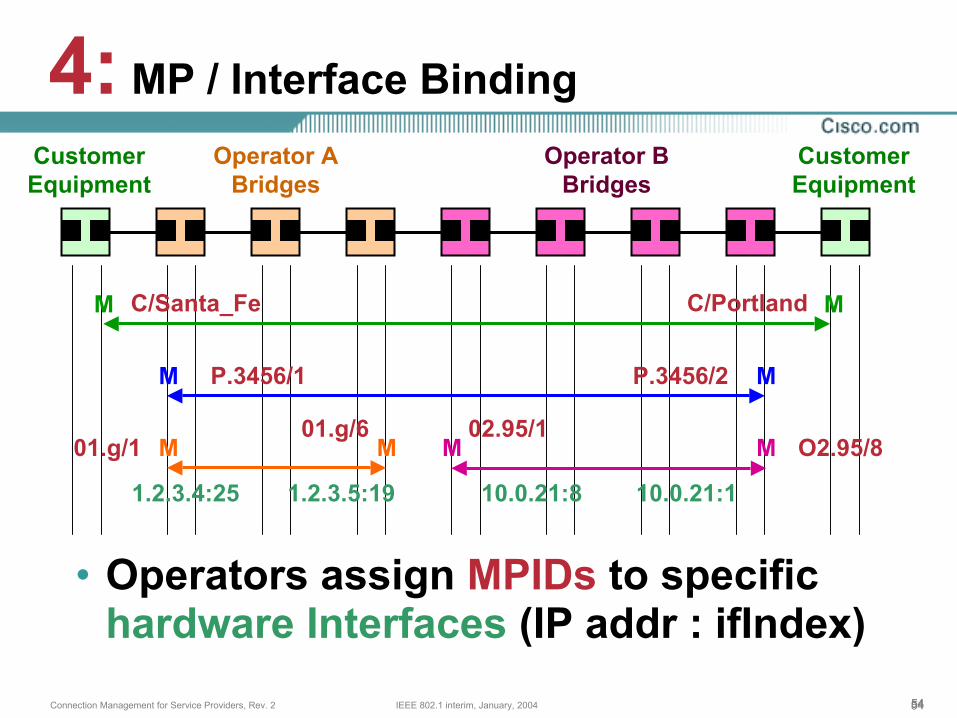
• Operators assign MPIDs to specific hardware Interfaces (IP addr : ifIndex)
4: MP / Interface BindingCustomerEquipment
CustomerEquipment
Operator ABridges
Operator BBridges
M M
M M
C/PortlandC/Santa_Fe
P.3456/1 P.3456/2
M M M M01.g/101.g/6
O2.95/802.95/1
1.2.3.4:25 1.2.3.5:19 10.0.21:8 10.0.21:1

555555IEEE 802.1 interim, January, 2004Connection Management for Service Providers, Rev. 2
• Operators’ MPs discover their LPs’ hardware Interfaces and MAC addrsthrough E2E OAM and start running.
5: Operator LP DiscoveryCustomerEquipment
CustomerEquipment
Operator ABridges
Operator BBridges
M M
M M
C/PortlandC/Santa_Fe
P.3456/1 P.3456/2
M M M M
1.2.3.4:25 1.2.3.5:19 10.0.21:8 10.0.21:1
L LL L L LL L L L01.g/1 O2.95/801.g/6 02.95/1
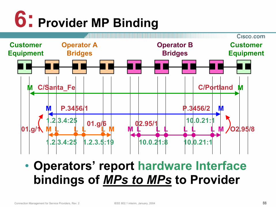
565656IEEE 802.1 interim, January, 2004Connection Management for Service Providers, Rev. 2
• Operators’ report hardware Interfacebindings of MPs to MPs to Provider
6: Provider MP BindingCustomerEquipment
CustomerEquipment
Operator ABridges
Operator BBridges
M M
M M
C/PortlandC/Santa_Fe
P.3456/1 P.3456/2
M M M M
1.2.3.4:25 1.2.3.5:19 10.0.21:8 10.0.21:1
L LL L L LL L L L1.2.3.4:25 10.0.21:1
01.g/1 O2.95/801.g/6 02.95/1
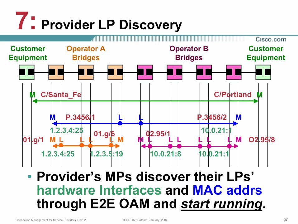
575757IEEE 802.1 interim, January, 2004Connection Management for Service Providers, Rev. 2
• Provider’s MPs discover their LPs’ hardware Interfaces and MAC addrsthrough E2E OAM and start running.
7: Provider LP DiscoveryCustomerEquipment
CustomerEquipment
Operator ABridges
Operator BBridges
M M
M M
C/PortlandC/Santa_Fe
P.3456/1 P.3456/2
M M M M
1.2.3.4:25 1.2.3.5:19 10.0.21:8 10.0.21:1
L LL L L LL L L L1.2.3.4:25 10.0.21:1
LL
01.g/1 O2.95/801.g/6 02.95/1
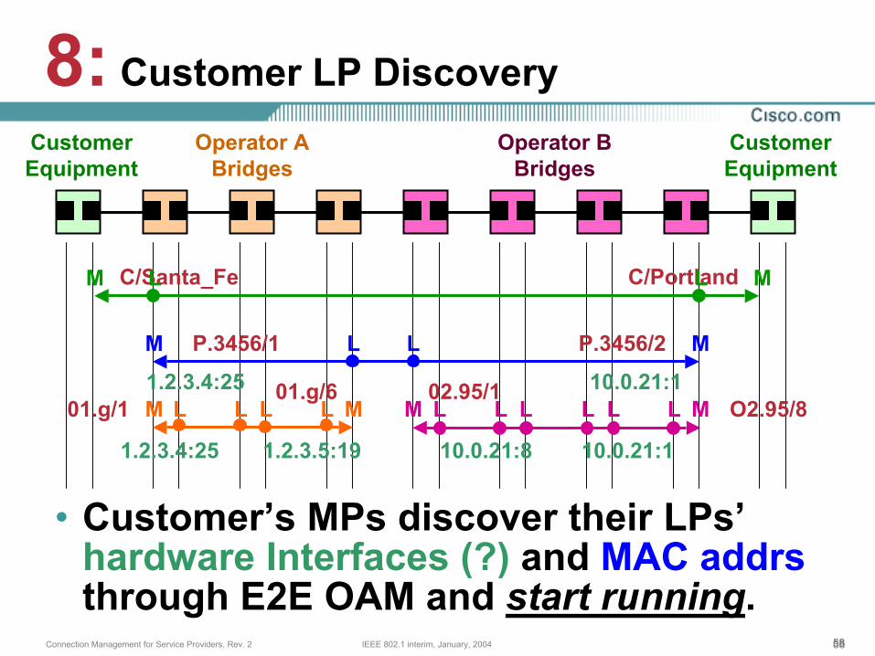
585858IEEE 802.1 interim, January, 2004Connection Management for Service Providers, Rev. 2
• Customer’s MPs discover their LPs’ hardware Interfaces (?) and MAC addrsthrough E2E OAM and start running.
8: Customer LP DiscoveryCustomerEquipment
CustomerEquipment
Operator ABridges
Operator BBridges
M M
M M
C/PortlandC/Santa_Fe
P.3456/1 P.3456/2
M M M M
1.2.3.4:25 1.2.3.5:19 10.0.21:8 10.0.21:1
L LL L L LL L L L1.2.3.4:25 10.0.21:1
LL
L L
01.g/1 O2.95/801.g/6 02.95/1
59IEEE 802.1 interim, January, 2004Connection Management for Service Providers, Rev. 2
Implementation Choices
606060IEEE 802.1 interim, January, 2004Connection Management for Service Providers, Rev. 2
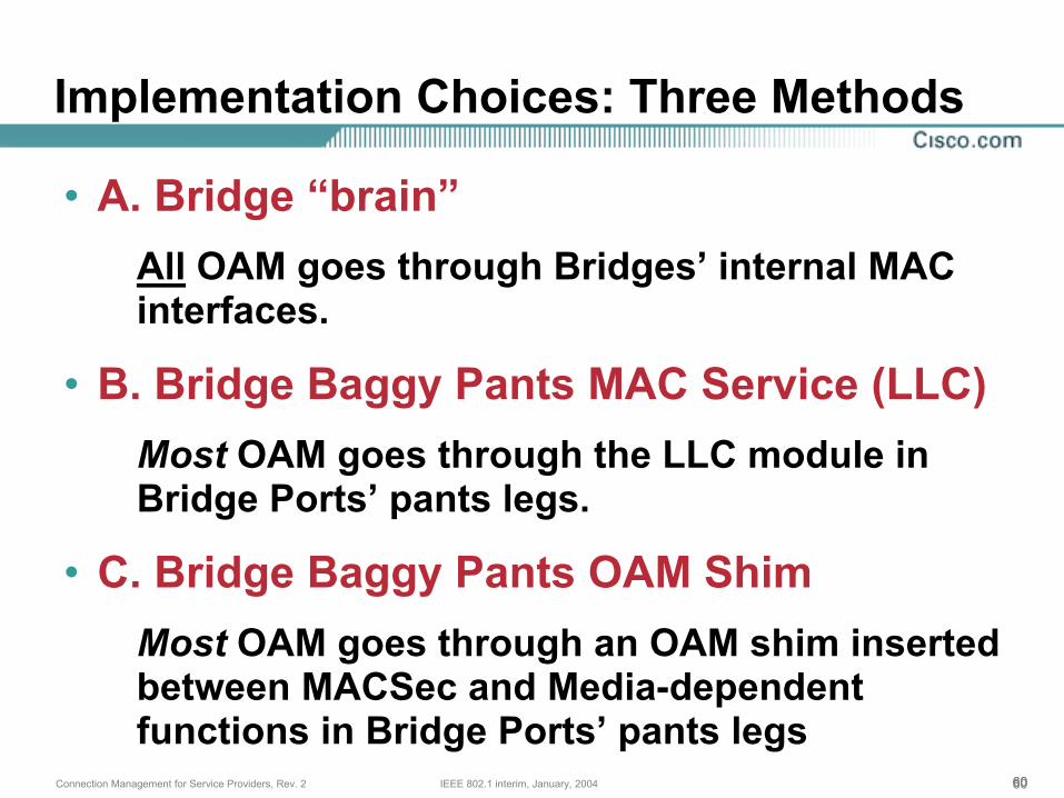
Implementation Choices: Three Methods
• A. Bridge “brain”All OAM goes through Bridges’ internal MAC interfaces.
• B. Bridge Baggy Pants MAC Service (LLC)Most OAM goes through the LLC module in Bridge Ports’ pants legs.
• C. Bridge Baggy Pants OAM ShimMost OAM goes through an OAM shim inserted between MACSec and Media-dependent functions in Bridge Ports’ pants legs
616161IEEE 802.1 interim, January, 2004Connection Management for Service Providers, Rev. 2
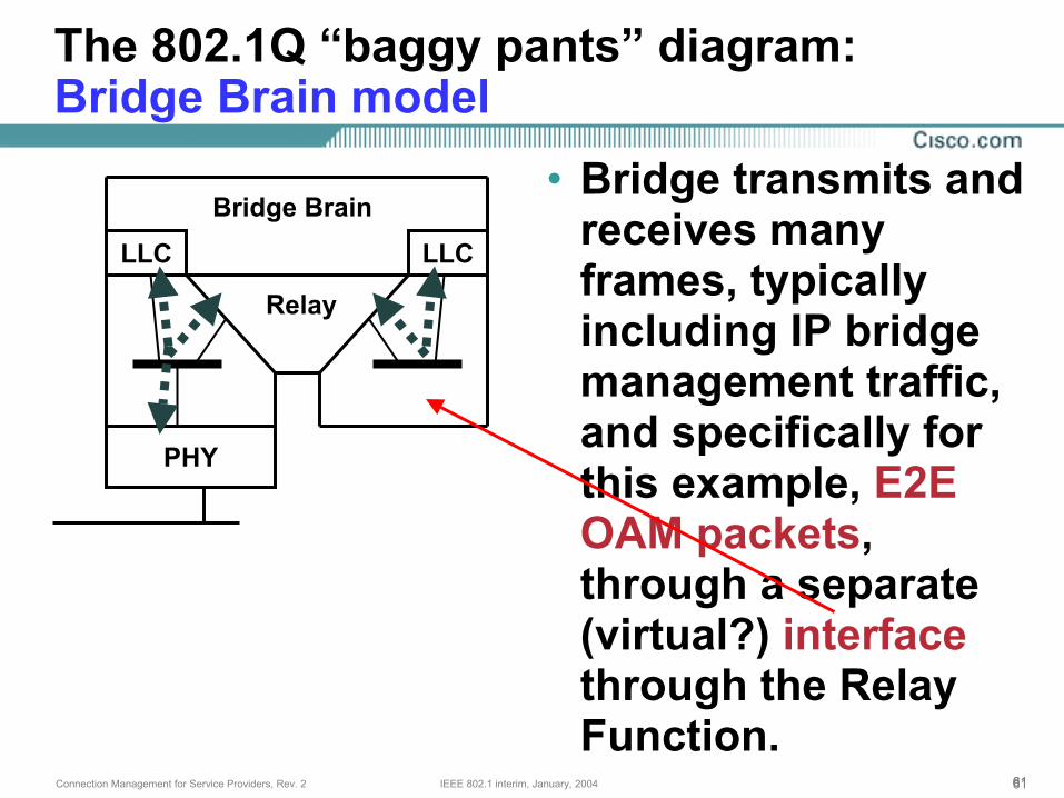
The 802.1Q “baggy pants” diagram:Bridge Brain model
LLC LLC
Relay
PHY
Bridge Brain• Bridge transmits and
receives many frames, typically including IP bridge management traffic, and specifically for this example, E2E OAM packets, through a separate (virtual?) interfacethrough the Relay Function.
626262IEEE 802.1 interim, January, 2004Connection Management for Service Providers, Rev. 2
PHY
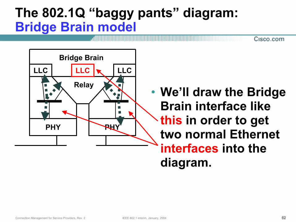
The 802.1Q “baggy pants” diagram:Bridge Brain model
LLC LLC
Relay
PHY
Bridge Brain
• We’ll draw the Bridge Brain interface like this in order to get two normal Ethernet interfaces into the diagram.
LLC

636363IEEE 802.1 interim, January, 2004Connection Management for Service Providers, Rev. 2
PHY
The 802.1Q “baggy pants” diagram:Bridge Brain model
LLC LLC
Relay
PHY
Bridge Brain
LLC
• The OAM packets are all sent through the Bridge Brain port.
646464IEEE 802.1 interim, January, 2004Connection Management for Service Providers, Rev. 2
PHY
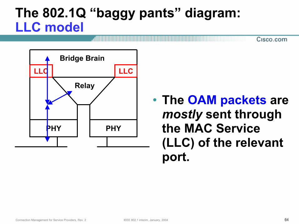
The 802.1Q “baggy pants” diagram:LLC model
LLC LLC
Relay
PHY
Bridge Brain
• The OAM packets are mostly sent through the MAC Service (LLC) of the relevant port.
656565IEEE 802.1 interim, January, 2004Connection Management for Service Providers, Rev. 2
PHY PHY
LLC LLC
Relay
Bridge Brain
OAM ShimOAM Shim
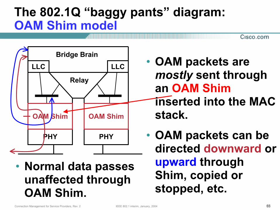
The 802.1Q “baggy pants” diagram:OAM Shim model
• OAM packets are mostly sent through an OAM Shiminserted into the MAC stack.
• OAM packets can be directed downward or upward through Shim, copied or stopped, etc.
• Normal data passes unaffected through OAM Shim.
666666IEEE 802.1 interim, January, 2004Connection Management for Service Providers, Rev. 2
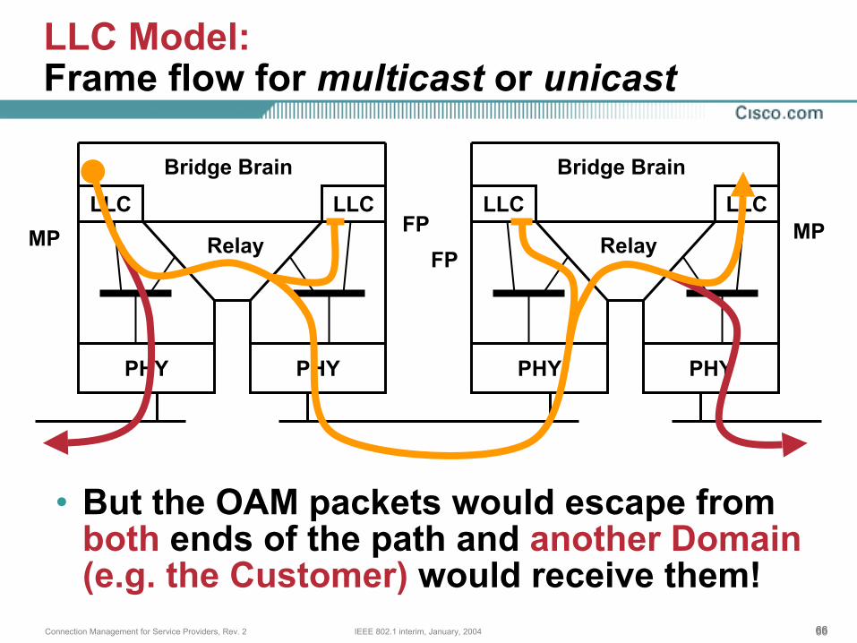
LLC Model:Frame flow for multicast or unicast
• But the OAM packets would escape from both ends of the path and another Domain (e.g. the Customer) would receive them!
LLC LLC
Relay
PHY PHY
Bridge Brain
LLC LLC
Relay
PHY PHY
Bridge Brain
MP MPFPFP
676767IEEE 802.1 interim, January, 2004Connection Management for Service Providers, Rev. 2
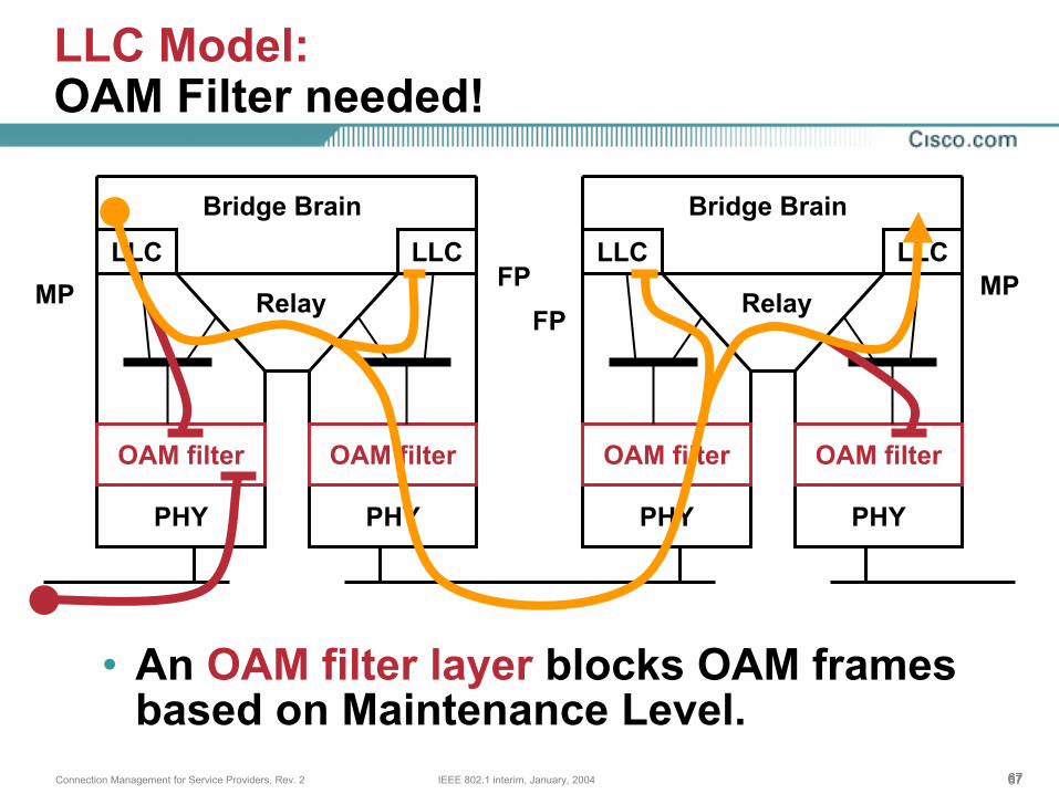
LLC Model:OAM Filter needed!
PHY PHY PHY PHY
OAM filter OAM filter OAM filter OAM filter
• An OAM filter layer blocks OAM frames based on Maintenance Level.
LLC LLC
Relay
Bridge Brain
LLC LLC
Relay
Bridge Brain
MP MPFPFP
686868IEEE 802.1 interim, January, 2004Connection Management for Service Providers, Rev. 2
LLC Model:The “Baggy Pants” OAM Filter
• OAM Filter stops OAM packets that are at or below a certain Maintenance Level.
• Required for Maintenance Points only.• Multicast OAM packets can be filtered by
destination MAC address to achieve almost the same result.
• But the OAM Filter is needed to prevent the inadvertent distribution of OAM packets destined for unknown unicast addresses.
696969IEEE 802.1 interim, January, 2004Connection Management for Service Providers, Rev. 2
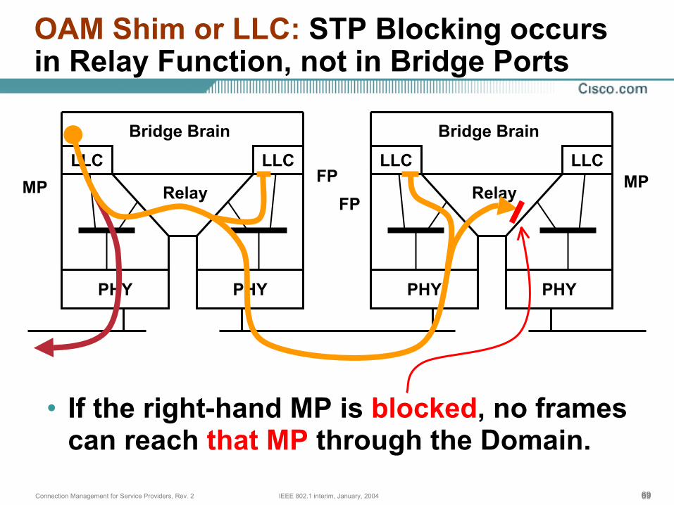
OAM Shim or LLC: STP Blocking occurs in Relay Function, not in Bridge Ports
LLC LLC
Relay
PHY PHY
Bridge Brain
LLC LLC
Relay
PHY PHY
Bridge Brain
MP MPFPFP
• If the right-hand MP is blocked, no frames can reach that MP through the Domain.
707070IEEE 802.1 interim, January, 2004Connection Management for Service Providers, Rev. 2
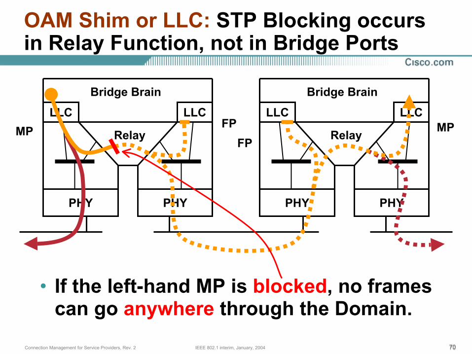
OAM Shim or LLC: STP Blocking occurs in Relay Function, not in Bridge Ports
• If the left-hand MP is blocked, no frames can go anywhere through the Domain.
LLC LLC
Relay
PHY PHY
Bridge Brain
LLC LLC
Relay
PHY PHY
Bridge Brain
MP MPFPFP
717171IEEE 802.1 interim, January, 2004Connection Management for Service Providers, Rev. 2
And if blocked ports are isolated ...
• Blocked Maintenance Points cannot announce the fact that they are ready to work, but not actually in use.
• Blocked Maintenance Points cannot collect lists of other Maintenance Points in preparation for a fast shift to Forwarding.
• Traceroute towards a blocked Maintenance Points cannot reach that MP, and thus cannot send a Traceroute Reply.
• Blocked MPs are not available to anyprotocol from inside the Domain.
727272IEEE 802.1 interim, January, 2004Connection Management for Service Providers, Rev. 2
Bridge Brain, LLC, or OAM Shim models:Must we pick one or the other?
• Whether there is really a difference in path coverage between one or the other depends on the architecture of the bridge.
• Since Ethernets may be virtual, bridge can report the same MAC address for multiple MACs, so one cannot tell whether a bridge is using one or the other method.
• OAM to a blocked port requires the Bridge Brain model.
737373IEEE 802.1 interim, January, 2004Connection Management for Service Providers, Rev. 2
Bridge Brain, LLC, or OAM Shim models:We may observe:
• The only difference between the Bridge Brain and [either the LLC or OAM Shim] model is the MAC address reported by the Maintenance Point or Loopback Point.
• The Configuration Information flow shows that MAC addresses are discovered, not configured.
• MAC addresses (and sometimes, IP:Interface address) are variable, anyway, and must be discovered.
747474IEEE 802.1 interim, January, 2004Connection Management for Service Providers, Rev. 2
The Answer• One may implement any of the three
models, and use that model’s MAC address for most OAM operations.
• One must use either the Bridge Brain model (or use another Port’s LLC port) to access a blocked port via OAM.
• For the purposes of defining an End-to-End OAM protocol, the choice of implementation is irrelevant.
75IEEE 802.1 interim, January, 2004Connection Management for Service Providers, Rev. 2
Summary
767676IEEE 802.1 interim, January, 2004Connection Management for Service Providers, Rev. 2
Metro Ethernet End-to-End OAMon one slide
• Different organizations’ Maintenance Domains are nested in Levels.
• Maintenance Points are active, Loopback Points are passive, other Flow Points are transparent.
• Five kinds of OAM packets: Continuity Check, Traceroute Message / Reply, Loopback Message / Reply.
• Configuration info flow and access to blocked Bridge Ports lead to (at least) 3 interoperable implementation models.
777777IEEE 802.1 interim, January, 2004Connection Management for Service Providers, Rev. 2


![Aluminum Presentation IEEEgrouper.ieee.org/.../AluminumPresentationIEEE[CompatibilityMode].pdf · Evaluation of Aluminum Cable Presentation for IEEE OCS September 14, ... Table C.1;](https://img.pdfslide.net/doc/110x75/5b0dfa9a7f8b9a952f8e4bbb/aluminum-presentation-compatibilitymodepdfevaluation-of-aluminum-cable-presentation.jpg)