Embed Size (px)
Citation preview
Metrode Products Limited
Technical Profiles
October 2009
Metrode Products Limited
Hanworth Lane
Chertsey
Surrey
KT16 9LL
UK
© Metrode Products Ltd Page 1 of 36 Issue 7 September 2009
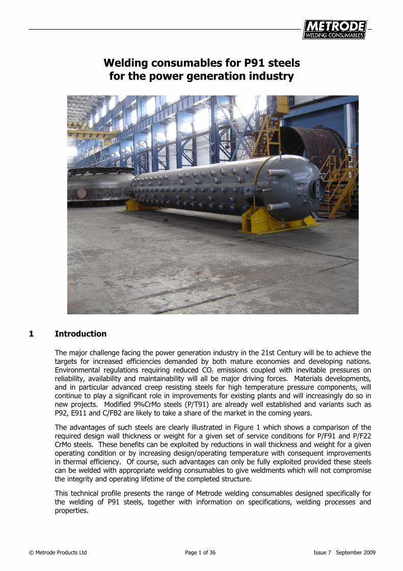
Welding consumables for P91 steels for the power generation industry
1 Introduction
The major challenge facing the power generation industry in the 21st Century will be to achieve the targets for increased efficiencies demanded by both mature economies and developing nations. Environmental regulations requiring reduced CO2 emissions coupled with inevitable pressures on reliability, availability and maintainability will all be major driving forces. Materials developments, and in particular advanced creep resisting steels for high temperature pressure components, will continue to play a significant role in improvements for existing plants and will increasingly do so in new projects. Modified 9%CrMo steels (P/T91) are already well established and variants such as P92, E911 and C/FB2 are likely to take a share of the market in the coming years.
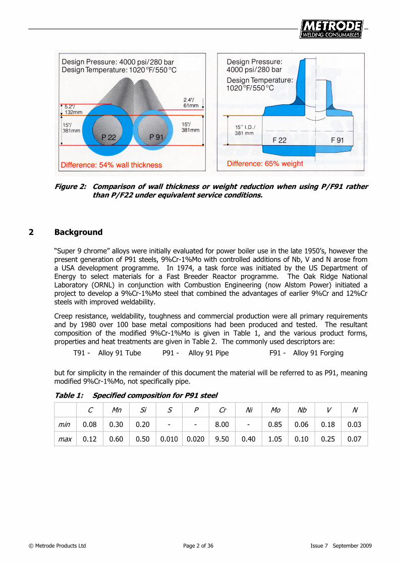
The advantages of such steels are clearly illustrated in Figure 1 which shows a comparison of the required design wall thickness or weight for a given set of service conditions for P/F91 and P/F22 CrMo steels. These benefits can be exploited by reductions in wall thickness and weight for a given operating condition or by increasing design/operating temperature with consequent improvements in thermal efficiency. Of course, such advantages can only be fully exploited provided these steels can be welded with appropriate welding consumables to give weldments which will not compromise the integrity and operating lifetime of the completed structure.
This technical profile presents the range of Metrode welding consumables designed specifically for the welding of P91 steels, together with information on specifications, welding processes and properties.
© Metrode Products Ltd Page 2 of 36 Issue 7 September 2009
Figure 2: Comparison of wall thickness or weight reduction when using P/F91 rather than P/F22 under equivalent service conditions.
2 Background
“Super 9 chrome” alloys were initially evaluated for power boiler use in the late 1950’s, however the present generation of P91 steels, 9%Cr-1%Mo with controlled additions of Nb, V and N arose from a USA development programme. In 1974, a task force was initiated by the US Department of Energy to select materials for a Fast Breeder Reactor programme. The Oak Ridge National Laboratory (ORNL) in conjunction with Combustion Engineering (now Alstom Power) initiated a project to develop a 9%Cr-1%Mo steel that combined the advantages of earlier 9%Cr and 12%Cr steels with improved weldability.
Creep resistance, weldability, toughness and commercial production were all primary requirements and by 1980 over 100 base metal compositions had been produced and tested. The resultant composition of the modified 9%Cr-1%Mo is given in Table 1, and the various product forms, properties and heat treatments are given in Table 2. The commonly used descriptors are:
T91 - Alloy 91 Tube P91 - Alloy 91 Pipe F91 - Alloy 91 Forging
but for simplicity in the remainder of this document the material will be referred to as P91, meaning modified 9%Cr-1%Mo, not specifically pipe.
Table 1: Specified composition for P91 steel
C Mn Si S P Cr Ni Mo Nb V N
min 0.08 0.30 0.20 - - 8.00 - 0.85 0.06 0.18 0.03
max 0.12 0.60 0.50 0.010 0.020 9.50 0.40 1.05 0.10 0.25 0.07
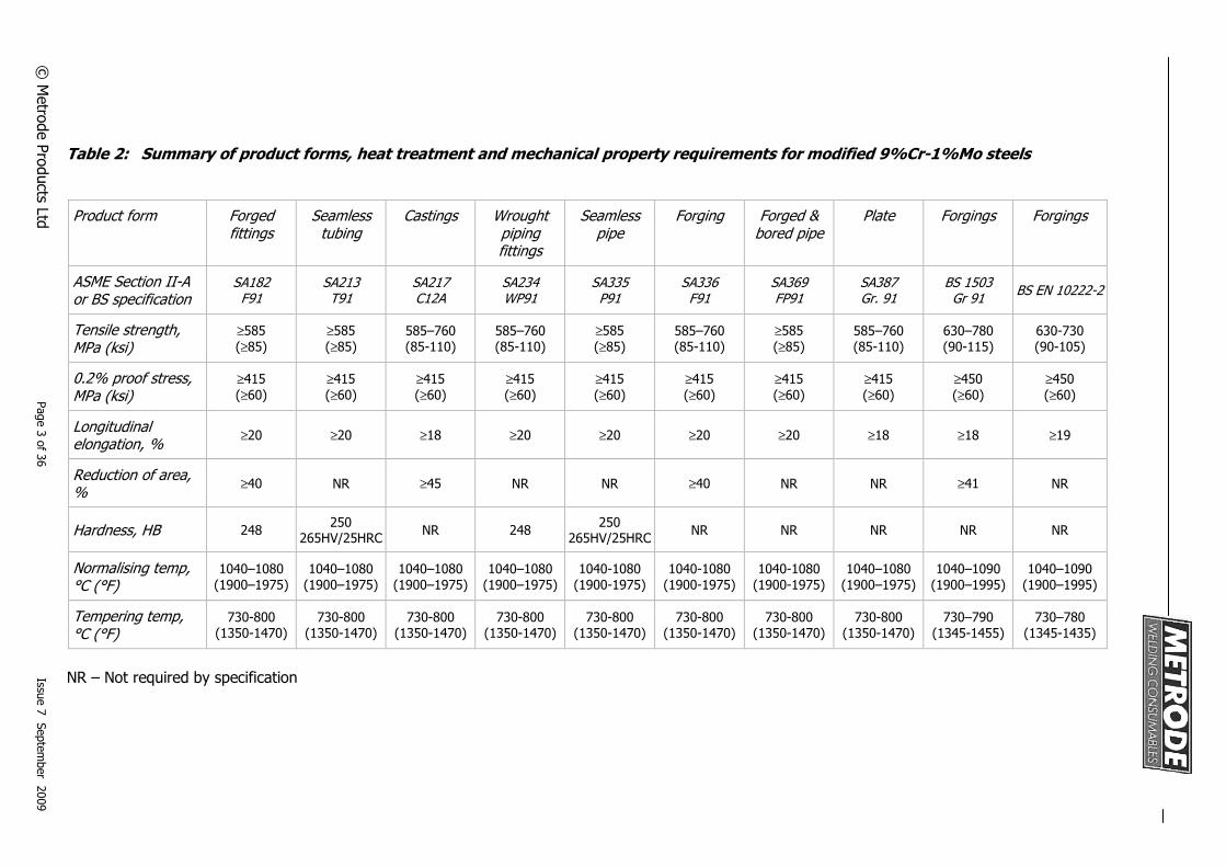
Table 2: Summary of product forms, heat treatment and mechanical property requirements for modified 9%Cr-1%Mo steels
Product form Forged fittings
Seamless tubing
Castings Wrought piping fittings
Seamless pipe
Forging Forged & bored pipe
Plate Forgings Forgings
ASME Section II-A or BS specification
SA182 F91
SA213 T91
SA217 C12A
SA234 WP91
SA335 P91
SA336 F91
SA369 FP91
SA387 Gr. 91
BS 1503 Gr 91
BS EN 10222-2
Tensile strength, MPa (ksi)
≥585
(≥85)
≥585
(≥85)
585–760
(85-110)
585–760
(85-110)
≥585
(≥85)
585–760
(85-110)
≥585
(≥85)
585–760
(85-110)
630–780
(90-115)
630-730
(90-105)
0.2% proof stress, MPa (ksi)
≥415
(≥60)
≥415
(≥60)
≥415
(≥60)
≥415
(≥60)
≥415
(≥60)
≥415
(≥60)
≥415
(≥60)
≥415
(≥60)
≥450
(≥60)
≥450
(≥60)
Longitudinal elongation, %
≥20 ≥20 ≥18 ≥20 ≥20 ≥20 ≥20 ≥18 ≥18 ≥19
Reduction of area, %
≥40 NR ≥45 NR NR ≥40 NR NR ≥41 NR
Hardness, HB 248 250
265HV/25HRC NR 248
250 265HV/25HRC
NR NR NR NR NR
Normalising temp, °C (°F)
1040–1080
(1900–1975)
1040–1080
(1900–1975)
1040–1080
(1900–1975)
1040–1080
(1900–1975)
1040-1080
(1900-1975)
1040-1080
(1900-1975)
1040-1080
(1900-1975)
1040–1080
(1900–1975)
1040–1090
(1900–1995)
1040–1090
(1900–1995)
Tempering temp, °C (°F)
730-800
(1350-1470)
730-800
(1350-1470)
730-800
(1350-1470)
730-800
(1350-1470)
730-800
(1350-1470)
730-800
(1350-1470)
730-800
(1350-1470)
730-800
(1350-1470)
730–790
(1345-1455)
730–780
(1345-1435)
NR – Not required by specification
© M
etro
de
Pro
du
cts Ltd
P
ag
e 3
of 3
6
Issue
7 S
ep
tem
be
r 20
09
© Metrode Products Ltd Page 4 of 36 Issue 7 September 2009
The first set of 9%Cr-1%Mo (modified) trial tubes was installed in superheater sections in May 1980 – replacing type 321 stainless steel tubing. By 1983 the steel was recognised for tubing by ASTM as A213, Grade T91 and by ASTM/ASME for pipe as A/SA-335, Grade P91 in 1984.
By the mid 1980’s, UK interest in the material was developing and the former CEGB established a programme leading to the installation of replacement headers in P91 at West Burton Power Station during 1989.
Development and testing of suitable welding consumables started in 1986, and Metrode was already supplying prototype batches for evaluation by 1987. Metrode commenced commercial production in 1988 and welding consumables to a variety of specifications have been in continuous production and use up to the present time.
In the last twenty years many hundreds of tonnes of Metrode P91 consumables have been supplied worldwide for both repair and upgrading of existing power stations, and for the construction of new units both in the UK and overseas. Research work continues to introduce new products (eg root welding SMAW electrode Chromet 91VNB and matching core wire Chromet 9MVN+), to generate data and to increase our understanding of the welding of P91.
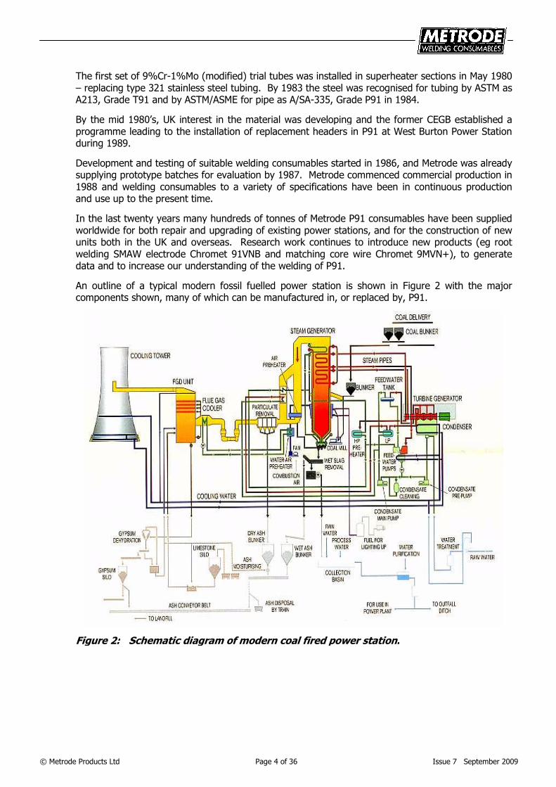
An outline of a typical modern fossil fuelled power station is shown in Figure 2 with the major components shown, many of which can be manufactured in, or replaced by, P91.
Figure 2: Schematic diagram of modern coal fired power station.
© Metrode Products Ltd Page 5 of 36 Issue 7 September 2009
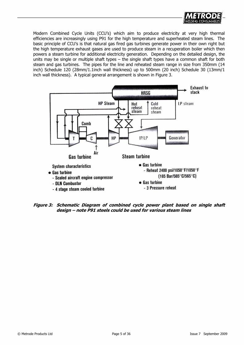
Modern Combined Cycle Units (CCU’s) which aim to produce electricity at very high thermal efficiencies are increasingly using P91 for the high temperature and superheated steam lines. The basic principle of CCU’s is that natural gas fired gas turbines generate power in their own right but the high temperature exhaust gases are used to produce steam in a recuperation boiler which then powers a steam turbine for additional electricity generation. Depending on the detailed design, the units may be single or multiple shaft types – the single shaft types have a common shaft for both steam and gas turbines. The pipes for the line and reheated steam range in size from 350mm (14 inch) Schedule 120 (28mm/1.1inch wall thickness) up to 500mm (20 inch) Schedule 30 (13mm/1 inch wall thickness). A typical general arrangement is shown in Figure 3.
Figure 3: Schematic Diagram of combined cycle power plant based on single shaft design – note P91 steels could be used for various steam lines
© Metrode Products Ltd Page 6 of 36 Issue 7 September 2009
3 Weld metal compositions
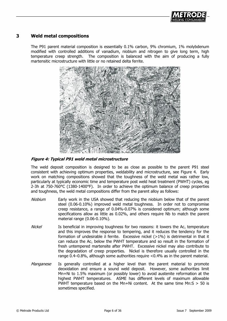
The P91 parent material composition is essentially 0.1% carbon, 9% chromium, 1% molybdenum modified with controlled additions of vanadium, niobium and nitrogen to give long term, high temperature creep strength. The composition is balanced with the aim of producing a fully martensitic microstructure with little or no retained delta ferrite.
Figure 4: Typical P91 weld metal microstructure
The weld deposit composition is designed to be as close as possible to the parent P91 steel consistent with achieving optimum properties, weldability and microstructure, see Figure 4. Early work on matching compositions showed that the toughness of the weld metal was rather low, particularly at typically economic time and temperature post weld heat treatment (PWHT) cycles, eg 2-3h at 750-760°C (1380-1400°F). In order to achieve the optimum balance of creep properties and toughness, the weld metal compositions differ from the parent alloy as follows:
Niobium Early work in the USA showed that reducing the niobium below that of the parent steel (0.06-0.10%) improved weld metal toughness. In order not to compromise creep resistance, a range of 0.04%-0.07% is considered optimum; although some specifications allow as little as 0.02%, and others require Nb to match the parent material range (0.06-0.10%).
Nickel Is beneficial in improving toughness for two reasons: it lowers the Ac1 temperature and this improves the response to tempering, and it reduces the tendency for the
formation of undesirable δ ferrite. Excessive nickel (>1%) is detrimental in that it can reduce the Ac1 below the PWHT temperature and so result in the formation of fresh untempered martensite after PWHT. Excessive nickel may also contribute to the degradation of creep properties. Nickel is therefore usually controlled in the range 0.4–0.8%, although some authorities require <0.4% as in the parent material.
Manganese Is generally controlled at a higher level than the parent material to promote deoxidation and ensure a sound weld deposit. However, some authorities limit Mn+Ni to 1.5% maximum (or possibly lower) to avoid austenite reformation at the highest PWHT temperatures. ASME has different levels of maximum allowable PWHT temperature based on the Mn+Ni content. At the same time Mn:S > 50 is sometimes specified.
© Metrode Products Ltd Page 7 of 36 Issue 7 September 2009
Silicon Is an essential deoxidant and in conjunction with chromium it contributes, in a small way, to the alloy’s oxidation resistance. A low level of Si benefits weld toughness and as a consequence of early work in the USA a limit of 0.30% Si (which is below the parent material range of 0.20–0.50%) was originally adopted in some USA specifications. Most USA consumable specifications now allow 0.5% maximum Si, the same as the base material.
Vanadium Carbon Nitrogen
All have a minor influence on toughness, unless incorrect balance leads to ferrite formation, and weld metal ranges and values are essentially the same as the parent alloy to maintain good creep performance.
Aluminium Is not deliberately added to consumables but a number of engineering specifications now have a requirement of a N:Al ratio ≥ 2. This is now reflected in the analysis of Metrode’s consumables.
4 Consumable specifications
There are national standards covering consumables for all of the major arc welding processes (electrodes for MMA, solid wires for TIG/MIG/sub-arc and finally flux cored wires).
The specification composition ranges from a number of sources are given in Table 3, together with the mechanical property requirements after PWHT in Table 4. The European and USA weld metal specifications are similar to the parent material specifications. The manganese and silicon levels, particularly in the European EN specifications have been broadened to accommodate a number of different manufacturers’ design philosophies. The nickel limits recognise the beneficial effects on toughness with a maximum of 0.8 or up to 1.0% in all specifications and minimum of 0.4% in the BS EN ISO specifications. The minimum levels for the strengthening elements niobium, vanadium and in some cases nitrogen are lowered compared with the parent material specification, this recognises the beneficial effects on toughness and the fact that high levels are not considered to be essential to provide suitably overmatching weld metal strength. The mechanical property requirements of the weld metals are all generally in line with the parent steel except that slightly lower minimum elongations are permitted.
There is some divergence in specified preheat and interpass temperatures for test plates to determine mechanical properties, and also variation in the post weld heat treatment (PWHT) specified in standards. Recent changes to national specifications has tended to bring the preheat and PWHT requirements in line with typical fabrication practice. Fabrications welds typically employ a preheat-interpass range of 200-300°C, and PWHT of 755-760°C for 2-3 hours. PWHT will be discussed further is Section 8.
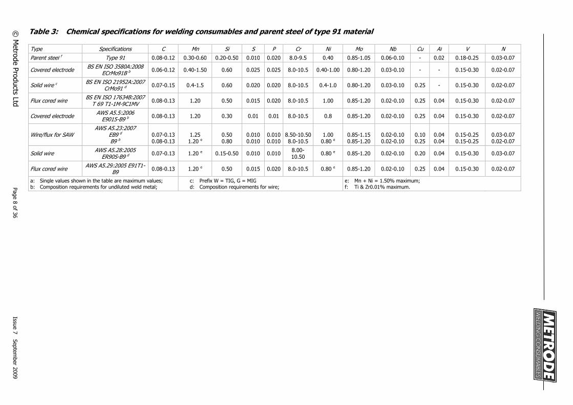
Table 3: Chemical specifications for welding consumables and parent steel of type 91 material
Type Specifications C Mn Si S P Cr Ni Mo Nb Cu Al V N
Parent steel f Type 91 0.08-0.12 0.30-0.60 0.20-0.50 0.010 0.020 8.0-9.5 0.40 0.85-1.05 0.06-0.10 - 0.02 0.18-0.25 0.03-0.07
Covered electrode
BS EN ISO 3580A:2008 ECrMo91B b
0.06-0.12 0.40-1.50 0.60 0.025 0.025 8.0-10.5 0.40-1.00 0.80-1.20 0.03-0.10 - - 0.15-0.30 0.02-0.07
Solid wire c
BS EN ISO 21952A:2007 CrMo91 d
0.07-0.15 0.4-1.5 0.60 0.020 0.020 8.0-10.5 0.4-1.0 0.80-1.20 0.03-0.10 0.25 - 0.15-0.30 0.02-0.07
Flux cored wire
BS EN ISO 17634B:2007 T 69 T1-1M-9C1MV
0.08-0.13 1.20 0.50 0.015 0.020 8.0-10.5 1.00 0.85-1.20 0.02-0.10 0.25 0.04 0.15-0.30 0.02-0.07
Covered electrode
AWS A5.5:2006 E9015-B9 b
0.08-0.13 1.20 0.30 0.01 0.01 8.0-10.5 0.8 0.85-1.20 0.02-0.10 0.25 0.04 0.15-0.30 0.02-0.07
Wire/flux for SAW
AWS A5.23:2007 EB9 d B9 b
0.07-0.13 0.08-0.13
1.25
1.20 e
0.50 0.80
0.010 0.010
0.010 0.010
8.50-10.50
8.0-10.5
1.00
0.80 e
0.85-1.15 0.85-1.20
0.02-0.10 0.02-0.10
0.10 0.25
0.04 0.04
0.15-0.25 0.15-0.25
0.03-0.07 0.02-0.07
Solid wire
AWS A5.28:2005 ER90S-B9 d
0.07-0.13 1.20 e 0.15-0.50 0.010 0.010 8.00-10.50
0.80 e 0.85-1.20 0.02-0.10 0.20 0.04 0.15-0.30 0.03-0.07
Flux cored wire
AWS A5.29:2005 E91T1-B9
0.08-0.13 1.20 e 0.50 0.015 0.020 8.0-10.5 0.80 e 0.85-1.20 0.02-0.10 0.25 0.04 0.15-0.30 0.02-0.07
a: Single values shown in the table are maximum values; b: Composition requirements for undiluted weld metal;
c: Prefix W = TIG, G = MIG d: Composition requirements for wire;
e: Mn + Ni = 1.50% maximum; f: Ti & Zr0.01% maximum.
© M
etro
de
Pro
du
cts Ltd
P
ag
e 8
of 3
6
Issue
7 S
ep
tem
be
r 20
09
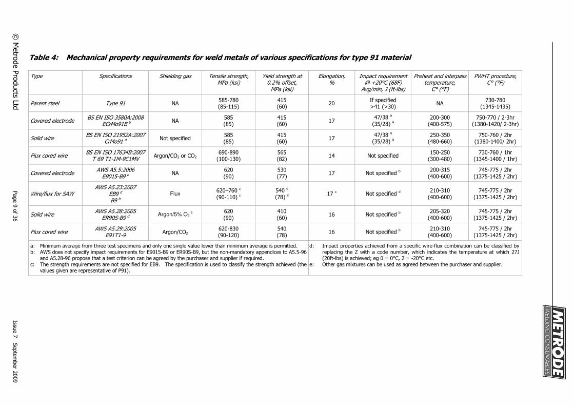
Table 4: Mechanical property requirements for weld metals of various specifications for type 91 material
Type Specifications Shielding gas Tensile strength, MPa (ksi)
Yield strength at 0.2% offset,
MPa (ksi)
Elongation, %
Impact requirement @ +20°C (68F)
Avg/min, J (ft-lbs)
Preheat and interpass temperature,
C° (°F)
PWHT procedure, C° (°F)
Parent steel Type 91 NA
585-780 (85-115)
415 (60)
20 If specified >41 (>30)
NA 730-780
(1345-1435)
Covered electrode
BS EN ISO 3580A:2008 ECrMo91B b
NA 585 (85)
415 (60)
17 47/38
a
(35/28) a
200-300 (400-575)
750-770 / 2-3hr (1380-1420/ 2-3hr)
Solid wire
BS EN ISO 21952A:2007 CrMo91 d
Not specified 585 (85)
415 (60)
17 47/38
a
(35/28) a
250-350 (480-660)
750-760 / 2hr (1380-1400/ 2hr)
Flux cored wire
BS EN ISO 17634B:2007 T 69 T1-1M-9C1MV
Argon/CO2 or CO2 690-890
(100-130) 565 (82)
14 Not specified 150-250
(300-480) 730-760 / 1hr
(1345-1400 / 1hr)
Covered electrode
AWS A5.5:2006 E9015-B9 b
NA 620 (90)
530 (77)
17 Not specified b
200-315 (400-600)
745-775 / 2hr (1375-1425 / 2hr)
Wire/flux for SAW
AWS A5.23:2007 EB9 d B9 b
Flux 620–760 c
(90-110) c
540 c
(78) c
17 c Not specified
d
210-310 (400-600)
745-775 / 2hr (1375-1425 / 2hr)
Solid wire
AWS A5.28:2005 ER90S-B9 d
Argon/5% O2 e
620 (90)
410 (60)
16 Not specified b
205-320 (400-600)
745-775 / 2hr (1375-1425 / 2hr)
Flux cored wire
AWS A5.29:2005 E91T1-9
Argon/CO2 620-830 (90-120)
540 (78)
16 Not specified b
210-310 (400-600)
745-775 / 2hr (1375-1425 / 2hr)
a: Minimum average from three test specimens and only one single value lower than minimum average is permitted. b: AWS does not specify impact requirements for E9015-B9 or ER90S-B9, but the non-mandatory appendices to A5.5-96
and A5.28-96 propose that a test criterion can be agreed by the purchaser and supplier if required. c: The strength requirements are not specified for EB9. The specification is used to classify the strength achieved (the
values given are representative of P91).
d: Impact properties achieved from a specific wire-flux combination can be classified by replacing the Z with a code number, which indicates the temperature at which 27J (20ft-lbs) is achieved; eg 0 = 0°C, 2 = -20°C etc.
e: Other gas mixtures can be used as agreed between the purchaser and supplier.
© M
etro
de
Pro
du
cts Ltd
P
ag
e 9
of 3
6
Issue
7 S
ep
tem
be
r 20
09
© Metrode Products Ltd Page 10 of 36 Issue 7 September 2009
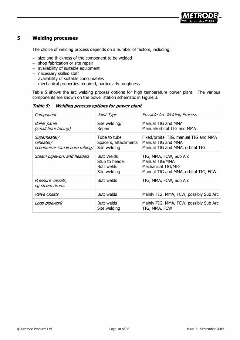
5 Welding processes
The choice of welding process depends on a number of factors, including:
− size and thickness of the component to be welded − shop fabrication or site repair − availability of suitable equipment − necessary skilled staff − availability of suitable consumables − mechanical properties required, particularly toughness
Table 5 shows the arc welding process options for high temperature power plant. The various components are shown on the power station schematic in Figure 3.
Table 5: Welding process options for power plant
Component Joint Type Possible Arc Welding Process
Boiler panel (small bore tubing)
Site welding/ Repair
Manual TIG and MMA Manual/orbital TIG and MMA
Superheater/ reheater/ economiser (small bore tubing)
Tube to tube Spacers, attachments Site welding
Fixed/orbital TIG, manual TIG and MMA Manual TIG and MMA Manual TIG and MMA, orbital TIG
Steam pipework and headers Butt Welds Stub to header Butt welds Site welding
TIG, MMA, FCW, Sub Arc Manual TIG/MMA Mechanical TIG/MIG Manual TIG and MMA, orbital TIG, FCW
Pressure vessels, eg steam drums
Butt welds TIG, MMA, FCW, Sub Arc
Valve Chests Butt welds Mainly TIG, MMA, FCW, possibly Sub Arc
Loop pipework Butt welds Site welding
Mainly TIG, MMA, FCW, possibly Sub Arc TIG, MMA, FCW
© Metrode Products Ltd Page 11 of 36 Issue 7 September 2009
6 Metrode range of welding consumables
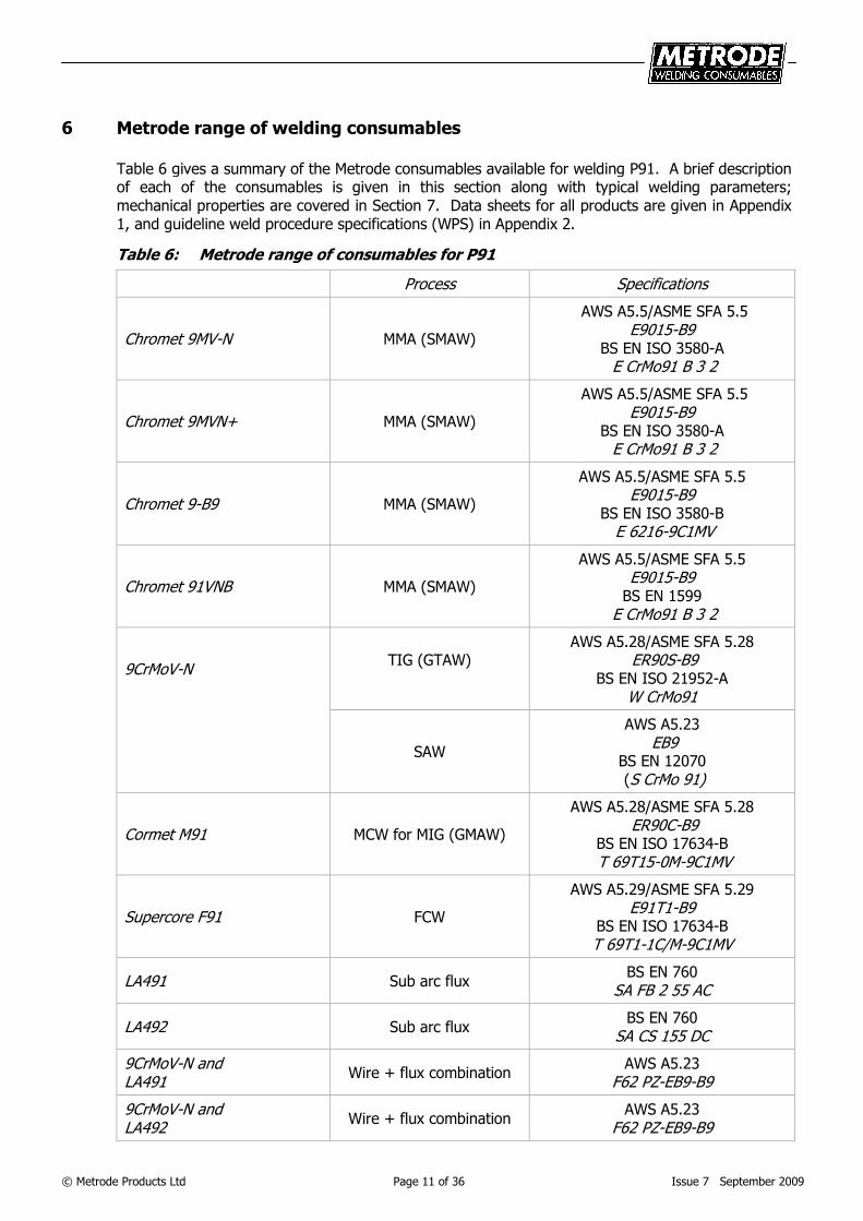
Table 6 gives a summary of the Metrode consumables available for welding P91. A brief description of each of the consumables is given in this section along with typical welding parameters; mechanical properties are covered in Section 7. Data sheets for all products are given in Appendix 1, and guideline weld procedure specifications (WPS) in Appendix 2.
Table 6: Metrode range of consumables for P91
Process Specifications
Chromet 9MV-N MMA (SMAW)
AWS A5.5/ASME SFA 5.5 E9015-B9
BS EN ISO 3580-A E CrMo91 B 3 2
Chromet 9MVN+ MMA (SMAW)
AWS A5.5/ASME SFA 5.5 E9015-B9
BS EN ISO 3580-A E CrMo91 B 3 2
Chromet 9-B9 MMA (SMAW)
AWS A5.5/ASME SFA 5.5 E9015-B9
BS EN ISO 3580-B E 6216-9C1MV
Chromet 91VNB MMA (SMAW)
AWS A5.5/ASME SFA 5.5 E9015-B9
BS EN 1599 E CrMo91 B 3 2
9CrMoV-N
TIG (GTAW)
AWS A5.28/ASME SFA 5.28 ER90S-B9
BS EN ISO 21952-A W CrMo91
SAW
AWS A5.23 EB9
BS EN 12070 (S CrMo 91)
Cormet M91 MCW for MIG (GMAW)
AWS A5.28/ASME SFA 5.28 ER90C-B9
BS EN ISO 17634-B T 69T15-0M-9C1MV
Supercore F91 FCW
AWS A5.29/ASME SFA 5.29 E91T1-B9
BS EN ISO 17634-B T 69T1-1C/M-9C1MV
LA491 Sub arc flux
BS EN 760 SA FB 2 55 AC
LA492 Sub arc flux
BS EN 760 SA CS 155 DC
9CrMoV-N and LA491
Wire + flux combination AWS A5.23
F62 PZ-EB9-B9
9CrMoV-N and LA492
Wire + flux combination AWS A5.23
F62 PZ-EB9-B9
© Metrode Products Ltd Page 12 of 36 Issue 7 September 2009
6.1 MMA (SMAW)
MMA welding is still the most adaptable of the arc welding processes and hence for construction/fabrication work, especially on-site or repair work, is still very widely used. Typical areas of application are shown in Section 5.
As already discussed, P91 materials are fully martensitic under virtually all cooling conditions, and hence as-welded hardnesses are high (~450HV). This means that measures to avoid hydrogen cracking are particularly important. Preheat etc is covered in Section 8, but in relation to MMA electrodes, coating moisture and hence hydrogen potential are critical. To ensure low coating moisture content, the MMA electrodes all have specially designed flux binder systems.
The consumables are packed in hermetically sealed metal tins as defined in AWS A5.5 paragraph 22.2. The as-packed moisture content of the electrode coatings is <0.15%, and the exposed coating moisture (27°C/81°F, 85%RH) as per AWS A5.5 is <0.40%, which means that in AWS/ASME terminology the electrodes can be classified with the H4R suffix.
All of Metrode’s P91 MMA consumables are basic, low hydrogen types with moisture resistant coatings to produce low weld metal hydrogen levels. The consumables all operate DC+ and AC (70 OCV), although DC+ is preferred. The electrodes are all-positional and are suitable for welding fixed pipework in the ASME 5G/6G positions.
There are four Metrode MMA consumables for P91, each with a different typical analysis, see Table 7; but all conforming to ASME IX QW-432 F-Number 4 and QW-442 A-Number 5. The reasons for the different products are briefly explained.
6.1.1 Chromet 9MV-N
This is the standard consumable available and conforms to the BS EN ISO specification, E CrMo91 B, and AWS specification, E9015-B9, Table 3. This product, which contains ~0.7%Ni, would be specified for most standard applications but still meets Ni + Mn of 1.5% maximum. The Chromet 9MV-N electrode has also taken the place of Metrode’s first P91 electrode, Chromet 9MV.
6.1.2 Chromet 9MVN+
This electrode is similar to the Chromet 9MV-N but it is made on a fully matching core wire. Chromet 9MVN+ conforms to the BS EN ISO specification, E CrMo91 B, and the AWS specification, E9015-B9, Table 3.
6.1.3 Chromet 9-B9
This electrode is a derivative of Chromet 9MV-N, originally manufactured for the US market. It is made to conform to the AWS specification, E9015-B9 Table 3, but with additional restrictions on Mn+Ni and hence has been favoured for ASME specified projects. Ni is kept to a maximum of 0.4%.
6.1.4 Chromet 91VNB
This electrode is specifically designed for depositing root runs in single sided open butt joints without gas purging. Chromet 91VNB conforms to AWS E9015-B9 and BS EN ISO E CrMo91 B. To achieve the best root welds joints should be set-up with a root gap of 2.5-4mm (0.10-0.15inch) and root face of 1.5-2.5mm (0.05-0.10inch) and then welded on DC+ at ~75A with a 2.5mm (3/32inch) diameter electrode. For positional joints vertical-up welding is recommended.
© Metrode Products Ltd Page 13 of 36 Issue 7 September 2009
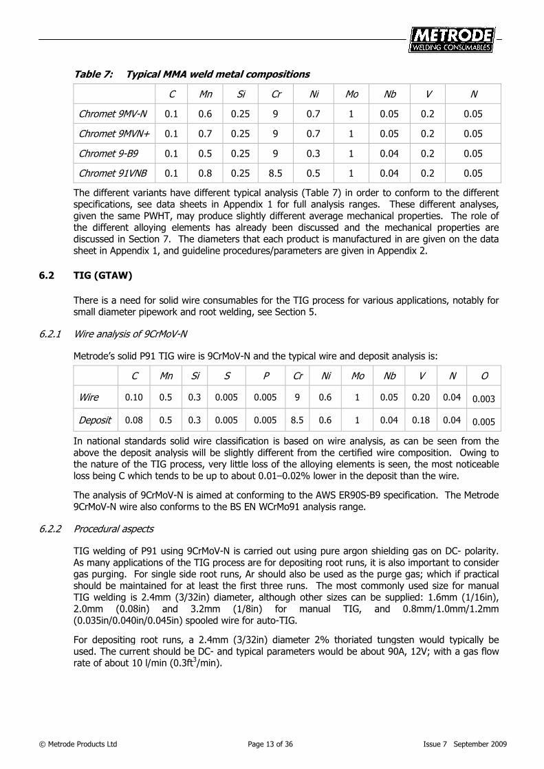
Table 7: Typical MMA weld metal compositions
C Mn Si Cr Ni Mo Nb V N
Chromet 9MV-N 0.1 0.6 0.25 9 0.7 1 0.05 0.2 0.05
Chromet 9MVN+ 0.1 0.7 0.25 9 0.7 1 0.05 0.2 0.05
Chromet 9-B9 0.1 0.5 0.25 9 0.3 1 0.04 0.2 0.05
Chromet 91VNB 0.1 0.8 0.25 8.5 0.5 1 0.04 0.2 0.05
The different variants have different typical analysis (Table 7) in order to conform to the different specifications, see data sheets in Appendix 1 for full analysis ranges. These different analyses, given the same PWHT, may produce slightly different average mechanical properties. The role of the different alloying elements has already been discussed and the mechanical properties are discussed in Section 7. The diameters that each product is manufactured in are given on the data sheet in Appendix 1, and guideline procedures/parameters are given in Appendix 2.
6.2 TIG (GTAW)
There is a need for solid wire consumables for the TIG process for various applications, notably for small diameter pipework and root welding, see Section 5.
6.2.1 Wire analysis of 9CrMoV-N
Metrode’s solid P91 TIG wire is 9CrMoV-N and the typical wire and deposit analysis is:
C Mn Si S P Cr Ni Mo Nb V N O
Wire 0.10 0.5 0.3 0.005 0.005 9 0.6 1 0.05 0.20 0.04 0.003
Deposit 0.08 0.5 0.3 0.005 0.005 8.5 0.6 1 0.04 0.18 0.04 0.005
In national standards solid wire classification is based on wire analysis, as can be seen from the above the deposit analysis will be slightly different from the certified wire composition. Owing to the nature of the TIG process, very little loss of the alloying elements is seen, the most noticeable loss being C which tends to be up to about 0.01–0.02% lower in the deposit than the wire.
The analysis of 9CrMoV-N is aimed at conforming to the AWS ER90S-B9 specification. The Metrode 9CrMoV-N wire also conforms to the BS EN WCrMo91 analysis range.
6.2.2 Procedural aspects
TIG welding of P91 using 9CrMoV-N is carried out using pure argon shielding gas on DC- polarity. As many applications of the TIG process are for depositing root runs, it is also important to consider gas purging. For single side root runs, Ar should also be used as the purge gas; which if practical should be maintained for at least the first three runs. The most commonly used size for manual TIG welding is 2.4mm (3/32in) diameter, although other sizes can be supplied: 1.6mm (1/16in), 2.0mm (0.08in) and 3.2mm (1/8in) for manual TIG, and 0.8mm/1.0mm/1.2mm (0.035in/0.040in/0.045in) spooled wire for auto-TIG.
For depositing root runs, a 2.4mm (3/32in) diameter 2% thoriated tungsten would typically be used. The current should be DC- and typical parameters would be about 90A, 12V; with a gas flow rate of about 10 l/min (0.3ft3/min).
© Metrode Products Ltd Page 14 of 36 Issue 7 September 2009
6.3 MIG (GMAW)
As a process of potentially high productivity, interest in MIG welding of P91 material is increasing. Of the wires available for MIG welding, the metal cored wire (MCW) is proving to be the most attractive owing to its compositional flexibility and lower cost. Metrode’s Cormet M91 MCW, which is available in 1.2mm (0.047in) or 1.6mm (1/16in) diameter, has already found use in a number of applications, including surfacing and casting repair. The use of solid MIG wire is not considered here because experience indicates that the operability of currently available wire is unsatisfactory, owing to typical Mn+Si deoxidant levels which are incompatible with active gas welding.
6.3.1 Shielding gases and weld metal composition for Cormet M91
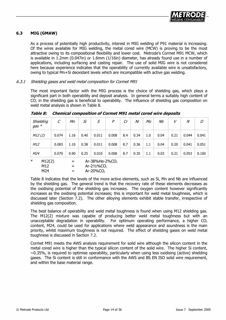
The most important factor with the MIG process is the choice of shielding gas, which plays a significant part in both operability and deposit analysis. In general terms a suitably high content of CO2 in the shielding gas is beneficial to operability. The influence of shielding gas composition on weld metal analysis is shown in Table 8.
Table 8: Chemical composition of Cormet M91 metal cored wire deposits
Shielding gas *
C Mn Si S P Cr Ni Mo Nb V N O
M12 (2) 0.074 1.16 0.40 0.011 0.008 8.4 0.34 1.0 0.04 0.21 0.044 0.041
M12 0.083 1.10 0.38 0.011 0.008 8.7 0.36 1.1 0.04 0.20 0.041 0.051
M24 0.079 0.90 0.25 0.010 0.008 8.7 0.35 1.1 0.03 0.21 0.053 0.100
* M12(2) = Ar-38%He-2%CO2 M12 = Ar-2½%CO2
M24 = Ar-20%CO2
Table 8 indicates that the levels of the more active elements, such as Si, Mn and Nb are influenced by the shielding gas. The general trend is that the recovery rate of these elements decreases as the oxidising potential of the shielding gas increases. The oxygen content however significantly increases as the oxidising potential increases; this is important for weld metal toughness, which is discussed later (Section 7.2). The other alloying elements exhibit stable transfer, irrespective of shielding gas composition.
The best balance of operability and weld metal toughness is found when using M12 shielding gas. The M12(2) mixture was capable of producing better weld metal toughness but with an unacceptable degradation in operability. For optimum operating performance, a higher CO2 content, M24, could be used for applications where weld appearance and soundness is the main priority, whilst maximum toughness is not required. The effect of shielding gases on weld metal toughness is discussed in Section 7.2.
Cormet M91 meets the AWS analysis requirement for solid wire although the silicon content in the metal cored wire is higher than the typical silicon content of the solid wire. The higher Si content, ~0.35%, is required to optimise operability, particularly when using less oxidising (active) shielding gases. The Si content is still in conformance with the AWS and BS EN ISO solid wire requirement, and within the base material range.
© Metrode Products Ltd Page 15 of 36 Issue 7 September 2009
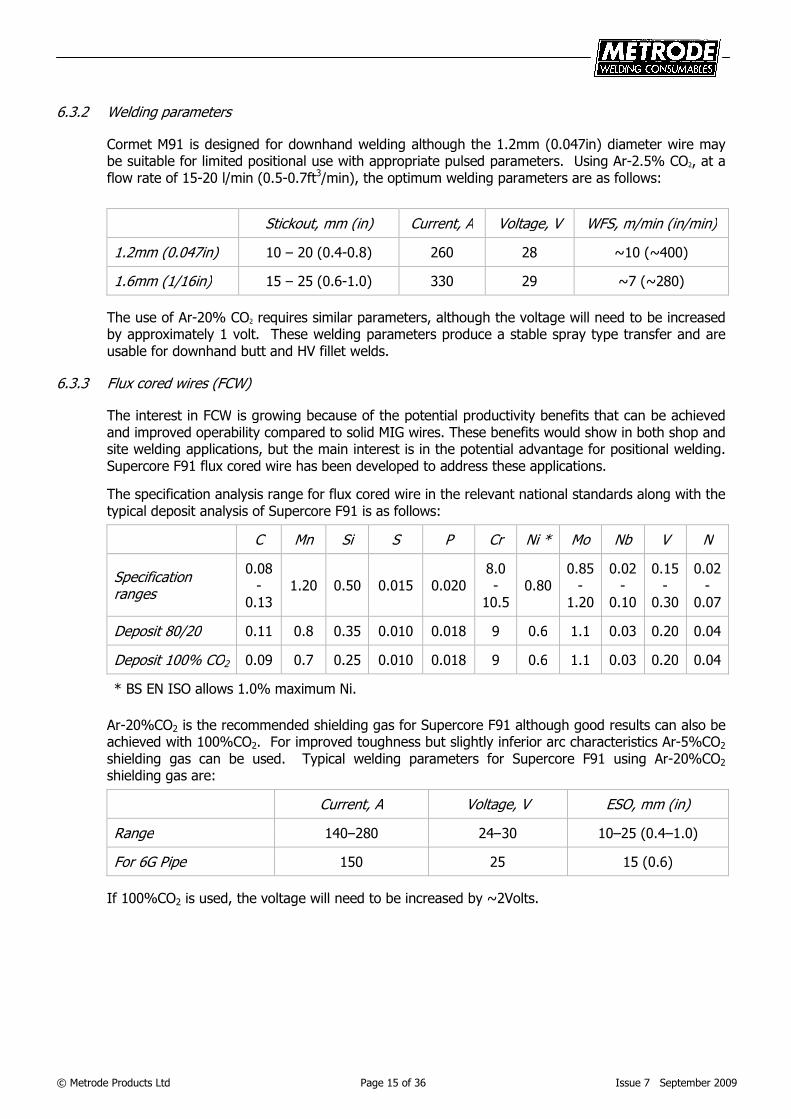
6.3.2 Welding parameters
Cormet M91 is designed for downhand welding although the 1.2mm (0.047in) diameter wire may be suitable for limited positional use with appropriate pulsed parameters. Using Ar-2.5% CO2, at a flow rate of 15-20 l/min (0.5-0.7ft3/min), the optimum welding parameters are as follows:
Stickout, mm (in) Current, A Voltage, V WFS, m/min (in/min)
1.2mm (0.047in) 10 – 20 (0.4-0.8) 260 28 ~10 (~400)
1.6mm (1/16in) 15 – 25 (0.6-1.0) 330 29 ~7 (~280)
The use of Ar-20% CO2 requires similar parameters, although the voltage will need to be increased by approximately 1 volt. These welding parameters produce a stable spray type transfer and are usable for downhand butt and HV fillet welds.
6.3.3 Flux cored wires (FCW)
The interest in FCW is growing because of the potential productivity benefits that can be achieved and improved operability compared to solid MIG wires. These benefits would show in both shop and site welding applications, but the main interest is in the potential advantage for positional welding. Supercore F91 flux cored wire has been developed to address these applications.
The specification analysis range for flux cored wire in the relevant national standards along with the typical deposit analysis of Supercore F91 is as follows:
C Mn Si S P Cr Ni * Mo Nb V N
Specification ranges
0.08-
0.13 1.20 0.50 0.015 0.020
8.0 -
10.5 0.80
0.85-
1.20
0.02 -
0.10
0.15-
0.30
0.02-
0.07
Deposit 80/20 0.11 0.8 0.35 0.010 0.018 9 0.6 1.1 0.03 0.20 0.04
Deposit 100% CO2 0.09 0.7 0.25 0.010 0.018 9 0.6 1.1 0.03 0.20 0.04
* BS EN ISO allows 1.0% maximum Ni.
Ar-20%CO2 is the recommended shielding gas for Supercore F91 although good results can also be achieved with 100%CO2. For improved toughness but slightly inferior arc characteristics Ar-5%CO2 shielding gas can be used. Typical welding parameters for Supercore F91 using Ar-20%CO2 shielding gas are:
Current, A Voltage, V ESO, mm (in)
Range 140–280 24–30 10–25 (0.4–1.0)
For 6G Pipe 150 25 15 (0.6)
If 100%CO2 is used, the voltage will need to be increased by ~2Volts.
© Metrode Products Ltd Page 16 of 36 Issue 7 September 2009
6. 4 Submerged Arc Welding (SAW)
For welding positions and components where mechanised welding is practical, SAW is undoubtedly the preferred and most productive process. To date 2.4mm (3/32in) diameter 9CrMoV-N solid wire is preferred for SAW, although 3.2mm (1/8in) diameter has been used for selected applications.
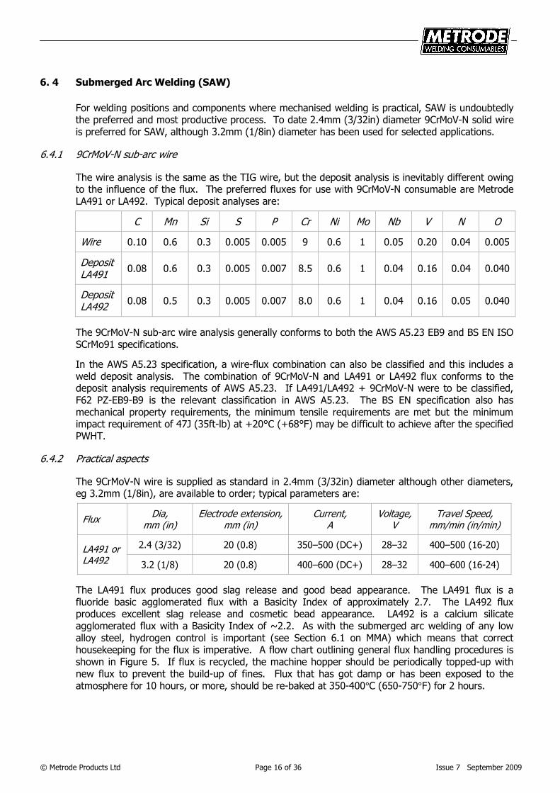
6.4.1 9CrMoV-N sub-arc wire
The wire analysis is the same as the TIG wire, but the deposit analysis is inevitably different owing to the influence of the flux. The preferred fluxes for use with 9CrMoV-N consumable are Metrode LA491 or LA492. Typical deposit analyses are:
C Mn Si S P Cr Ni Mo Nb V N O
Wire 0.10 0.6 0.3 0.005 0.005 9 0.6 1 0.05 0.20 0.04 0.005
Deposit LA491
0.08 0.6 0.3 0.005 0.007 8.5 0.6 1 0.04 0.16 0.04 0.040
Deposit LA492
0.08 0.5 0.3 0.005 0.007 8.0 0.6 1 0.04 0.16 0.05 0.040
The 9CrMoV-N sub-arc wire analysis generally conforms to both the AWS A5.23 EB9 and BS EN ISO SCrMo91 specifications.
In the AWS A5.23 specification, a wire-flux combination can also be classified and this includes a weld deposit analysis. The combination of 9CrMoV-N and LA491 or LA492 flux conforms to the deposit analysis requirements of AWS A5.23. If LA491/LA492 + 9CrMoV-N were to be classified, F62 PZ-EB9-B9 is the relevant classification in AWS A5.23. The BS EN specification also has mechanical property requirements, the minimum tensile requirements are met but the minimum impact requirement of 47J (35ft-lb) at +20°C (+68°F) may be difficult to achieve after the specified PWHT.
6.4.2 Practical aspects
The 9CrMoV-N wire is supplied as standard in 2.4mm (3/32in) diameter although other diameters, eg 3.2mm (1/8in), are available to order; typical parameters are:
Flux
Dia, mm (in)
Electrode extension, mm (in)
Current, A
Voltage, V
Travel Speed, mm/min (in/min)
LA491 or LA492
2.4 (3/32) 20 (0.8) 350–500 (DC+) 28–32 400–500 (16-20)
3.2 (1/8) 20 (0.8) 400–600 (DC+) 28–32 400–600 (16-24)
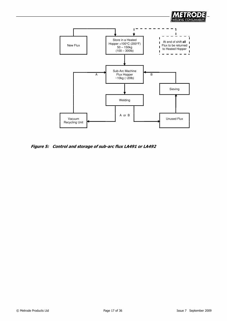
The LA491 flux produces good slag release and good bead appearance. The LA491 flux is a fluoride basic agglomerated flux with a Basicity Index of approximately 2.7. The LA492 flux produces excellent slag release and cosmetic bead appearance. LA492 is a calcium silicate agglomerated flux with a Basicity Index of ~2.2. As with the submerged arc welding of any low alloy steel, hydrogen control is important (see Section 6.1 on MMA) which means that correct housekeeping for the flux is imperative. A flow chart outlining general flux handling procedures is shown in Figure 5. If flux is recycled, the machine hopper should be periodically topped-up with new flux to prevent the build-up of fines. Flux that has got damp or has been exposed to the atmosphere for 10 hours, or more, should be re-baked at 350-400°C (650-750°F) for 2 hours.
© Metrode Products Ltd Page 17 of 36 Issue 7 September 2009
New Flux
Store in a Heated
Hopper >100°C (200°F) 50 – 150kg
(100 – 300lb)
At end of shift all
Flux to be returned to Heated Hopper
A
Sub-Arc Machine
Flux Hopper ~10kg (~20lb)
B
Sieving
Welding
A or B Vacuum
Recycling Unit
Unused Flux
Figure 5: Control and storage of sub-arc flux LA491 or LA492
© Metrode Products Ltd Page 18 of 36 Issue 7 September 2009
7 Mechanical properties
7.1 Room temperature tensile properties
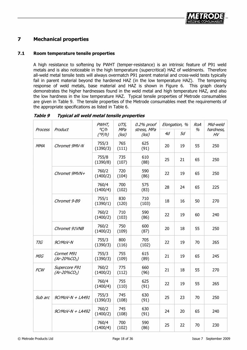
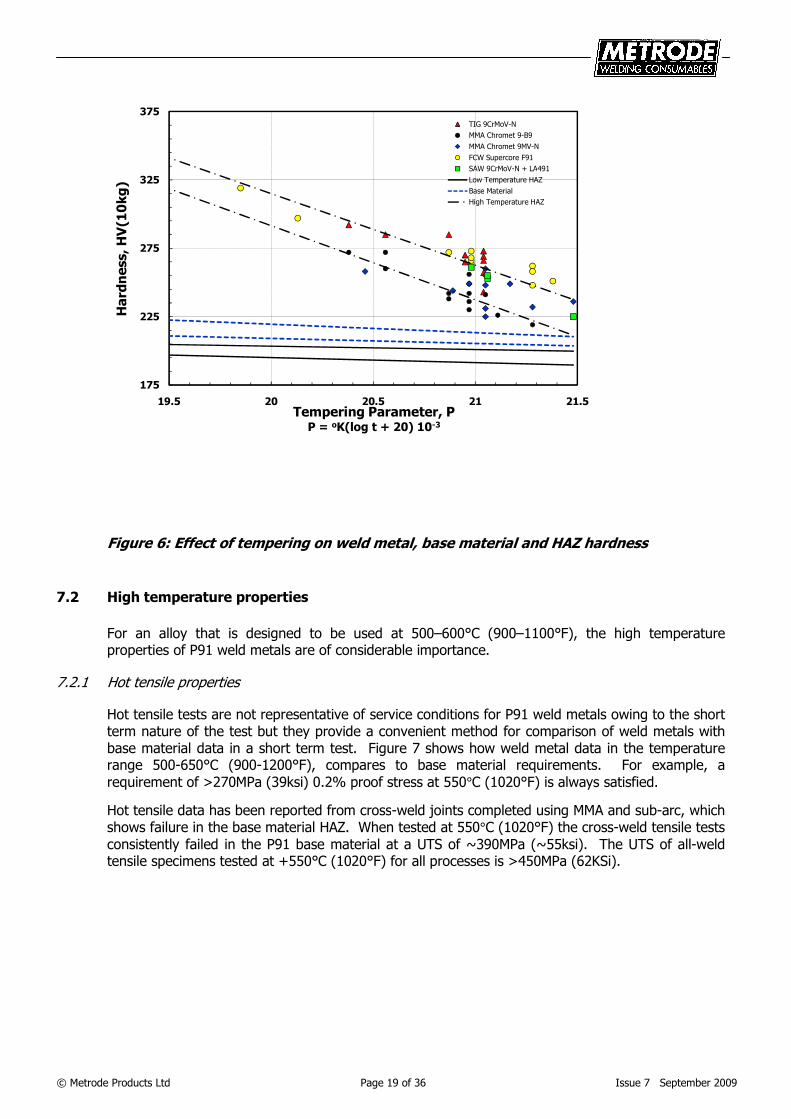
A high resistance to softening by PWHT (temper-resistance) is an intrinsic feature of P91 weld metals and is also noticeable in the high temperature (supercritical) HAZ of weldments. Therefore all-weld metal tensile tests will always overmatch P91 parent material and cross-weld tests typically fail in parent material beyond the hardened HAZ (in the low temperature HAZ). The tempering response of weld metals, base material and HAZ is shown in Figure 6. This graph clearly demonstrates the higher hardnesses found in the weld metal and high temperature HAZ, and also the low hardness in the low temperature HAZ. Typical tensile properties of Metrode consumables are given in Table 9. The tensile properties of the Metrode consumables meet the requirements of the appropriate specifications as listed in Table 6.
Table 9 Typical all weld metal tensile properties
Process Product
PWHT, °C/h
(°F/h)
UTS, MPa (ksi)
0.2% proof stress, MPa
(ksi)
Elongation, % RoA %
Mid-weld hardness,
HV
4d 5d
MMA Chromet 9MV-N
755/3
(1390/3)
765
(111)
625
(91) 20 19 55 250
755/8
(1390/8)
735
(107)
610
(88) 25 21 65 250
Chromet 9MVN+
760/2
(1400/2)
720
(104)
590
(86) 22 19 65 250
760/4
(1400/4)
700
(102)
575
(83) 28 24 65 225
Chromet 9-B9
755/1 (1390/1)
830 (120)
710 (103)
18 16 50 270
760/2 (1400/2)
710 (103)
590 (86)
22 19 60 240
Chromet 91VNB
760/2
(1400/2)
750
(109)
600
(87) 20 18 55 250
TIG 9CrMoV-N
755/3
(1390/3)
800
(116)
705
(102) 22 19 70 265
MIG
Cormet M91 (Ar-20%CO2)
755/3
(1390/3)
755
(109)
615
(89) 21 19 65 245
FCW
Supercore F91 (Ar-20%CO2)
760/2 (1400/2)
775 (112)
660 (96)
21 18 55 270
760/4 (1400/4)
755 (110)
625 (91)
22 19 55 265
Sub arc 9CrMoV-N + LA491
755/3 (1390/3)
745 (108)
630 (91)
25 23 70 250
9CrMoV-N + LA492
760/2
(1400/2)
745
(108)
630
(91) 24 20 65 240
760/4
(1400/4)
700
(102)
590
(86) 25 22 70 230
© Metrode Products Ltd Page 19 of 36 Issue 7 September 2009
175
225
275
325
375
19.5 20 20.5 21 21.5
Hardness, HV(10kg)
Tempering Parameter, PP = oK(log t + 20) 10-3
TIG 9CrMoV-N
MMA Chromet 9-B9
MMA Chromet 9MV-N
FCW Supercore F91
SAW 9CrMoV-N + LA491
Low Temperature HAZ
Base Material
High Temperature HAZ
Figure 6: Effect of tempering on weld metal, base material and HAZ hardness
7.2 High temperature properties
For an alloy that is designed to be used at 500–600°C (900–1100°F), the high temperature properties of P91 weld metals are of considerable importance.
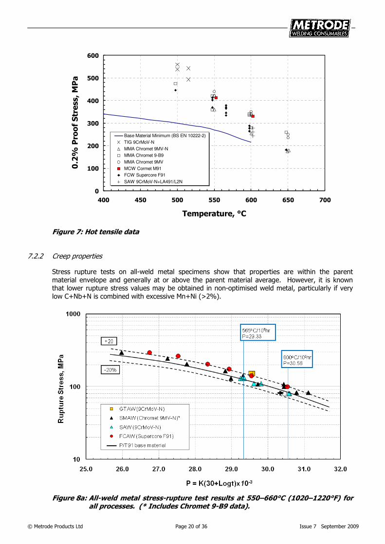
7.2.1 Hot tensile properties
Hot tensile tests are not representative of service conditions for P91 weld metals owing to the short term nature of the test but they provide a convenient method for comparison of weld metals with base material data in a short term test. Figure 7 shows how weld metal data in the temperature range 500-650°C (900-1200°F), compares to base material requirements. For example, a
requirement of >270MPa (39ksi) 0.2% proof stress at 550°C (1020°F) is always satisfied.
Hot tensile data has been reported from cross-weld joints completed using MMA and sub-arc, which shows failure in the base material HAZ. When tested at 550°C (1020°F) the cross-weld tensile tests
consistently failed in the P91 base material at a UTS of ~390MPa (~55ksi). The UTS of all-weld tensile specimens tested at +550°C (1020°F) for all processes is >450MPa (62KSi).
© Metrode Products Ltd Page 20 of 36 Issue 7 September 2009
0
100
200
300
400
500
600
400 450 500 550 600 650 700
Temperature, °C
0.2%
Proof Stress, MPa
Base Material Minimum (BS EN 10222-2)
TIG 9CrMoV-N
MMA Chromet 9MV-N
MMA Chromet 9-B9
MMA Chromet 9MV
MCW Cormet M91
FCW Supercore F91
SAW 9CrMoV-N+LA491/L2N
Figure 7: Hot tensile data
7.2.2 Creep properties
Stress rupture tests on all-weld metal specimens show that properties are within the parent material envelope and generally at or above the parent material average. However, it is known that lower rupture stress values may be obtained in non-optimised weld metal, particularly if very low C+Nb+N is combined with excessive Mn+Ni (>2%).
Figure 8a: All-weld metal stress-rupture test results at 550–660°C (1020–1220°F) for all processes. (* Includes Chromet 9-B9 data).
© Metrode Products Ltd Page 21 of 36 Issue 7 September 2009
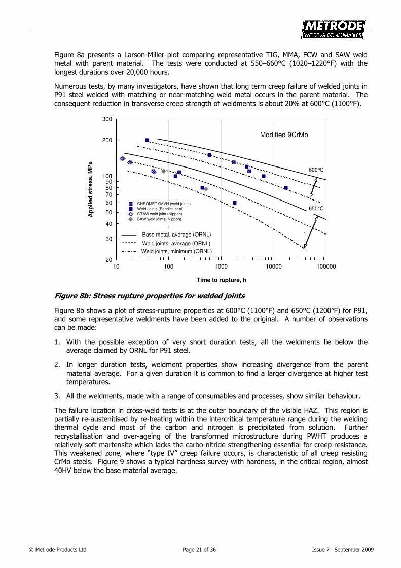
Figure 8a presents a Larson-Miller plot comparing representative TIG, MMA, FCW and SAW weld metal with parent material. The tests were conducted at 550–660°C (1020–1220°F) with the longest durations over 20,000 hours.
Numerous tests, by many investigators, have shown that long term creep failure of welded joints in P91 steel welded with matching or near-matching weld metal occurs in the parent material. The consequent reduction in transverse creep strength of weldments is about 20% at 600°C (1100°F).
10 100 1000 10000 100000
Time to rupture, h
20
30
40
50
60
708090
100
200
300
100
Ap
pli
ed
str
ess
, M
Pa
CHROMET 9MVN (weld joints)
Weld Joints (Bendick et al)
GTAW weld joint (Nippon)
SAW weld joints (Nippon)
Modified 9CrMo
600°C
650°C
Base metal, average (ORNL)
Weld joints, average (ORNL)
Weld joints, minimum (ORNL)
Figure 8b: Stress rupture properties for welded joints
Figure 8b shows a plot of stress-rupture properties at 600°C (1100°F) and 650°C (1200°F) for P91, and some representative weldments have been added to the original. A number of observations can be made:
1. With the possible exception of very short duration tests, all the weldments lie below the average claimed by ORNL for P91 steel.
2. In longer duration tests, weldment properties show increasing divergence from the parent material average. For a given duration it is common to find a larger divergence at higher test temperatures.
3. All the weldments, made with a range of consumables and processes, show similar behaviour.
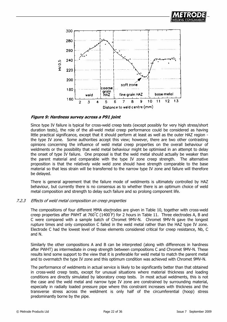
The failure location in cross-weld tests is at the outer boundary of the visible HAZ. This region is partially re-austenitised by re-heating within the intercritical temperature range during the welding thermal cycle and most of the carbon and nitrogen is precipitated from solution. Further recrystallisation and over-ageing of the transformed microstructure during PWHT produces a relatively soft martensite which lacks the carbo-nitride strengthening essential for creep resistance. This weakened zone, where “type IV” creep failure occurs, is characteristic of all creep resisting CrMo steels. Figure 9 shows a typical hardness survey with hardness, in the critical region, almost 40HV below the base material average.
© Metrode Products Ltd Page 22 of 36 Issue 7 September 2009
Figure 9: Hardness survey across a P91 joint
Since type IV failure is typical for cross-weld creep tests (except possibly for very high stress/short duration tests), the role of the all-weld metal creep performance could be considered as having little practical significance, except that it should perform at least as well as the outer HAZ region - the type IV zone. Some authorities accept this view; however, there are two other contrasting opinions concerning the influence of weld metal creep properties on the overall behaviour of weldments or the possibility that weld metal behaviour might be optimised in an attempt to delay the onset of type IV failure. One proposal is that the weld metal should actually be weaker than the parent material and comparable with the type IV zone creep strength. The alternative proposition is that the relatively wide weld zone should have strength comparable to the base material so that less strain will be transferred to the narrow type IV zone and failure will therefore be delayed.
There is general agreement that the failure mode of weldments is ultimately controlled by HAZ behaviour, but currently there is no consensus as to whether there is an optimum choice of weld metal composition and strength to delay such failure and so prolong component life.
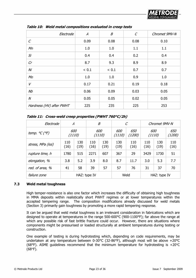
7.2.3 Effects of weld metal composition on creep properties
The compositions of four different MMA electrodes are given in Table 10, together with cross-weld creep properties after PWHT at 760°C (1400°F) for 2 hours in Table 11. Three electrodes A, B and C were compared with a sample batch of Chromet 9MV-N. Chromet 9MV-N gave the longest rupture times and only composition C failed in the weld metal rather than the HAZ type IV zone. Electrode C had the lowest level of those elements considered critical for creep resistance, Nb, C and N.
Similarly the other compositions A and B can be interpreted (along with differences in hardness after PWHT) as intermediate in creep strength between compositions C and Chromet 9MV-N. These results lend some support to the view that it is preferable for weld metal to match the parent metal and to overmatch the type IV zone and this optimum condition was achieved with Chromet 9MV-N.
The performance of weldments in actual service is likely to be significantly better than that obtained in cross-weld creep tests, except for unusual situations where material thickness and loading conditions are directly simulated by laboratory creep tests. In most actual weldments, this is not the case and the weld metal and narrow type IV zone are constrained by surrounding material, especially in radially loaded pressure pipe where this constraint increases with thickness and the transverse stress across the weldment is only half of the circumferential (hoop) stress predominantly borne by the pipe.
© Metrode Products Ltd Page 23 of 36 Issue 7 September 2009
Table 10: Weld metal compositions evaluated in creep tests
Electrode A B C Chromet 9MV-N
C 0.09 0.08 0.08 0.10
Mn 1.0 1.0 1.1 1.1
Si 0.4 0.4 0.2 0.4
Cr 8.7 9.3 8.9 8.9
Ni < 0.1 < 0.1 0.7 0.7
Mo 1.0 1.0 0.9 1.0
V 0.17 0.21 0.19 0.18
Nb 0.06 0.09 0.03 0.05
N 0.05 0.05 0.02 0.05
Hardness (HV) after PWHT 225 235 225 253
Table 11: Cross-weld creep properties (PWHT 760°C/2h)
Electrode A B C Chromet 9MV-N
temp. °C (°F)
600 (1110)
600 (1110)
600 (1110)
650 (1200)
600 (1110)
650 (1200)
stress, MPa (ksi)
110 (16)
130 (19)
110 (16)
130 (19)
130 (19)
110 (16)
110 (16)
130 (19)
110 (16)
rupture time, h 1780 515 2271 607 367 29 3429 1730 51
elongation, % 3.8 5.2 3.9 8.0 8.7 11.7 3.0 5.3 7.7
red. of area, % 41 58 39 57 57 76 31 37 70
failure zone HAZ: type IV Weld HAZ: type IV
7.3 Weld metal toughness
High temper-resistance is also one factor which increases the difficulty of obtaining high toughness in MMA deposits within realistically short PWHT regimes or at lower temperatures within the accepted tempering range. The composition modifications already discussed for weld metals (Section 3) primarily gain toughness by promoting a more rapid tempering response.
It can be argued that weld metal toughness is an irrelevant consideration in fabrications which are designed to operate at temperatures in the range 500-600°C (900-1100°F); far above the range at which any possible risk of fast brittle fracture could occur. However, there are situations where components might be pressurised or loaded structurally at ambient temperatures during testing or construction.
One example of testing is during hydrotesting which, depending on code requirements, may be undertaken at any temperature between 0-30°C (32-86°F), although most will be above +20°C (68°F). ASME guidelines recommend that the minimum temperature for hydrotesting is +20°C
(68°F).
© Metrode Products Ltd Page 24 of 36 Issue 7 September 2009
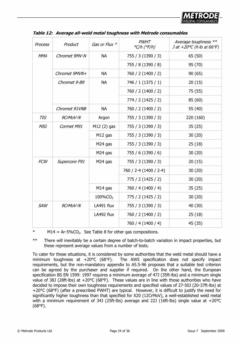
Table 12: Average all-weld metal toughness with Metrode consumables
Process Product Gas or Flux *
PWHT °C/h (°F/h)
Average toughness ** J at +20°C (ft-lb at 68°F)
MMA Chromet 9MV-N NA 755 / 3 (1390 / 3) 65 (50)
755 / 8 (1390 / 8) 95 (70)
Chromet 9MVN+ NA 760 / 2 (1400 / 2) 90 (65)
Chromet 9-B9 NA 746 / 1 (1375 / 1) 20 (15)
760 / 2 (1400 / 2) 75 (55)
774 / 2 (1425 / 2) 85 (60)
Chromet 91VNB NA 760 / 2 (1400 / 2) 55 (40)
TIG 9CrMoV-N Argon 755 / 3 (1390 / 3) 220 (160)
MIG Cormet M91 M12 (2) gas 755 / 3 (1390 / 3) 35 (25)
M12 gas 755 / 3 (1390 / 3) 30 (20)
M24 gas 755 / 3 (1390 / 3) 25 (18)
M24 gas 755 / 6 (1390 / 6) 30 (20)
FCW Supercore F91 M24 gas 755 / 3 (1390 / 3) 20 (15)
760 / 2-4 (1400 / 2-4) 30 (20)
775 / 2 (1425 / 2) 30 (20)
M14 gas 760 / 4 (1400 / 4) 35 (25)
100%CO2 775 / 2 (1425 / 2) 30 (20)
SAW 9CrMoV-N LA491 flux 755 / 3 (1390 / 3) 40 (30)
LA492 flux 760 / 2 (1400 / 2) 25 (18)
760 / 4 (1400 / 4) 45 (35)
* M14 = Ar-5%CO2. See Table 8 for other gas compositions.
** There will inevitably be a certain degree of batch-to-batch variation in impact properties, but these represent average values from a number of tests.
To cater for these situations, it is considered by some authorities that the weld metal should have a
minimum toughness at +20°C (68°F). The AWS specification does not specify impact requirements, but the non-mandatory appendix to A5.5-96 proposes that a suitable test criterion can be agreed by the purchaser and supplier if required. On the other hand, the European specification BS EN 1599: 1997 requires a minimum average of 47J (35ft-lbs) and a minimum single value of 38J (28ft-lbs) at +20°C (68°F). These values are in line with those authorities who have decided to impose their own toughness requirements and specified values of 27-50J (20-37ft-lbs) at +20°C (68°F) (after a prescribed PWHT) are typical. However, it is difficult to justify the need for significantly higher toughness than that specified for X20 (12CrMoV), a well-established weld metal with a minimum requirement of 34J (25ft-lbs) average and 22J (16ft-lbs) single value at +20°C (68°F).
© Metrode Products Ltd Page 25 of 36 Issue 7 September 2009
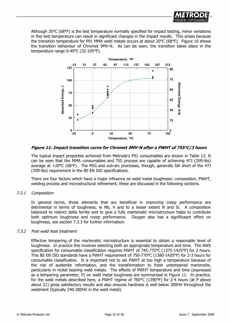
Although 20°C (68°F) is the test temperature normally specified for impact testing, minor variations in this test temperature can result in significant changes in the impact results. This arises because the transition temperature for P91 MMA weld metals occurs at about 20°C (68°F). Figure 10 shows the transition behaviour of Chromet 9MV-N. As can be seen, the transition takes place in the temperature range 0-40°C (32-105°F).
-25 0 25 50 75 100
Temperature, oC
0
25
50
75
100
125
Ab
so
rbe
d E
ne
rgy
, J
-13 12 37 62 87 112 137 162 187 212
Temperature, oF
0
15
30
45
60
75
90
Ab
so
rbed
En
erg
y, ft-lb
Figure 11: Impact transition curve for Chromet 9MV-N after a PWHT of 755°°°°C/3 hours
The typical impact properties achieved from Metrode’s P91 consumables are shown in Table 12. It can be seen that the MMA consumables and TIG process are capable of achieving 47J (35ft-lbs)
average at +20°C (68°F). The MIG and sub-arc processes, though, generally fall short of the 47J (35ft-lbs) requirement in the BS EN ISO specifications.
There are four factors which have a major influence on weld metal toughness: composition, PWHT, welding process and microstructural refinement; these are discussed in the following sections.
7.3.1 Composition
In general terms, those elements that are beneficial in improving creep performance are detrimental in terms of toughness, ie Nb, V and to a lesser extent N and Si. A composition balanced to restrict delta ferrite and to give a fully martensitic microstructure helps to contribute both optimum toughness and creep performance. Oxygen also has a significaqnt effect on toughness, see section 7.3.3 for further information.
7.3.2 Post weld heat treatment
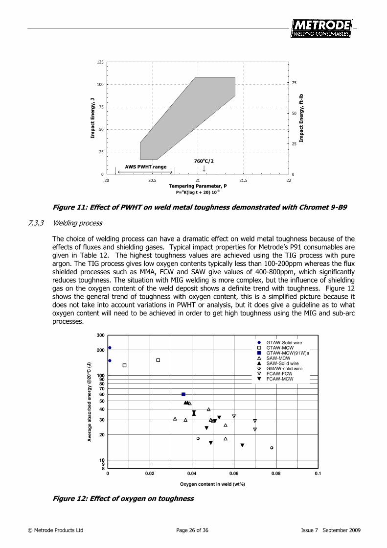
Effective tempering of the martensitic microstructure is essential to obtain a reasonable level of toughness. In practice this involves selecting both an appropriate temperature and time. The AWS specification for consumable classification requires PWHT of 745-775°C (1375-1425°F) for 2 hours. This BS EN ISO standards have a PWHT requirement of 750-770°C (1380-1420°F) for 2-3 hours for consumable classification. It is important not to set PWHT at too high a temperature because of the risk of austenite reformation, and the transformation to fresh untempered martensite, particularly in nickel bearing weld metals. The effects of PWHT temperature and time (expressed as a tempering parameter, P) on weld metal toughness are summarised in Figure 11. In practice, for the weld metals described here, a PWHT regime of 760°C (1390°F) for 2-4 hours (at P above about 21) gives satisfactory results and also ensures hardness is well below 300HV throughout the weldment (typically 240-280HV in the weld metal).
© Metrode Products Ltd Page 26 of 36 Issue 7 September 2009
0
25
50
75
100
125
20 20.5 21 21.5 22
Tempering Parameter, P
P=oK(log t + 20) 10
-3
Impact Energy, J
0
25
50
75
Impact Energy, ft-lb
AWS PWHT range
760oC/2
hours
Figure 11: Effect of PWHT on weld metal toughness demonstrated with Chromet 9-B9
7.3.3 Welding process
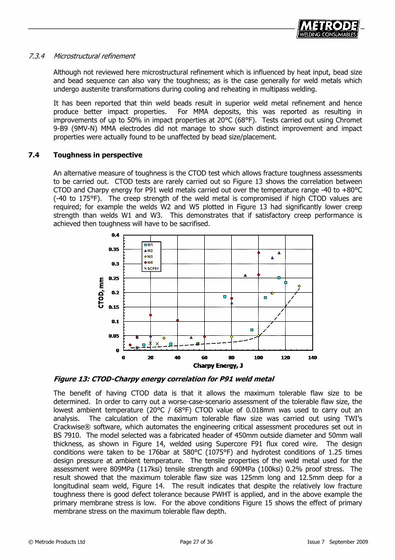
The choice of welding process can have a dramatic effect on weld metal toughness because of the effects of fluxes and shielding gases. Typical impact properties for Metrode’s P91 consumables are given in Table 12. The highest toughness values are achieved using the TIG process with pure argon. The TIG process gives low oxygen contents typically less than 100-200ppm whereas the flux shielded processes such as MMA, FCW and SAW give values of 400-800ppm, which significantly reduces toughness. The situation with MIG welding is more complex, but the influence of shielding gas on the oxygen content of the weld deposit shows a definite trend with toughness. Figure 12 shows the general trend of toughness with oxygen content, this is a simplified picture because it does not take into account variations in PWHT or analysis, but it does give a guideline as to what oxygen content will need to be achieved in order to get high toughness using the MIG and sub-arc processes.
0 0.02 0.04 0.06 0.08 0.1
Oxygen content in weld (wt%)
89
10
20
30
40
50
60
708090
100
200
300
10
100
Ave
rag
e a
bso
rbe
d e
ne
rgy
@2
0°C
(J)
GTAW-Solid wireGTAW-MCWGTAW-MCW(91W)aSAW-MCWSAW-Solid wireGMAW-solid wireFCAW-FCW*FCAW-MCW
Figure 12: Effect of oxygen on toughness
© Metrode Products Ltd Page 27 of 36 Issue 7 September 2009
7.3.4 Microstructural refinement
Although not reviewed here microstructural refinement which is influenced by heat input, bead size and bead sequence can also vary the toughness; as is the case generally for weld metals which undergo austenite transformations during cooling and reheating in multipass welding.
It has been reported that thin weld beads result in superior weld metal refinement and hence produce better impact properties. For MMA deposits, this was reported as resulting in improvements of up to 50% in impact properties at 20°C (68°F). Tests carried out using Chromet 9-B9 (9MV-N) MMA electrodes did not manage to show such distinct improvement and impact properties were actually found to be unaffected by bead size/placement.
7.4 Toughness in perspective
An alternative measure of toughness is the CTOD test which allows fracture toughness assessments to be carried out. CTOD tests are rarely carried out so Figure 13 shows the correlation between CTOD and Charpy energy for P91 weld metals carried out over the temperature range -40 to +80°C (-40 to 175°F). The creep strength of the weld metal is compromised if high CTOD values are required; for example the welds W2 and W5 plotted in Figure 13 had significantly lower creep strength than welds W1 and W3. This demonstrates that if satisfactory creep performance is achieved then toughness will have to be sacrifised.
Figure 13: CTOD-Charpy energy correlation for P91 weld metal
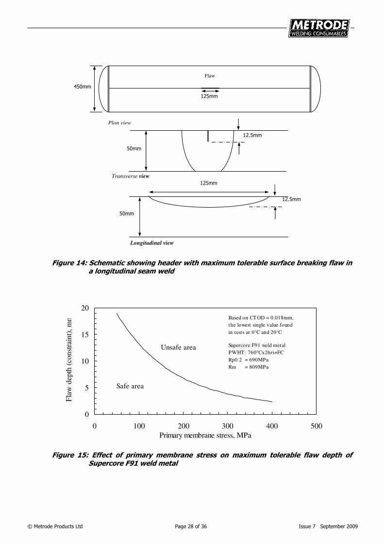
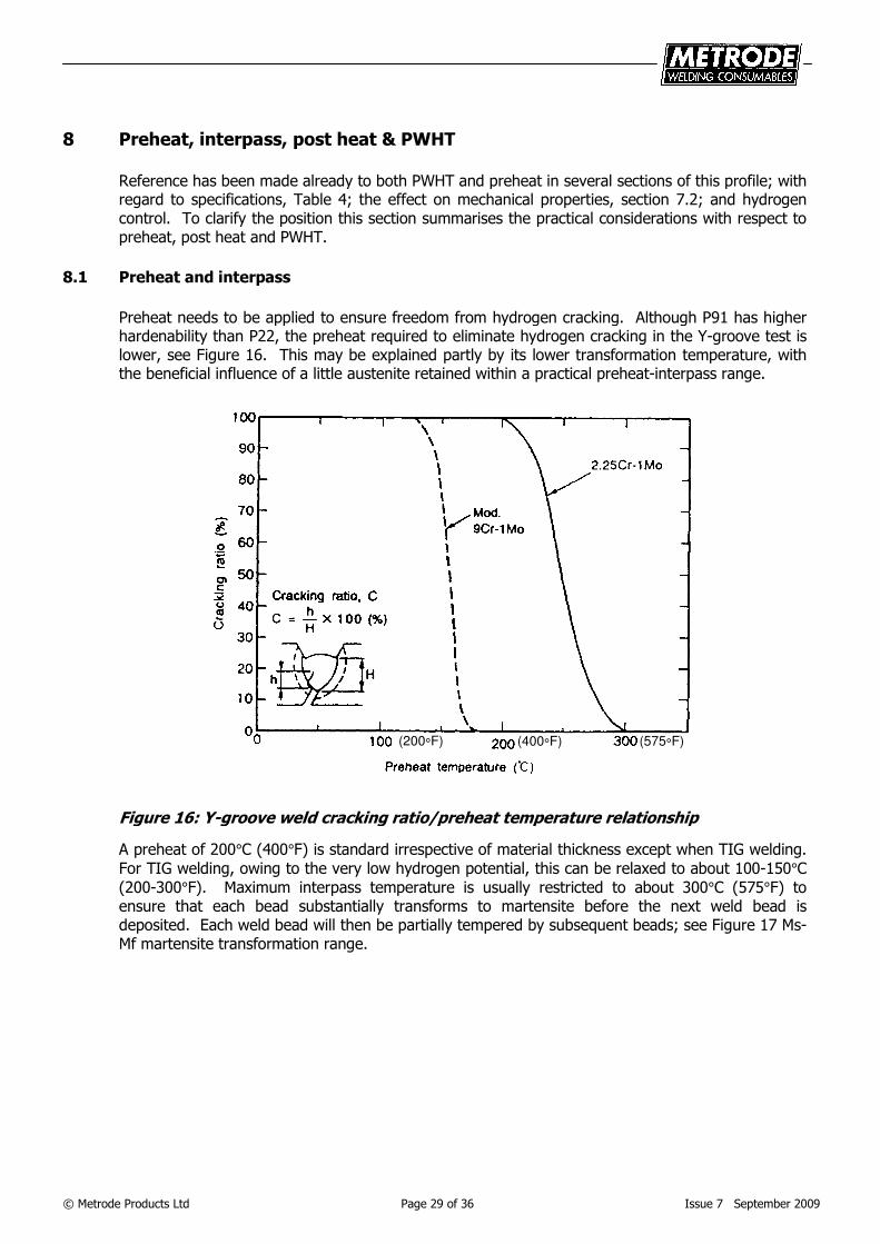
The benefit of having CTOD data is that it allows the maximum tolerable flaw size to be determined. In order to carry out a worse-case-scenario assessment of the tolerable flaw size, the lowest ambient temperature (20°C / 68°F) CTOD value of 0.018mm was used to carry out an analysis. The calculation of the maximum tolerable flaw size was carried out using TWI’s Crackwise® software, which automates the engineering critical assessment procedures set out in BS 7910. The model selected was a fabricated header of 450mm outside diameter and 50mm wall thickness, as shown in Figure 14, welded using Supercore F91 flux cored wire. The design conditions were taken to be 176bar at 580°C (1075°F) and hydrotest conditions of 1.25 times design pressure at ambient temperature. The tensile properties of the weld metal used for the assessment were 809MPa (117ksi) tensile strength and 690MPa (100ksi) 0.2% proof stress. The result showed that the maximum tolerable flaw size was 125mm long and 12.5mm deep for a longitudinal seam weld, Figure 14. The result indicates that despite the relatively low fracture toughness there is good defect tolerance because PWHT is applied, and in the above example the primary membrane stress is low. For the above conditions Figure 15 shows the effect of primary membrane stress on the maximum tolerable flaw depth.
© Metrode Products Ltd Page 28 of 36 Issue 7 September 2009
Figure 14: Schematic showing header with maximum tolerable surface breaking flaw in a longitudinal seam weld
0
5
10
15
20
0 100 200 300 400 500
Primary membrane stress, MPa
Fla
w d
epth
(co
nst
rain
t), m
m
Supercore F91 weld metal
PWHT: 760°Cx2hrs+FC
Rp0.2 = 690MPa
Rm = 809MPa
Based on CTOD = 0.018mm,
the lowest single value found
in tests at 0°C and 20°C
Safe area
Unsafe area
Figure 15: Effect of primary membrane stress on maximum tolerable flaw depth of Supercore F91 weld metal
450mm
125mm
12.5mm
Flaw
125mm
Plan view
Transverse view
Longitudinal view
12.5mm
50mm
50mm
© Metrode Products Ltd Page 29 of 36 Issue 7 September 2009
8 Preheat, interpass, post heat & PWHT
Reference has been made already to both PWHT and preheat in several sections of this profile; with regard to specifications, Table 4; the effect on mechanical properties, section 7.2; and hydrogen control. To clarify the position this section summarises the practical considerations with respect to preheat, post heat and PWHT.
8.1 Preheat and interpass
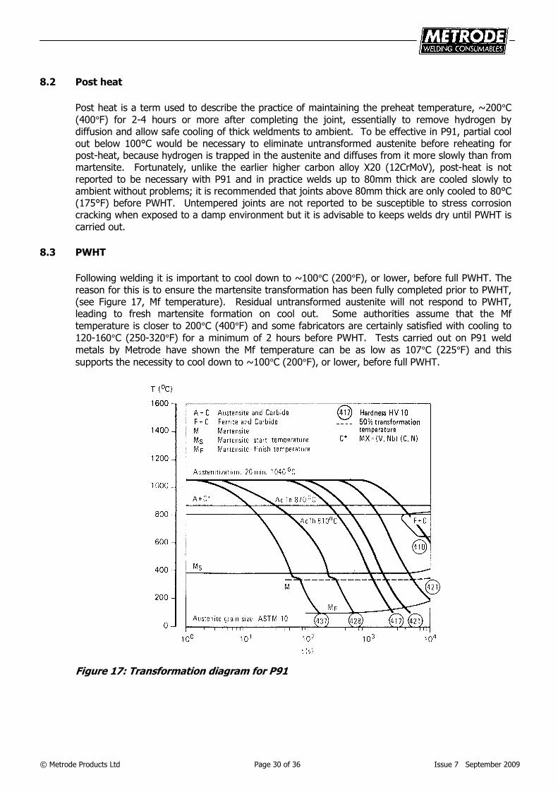
Preheat needs to be applied to ensure freedom from hydrogen cracking. Although P91 has higher hardenability than P22, the preheat required to eliminate hydrogen cracking in the Y-groove test is lower, see Figure 16. This may be explained partly by its lower transformation temperature, with the beneficial influence of a little austenite retained within a practical preheat-interpass range.
(575°F)(400°F)(200°F)
Figure 16: Y-groove weld cracking ratio/preheat temperature relationship
A preheat of 200°C (400°F) is standard irrespective of material thickness except when TIG welding.
For TIG welding, owing to the very low hydrogen potential, this can be relaxed to about 100-150°C
(200-300°F). Maximum interpass temperature is usually restricted to about 300°C (575°F) to ensure that each bead substantially transforms to martensite before the next weld bead is deposited. Each weld bead will then be partially tempered by subsequent beads; see Figure 17 Ms-Mf martensite transformation range.
© Metrode Products Ltd Page 30 of 36 Issue 7 September 2009
8.2 Post heat
Post heat is a term used to describe the practice of maintaining the preheat temperature, ~200°C
(400°F) for 2-4 hours or more after completing the joint, essentially to remove hydrogen by diffusion and allow safe cooling of thick weldments to ambient. To be effective in P91, partial cool out below 100°C would be necessary to eliminate untransformed austenite before reheating for post-heat, because hydrogen is trapped in the austenite and diffuses from it more slowly than from martensite. Fortunately, unlike the earlier higher carbon alloy X20 (12CrMoV), post-heat is not reported to be necessary with P91 and in practice welds up to 80mm thick are cooled slowly to ambient without problems; it is recommended that joints above 80mm thick are only cooled to 80°C (175°F) before PWHT. Untempered joints are not reported to be susceptible to stress corrosion cracking when exposed to a damp environment but it is advisable to keeps welds dry until PWHT is carried out.
8.3 PWHT
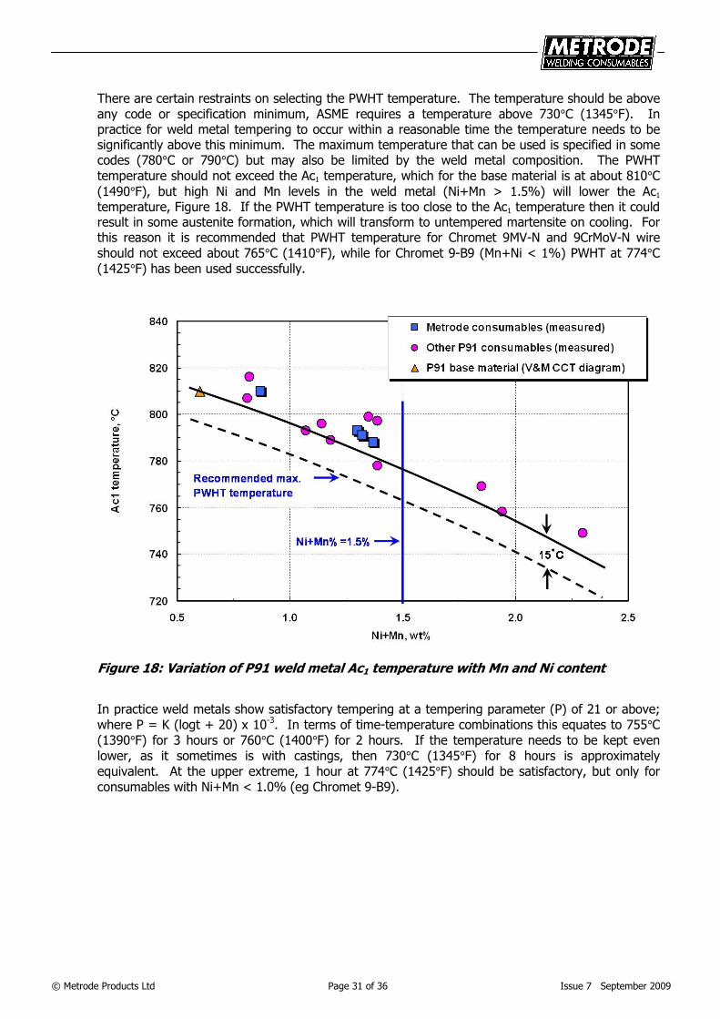
Following welding it is important to cool down to ~100°C (200°F), or lower, before full PWHT. The reason for this is to ensure the martensite transformation has been fully completed prior to PWHT, (see Figure 17, Mf temperature). Residual untransformed austenite will not respond to PWHT, leading to fresh martensite formation on cool out. Some authorities assume that the Mf
temperature is closer to 200°C (400°F) and some fabricators are certainly satisfied with cooling to
120-160°C (250-320°F) for a minimum of 2 hours before PWHT. Tests carried out on P91 weld
metals by Metrode have shown the Mf temperature can be as low as 107°C (225°F) and this
supports the necessity to cool down to ~100°C (200°F), or lower, before full PWHT.
Figure 17: Transformation diagram for P91
© Metrode Products Ltd Page 31 of 36 Issue 7 September 2009
There are certain restraints on selecting the PWHT temperature. The temperature should be above
any code or specification minimum, ASME requires a temperature above 730°C (1345°F). In practice for weld metal tempering to occur within a reasonable time the temperature needs to be significantly above this minimum. The maximum temperature that can be used is specified in some codes (780°C or 790°C) but may also be limited by the weld metal composition. The PWHT
temperature should not exceed the Ac1 temperature, which for the base material is at about 810°C
(1490°F), but high Ni and Mn levels in the weld metal (Ni+Mn > 1.5%) will lower the Ac1 temperature, Figure 18. If the PWHT temperature is too close to the Ac1 temperature then it could result in some austenite formation, which will transform to untempered martensite on cooling. For this reason it is recommended that PWHT temperature for Chromet 9MV-N and 9CrMoV-N wire
should not exceed about 765°C (1410°F), while for Chromet 9-B9 (Mn+Ni < 1%) PWHT at 774°C
(1425°F) has been used successfully.
Figure 18: Variation of P91 weld metal Ac1 temperature with Mn and Ni content
In practice weld metals show satisfactory tempering at a tempering parameter (P) of 21 or above;
where P = K (logt + 20) x 10-3. In terms of time-temperature combinations this equates to 755°C
(1390°F) for 3 hours or 760°C (1400°F) for 2 hours. If the temperature needs to be kept even
lower, as it sometimes is with castings, then 730°C (1345°F) for 8 hours is approximately
equivalent. At the upper extreme, 1 hour at 774°C (1425°F) should be satisfactory, but only for
consumables with Ni+Mn < 1.0% (eg Chromet 9-B9).
© Metrode Products Ltd Page 32 of 36 Issue 7 September 2009
9 Welding P91 to dissimilar materials
The use of P91 is logically applied where its combination of properties are most appropriate, so it is inevitable that joints with dissimilar creep-resisting steels are often necessary. These are usually of lower alloy ferritic types such as P22 (2CrMo) or one of the lean CrMoV alloys. Occasionally joints may be needed between P91 and one of the austenitic stainless heat resisting steels such as 316H. The joining of P91 to ferritic and austenitic alloys requires consideration separately
9.1 P91 to P22 or other low alloy steels
Although P91 has been used over a significant period of time in construction involving welds to dissimilar materials, it is surprising that in practice there is no universally accepted recommendation for a particular weld metal composition and procedure. Two specifications, which offer relevant guidance for welding dissimilar creep resisting steels, are AWS D10.8 and BS 2633. In AWS D10.8 the four possible options for weld metal composition are listed; these are (1) matching the lower alloy, 2CrMo, (2) matching the higher alloy, P91, (3) an intermediate composition, possibly 5CrMo or 9CrMo, (4) different to any of these, in practice a nickel base alloy. Preference is given to the lower alloy option, on the grounds that it should be sufficient to match the weaker of the two materials being joined. A similar approach is presented in BS 2633 except that the intermediate type 9CrMo is suggested for dissimilar joints involving P91. Greater emphasis is also given, in BS 2633, to considering a nickel base weld metal, whereas in AWS D10.8 this approach is considered unnecessary except where stainless steel or nickel alloy base materials are involved. The use of nickel base also limits the scope for NDT methods.
It is also important to consider the most appropriate PWHT regime to reconcile the different
optimum ranges for P91 730-790°C (1345-1455°F), P22 680-720°C (1255-1330°F), and the weld metal. BS 2633 explains that the PWHT temperature is a compromise and in general is applied at the lowest temperature for the higher alloy material, although for optimum creep properties the highest temperature allowed for the lower alloy material should be used. Hence a temperature
around 720-730°C (1330-1345°F), for 1-3 hours, is frequently reported. This is sufficient to temper the P91 HAZ without over-tempering the P22, and is also a satisfactory temperature for welds using either 2CrMo or 9CrMo consumables. However, it is too low for satisfactory tempering if the weld
metal is a P91 type, for which 746°C (1375°F) has been reported for dissimilar joints; >2 hours or ~½ hour for small bore pipe <10mm (<0.4in) wall thickness.
PWHT is of course necessary for stress relief and to give the weldment satisfactory ductility and toughness. However, there is a tendency for PWHT (and long term service at operating temperature) to promote carbon migration around fusion boundaries towards the higher chromium alloy. Consequently a weakened carbon-depleted zone develops in the adjacent material with lower chromium, which may be located in the weld metal or base material, depending on weld metal composition. If this process is not too severe, ultimate failure is expected in the lower alloy base material (eg P22 type IV zone). It seems that the weld metal composition preferred by different authorities is influenced by their assessment of these issues.
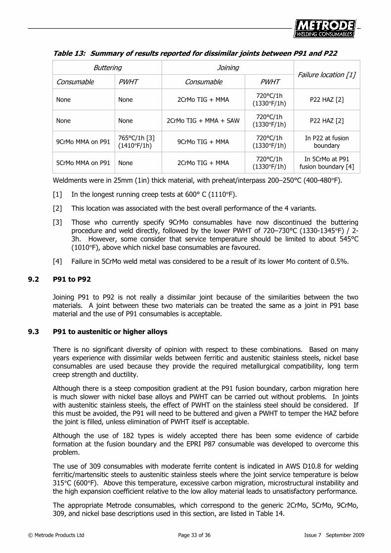
In summary the results of some recently reported tests are given in Table 13. The evidence of these tests indicates that 2CrMo consumables are capable of providing satisfactory performance, which supports a number of authorities and the recommendation given in AWS D10.8.
The use of 2CrMo is also consistent with procedures used by some fabricators who firstly butter the
P91 with 2CrMo and PWHT at ~760°C (~1400°F). The joint is then made between the P22 and
buttered P91 using 2CrMo consumables followed by a 720°C (1330°F) PWHT. This procedure has overcome the need for field joints between two dissimilar materials by allowing a joint between P22 and 2CrMo buttering to be carried out on site.
In summary a direct joint using 2CrMo consumables and PWHT of ~730°C has proved satisfactory.
© Metrode Products Ltd Page 33 of 36 Issue 7 September 2009
Table 13: Summary of results reported for dissimilar joints between P91 and P22
Buttering Joining Failure location [1]
Consumable PWHT Consumable PWHT
None None 2CrMo TIG + MMA
720°C/1h
(1330°F/1h) P22 HAZ [2]
None None 2CrMo TIG + MMA + SAW
720°C/1h (1330°F/1h)
P22 HAZ [2]
9CrMo MMA on P91
765°C/1h [3]
(1410°F/1h) 9CrMo TIG + MMA
720°C/1h
(1330°F/1h) In P22 at fusion
boundary
5CrMo MMA on P91 None 2CrMo TIG + MMA
720°C/1h (1330°F/1h)
In 5CrMo at P91
fusion boundary [4]
Weldments were in 25mm (1in) thick material, with preheat/interpass 200–250°C (400-480°F).
[1] In the longest running creep tests at 600° C (1110°F).
[2] This location was associated with the best overall performance of the 4 variants.
[3] Those who currently specify 9CrMo consumables have now discontinued the buttering procedure and weld directly, followed by the lower PWHT of 720–730°C (1330-1345°F) / 2-3h. However, some consider that service temperature should be limited to about 545°C
(1010°F), above which nickel base consumables are favoured.
[4] Failure in 5CrMo weld metal was considered to be a result of its lower Mo content of 0.5%.
9.2 P91 to P92
Joining P91 to P92 is not really a dissimilar joint because of the similarities between the two materials. A joint between these two materials can be treated the same as a joint in P91 base material and the use of P91 consumables is acceptable.
9.3 P91 to austenitic or higher alloys
There is no significant diversity of opinion with respect to these combinations. Based on many years experience with dissimilar welds between ferritic and austenitic stainless steels, nickel base consumables are used because they provide the required metallurgical compatibility, long term creep strength and ductility.
Although there is a steep composition gradient at the P91 fusion boundary, carbon migration here is much slower with nickel base alloys and PWHT can be carried out without problems. In joints with austenitic stainless steels, the effect of PWHT on the stainless steel should be considered. If this must be avoided, the P91 will need to be buttered and given a PWHT to temper the HAZ before the joint is filled, unless elimination of PWHT itself is acceptable.
Although the use of 182 types is widely accepted there has been some evidence of carbide formation at the fusion boundary and the EPRI P87 consumable was developed to overcome this problem.
The use of 309 consumables with moderate ferrite content is indicated in AWS D10.8 for welding ferritic/martensitic steels to austenitic stainless steels where the joint service temperature is below 315°C (600°F). Above this temperature, excessive carbon migration, microstructural instability and the high expansion coefficient relative to the low alloy material leads to unsatisfactory performance.
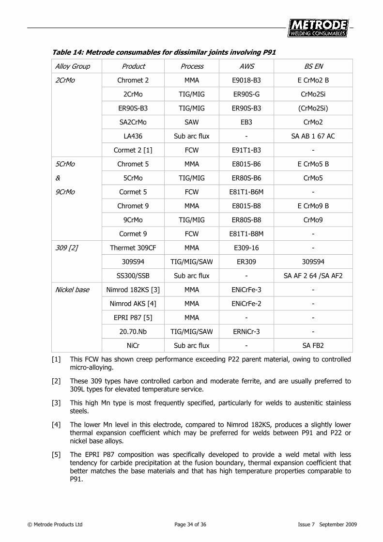
The appropriate Metrode consumables, which correspond to the generic 2CrMo, 5CrMo, 9CrMo, 309, and nickel base descriptions used in this section, are listed in Table 14.
© Metrode Products Ltd Page 34 of 36 Issue 7 September 2009
Table 14: Metrode consumables for dissimilar joints involving P91
Alloy Group Product Process AWS BS EN
2CrMo Chromet 2 MMA E9018-B3 E CrMo2 B
2CrMo TIG/MIG ER90S-G CrMo2Si
ER90S-B3 TIG/MIG ER90S-B3 (CrMo2Si)
SA2CrMo SAW EB3 CrMo2
LA436 Sub arc flux - SA AB 1 67 AC
Cormet 2 [1] FCW E91T1-B3 -
5CrMo Chromet 5 MMA E8015-B6 E CrMo5 B
& 5CrMo TIG/MIG ER80S-B6 CrMo5
9CrMo Cormet 5 FCW E81T1-B6M -
Chromet 9 MMA E8015-B8 E CrMo9 B
9CrMo TIG/MIG ER80S-B8 CrMo9
Cormet 9 FCW E81T1-B8M -
309 [2] Thermet 309CF MMA E309-16 -
309S94 TIG/MIG/SAW ER309 309S94
SS300/SSB Sub arc flux - SA AF 2 64 /SA AF2
Nickel base Nimrod 182KS [3] MMA ENiCrFe-3 -
Nimrod AKS [4] MMA ENiCrFe-2 -
EPRI P87 [5] MMA - -
20.70.Nb TIG/MIG/SAW ERNiCr-3 -
NiCr Sub arc flux - SA FB2
[1] This FCW has shown creep performance exceeding P22 parent material, owing to controlled micro-alloying.
[2] These 309 types have controlled carbon and moderate ferrite, and are usually preferred to 309L types for elevated temperature service.
[3] This high Mn type is most frequently specified, particularly for welds to austenitic stainless steels.
[4] The lower Mn level in this electrode, compared to Nimrod 182KS, produces a slightly lower thermal expansion coefficient which may be preferred for welds between P91 and P22 or nickel base alloys.
[5] The EPRI P87 composition was specifically developed to provide a weld metal with less tendency for carbide precipitation at the fusion boundary, thermal expansion coefficient that better matches the base materials and that has high temperature properties comparable to P91.
© Metrode Products Ltd Page 35 of 36 Issue 7 September 2009
10 Future developments
The commercial application of P91 is now well established but the development of this alloy system has continued with further improvements in performance. In the new modified steels (eg. P92) creep strength is increased by adding tungsten to raise the Mo-equivalent (Mo + 0.5W) from 1% to about 1.5% in a matrix composition essentially similar to P91.
Two new advanced steels of this type are now commercially available. The first originated in Japan as Nippon NF616 and following an EPRI project became the basis for ASME type P92, with 0.5%Mo-1.8%W. The second alloy, E911 (ASME type P911) has 1%Mo-1%W and was developed within the European COST 501 collaborative project. Welding procedures for these materials are essentially similar to those applied to P91. Welding consumables are close to matching base material but generally require a small addition of nickel to optimise toughness. As with P91, the creep performance of welded joints is controlled by type IV failure in the base material HAZ, but with an overall enhancement in rupture stress. The P92 alloy is now being specified and there is a Metrode Technical Profile available covering consumables for P92.
There is also now another new alloy that has been developed as part of the COST 536 collaborative project called CB2 (casting) or FB2 (forging). Development of a pipe material is currently being undertaken. The alloy is based on a 9%Cr alloy but with 1.5%Mo-1%Co (and no W), with high B (~100ppm) and low N. Metrode have manufactured electrodes, Chromet WB2, for use on cast turbine casings.
Further active developments are aimed at increasing the applicable service temperature of W-modified steels by raising chromium to around 11% to improve hot corrosion resistance. The prototype for this class of steel is the well-established German type 12%CrMoWV with 0.2%C, commonly called X20. Like the modified 9%Cr steels, the new 11%Cr steels have improved weldability with around 0.1%C, supported by a controlled addition of nitrogen and V+Nb to optimise creep strength. An example of this type is Sumitomo HCM12A, which is the basis for the ASME type P122.
An intrinsic problem at 0.1%C-11%Cr is the greater tendency to form delta ferrite and in type P122 this is suppressed with the addition of about 1% copper. In other respects the composition is similar to P92 and creep performance is claimed to be equivalent. Additions of up to 3% cobalt are used to suppress ferrite in other modified 11%Cr alloys, which may offer considerably higher creep resistance than the advanced 9%Cr types. There are other 11/12%Cr types that are being developed eg. VM12 but in practice none of these higher Cr types have become established because of intermetallic (eg. Z phase) precipitation at intermediate service times which significantly reduces the creep performance of the alloys.
There are also a number of developments based on the P22 alloy system eg. P/T23 and P/T24. These base materials show creep properties approaching those of P91 but there is still work required on the development of suitable welding consumables.
As with the application of P91, the driving force for these developments is not only the advantage of higher strength to allow thinner sections with improved heat transfer and thermal fatigue performance, but also the environmental imperative which requires new and improved materials for advanced power plants operating at higher temperatures with the maximum thermal efficiency.
For new base materials to be used in practice and find widespread application they have to be readily weldable and welding consumables need to be developed. Metrode is involved in a number of research programmes, in addition to in-house development, involving the advanced CrMo creep resisting alloys. MMA consumables have already been manufactured for P92 and work continues in this area; Metrode Technical Department should be contacted for information on the latest developments.
© Metrode Products Ltd Page 36 of 36 Issue 7 September 2009
11 Further reading
A182, A213, A217, A287 & A335; ASTM / ASME IIA Specifications for Base Materials.
AWS A5.5; ‘Specification for low alloy steel electrodes for SMAW’.
AWS A5.23; ‘Specification for low alloy steel electrodes and fluxes for SAW’.
AWS A5.28; ‘Specification for low alloy steel electrodes and rods for GSMAW’.
AWS A5.29; ‘Specification for low alloy steel electrodes for flux cored arc welding’.
AWS D10.8; ‘Recommended practices for welding of Cr-Mo steel piping and tubing’.
BS 2633; ‘Specification for class I arc welding of ferritic steel pipework for carrying fluids’.
BS EN ISO 3580; ‘Welding consumables - Covered electrodes for MMA welding of creep-resisting steels - Classification’.
BS EN ISO 17634; ‘Welding consumables – Tubular cored electrodes for gas shielded metal arc welding of creep-resisting steels - Classification’.
BS EN ISO 21952; ‘Welding consumables - Wire electrodes, wires, rods and deposits for gas-shielded arc welding of creep-resisting steels - Classification’.
‘Advanced heat resistant steels for power generation’; IoM Conference Proceedings, San Sebastian, Spain, 1998.
‘The manufacture and properties of steel 91 for the power plant and process industries’; ECSC Conference Proceedings, Düsseldorf, 1992.
‘New steels for advanced plant up to 620°C’; EPRI/National Power Conference, London, 1995.
Strang & Gooch (ed), ‘Microstructural development and stability in high chromium ferritic power plant steels’; IoM Conference Proceedings, London, 1997.
‘Microstructural stability of creep resistant alloys for high temperature plant applications’; Conference Proceedings, Sheffield, 1997.
Zhang, Marshall & Farrar ‘Recent developments in welding consumables for P(T)91 creep resisting steels’; Conference Proceedings: International conference on integrity of high temperature welds, November 1998, Nottingham, UK.
Zhang, Marshall & Holloway ‘Flux cored arc welding: The high productivity process for P91 steels’; Conference Proceedings, 3rd EPRI Conference on ‘Advances in materials technology for fossil power plants’, April 2001, Swansea, Wales.
Zhang, Farrar & Barnes ‘Weld metals for P91 – Tough enough?’; Conference Proceedings: 4th EPRI Conference on welding repair technology for power plants, June 2000, Florida, USA.