Embed Size (px)
Citation preview
UNITED STATES DISTRICT COURTEASTERN DISTRICT OF WISCONSIN
METSO MINERALS INDUSTRIES, INC.and METSO MINERALS (FRANCE) S.A.,
Plaintiffs,
v. Case No. 10-C-0951
JOHNSON CRUSHERS INTERNATIONAL, INC. and ASTEC INDUSTRIES, INC.,
Defendants.
DECISION AND ORDER
Johnson Crushers International, Inc., and Astec Industries, Inc. (together, “JCI”),
claim that Metso Minerals Industries, Inc. and Metso Minerals (France) S.A. (together
“Metso”) have infringed claims 8, 9 and 10 of U.S. Patent No. 6,032,886 (the “’886 patent”).
Before me now are the parties’ motions for summary judgment.
I. BACKGROUND
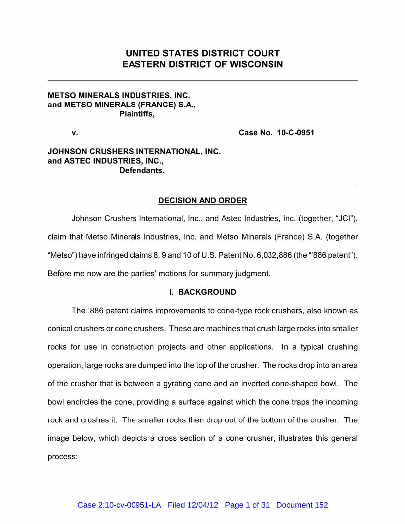
The ’886 patent claims improvements to cone-type rock crushers, also known as
conical crushers or cone crushers. These are machines that crush large rocks into smaller
rocks for use in construction projects and other applications. In a typical crushing
operation, large rocks are dumped into the top of the crusher. The rocks drop into an area
of the crusher that is between a gyrating cone and an inverted cone-shaped bowl. The
bowl encircles the cone, providing a surface against which the cone traps the incoming
rock and crushes it. The smaller rocks then drop out of the bottom of the crusher. The
image below, which depicts a cross section of a cone crusher, illustrates this general
process:
Case 2:10-cv-00951-LA Filed 12/04/12 Page 1 of 31 Document 152
2
Because the operator of a cone crusher will want to make small rocks of different
sizes, it is important to be able to adjust the spacing between the bowl and the cone—the
smaller the space between the bowl and the cone, the smaller the resulting rock. In a
typical cone crusher, adjustability is achieved by mounting the bowl in a threaded
engagement on a bowl support, which is part of the frame of the crusher. The bowl can
be screwed down on the threads to move the bowl closer to the cone, and it can be
unscrewed to move the bowl up and away from the cone. The spacing between the bowl
and the cone is known as the “closed side setting” or “CSS.” It is the CSS that determines
the size of the rock produced by the crusher.
Although an operator will want to be able to move the bowl closer to or farther away
from the cone between crushing operations, during a crushing operation the operator will
want the bowl to remain stationary. This is so because if the bowl moves up or down
during the operation, the size of the resulting rock will be inconsistent. Thus, the crusher
Case 2:10-cv-00951-LA Filed 12/04/12 Page 2 of 31 Document 152
In the image, there are diamond shapes between the threads. These are inserts1
designed to prevent galling or deformation of the threads. The inserts are the subject ofclaims in the ’886 patent which are not at issue in the present case.
3
must be equipped with a mechanism that “locks” the bowl in place during crushing
operations. When the operation is over, the operator must be able to release the lock so
that he or she can move the bowl as needed for the next operation.
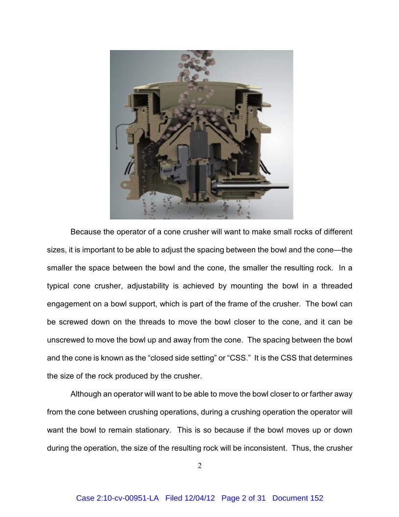
Claims 8, 9 and 10 of the ’886 patent relate to a mechanism that performs the
locking function on a cone crusher. JCI’s “Kodiak” and “Kodiak Plus” crushers embody this
mechanism. In this embodiment, a component known as a lock ring sits atop of the bowl
support and encircles the bowl, as depicted in the cross-sectional image below (the lock
ring is colored green):
Like the surface of the bowl support, the surface of the lock ring has threads that match
the threads on the outside surface of the bowl. 1
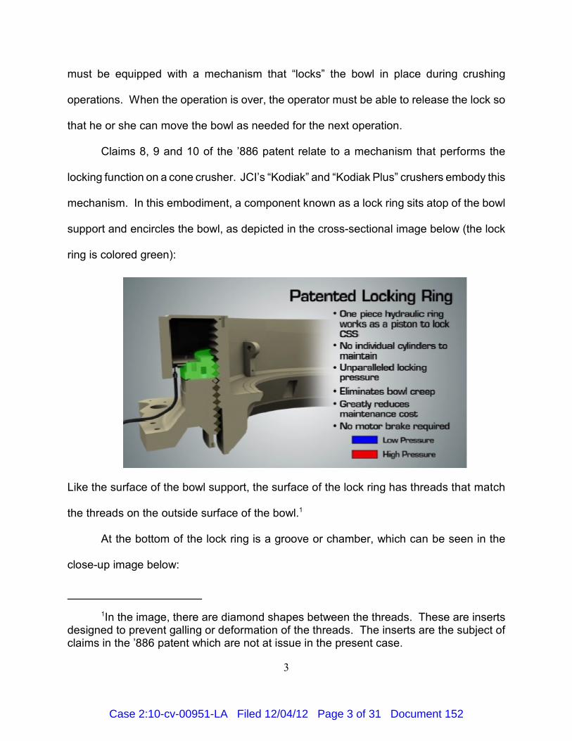
At the bottom of the lock ring is a groove or chamber, which can be seen in the
close-up image below:
Case 2:10-cv-00951-LA Filed 12/04/12 Page 3 of 31 Document 152
4
The groove or chamber contains a piston (shown in gray) and a seal (shown in black).
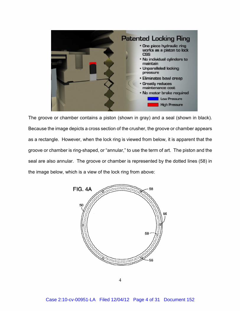
Because the image depicts a cross section of the crusher, the groove or chamber appears
as a rectangle. However, when the lock ring is viewed from below, it is apparent that the
groove or chamber is ring-shaped, or “annular,” to use the term of art. The piston and the
seal are also annular. The groove or chamber is represented by the dotted lines (58) in
the image below, which is a view of the lock ring from above:
Case 2:10-cv-00951-LA Filed 12/04/12 Page 4 of 31 Document 152
5
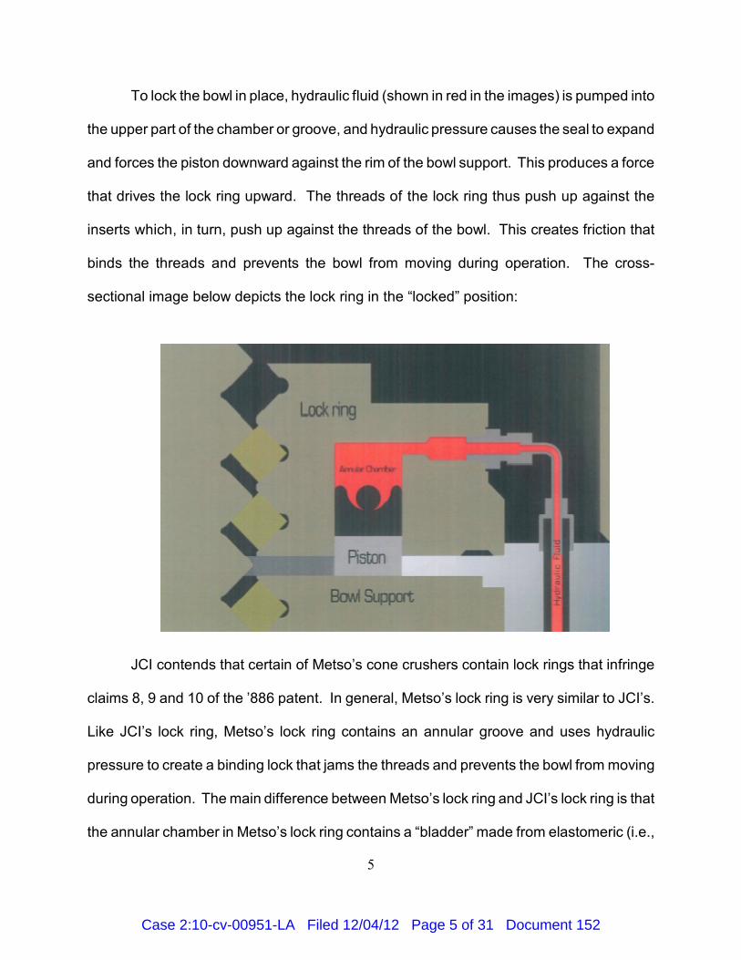
To lock the bowl in place, hydraulic fluid (shown in red in the images) is pumped into
the upper part of the chamber or groove, and hydraulic pressure causes the seal to expand
and forces the piston downward against the rim of the bowl support. This produces a force
that drives the lock ring upward. The threads of the lock ring thus push up against the
inserts which, in turn, push up against the threads of the bowl. This creates friction that
binds the threads and prevents the bowl from moving during operation. The cross-
sectional image below depicts the lock ring in the “locked” position:
JCI contends that certain of Metso’s cone crushers contain lock rings that infringe
claims 8, 9 and 10 of the ’886 patent. In general, Metso’s lock ring is very similar to JCI’s.
Like JCI’s lock ring, Metso’s lock ring contains an annular groove and uses hydraulic
pressure to create a binding lock that jams the threads and prevents the bowl from moving
during operation. The main difference between Metso’s lock ring and JCI’s lock ring is that
the annular chamber in Metso’s lock ring contains a “bladder” made from elastomeric (i.e.,
Case 2:10-cv-00951-LA Filed 12/04/12 Page 5 of 31 Document 152
6
rubber-like) material instead of a seal. In Metso’s lock ring, hydraulic fluid is pumped into
this bladder, which causes the bladder to expand or inflate. As the bladder expands, it
pushes against an annular piston. These forces drive the lock ring upward and cause the
threads to jam.
II. CLAIM LANGUAGE AND CONSTRUCTION
Claims 8, 9 and 10 of the ’886 patent are reproduced below. The parts of the claims
that had to be construed during earlier proceedings in this case are underlined.
8. A rock crusher comprising:
a conical shaped bowl, a cone mounted for oscillating movement within theconical shaped bowl, said bowl being vertically adjustable relative tothe cone for crushing rock to specific sizes;
a frame including an annular bowl support, said bowl adjustably supportedwithin said annular bowl support for vertical adjustment of the bowlrelative to the cone;
said vertical adjustment provided by mated screw threads on said supportand said bowl whereby the bowl is screwed up or down on the supportand thereby closer or farther away from said bowl;
an annular lock ring having a screw thread mated to the bowl and screwedonto the bowl and defining an annular surface in abutment with anannular surface of the support;
an annular chamber provided in one of the lock ring and bowl support andan annular piston fitted to the chamber, said piston providing theabutment surface for one of said lock ring and bowl support; and
a hydraulic fluid source providing hydraulic fluid to the chamber, and acontrol for controlling the hydraulic fluid flow to the chamber for urgingmovement of the annular piston toward the surface of the other of thelock ring and support and thereby producing a binding-type lock thatinhibits screw movement of the bowl.
9. A rock crusher as defined in claim 8 wherein the piston is providedwith a seal portion between the piston and hydraulic fluid and expands under
Case 2:10-cv-00951-LA Filed 12/04/12 Page 6 of 31 Document 152
7
pressure to seal the chamber and induces movement of the piston againstthe other of the lock ring and bowl support.
10. A rock crusher as defined in claim 9 wherein the annular chamberis provided in the lock ring.
Substituting the results of claim construction into the claims results in the following:
8. A rock crusher comprising:
a conical shaped bowl, a cone mounted for oscillating movement within theconical shaped bowl, said bowl being vertically adjustable relative tothe cone for crushing rock to specific sizes;
a frame including an annular bowl support, said bowl adjustably supportedwithin said annular bowl support for vertical adjustment of the bowlrelative to the cone;
said vertical adjustment provided by mated screw threads on said supportand said bowl whereby the bowl is screwed up or down on the supportand thereby closer or farther away from said cone;
an annular lock ring having a screw thread mated to the bowl and screwedonto the bowl and defining an annular surface of the lock ring inabutment with an annular surface of the support;
an annular chamber provided in one of the lock ring and bowl support anda ring-shaped component that fits snugly into the chamber and movesrelative to the chamber in response to fluid pressure on one side,providing the abutment surface for one of said lock ring and bowlsupport; and
a hydraulic fluid source providing hydraulic fluid to the chamber so that achange in pressure in the chamber will influence the ring-shapedcomponent to move with respect to the chamber, and a control forcontrolling the hydraulic fluid flow to the chamber for causingmovement of the ring-shaped component that moves relative to thechamber in response to fluid pressure on one side toward the surfaceof the one of the lock ring and bowl support that does not include thering-shaped chamber and thereby producing a binding-type lock thatinhibits screw movement of the bowl.
9. A rock crusher as defined in claim 8 wherein the ring-shapedcomponent that moves relative to the chamber in response to fluid pressure
Case 2:10-cv-00951-LA Filed 12/04/12 Page 7 of 31 Document 152
8
on one side is provided with a seal portion between the ring-shapedcomponent that moves relative to the chamber in response to fluid pressureon one side and the hydraulic fluid and wherein the seal portion expandsunder pressure to seal the chamber and causes movement of the ring-shaped component that moves relative to the chamber in response to fluidpressure on one side against the one of the lock ring and bowl support thatdoes not include the ring-shaped chamber.
10. A rock crusher as defined in claim 9 wherein the annular chamberis provided in the lock ring.
III. DISCUSSION
In its motion for summary judgment, Metso argues that claims 8, 9 and 10 of the
’886 patent are invalid because either the prior art anticipates the inventions described in
the claims or any differences between the claims and the prior art are such that the
inventions would have been obvious to a person having ordinary skill in the art. A claim
in a patent is presumed to be valid, and a party challenging this presumption of validity
must prove that the claim is invalid by clear and convincing evidence. See 35 U.S.C. §
282(a); Microsoft Corp. v. i4i Ltd. P’ship, 131 S. Ct. 2238, 2242 (2011).
A. Anticipation
In patent parlance, “anticipation” means lack of novelty. Roughly speaking, if an
invention already exists or is known at the time a patent is sought, the invention is not
novel and cannot be patented. If the Patent and Trademark Office (“PTO”) mistakenly
issues a patent for an invention that is not novel, the patent is invalid. This rule appears
in 35 U.S.C. § 102, which states in pertinent part as follows:
A person shall be entitled to a patent unless–
(a) the invention was known or used by others in this country, or patented ordescribed in a printed publication in this or a foreign country, before theinvention thereof by the applicant for patent, or
Case 2:10-cv-00951-LA Filed 12/04/12 Page 8 of 31 Document 152
9
(b) the invention was patented or described in a printed publication in this ora foreign country or in public use or on sale in this country, more than oneyear prior to the date of the application for patent in the United States . . . .
In the present case, Metso argues that the inventions described in claims 8, 9 and
10 of the ’886 patent were “described in a printed publication in this or a foreign country”
and were “on sale in this country” more than one year prior to the date of the application
for the ’886 patent. To show that a claimed invention was described in a printed
publication more than one year prior to the date of the patent application, Metso must point
to a single prior art reference that discloses each and every element of the claimed
invention. See Minn. Mining & Mfg. Co. v. Johnson & Johnson Orthopaedics, Inc., 976
F.2d 1559, 1565 (Fed. Cir. 1992). To show that a claimed invention was on sale in this
country more than one year prior to the date of the patent application, Metso must prove
that a single device on sale in this country at the relevant time included each and every
element of the claimed invention—i.e., that the patent claim “reads on” such a device. Id.
Moreover, Metso must show that the device described in the printed publication or
embodied in the device sold is literally identical to the claimed invention, not just
functionally equivalent to the claimed invention. See, e.g., Old Reliable Wholesale, Inc.
v. Cornell Corp., 635 F.3d 539, 544–45 (Fed. Cir. 2011).
The application that matured into the ’886 patent was filed with the PTO on March
18, 1999. Thus, the “critical date” of the ’886 patent is March 18, 1998. Metso contends
that one of its own cone crushers was on sale in the United States prior to that date, and
that this crusher embodied the inventions of claims 8, 9 and 10 of the ’886 patent. Metso
introduced this crusher, the HP100, in 1996. Metso made changes to the design of the
HP100 in late 2000 and again in 2007, and hence I will refer to the HP100 as it existed
Case 2:10-cv-00951-LA Filed 12/04/12 Page 9 of 31 Document 152
No information regarding the original HP100 was before the PTO when it issued2
the ’886 patent.
10
between 1996 and 2000 as the “original” HP100. JCI contends that the changes made in
late 2000 and preserved in 2007 resulted in a design that infringes claims 8, 9 and 10 of
the ’886 patent. However, JCI contends that the original HP100 does not infringe those
claims. Metso, however, contends that the claims as construed read on the original
HP100, and that therefore the original HP100, which JCI concedes was sold in the United
States prior to March 18, 1998, anticipates and invalidates those claims. Metso also
contends that the instruction manual for the original HP100 constitutes a printed publication
that discloses each and every element of claims 8, 9 and 10.2
The parties agree that the original HP100 meets the elements stated in the first four
subparagraphs of claim 8: a cone and a vertically adjustable bowl mounted in a threaded
engagement, with the bowl held in place during operation of the crusher by a lock ring.
See Joint Statement of Undisputed Facts (“JSF”) ¶ 44. The parties also agree that the
original HP100 uses hydraulic fluid to produce the force that binds the threads, id. ¶ 47,
and that the hydraulic fluid is pumped into a ring-shaped groove or chamber in either the
lock ring or the bowl support, id. ¶ 50. However, unlike JCI’s embodiment of claims 8, 9
and 10, the original HP100 pumps hydraulic fluid into a bladder located in the groove or
chamber, rather than directly into the groove or chamber. Still, this difference does not
prevent anticipation, because as I have construed the claims, they read on a device that
pumps hydraulic fluid into a bladder located in the groove or chamber. See Nov. 28, 2011
Order at 17–19, ECF No. 49. Indeed, the post-2000 and post-2007 versions of the HP100
also rely on bladders, as do the other accused devices.
Case 2:10-cv-00951-LA Filed 12/04/12 Page 10 of 31 Document 152
11
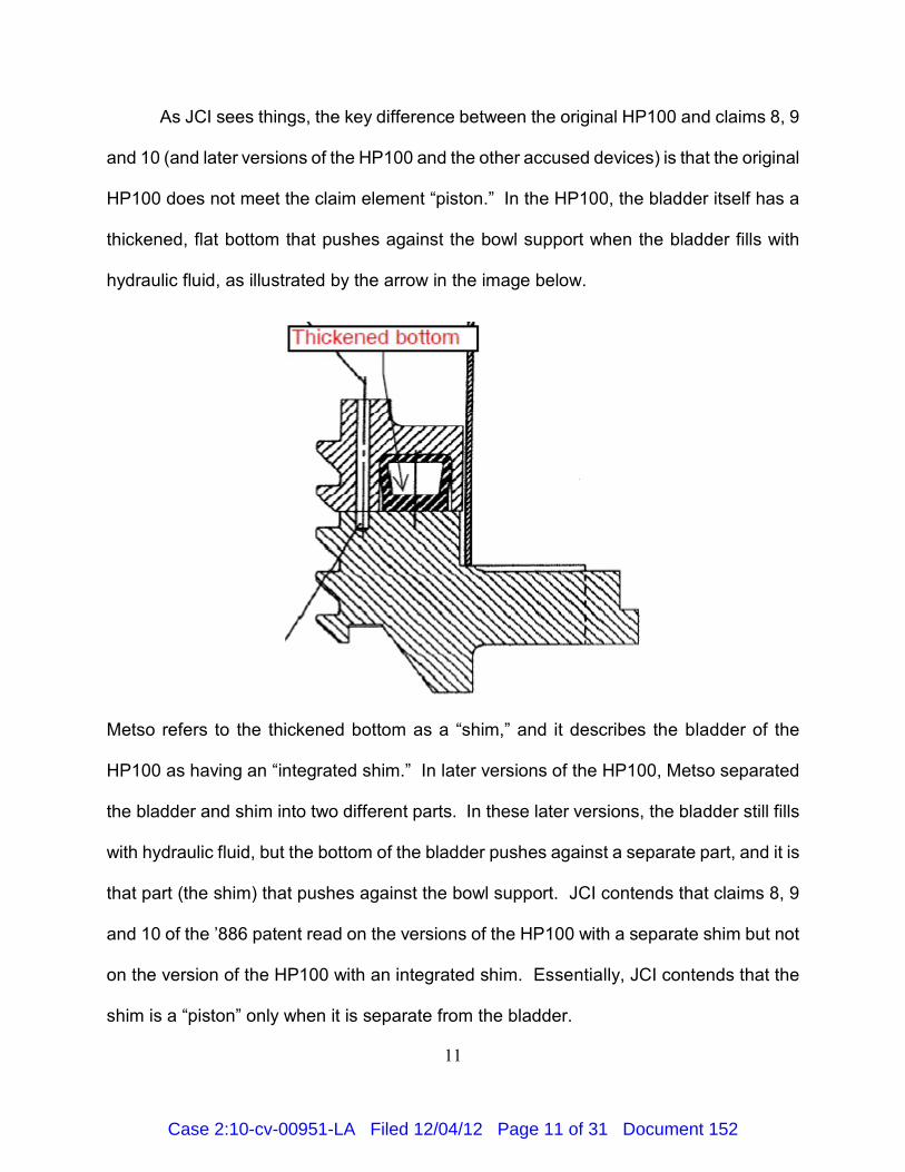
As JCI sees things, the key difference between the original HP100 and claims 8, 9
and 10 (and later versions of the HP100 and the other accused devices) is that the original
HP100 does not meet the claim element “piston.” In the HP100, the bladder itself has a
thickened, flat bottom that pushes against the bowl support when the bladder fills with
hydraulic fluid, as illustrated by the arrow in the image below.
Metso refers to the thickened bottom as a “shim,” and it describes the bladder of the
HP100 as having an “integrated shim.” In later versions of the HP100, Metso separated
the bladder and shim into two different parts. In these later versions, the bladder still fills
with hydraulic fluid, but the bottom of the bladder pushes against a separate part, and it is
that part (the shim) that pushes against the bowl support. JCI contends that claims 8, 9
and 10 of the ’886 patent read on the versions of the HP100 with a separate shim but not
on the version of the HP100 with an integrated shim. Essentially, JCI contends that the
shim is a “piston” only when it is separate from the bladder.
Case 2:10-cv-00951-LA Filed 12/04/12 Page 11 of 31 Document 152
12
I conclude that claim 8 reads on the original HP100. Claim 8 requires “an annular
piston fitted to the chamber, said piston providing the abutment surface for” either the lock
ring or the bowl support. Moreover, I accepted JCI’s claim-construction argument and
construed the claim language “an annular piston fitted to the chamber” to mean ”a
ring-shaped component that fits snugly into the chamber and moves relative to the
chamber in response to fluid pressure on one side.” See Nov. 28, 2011 Order at 17, ECF
No. 49. Thus, as construed, claim 8 requires a ring-shaped component that fits snugly into
the chamber and that moves relative to the chamber in response to fluid pressure on one
side, and that the ring-shaped component provide the abutment surface for either the lock
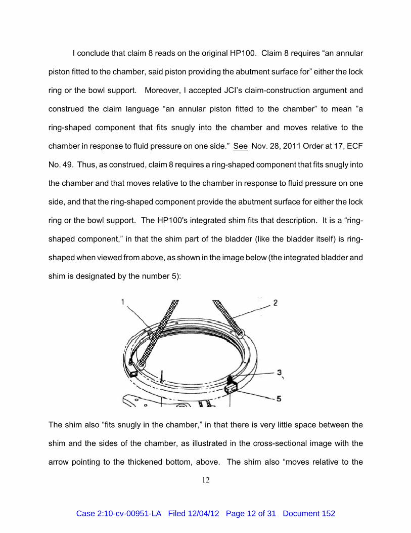
ring or the bowl support. The HP100's integrated shim fits that description. It is a “ring-
shaped component,” in that the shim part of the bladder (like the bladder itself) is ring-
shaped when viewed from above, as shown in the image below (the integrated bladder and
shim is designated by the number 5):
The shim also “fits snugly in the chamber,” in that there is very little space between the
shim and the sides of the chamber, as illustrated in the cross-sectional image with the
arrow pointing to the thickened bottom, above. The shim also “moves relative to the
Case 2:10-cv-00951-LA Filed 12/04/12 Page 12 of 31 Document 152
Because the sale of the original HP100 invalidates claim 8, I do not need to3
separately consider whether the original HP100's instruction manual constitutes aninvalidating “printed publication.”
13
chamber in response to fluid pressure on one side,” in that when hydraulic fluid is pumped
into the chamber, it puts pressure on the top side of the shim, and then the resulting forces
push the chamber upwards and the shim downwards into the bowl support. Finally, the
shim provides the necessary abutment surface. Nothing in the claim language or in my
construction of the claim language requires that the piston be physically separate from the
surrounding parts of the crusher, and so the fact that the shim and the bladder are
“integrated” is inconsequential. Therefore, the original HP100 anticipates and invalidates
claim 8. 3
Claims 9 and 10 are different, however. Claim 9 adds the requirement that a “seal
portion” be placed “between the piston and hydraulic fluid,” and claim 10 incorporates that
requirement. The bladder of the original HP100 could be described as a “seal portion,” but
because the bladder and the shim are integrated, with the shim forming the bottom of the
bladder, the bladder is not between the shim (piston) and the hydraulic fluid: when
hydraulic fluid enters the chamber, it also enters the bladder and comes into direct contact
with the top of the shim. Thus, the original HP100 does not literally contain all the
elements of claims 9 and 10. Likewise, its instruction manual does not literally disclose all
the elements of claims 9 and 10. Therefore, neither the original HP100 nor its instruction
manual anticipates claims 9 and 10.
Case 2:10-cv-00951-LA Filed 12/04/12 Page 13 of 31 Document 152
14
B. Obviousness
A patent cannot be issued when “the differences between the subject matter sought
to be patented and the prior art are such that the subject matter as a whole would have
been obvious at the time the invention was made to a person having ordinary skill in the
art to which said subject matter pertains.” 35 U.S.C. § 103(a). A principal reason for
refusing to allow patents on what is obvious is that it is tantamount to withdrawing from
public use and into monopoly methods and techniques that were previously available and
known to persons having ordinary skill in the art. See KSR Int’l Co. v. Teleflex, Inc., 550
U.S. 398, 415–16 (2007). Thus, obviousness is similar to anticipation, with one difference
being that anticipation will invalidate a patent only when the patent claims an invention that
is identical to what is already present in the prior art, while obviousness will invalidate a
patent when no such identical device is present in the prior art but the invention is nothing
but an obvious modification of the prior art. Cf. Lewmar Marine, Inc. v. Barient, Inc., 827
F.2d 744, 747–48 (Fed. Cir. 1987).
The Supreme Court has instructed the lower courts to use an “expansive and
flexible approach” to the question of obviousness, and thus there is no rigid test for
determining whether a patent claims what would have been obvious to a person having
ordinary skill in the art at the relevant time. KSR, 550 U.S. at 415. Instead, a court must
consider the items described in Graham v. John Deere Co., 383 U.S. 1 (1966): (1) the
scope and content of the prior art; (2) the level of ordinary skill in the art; (3) the differences
between the claimed invention and the prior art; and (4) the so-called “secondary
considerations” or “objective considerations.” See KSR, 550 U.S. at 406. These
secondary or objective considerations include “commercial success,” “long felt but
Case 2:10-cv-00951-LA Filed 12/04/12 Page 14 of 31 Document 152
JCI concedes that a bladder satisfies the claim element “seal portion,” either literally4
or under the doctrine of equivalents. See JCI Br. at 24–26, ECF No. 113; JCI Reply Br. at9–10, ECF No. 9–10.
In the discussion below, I do not discuss the level of ordinary skill in the art, as the5
parties appear to be in agreement on that issue. They define a person having ordinary skillin the art as one with significant experience in designing, manufacturing, or operating conecrushers. See Metso Proposed Findings of Fact (“MPFF”) ¶ 158.
15
unsolved needs,” “failure of others,” and various other considerations. See Graham, 383
at 17–18.
I have already determined that claim 8 is invalid because the original HP100
anticipates it. Moreover, the only difference between claims 9 and 10 and the original
HP100 is that the “seal portion” of the HP100—i.e., the bladder —is not “between” the4
piston and the hydraulic fluid. Thus, to determine whether claims 9 and 10 are invalid for
obviousness, the only question is whether requiring the seal portion to be “between” the
piston and the hydraulic fluid would have been obvious to a person having ordinary skill in
the art at the time of JCI’s invention. Put differently, the only question is whether
separating the seal and piston into two unattached parts would have been obvious to a
person having ordinary skill in the art. To ask that question is almost to answer it: it is
generally obvious to separate a single component into two components that together
perform the same function as the single component. See Reed Propeller Co., Inc. v.
United States, 42 F. Supp. 545, 568 (Ct. Cl. 1942). Nonetheless, in the discussion below,
I demonstrate that the inventions of claims 9 and 10 would have been obvious to a person
having ordinary skill in the art at the relevant time.5
At the time of JCI’s invention, one well known means for locking the bowl in place
during operation of a cone crusher was to use a series of separate hydraulic clamping
Case 2:10-cv-00951-LA Filed 12/04/12 Page 15 of 31 Document 152
16
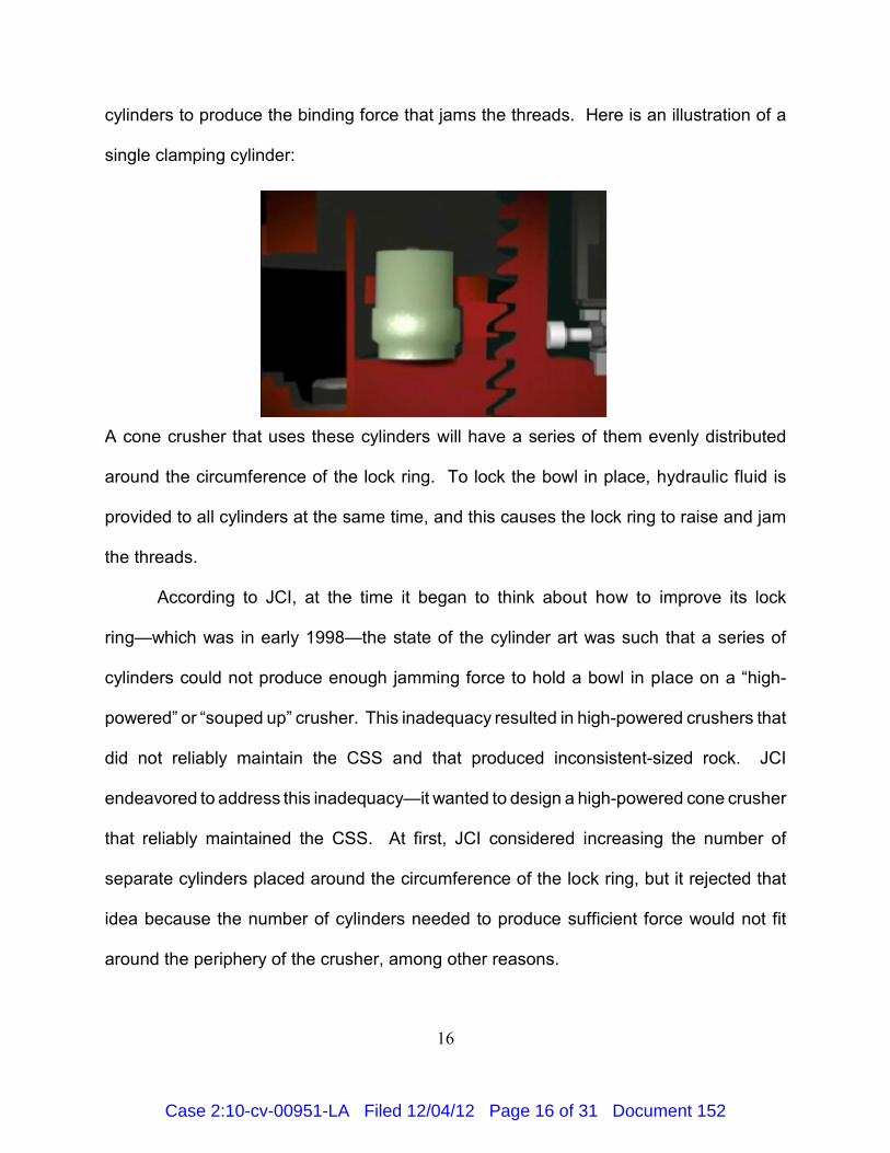
cylinders to produce the binding force that jams the threads. Here is an illustration of a
single clamping cylinder:
A cone crusher that uses these cylinders will have a series of them evenly distributed
around the circumference of the lock ring. To lock the bowl in place, hydraulic fluid is
provided to all cylinders at the same time, and this causes the lock ring to raise and jam
the threads.
According to JCI, at the time it began to think about how to improve its lock
ring—which was in early 1998—the state of the cylinder art was such that a series of
cylinders could not produce enough jamming force to hold a bowl in place on a “high-
powered” or “souped up” crusher. This inadequacy resulted in high-powered crushers that
did not reliably maintain the CSS and that produced inconsistent-sized rock. JCI
endeavored to address this inadequacy—it wanted to design a high-powered cone crusher
that reliably maintained the CSS. At first, JCI considered increasing the number of
separate cylinders placed around the circumference of the lock ring, but it rejected that
idea because the number of cylinders needed to produce sufficient force would not fit
around the periphery of the crusher, among other reasons.
Case 2:10-cv-00951-LA Filed 12/04/12 Page 16 of 31 Document 152
The Hesse patent states that the bladder can be either a “circumferential” tube or6
a “group of tubes.” U.S. Patent No. 3,272,446, col. 2, ll.57–59.
17
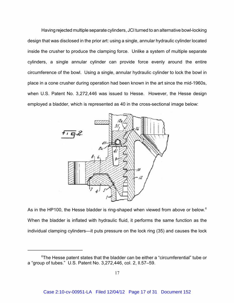
Having rejected multiple separate cylinders, JCI turned to an alternative bowl-locking
design that was disclosed in the prior art: using a single, annular hydraulic cylinder located
inside the crusher to produce the clamping force. Unlike a system of multiple separate
cylinders, a single annular cylinder can provide force evenly around the entire
circumference of the bowl. Using a single, annular hydraulic cylinder to lock the bowl in
place in a cone crusher during operation had been known in the art since the mid-1960s,
when U.S. Patent No. 3,272,446 was issued to Hesse. However, the Hesse design
employed a bladder, which is represented as 40 in the cross-sectional image below:
As in the HP100, the Hesse bladder is ring-shaped when viewed from above or below.6
When the bladder is inflated with hydraulic fluid, it performs the same function as the
individual clamping cylinders—it puts pressure on the lock ring (35) and causes the lock
Case 2:10-cv-00951-LA Filed 12/04/12 Page 17 of 31 Document 152
The Hesse patent was not before the PTO when it issued the ’886 patent.7
The Durand patent was not before the PTO when it issued the ’886 patent.8
18
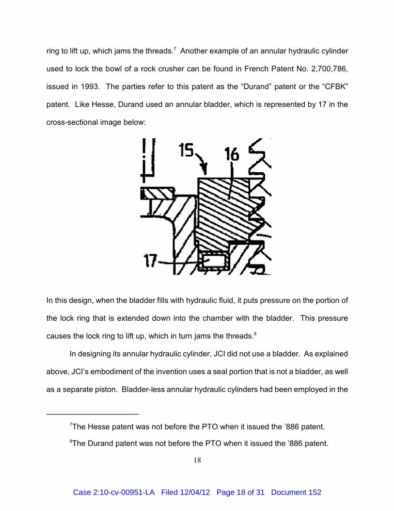
ring to lift up, which jams the threads. Another example of an annular hydraulic cylinder7
used to lock the bowl of a rock crusher can be found in French Patent No. 2,700,786,
issued in 1993. The parties refer to this patent as the “Durand” patent or the “CFBK”
patent. Like Hesse, Durand used an annular bladder, which is represented by 17 in the
cross-sectional image below:
In this design, when the bladder fills with hydraulic fluid, it puts pressure on the portion of
the lock ring that is extended down into the chamber with the bladder. This pressure
causes the lock ring to lift up, which in turn jams the threads.8
In designing its annular hydraulic cylinder, JCI did not use a bladder. As explained
above, JCI’s embodiment of the invention uses a seal portion that is not a bladder, as well
as a separate piston. Bladder-less annular hydraulic cylinders had been employed in the
Case 2:10-cv-00951-LA Filed 12/04/12 Page 18 of 31 Document 152
The Meder patent was not before the PTO when it issued the ’886 patent.9
19
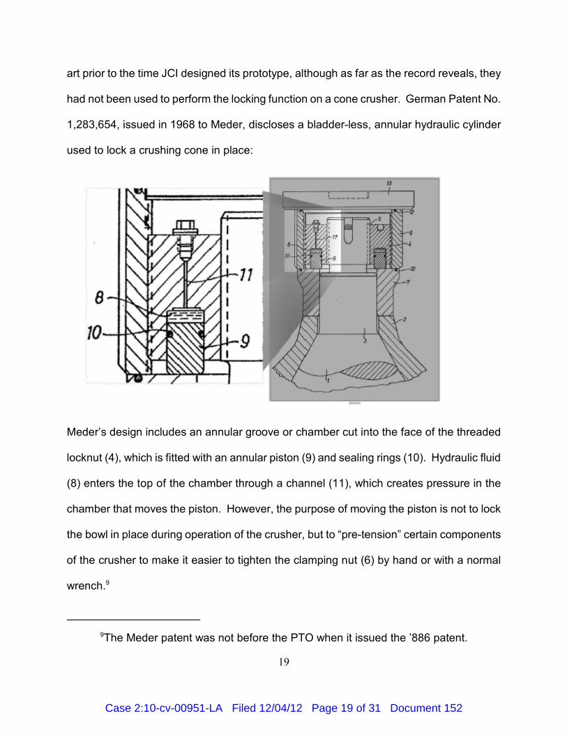
art prior to the time JCI designed its prototype, although as far as the record reveals, they
had not been used to perform the locking function on a cone crusher. German Patent No.
1,283,654, issued in 1968 to Meder, discloses a bladder-less, annular hydraulic cylinder
used to lock a crushing cone in place:
Meder’s design includes an annular groove or chamber cut into the face of the threaded
locknut (4), which is fitted with an annular piston (9) and sealing rings (10). Hydraulic fluid
(8) enters the top of the chamber through a channel (11), which creates pressure in the
chamber that moves the piston. However, the purpose of moving the piston is not to lock
the bowl in place during operation of the crusher, but to “pre-tension” certain components
of the crusher to make it easier to tighten the clamping nut (6) by hand or with a normal
wrench. 9
Case 2:10-cv-00951-LA Filed 12/04/12 Page 19 of 31 Document 152
20
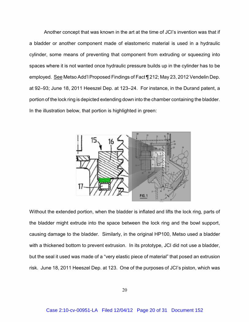
Another concept that was known in the art at the time of JCI’s invention was that if
a bladder or another component made of elastomeric material is used in a hydraulic
cylinder, some means of preventing that component from extruding or squeezing into
spaces where it is not wanted once hydraulic pressure builds up in the cylinder has to be
employed. See Metso Add’l Proposed Findings of Fact ¶ 212; May 23, 2012 Vendelin Dep.
at 92–93; June 18, 2011 Heeszel Dep. at 123–24. For instance, in the Durand patent, a
portion of the lock ring is depicted extending down into the chamber containing the bladder.
In the illustration below, that portion is highlighted in green:
Without the extended portion, when the bladder is inflated and lifts the lock ring, parts of
the bladder might extrude into the space between the lock ring and the bowl support,
causing damage to the bladder. Similarly, in the original HP100, Metso used a bladder
with a thickened bottom to prevent extrusion. In its prototype, JCI did not use a bladder,
but the seal it used was made of a “very elastic piece of material” that posed an extrusion
risk. June 18, 2011 Heeszel Dep. at 123. One of the purposes of JCI’s piston, which was
Case 2:10-cv-00951-LA Filed 12/04/12 Page 20 of 31 Document 152
21
made of hard plastic, was to prevent the seal from extruding into the space between the
lock ring and the bowl support. Id. at 123–24.
Thus, at the time JCI designed its prototype, a person having ordinary skill in the art
would have known that one could use an annular hydraulic cylinder to lock the bowl of a
cone crusher in place during operation. Such a person also would have known that one
could construct an annular hydraulic cylinder in at least two different ways: with a bladder,
or without a bladder. Finally, such a person would have known that if one used elastomeric
material in a hydraulic cylinder, one needed to employ a means for preventing extrusion.
In light of this common knowledge in the art, it is hard to see anything in JCI’s invention
that would not have been obvious to a person having ordinary skill in the art at the time.
Perhaps the use of a bladder-less, annular hydraulic cylinder to lock the bowl in place
during operation of the crusher would not have been obvious, but claims 9 and 10 of the
’886 patent are not limited to rock crushers without bladders.
So far, I have discussed the obviousness of JCI’s invention generally and have not
focused on the sole difference between claims 9 and 10 and the original HP100: the
separation of the integrated bladder and shim into two components. However, as
explained below, the design history of the HP100 confirms that JCI’s separate seal and
piston was not an unobvious modification of the prior art.
According to Metso, the design process for the HP100 began in 1993, when
engineers met in Waukesha, Wisconsin to brainstorm possible design changes to two of
its existing crushers, the HP400 and the HP300, which at the time used a series of
separate cylinders to lock the bowl in place. The engineers, who were familiar with the
Case 2:10-cv-00951-LA Filed 12/04/12 Page 21 of 31 Document 152
22
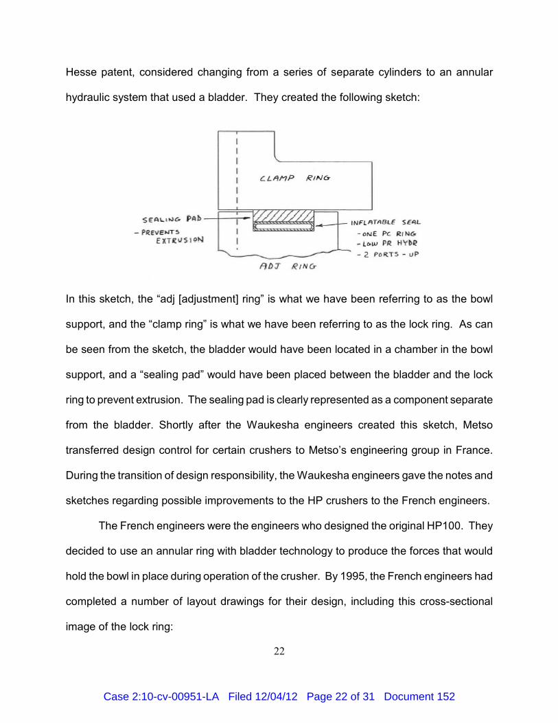
Hesse patent, considered changing from a series of separate cylinders to an annular
hydraulic system that used a bladder. They created the following sketch:
In this sketch, the “adj [adjustment] ring” is what we have been referring to as the bowl
support, and the “clamp ring” is what we have been referring to as the lock ring. As can
be seen from the sketch, the bladder would have been located in a chamber in the bowl
support, and a “sealing pad” would have been placed between the bladder and the lock
ring to prevent extrusion. The sealing pad is clearly represented as a component separate
from the bladder. Shortly after the Waukesha engineers created this sketch, Metso
transferred design control for certain crushers to Metso’s engineering group in France.
During the transition of design responsibility, the Waukesha engineers gave the notes and
sketches regarding possible improvements to the HP crushers to the French engineers.
The French engineers were the engineers who designed the original HP100. They
decided to use an annular ring with bladder technology to produce the forces that would
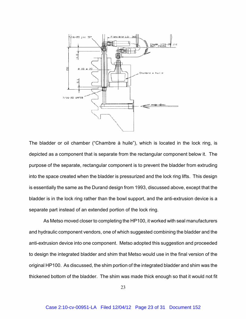
hold the bowl in place during operation of the crusher. By 1995, the French engineers had
completed a number of layout drawings for their design, including this cross-sectional
image of the lock ring:
Case 2:10-cv-00951-LA Filed 12/04/12 Page 22 of 31 Document 152
23
The bladder or oil chamber (“Chambre à huile”), which is located in the lock ring, is
depicted as a component that is separate from the rectangular component below it. The
purpose of the separate, rectangular component is to prevent the bladder from extruding
into the space created when the bladder is pressurized and the lock ring lifts. This design
is essentially the same as the Durand design from 1993, discussed above, except that the
bladder is in the lock ring rather than the bowl support, and the anti-extrusion device is a
separate part instead of an extended portion of the lock ring.
As Metso moved closer to completing the HP100, it worked with seal manufacturers
and hydraulic component vendors, one of which suggested combining the bladder and the
anti-extrusion device into one component. Metso adopted this suggestion and proceeded
to design the integrated bladder and shim that Metso would use in the final version of the
original HP100. As discussed, the shim portion of the integrated bladder and shim was the
thickened bottom of the bladder. The shim was made thick enough so that it would not fit
Case 2:10-cv-00951-LA Filed 12/04/12 Page 23 of 31 Document 152
24
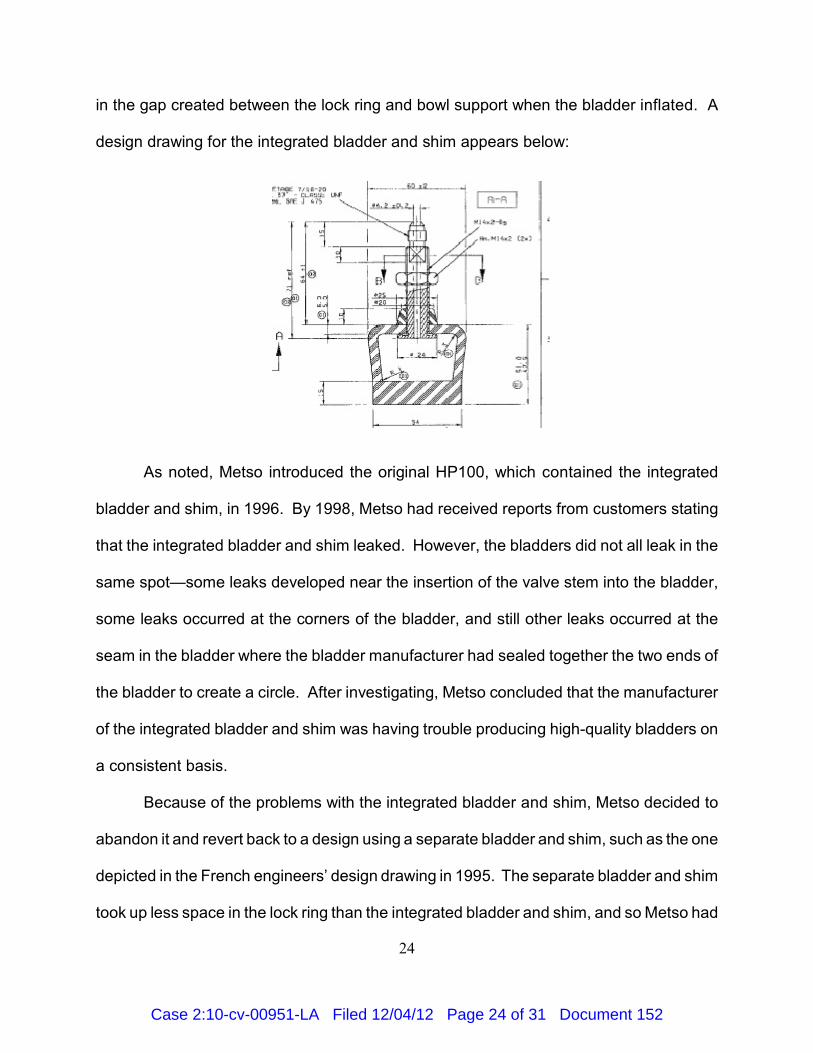
in the gap created between the lock ring and bowl support when the bladder inflated. A
design drawing for the integrated bladder and shim appears below:
As noted, Metso introduced the original HP100, which contained the integrated
bladder and shim, in 1996. By 1998, Metso had received reports from customers stating
that the integrated bladder and shim leaked. However, the bladders did not all leak in the
same spot—some leaks developed near the insertion of the valve stem into the bladder,
some leaks occurred at the corners of the bladder, and still other leaks occurred at the
seam in the bladder where the bladder manufacturer had sealed together the two ends of
the bladder to create a circle. After investigating, Metso concluded that the manufacturer
of the integrated bladder and shim was having trouble producing high-quality bladders on
a consistent basis.
Because of the problems with the integrated bladder and shim, Metso decided to
abandon it and revert back to a design using a separate bladder and shim, such as the one
depicted in the French engineers’ design drawing in 1995. The separate bladder and shim
took up less space in the lock ring than the integrated bladder and shim, and so Metso had
Case 2:10-cv-00951-LA Filed 12/04/12 Page 24 of 31 Document 152
25
to change the dimensions of the chamber in the lock ring when it changed to the separate
bladder and shim. To allow the current owners of the HP100s to continue using the lock
ring associated with the integrated bladder and shim design and to allow the inventory of
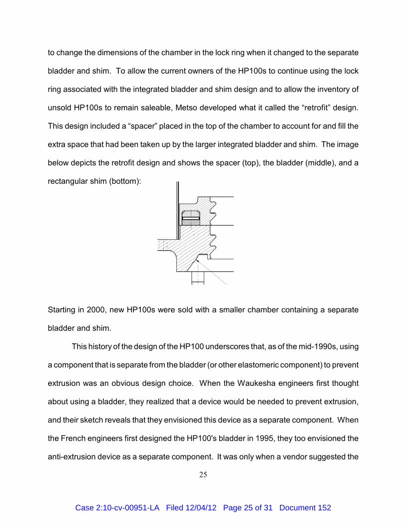
unsold HP100s to remain saleable, Metso developed what it called the “retrofit” design.
This design included a “spacer” placed in the top of the chamber to account for and fill the
extra space that had been taken up by the larger integrated bladder and shim. The image
below depicts the retrofit design and shows the spacer (top), the bladder (middle), and a
rectangular shim (bottom):
Starting in 2000, new HP100s were sold with a smaller chamber containing a separate
bladder and shim.
This history of the design of the HP100 underscores that, as of the mid-1990s, using
a component that is separate from the bladder (or other elastomeric component) to prevent
extrusion was an obvious design choice. When the Waukesha engineers first thought
about using a bladder, they realized that a device would be needed to prevent extrusion,
and their sketch reveals that they envisioned this device as a separate component. When
the French engineers first designed the HP100's bladder in 1995, they too envisioned the
anti-extrusion device as a separate component. It was only when a vendor suggested the
Case 2:10-cv-00951-LA Filed 12/04/12 Page 25 of 31 Document 152
JCI contends that the French engineers did not rely on their drawing from 199510
when producing the retrofit design. JCI also contends that the French engineers in 1995did not rely on the Waukesha engineers’ drawing from 1993 when producing their designfor the separate bladder and shim. If these things are true, then that is only further proofthat the separate bladder and shim is an obvious design choice: three groups of engineersindependently designed a lock ring containing a separate bladder and shim withoutknowledge of the other groups’ designs.
26
possibility of integrating the anti-extrusion component into the bladder that the French
engineers changed their design. When the integrated bladder and shim proved to be
problematic in practice, the French engineers reverted back to their original design
involving a separate bladder and shim. Thus, if anything, it was the integrated bladder and
shim that represented a possible unobvious modification of the prior art. When that design
did not pan out, the engineers reverted back to what persons having ordinary skill in the
art at the time would have considered the standard or default design, which was to
separate the bladder and shim into two components. Thus, JCI’s decision to put a “seal
portion” between the hydraulic fluid and the “piston,” as in claims 9 and 10, did not result
in a unobvious modification of the prior art.10
Considering the “secondary” or “objective” considerations from Graham v. John
Deere Co. does not alter this conclusion. JCI contends that six such considerations are
relevant. First, JCI contends that the relevant claims of the ’886 patent are not obvious
because they satisfied a “long-felt but unsolved need” in the industry. See Graham, 383
U.S. at 17. JCI contends that at the time of its invention there was a need for higher-
powered cone crushers that could reliably maintain the CSS and prevent bowl slippage.
Perhaps that is true, but JCI has not shown that the extremely minor differences between
claims 9 and 10 and the prior art resulted in a satisfaction of that need. See Geo. M.
Case 2:10-cv-00951-LA Filed 12/04/12 Page 26 of 31 Document 152
27
Martin Co. v. Allance Mach. Sys. Int’l LLC, 618 F.3d 1294, 1304 (Fed. Cir. 2010) (noting
that where differences between prior art and claimed invention are minimal, such
differences cannot be deemed to have satisfied any long-felt need). Indeed, it appears
that to the extent JCI’s Kodiak crushers satisfied any need for higher-powered crushers
that reliably maintained the CSS, that was because JCI switched from the separate, multi-
cylinder design to a design involving an annular hydraulic cylinder. See JCI Br. at 64
(stating that JCI’s annular design provided five times more clamping pressure than multi-
cylinder design). However, as discussed, using an annular hydraulic cylinder instead of
a series of separate cylinders to lock the bowl on a cone crusher was well known in the art
at the time of JCI’s invention.
Second, JCI contends that the original HP100 constitutes an example of “failure of
others.” See Graham, 383 U.S. at 17. However, even if Metso’s integrated bladder and
shim can be deemed a failure because it had a tendency to leak, that does not imply that
JCI’s design was not obvious. As described above, Metso’s decision to integrate the
bladder and shim was a modification of its previous design choice, which was to use a
separate bladder and shim. When the modification failed, Metso went back to the original
design. Thus, Metso’s attempt and failure does not imply that the original design was not
obvious. Indeed, the fact that the Waukesha engineers, the French engineers, and JCI’s
engineers each designed an annular hydraulic cylinder using a separate seal potion and
piston during the same approximate time period is strong evidence that using separate
components was an obvious choice. See Stewart-Warner Corp. v. City of Pontiac, Mich.,
767 F.2d 1563, 1570 (Fed. Cir. 1985).
Case 2:10-cv-00951-LA Filed 12/04/12 Page 27 of 31 Document 152
28
Third, JCI contends that its lock ring yielded surprising or unexpected results. The
caselaw states that an invention is less likely to have been obvious if a person having
ordinary skill in the art would have been surprised by the invention’s result. See, e.g., In re
Soni, 54 F.3d 746, 750 (Fed. Cir. 1995). JCI points out that the inventors of its prototype,
who were new to the rock-crushing industry as of 1998, see MPFF ¶ 66, were surprised
to learn that their annular design worked better than a design that relied on a series of
separate cylinders to lock the bowl. See Heeszel Decl. ¶¶ 16–17. However, JCI does not
explain what a person having ordinary skill in the art at the time of its prototype would have
expected when switching from a series of separate cylinders to a single, annular cylinder,
and so the fact that JCI’s inventors were surprised proves nothing. Moreover, JCI has
made no attempt to show that the results that surprised its inventors were attributable to
the only difference between claims 9 and 10 and the prior art—namely, the use of a “seal
portion” between the piston and hydraulic fluid. Again, it appears that any surprising result
was attributable to the use of an annular cylinder rather than a series of separate cylinders,
a solution that had already been adopted by Metso in the HP100 and by CFBK in the
Durand design—two designs that JCI’s engineers did not know about in 1998.
Fourth, JCI contends that the prior art “taught away” from the inventions of claims
9 and 10. In this regard, JCI first points to two French patents issued to Corbin—French
Patent Nos. 2,569,997 and 2,630,663. JCI claims that these patents teach away from
using a ring-shaped piston combined with a ring-shaped seal because such a combination
is a source of continuous leaks. However, the context of the Corbin patents makes clear
that they are teaching away from using a specific kind of piston-and-seal combination—one
that does not use a bladder. The Corbin patents employ the same bladder technology that
Case 2:10-cv-00951-LA Filed 12/04/12 Page 28 of 31 Document 152
29
appears in the Durand patent discussed above, and the portion of the Corbin patents cited
by JCI recommend using that technology rather than bladder-less technology because
bladder-less technology is prone to leaking. Thus, Corbin does not teach away from using
a bladder along with a separate piston; it teaches away from using any system that does
not involve a bladder at all. So, had JCI claimed an improved form of bladder-less
technology, one could say that the Corbin patents teach away from the claimed inventions.
But JCI drafted its claims to cover lock rings that employ bladder technology, and therefore
the Corbin patents do not teach away from what JCI claimed.
JCI also contends that the Meder patent discussed above teaches away from its
inventions. Recall that the Meder patent uses a bladder-less, annular hydraulic locking
system to “pre-tension” certain components on a rock crusher for the purpose of making
it easier to tighten other components by hand or with a normal wrench. JCI contends that
because the Meder hydraulic system is not used to provide a locking force while the
crusher is in operation, Meder teaches away from using a hydraulic system to provide a
locking force for the crusher during operation. However, that is not what Meder teaches.
Meder says nothing one way or the other about whether hydraulic systems could be used
to provide a locking force while the crusher is in operation. In any event, even assuming
that Meder in the 1960s taught away from using hydraulic systems to hold the bowl in place
on rock crushers, by the mid-1990s, using hydraulic systems for that purpose was common
in the art, as evidenced by the HP100, the Durand patent, the Corbin patents, and also all
rock crushers using a series of separate hydraulic clamping cylinders.
Fifth, JCI contends that its invention has received “industry praise.” See Geo. M.
Martin, 618 F.3d at 1305. This industry praise consists of a Metso internal marketing
Case 2:10-cv-00951-LA Filed 12/04/12 Page 29 of 31 Document 152
30
memorandum describing the allegedly infringing bladder-and-piston design of the post-
2000 HP100 as “proven” and “safer.” However, assuming that an internal Metso document
constitutes industry praise, there is no indication that this praise refers to the difference
between claims 9 and 10 and the prior art—i.e., the separation of the seal portion and
piston into two components. Thus, this supposed industry praise does not suggest that
separating those two components was not obvious.
Finally, JCI contends that the secondary consideration of “commercial success”
indicates that its invention was not obvious. See Graham, 383 U.S. at 17. As evidence
of the commercial success of its invention, JCI points out that both its Kodiak crushers and
Metso’s accused crushers are commercially successful. However, there is no evidence
that this commercial success is attributable to the only difference between claims 9 and 10
and the prior art—i.e., the separation of the seal portion and piston into separate
components. Thus, the commercial-success factor does not suggest that claims 9 and 10
were not obvious.
IV. CONCLUSION
Claims 8, 9 and 10 of the ’886 patent are invalid. Claim 8 is invalid for anticipation,
and claims 9 and 10 are invalid for obviousness. Having found the relevant claims invalid,
I need not address the other issues raised by the parties in their motions for summary
judgment. Accordingly:
IT IS ORDERED that Metso’s motion for summary judgment (ECF No. 79) is
GRANTED. The court will enter a declaratory judgment stating that claims 8, 9 and 10 of
the ’886 patent are invalid.
Case 2:10-cv-00951-LA Filed 12/04/12 Page 30 of 31 Document 152
31
IT IS FURTHER ORDERED that JCI’s motion for summary judgment (ECF No. 100)
is DENIED.
IT IS FURTHER ORDERED that Metso’s motions to exclude the opinions and
testimony of Larry W. Evans and John C. Vendelin (ECF Nos. 69 & 148) are DENIED as
MOOT.
IT IS FURTHER ORDERED that JCI’s motion to replace an incorrectly redacted
brief (ECF No. 111) is GRANTED.
Dated at Milwaukee, Wisconsin, this 4th day of December, 2012.
s/ Lynn Adelman_______________________________LYNN ADELMANDistrict Judge
Case 2:10-cv-00951-LA Filed 12/04/12 Page 31 of 31 Document 152