Embed Size (px)
Citation preview

En
glish

Edition: January 2003The following paragraph does not apply to any country where such provisions are inconsistent with local law: LEXMARK INTERNATIONAL, INC., PROVIDES THIS PUBLICATION “AS IS” WITHOUT WARRANTY OF ANY KIND, EITHER EXPRESS OR IMPLIED, INCLUDING, BUT NOT LIMITED TO, THE IMPLIED WARRANTIES OF MERCHANTABILITY OR FITNESS FOR A PARTICULAR PURPOSE. Some states do not allow disclaimer of express or implied warranties in certain transactions; therefore, this statement may not apply to you.
This publication could include technical inaccuracies or typographical errors. Changes are periodically made to the information herein; these changes will be incorporated in later editions. Improvements or changes in the products or the programs described may be made at any time.
Comments about this publication may be addressed to Lexmark International, Inc., Department F95/032-2, 740 West New Circle Road, Lexington, Kentucky 40550, U.S.A. In the United Kingdom and Eire, send to Lexmark International Ltd., Marketing and Services Department, Westhorpe House, Westhorpe, Marlow Bucks SL7 3RQ. Lexmark may use or distribute any of the information you supply in any way it believes appropriate without incurring any obligation to you. You can purchase additional copies of publications related to this product by calling 1-800-553-9727. In the United Kingdom and Eire, call +44 (0)8704 440 044. In other countries, contact your point of purchase.
References in this publication to products, programs, or services do not imply that the manufacturer intends to make these available in all countries in which it operates. Any reference to a product, program, or service is not intended to state or imply that only that product, program, or service may be used. Any functionally equivalent product, program, or service that does not infringe any existing intellectual property right may be used instead. Evaluation and verification of operation in conjunction with other products, programs, or services, except those expressly designated by the manufacturer, are the user’s responsibility.
Lexmark and Lexmark with diamond design and MarkVision are trademarks of Lexmark International, Inc., registered in the United States and/or other countries.
Other trademarks are the property of their respective owners.
© Copyright 2003 Lexmark International, Inc. All rights reserved.
UNITED STATES GOVERNMENT RIGHTSThis software and any accompanying documentation provided under this agreement are commercial computer software and documentation developed exclusively at private expense.
Safety informationAlways follow all safety precautions when installing or using telephone equipment to reduce the risk of fire, electric shock and injury to persons, including the following:
• If your product is NOT marked with this symbol , it MUST be connected to a properly grounded electrical outlet.CAUTION: Do not use the fax feature during a lightning storm. Do not set up this product or make any electrical/cabling connections (power cord, telephone, and so on) during a lightning storm.
• The power cord must be connected to an electrical outlet near the product and easily accessible.
• Refer service or repairs, other than those described in the operating instructions, to a professional service person.
• This product is designed, tested, and approved to meet strict global safety standards with the use of specific Lexmark components. The safety features of some parts may not always be obvious. Lexmark is not responsible for damages resulting from the use of other replacement parts.
• When installing the print server containing the fax modem port, follow all safety precautions of any equipment into which the card is being installed.
• Never install or use this equipment in wet locations.• Before attempting to access the printer compartment where
the option card is installed, you must remove the fax phone line cable first from the wall outlet, and then from the fax modem port of the print server.
This product contains mercury in the lamp (<5mg Hg). Disposal of mercury may be regulated due to environmental considerations. For disposal or recycling information, please contact your local authorities or the Electronic Industries Alliance: www.eiae.org.
ConventionsIt may help you to recognize the caution, and warning conventions used in this book. These appear in the left column for easy reference.
CAUTION: A caution identifies something that could cause you harm.
Warning: A warning identifies something that could damage your product hardware or software.

iii
Contents
Contents
Step 1: Get started . . . . . . . . . . . . . . . . . . . . . . . . . . . . . . . . . 1
Step 2: Assemble paper handling options . . . . . . . . . . . . . 4
Step 3: Set up the printer . . . . . . . . . . . . . . . . . . . . . . . . . . 17
Step 4: Install the scanner . . . . . . . . . . . . . . . . . . . . . . . . . 23
Step 5: Install the output tray and raise the feed tray . . . 24
Step 6: Attach cables and power cords . . . . . . . . . . . . . . . 25
Step 7: Turn on the scanner and printer . . . . . . . . . . . . . . 27
Step 8: Change your default copy settings . . . . . . . . . . . . 30
Step 9: Set send and receive fax information . . . . . . . . . . 32
Step 10: Set up network scanning . . . . . . . . . . . . . . . . . . . 37
Step 11: Verify MFP setup . . . . . . . . . . . . . . . . . . . . . . . . . . 40
Step 12: Distribute MFP user instructions . . . . . . . . . . . . . 41
Solve setup problems . . . . . . . . . . . . . . . . . . . . . . . . . . . . . 42

iv
Contents
Maintain your scanner . . . . . . . . . . . . . . . . . . . . . . . . . . . . . 43
Notices . . . . . . . . . . . . . . . . . . . . . . . . . . . . . . . . . . . . . . . . . . 48
1
Get started
Step 1: Get started
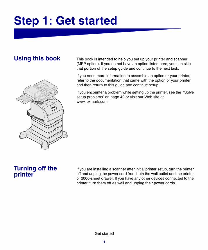
Using this book This book is intended to help you set up your printer and scanner (MFP option). If you do not have an option listed here, you can skip that portion of the setup guide and continue to the next task.
If you need more information to assemble an option or your printer, refer to the documentation that came with the option or your printer and then return to this guide and continue setup.
If you encounter a problem while setting up the printer, see the “Solve setup problems” on page 42 or visit our Web site at www.lexmark.com.
Turning off the printer
If you are installing a scanner after initial printer setup, turn the printer off and unplug the power cord from both the wall outlet and the printer or 2000-sheet drawer. If you have any other devices connected to the printer, turn them off as well and unplug their power cords.
2
Get started
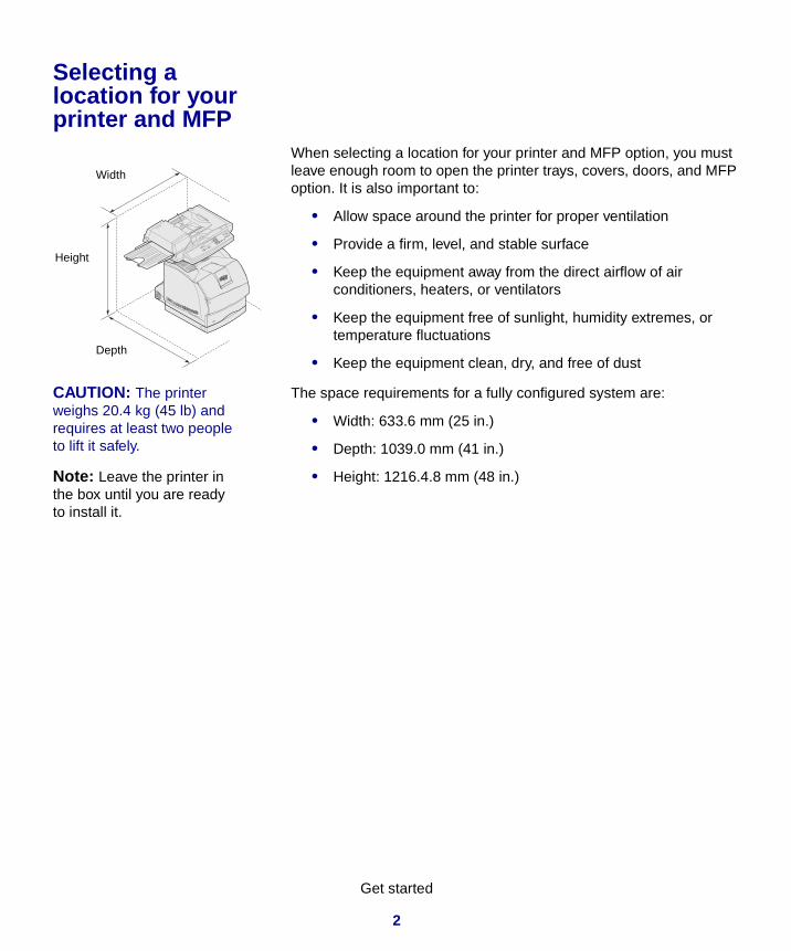
Selecting a location for your printer and MFP
When selecting a location for your printer and MFP option, you must leave enough room to open the printer trays, covers, doors, and MFP option. It is also important to:
• Allow space around the printer for proper ventilation
• Provide a firm, level, and stable surface
• Keep the equipment away from the direct airflow of air conditioners, heaters, or ventilators
• Keep the equipment free of sunlight, humidity extremes, or temperature fluctuations
• Keep the equipment clean, dry, and free of dust
CAUTION: The printer weighs 20.4 kg (45 lb) and requires at least two people to lift it safely.
The space requirements for a fully configured system are:
• Width: 633.6 mm (25 in.)
• Depth: 1039.0 mm (41 in.)
Note: Leave the printer in the box until you are ready to install it.
• Height: 1216.4.8 mm (48 in.)
Width
Height
Depth

3
Get started
Customizing your MFP option
You can customize your MFP with various input and memory options.
The printer base provides stability when configuring the printer plus input options. Configurations are limited to: 1) three 250-sheet drawers, 2) three 500-sheet drawers or any combination of three drawers, 3) a 2000-sheet drawer, 4) a 2000-sheet drawer and two 250-sheet drawers, or 4) a 2000-sheet drawer and a 500-sheet drawer. Any of the listed configurations can include a duplex unit.
Note: Leave all components and hardware in the boxes until you are ready to install them.
Check the boxes you received to make sure you have all the necessary components for the configuration you ordered.
You may want to arrange the boxes in the order the components are assembled. You can use the illustrated configurations to help lay out your boxes.
Printer, scanner shelf, and scanner
Duplex unit, printer, scanner shelf, and scanner
Caster base, two 500-sheet drawers, duplex unit, printer, scanner shelf, and scanner
Caster base, three 500-sheet drawers, duplex unit, printer, scanner shelf, and scanner
Caster base, 2000-sheet drawer, two 250-sheet drawers, duplex unit, printer, scanner shelf, and scanner
Caster base, 2000-sheet drawer, printer, scanner shelf, and scanner
Caster base, 500-sheet drawer, duplex unit, printer, scanner shelf, and scanner
Note: Additional information about furniture options is available on our Lexmark Web site at www.lexmark.com/US/products/products_supplies.
Caster base, 2000-sheet drawer, duplex unit, printer, scanner shelf, and scanner

4
Assemble paper handling options
Step 2: Assemble paper handling options
CAUTION: If you are using a 2000-sheet drawer, a duplex unit with one or more input drawers, or more than one 500-sheet drawer, you must use either a printer stand or a caster base.
If you purchased a printer stand, follow the assembly instructions provided with the stand, and then return to Step 2: “Assemble paper handling options” in this book.
The caster base is used when placing your MFP on the floor. It provides mobility and a stable platform for your MFP. There are different assembly instructions for use with a 2000-sheet drawer, 500-sheet drawer, or a 250-sheet drawer.
Preparing the caster base
1 Remove all items from the caster base carton.
2 Remove and group the machine screws, washers, stabilizer screws, and posts from the hardware bag.
CAUTION: The correct stabilizer screws must be installed in each optional drawer and the duplex unit to secure the printer and options together.
3 Determine which screws you need for your configuration and place the other screws into the bag.
• The six long screws (1) are used with three 500-sheet drawers. (two with each 500-sheet drawer)
• The six short screws (2) are used with the 2000-sheet drawer or the 250-sheet drawers.
• The two long posts (3) are used with the duplex unit.• The two short posts (4) are used when a duplex unit is not
available.• The two long machine screws (5) are used with the
2000-sheet drawer.• The two short machine screws (6) are not used with this
scanner.
Depending on your configuration, some of the stabilizer screws and posts will not be used.
4 If you have a 2000-sheet drawer, place a lock washer and flat washer on each of the two long machine screws (5).

5
Assemble paper handling options
5 Place power adapter bracket (1) aside for later use. The other power adapter bracket is not used with this scanner and can be discarded.
Note: Be sure to set up the items in the order listed in the table.
Use the following table to locate the instructions you need to set up your printer and the paper handling options you purchased.
Attaching the caster base to the 2000-sheet drawer
1 Remove and inventory all items from the 2000-sheet drawer carton.
• 2000-sheet drawer• Decals• 16 AWG power cord• Jumper cord
2 Place the decals, 16 AWG power cord, and jumper cord aside for later use.
3 Remove the two screws inside the 2000-sheet drawer pockets.
If you have difficulty lifting the screws from the pockets, you can wait until the next step when you turn the drawer over, then the screws should fall out.
Topic Go to page...
Attaching the caster base to the 2000-sheet drawer 5
Assembling the caster base for the 500 or 250-sheet drawer
8
Installing the duplex unit 11
Positioning the printer 12

6
Assemble paper handling options
4 Turn the 2000-sheet drawer over so the bottom side is up.
5 Remove the four screws and rubber feet from the bottom of the 2000-sheet drawer.
Use a number 2 Phillips screwdriver to remove the screws and install the caster base.
6 Place the caster cover on the bottom of the 2000-sheet drawer.
7 Place the frame assembly inside the caster cover.
Drawer bottom
Front

7
Assemble paper handling options
8 Insert the two long machine screws from the caster base hardware bag through the screw holes of the frame assembly and the caster cover, and then into the holes in the bottom of the 2000-sheet drawer.
Each screw goes through a lock washer, then a flat washer, then through the frame assembly and cover.
9 Tighten the screws.
CAUTION: The caster and 2000-sheet drawer weighs 22.2 kg (49 lb) and requires at least two people to lift it safely.
10 Have someone help you lift and turn the assembled 2000-sheet drawer and caster base right side up and place it on the floor.

8
Assemble paper handling options
Installing screws in the 2000-sheet drawer
1 Insert two short stabilizer screws (2) into the pockets of the 2000-sheet drawer.
2 Tighten the screws securely.
3 If you have a duplex unit, go to “Installing the duplex unit” on page 11 otherwise, go to “Positioning the printer” on page 12.
Assembling the caster base for the 500 or 250-sheet drawer
1 Remove the caster cover, screws, and frame assembly from the caster box, and place the bag of screws aside for later use.
2 Place the frame assembly on the floor.
3 Align and place the caster cover on the frame assembly.
4 Place the caster base in the location you have chosen for your MFP.
9
Assemble paper handling options
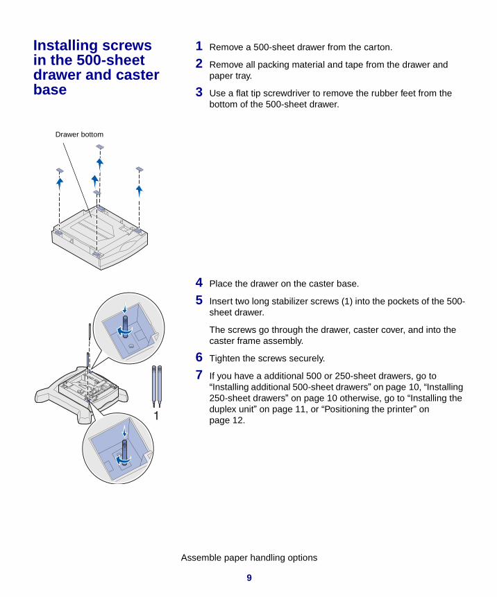
Installing screws in the 500-sheet drawer and caster base
1 Remove a 500-sheet drawer from the carton.
2 Remove all packing material and tape from the drawer and paper tray.
3 Use a flat tip screwdriver to remove the rubber feet from the bottom of the 500-sheet drawer.
4 Place the drawer on the caster base.
5 Insert two long stabilizer screws (1) into the pockets of the 500-sheet drawer.
The screws go through the drawer, caster cover, and into the caster frame assembly.
6 Tighten the screws securely.
7 If you have a additional 500 or 250-sheet drawers, go to “Installing additional 500-sheet drawers” on page 10, “Installing 250-sheet drawers” on page 10 otherwise, go to “Installing the duplex unit” on page 11, or “Positioning the printer” on page 12.
Drawer bottom

10
Assemble paper handling options
Installing additional 500-sheet drawers
1 Remove a 500-sheet drawer from the carton.
2 Remove all packing material and tape from the drawer and paper tray.
3 Use a flat tip screwdriver to remove the rubber feet from the bottom of the 500-sheet drawer.
4 Place the drawer on top of the previously installed drawer.
Make sure they lock together securely.
5 Insert two long stabilizer screws (1) into the pockets of the 500-sheet drawer.
The screws go through the drawer and into the top of the screws of the previously installed drawer.
6 Tighten the screws securely.
7 Follow steps 1 through 6 to install another 500-sheet drawer.
Installing 250-sheet drawers
1 Remove a 250-sheet drawer from the carton.
2 Remove all packing material and tape from the drawer and paper tray.
3 Use a flat tip screwdriver to remove the rubber feet from the bottom of the 250-sheet drawer.Drawer bottom

11
Assemble paper handling options
4 Place the drawer on top of the previously installed drawer or caster base.
5 Insert two short stabilizer screws (2) into the pockets of the 250-sheet drawer.
The screws go through the drawer and into the top of the screws of the previously installed drawer or into the caster frame assembly.
6 Tighten the screws securely.
Installing the duplex unit
1 Remove the duplex unit from the carton.
2 Remove all packing material and tape.
3 Use a flat tip screwdriver to remove the rubber feet from the bottom of the duplex unit.
12
Assemble paper handling options
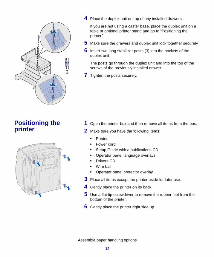
4 Place the duplex unit on top of any installed drawers.
If you are not using a caster base, place the duplex unit on a table or optional printer stand and go to “Positioning the printer.”
5 Make sure the drawers and duplex unit lock together securely.
6 Insert two long stabilizer posts (3) into the pockets of the duplex unit.
The posts go through the duplex unit and into the top of the screws of the previously installed drawer.
7 Tighten the posts securely.
Positioning the printer
1 Open the printer box and then remove all items from the box.
2 Make sure you have the following items:
• Printer• Power cord• Setup Guide with a publications CD• Operator panel language overlays• Drivers CD• Wire bail• Operator panel protector overlay
3 Place all items except the printer aside for later use.
4 Gently place the printer on its back.
5 Use a flat tip screwdriver to remove the rubber feet from the bottom of the printer.
6 Gently place the printer right side up.

13
Assemble paper handling options
7 Complete steps a and b if your configuration does not include a duplex unit.
a Insert the two short stabilizer posts (4) into the top of the stabilizer screws that were previously installed in the optional drawer.
b Tighten the posts securely.
CAUTION: The printer weighs 20.4 kg (45 lb) and requires at least two people to lift it safely.
8 Lower the printer onto the duplex unit, optional drawer, table, or printer cabinet.
9 Make sure the printer and duplex unit lock together securely.
10 If you have memory or network options to install, go to “Installing printer memory and network options” on page 14 otherwise, go to “Removing the print cartridge packaging” on page 17.
14
Assemble paper handling options
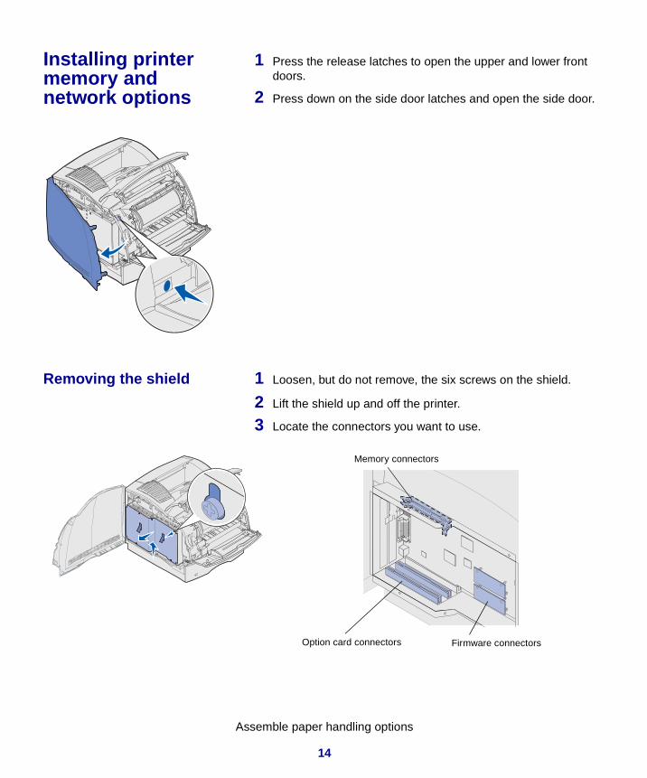
Installing printer memory and network options
1 Press the release latches to open the upper and lower front doors.
2 Press down on the side door latches and open the side door.
Removing the shield 1 Loosen, but do not remove, the six screws on the shield.
2 Lift the shield up and off the printer.
3 Locate the connectors you want to use.
Memory connectors
Option card connectors Firmware connectors

15
Assemble paper handling options
Installing memory 1 Unpack the memory option.
2 Open both latches on the connector.
3 Push the memory card firmly into the connector until it snaps into place.
Installing a firmware card
1 Locate the holes on the system board near the option card connectors.
2 Unpack the firmware card.
3 Holding the firmware card by its sides, align the two pins on the card with the holes on the system board.
4 Push in until the firmware card is firmly in place.
Installing an option card 1 Locate the card connectors on the system board. If you are installing only one card, install it in connector 1.
2 Locate the two screws on the back of the printer that attach the metal plate to the slot.
3 Remove and save the two screws, and then remove and discard the plate.
4 Unpack the card.
5 Align the connection points on the card with the connector on the system board and push the card firmly into the system board connector.

16
Assemble paper handling options
6 Insert the two screws saved from the metal plate (or the extra screws shipped with the card).
7 Tighten the screws to secure the card.
Reattaching the shield and closing the doors
1 Align the three keyholes on the shield with the screws.
2 Place the shield onto the screws and then slide the shield down.
3 Tighten all six screws.
4 Close the side door.
5 Close the upper and lower front doors.

17
Set up the printer
Step 3: Set up the printer
Removing the print cartridge packaging
1 Open the printer upper front door.
2 Pull the print cartridge up and out.
3 Remove the tabs and packaging from the cartridge.
4 Reinsert the print cartridge into the printer.
The print cartridge will drop down and snap into place.
5 Close the upper front door.
18
Set up the printer
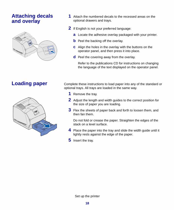
Attaching decals and overlay
1 Attach the numbered decals to the recessed areas on the optional drawers and trays.
2 If English is not your preferred language:
a Locate the adhesive overlay packaged with your printer.
b Peel the backing off the overlay.
c Align the holes in the overlay with the buttons on the operator panel, and then press it into place.
d Peel the covering away from the overlay.
Refer to the publications CD for instructions on changing the language of the text displayed on the operator panel.
Loading paper Complete these instructions to load paper into any of the standard or optional trays. All trays are loaded in the same way.
1 Remove the tray.
2 Adjust the length and width guides to the correct position for the size of paper you are loading.
3 Flex the sheets of paper back and forth to loosen them, and then fan them.
Do not fold or crease the paper. Straighten the edges of the stack on a level surface.
4 Place the paper into the tray and slide the width guide until it lightly rests against the edge of the paper.
5 Insert the tray.

19
Set up the printer
Attaching the printer cables
1 Connect the printer to a LAN drop or hub using standard cabling that is compatible with your network.
2 Attach the printer power cord to the connector on the side of the printer.
3 If you have a 2000-sheet drawer, connect the printer power cord into the socket on the back of the 2000-sheet drawer. Otherwise go to step 5.
4 Connect the 16 AWG power cord to the socket on the back of the 2000-sheet drawer.
5 Connect the 16 AWG power cord (or printer power cord if you do not have a 2000-sheet drawer) to a properly grounded outlet.
Verifying printer setup
1 Turn on the printer.
After the printer completes its internal tests, the Ready message is displayed.
Note: If you see a message other than Ready on the display, refer to the printer publications CD for instructions on clearing the message.
2 Turn on your computer and any other peripherals.
Printing a menu settings page
1 Press Menu until you see Utilities Menu, and then press Select.
2 Press Menu until you see Print Menus, and then press Select to print the page. The message Printing Menus appears on the display.
3 Verify the options you installed are correctly listed under “Installed Features” and “Printer Information.”
Network cable
Printer power cord

20
Set up the printer
Printing a network setup page
1 Press Menu until you see Utilities Menu, and then press Select.
2 Press Menu until you see Print Net Setup, and then press Select to print the page.
Save the network setup page after it prints. You will use it later.
Printing Quick Reference information
Information about using the printer and clearing jams is included on the publications CD that shipped with your printer documentation.
We recommend you print this information and store it in a convenient location near the printer.
1 Press Menu until you see Utilities Menu, and then press Select.
2 Press Menu until you see Quick Reference, and then press Select.
3 Press Menu until you see the topic you want to print, and then press Select.
4 Repeat steps 1 through 3 to print the other pages.
Configuring for TCP/IP
Assigning a printer IP address
If your network is using DHCP, an IP address is automatically assigned after you connect the network cable to the printer.
1 Look for the address under the “TCP/IP” heading on the network setup page you printed earlier.
2 Go to “Verifying the IP settings” on page 21 and begin with step 2.
If your network is not using DHCP, then you must manually assign an IP address to the printer.
1 Press Menu until you see Network Menu, and then press Select.
2 Press Menu until you see Standard Network, and then press Select.

21
Set up the printer
3 Press Menu until you see Std Net Setup (or Network 1 Setup or Network 2 Setup), and then press Select.
4 Press Menu until you see TCP/IP, and then press Select.
5 Press Menu until you see Set IP Address, and then press Select.
6 Change the address by pressing Menu to increase or decrease each number. Press Select to move to the next segment. Press Select when you are finished.
The message Saved appears briefly.
7 Press Menu until you see Set IP Netmask, and then press Select.
8 Repeat step 6 to set the IP Netmask.
9 Press Menu until you see Set IP Gateway, and then press Select.
10 Repeat step 6 to set the IP Gateway.
11 When you are finished, press Go to return the printer to the Ready state.
Verifying the IP settings 1 Print another network setup page. Look under the “TCP/IP” heading and make sure the IP address, netmask, and gateway are what you expected.
See “Printing a network setup page” on page 20 if you need help.
Note: On Windows computers, click Start Programs Command prompt (or Accessories Command prompt if using Windows 2000).
2 Ping the printer and verify that it responds. For example, at a command prompt on a network computer type ping followed by the new printer IP address (for example, 192.168.0.11):
ping xxx.xxx.x.xx
If the printer is active on the network, you receive a reply.
Attaching the scanner shelf
1 Turn the printer off.
2 Unplug the 16 AWG power cord or printer power cord from the grounded outlet.

22
Set up the printer
3 Remove the top cover or any previously installed print media handling options from the printer.
You will not need the cover when the scanner shelf is attached. Store the cover, it will be needed if you remove the shelf.
4 Align and insert the scanner shelf mounting brackets into the slots on top of the printer.
5 Make sure the scanner shelf is positioned securely.
6 Place the tips of the wire bail into the ends of the plastic brackets so that the bail curves downward.
The wire bail came with the printer and rests in the standard output bin when installed.

23
Install the scanner
Step 4: Install the scanner
1 Open the scanner box and then remove all items from the box except the scanner.
2 Make sure you have the following items:
• Scanner• Paper tray• Y-line power cord• Power adapter• Scanner cable• Setup Guide• Drivers CD• Pad assembly (store for later use, not used during setup)
3 Place all items except the scanner aside for later use.
4 Remove the scanner from the box and place it on a flat, level surface.
5 Locate the lock switch on the bottom of the scanner.
6 Push the switch up to the unlocked position.
7 Place the scanner on the scanner shelf.
8 Insert two thumbscrews attached to the bottom of the scanner shelf into the bottom of the scanner and tighten securely.

24
Install the output tray and raise the feed tray
Step 5: Install the output tray and raise the feed tray
Note: The automatic document feeder and the feed tray are attached to the scanner before it is shipped.
1 Attach the output paper tray to the automatic document feeder.
Make sure the tray snaps into place and lies flat.
2 Lift the feed tray and raise the support bar to an upright position.
Feed tray
Output paper tray
Automatic document feeder
Support bar

25
Attach cables and power cords
Step 6: Attach cables and power cords
Attaching cables to the printer
Connect the printer to the telephone line, network, and MFP.
Note: Germany: Use only the German TAE type F adapter shipped with this product because it contains a billing tone filter. The adapter is designed only for the F connector of the German wall outlet. This must be the only device attached to the NFN wall receptacle. Switzerland: Use only the Swiss adapter shipped with this product because it contains a billing tone filter.
1 Connect the RJ-11 telephone fax line cable into the fax modem port on the back of the print server installed in your printer.
2 If you received a telephone adapter specifically designed for use in your country, attach the telephone adapter to the telephone fax line cable and plug the fax line cable into the phone line outlet.
3 Connect the Ethernet cable into the Ethernet network port on the back of the print server installed in your printer.
4 Connect the scanner cable to the printer, but do not turn the power on yet.
Scanner cable
Ethernet network cable
Telephone fax line cable (RJ-11)

26
Attach cables and power cords
Attaching cables to the scanner
1 Connect the scanner cable to the scanner.
2 Connect the power adapter cord to the scanner.
3 Connect the Y-line power cord to the power adapter.
4 Place the power adapter bracket into the slots on the caster base and then place the power adapter into the bracket.
5 Remove the printer power cord from the printer.
6 Connect the Y-line power cord to the printer.
7 Connect the printer power cord to the Y-line cord.
8 Connect the printer power cord or the 2000-sheet 16 AWG power cord to a properly grounded outlet, but do not turn the power on yet.
Printer power cord
Power adapter bracket
Y-line power cord
Scanner cable
Power adapter
Printer power cord
Power adapter bracket
Y-line power cord
Scanner cable
Power adapter

27
Turn on the scanner and printer
Step 7: Turn on the scanner and 7: Turn on the scanner and printer
Performing a power up sequence
1 If you are using a print server with a modem, plug the telephone fax line cable into the phone line outlet.
2 If you disconnected the Ethernet network cable from the print server, reconnect it.
3 Plug the printer power cord or 2000-sheet 16 AWG power cord into a properly grounded outlet.
4 Turn on the scanner.
5 Turn on the printer.On/off switch

28
Turn on the scanner and printer
6 Wait for the MFP to initialize. When the scanner comes on, there is a short wait cycle while the firmware is initialized. Please Set Date/Time is displayed on the first line of the MFP control panel and “Please Wait...” is displayed on the second line.
Do not turn off the printer or unplug the scanner until the Please Wait... message disappears from the control panel.
Hardware setup is now complete. You are ready to configure the MFP.
First time setup MFP panel: When initialization is completed, the Please Wait... message disappears. The Please Set Date/Time prompt indicates that you need to set required fax information.
Restart MFP panel: When you restart the MFP, a Please Wait... message appears on the second line of the control panel. When initialization is completed, the MFP control panel displays the current time and date, plus the Ready message.
Printer operator panel
Printer panel: When you turn on your printer after installing the MFP, you may see the message on the left. The Analog Fax option is disabled unless there is a minimum 24MB of printer memory.
If you receive this message, install additional printer memory to meet or exceed the 24MB requirement.
Please Set Date/Time
Please Wait...
Please Wait...
24MB of memory required for Fax...

29
Turn on the scanner and printer
Understanding the scanner indicator lights
There are three indicator lights on top of the scanner. Each represents a different mode.
Yellow Power indicator. When lit, power is on.
Green Scanner is ready, but not in Power Saver mode. If green and red lights are off and yellow light is on, scanner is in Power Saver mode. Pressing a button removes the scanner from Power Saver mode. When the scanner is reactivated, there is a short warm-up period.
Red Error. When lit, an error is indicated and scanning is stopped. Check for possible paper jams or other paper feed errors. Refer to the user documentation on the CD.
Indicator lights

30
Change your default copy settings
Step 8: Change your default copy settings
A number of copy settings are available for customizing the MFP output to suit your needs. Some settings or values are displayed only if a specific option is installed on your printer.
The indicator light next to the value on the control panel illuminates to indicate the current setting. When you select a new setting, the light changes to the selected setting to identify it as the current default. These settings remain active until new ones are selected or the factory defaults are restored.
There are three methods to change the copy default settings for your MFP. They are 1) manually entering the information through the MFP control panel and operator panel, 2) using your browser to access the MFP IP address and then entering the Configure menu, or 3) using MarkVision™ Professional to access the MFP IP address and enter the Configure menu.
Manually changing settings
1 On the MFP control panel, press the appropriate buttons to change the Content, Copy Media, Duplex, or other settings to the default options you want.
Note: You can change the copy settings for individual jobs by changing settings on the control panel but not entering the Copy menu to save the settings. The MFP returns the settings to the default value after approximately 1 minute.
2 After you make your selections, press Menu until Copy menu appears.
3 Press Menu until Copy menu =Save appears, and then press Select.
4 Press Go.
Ready is displayed.

31
Change your default copy settings
Using your browser
1 Type the IP address of the MFP in the URL field of your browser (for example, http://192.168.236.24), and then press Enter.
2 Click Configuration.
Note: Many of these settings depend on the printer, options, and scanner combination you have.
3 Select Copy Setup from the MFP menu.
The Copy Setup page has the following menu items available:
4 Select the menu item for the setting you want to change.
5 Select the new setting and click Submit.
6 Repeat steps 1 through 5 to change additional settings.
Using MarkVision Professional
MarkVision Professional is a printer management utility on the drivers CD.
Note: Instructions for installing MarkVision Professional are in the CD booklet shipped with the drivers CD.
After installing MarkVision Professional, you can do an IP search to find the MFP containing the print server and go to the Copy tab to set the required information. Click Configure TCP/IP, and launch the TCP/IP address manager.
Follow the instructions on the screen, and then save your settings before closing MarkVision Professional.
• Content • Copy Media
• Paper Saver • N-up frame
• Duplex • Finishing
• Original Size • Copy Size
• Scaling • Default Darkness
• Output Bin • Number of Copies
• Factory Defaults

32
Set send and receive fax information
Step 9: Set send and receive fax information
Understanding FCC fax requirements
During fax setup, you must assign some basic information. The Telephone Consumer Protection Act of 1991 requires all outgoing faxes to contain the following information in a margin at the top or bottom of each transmitted page, or on the first page of the transmission:
Note: See “Electronic Emission notices” on page 48 and “Telecommunications notices” on page 48 for more FCC information.
• Date and time (date and time fax is sent)
• Station name (identification of the business, other entity, or individual sending the message)
• Station number (telephone number of the sending fax machine, business, other entity, or individual)
Note: If you do not have a TCP/IP environment, you must use the MFP control panel to set your basic fax information.
There are three methods to enter your fax setup information. They are 1) manually entering the information through the MFP control panel, 2) using your browser to access the MFP IP address and then entering the Configure menu, or 3) using MarkVision Professional to access the MFP IP address and enter the Configure menu.
Use the following table to find the instructions for the method you want to use.
Method Page
Performing manual fax setup 33
Performing browser fax setup 34
Using MarkVision Professional to set fax information 35

33
Set send and receive fax information
Performing manual fax setup
You can quickly change menu settings from the MFP control panel by pressing Menu and then selecting the menu for the area you want to change.
To manually enter the fax setup information:
1 On the control panel, press Menu repeatedly until you see Fax Quick Setup, and then press Select.
2 When Country/Zone appears, use Menu to find your country and time zone (for example, Eastern), and then press Select to save your choice.
3 Set the current date and time:
If the correct date and time appear on the display, press Return to go to the next menu item.
If the default date and time appear (1900-01-01 15:35) on the display, use the numeric keypad to change the numbers in each field. After the date and time are set, the next menu item appears.
4 When you see Station Name, enter your name or company name using the numeric keypad on the panel.
5 Press Return when you have finished entering your Station Name. SAVED briefly appears.
6 When you see Station Number, enter your fax phone number using the numeric keypad on the panel.
7 Press Return after entering your Station Number. SAVED briefly appears. After the last menu item has been entered, Setup Complete appears.

34
Set send and receive fax information
Performing browser fax setup
After the IP address is set, use your browser to set the required fax information. You can also configure the MFP to route faxes received through the fax modem port on the print server (with modem) to an output bin on your printer.
Note: Configuration is a task usually done by a network administrator. If you are prompted for a password during the following instructions, see your network administrator for help.
1 Type the IP address of the MFP in the URL field of your browser (for example, http://192.168.236.24), and then press Enter.
2 Click Configuration.
3 Under the MFP heading, click Fax Setup.
4 Click Configuration.
If you are changing fax modes, you must click Submit before you can access the configuration page.
Note: During printer power up, if the print server is configured to use Network Time Protocol (NTP) time, the current date and time are provided. However, you must set the time zone to get the correct time.
5 Enter the required FCC information:
• Date and time (current date and time)• Station name (personal name or company name)• Station number (fax phone line number)
6 Select the Time Zone, such as Eastern (USA and Canada, Eastern Standard Time). This sets the required information.
7 Set your options for Fax storage, Output bin, Rings to Answer, and so on.
For a complete list of receive fax options, refer to the online documentation on the MFP CD.
8 After you finish entering the information, click Submit.

35
Set send and receive fax information
Using MarkVision Professional to set fax information
MarkVision Professional is a printer management utility on the drivers CD.
Note: Instructions for installing MarkVision Professional are in the CD booklet shipped with the drivers CD.
After installing MarkVision Professional, you can do an IP search to find the MFP containing the print server and go to the Fax tab to set the required information. Click Configure TCP/IP, and launch the TCP/IP address manager.
Follow the instructions on the screen, and then save your settings before closing MarkVision Professional.
Changing optional settings
Optional settings such as setting up a fax transmission log, creating permanent fax destinations, and enabling the fax server function can be changed through the MFP control panel, your browser, or MarkVision Professional. The following optional settings are explained using the browser method.
Setting up a fax transmission log
When you send or receive a fax, an entry of the activity is recorded in a file. You can print this file when you want, or specify that it be printed automatically.
To set the fax transmission log options:
1 Type the IP address of the MFP in the URL field of your browser, and then press Enter.
2 Click Configuration.
Note: For a complete list of fax log options, refer to the online information on the MFP CD.
3 Under the MFP heading, click Fax Setup.
4 Click Configuration.
5 Set your options for printing the transmission logs and output bins.
6 When you finish, click Submit.
See your printer documentation for supported paper sizes, paper types, and output bins.

36
Set send and receive fax information
Creating permanent fax destinations
Instead of entering the phone numbers of fax recipients each time you send a fax, you can create permanent fax destinations that appear on the MFP control panel.
Note: Once permanent fax destinations are created, they become accessible on the MFP control panel. Press Fax/Scan mode repeatedly until SCAN → Fax appears in the control panel display. Press Menu to move through the list.
1 Type the IP address of the MFP in the URL field of your browser, and then press Enter.
The destinations you create here are stored only on this MFP.
2 Click Configuration.
3 Under the MFP heading, click Manage Destinations.
4 Click Fax Destinations Setup.
5 Enter a unique name for the fax recipient and specify their fax number (for example, John_Acct 555-1212).
Note: You can create a group fax distribution list by creating a permanent destination containing multiple recipient fax numbers. Separate each entry with a comma. Make sure you assign a unique name that identifies the destination as a group fax.
6 Assign a shortcut number (1–245).
Assigning a shortcut lets you press #, and then the assigned number to activate your scan. If you enter a shortcut number already in use, you are prompted to select another number.
7 Click Submit.
Enabling fax server function
When this mode is enabled, instead of using the modem to send outgoing faxes, the phone number is incorporated into the e-mail address of the Fax Server and an e-mail is sent to the fax server with the fax image as an attachment.
Note: Enabling the fax server function disables the analog fax send function.
1 Type the IP address of the MFP in the URL field of your browser (for example, http://192.168.236.24), and then press Enter.
2 Click Configuration.
3 Click Fax Setup under the MFP menu.
Note: If Fax Server is already selected, press Configuration.
4 Select Fax Server, and then click Submit.
5 Enter the settings for Fax Server.

37
Set up network scanning
Step 10: Set up network scanning
Note: The control panel will not display a Scan to... menu item unless the menu item has been configured.
In addition to making copies and sending faxes, the MFP lets you scan documents and send them to designated destinations on your network.
There are three scan to network modes:
• Scan to Profile (for single use scan jobs such as one time scan to e-mail or scanning documents back to your workstation)
• Scan to e-mail (to a permanent destination)
• Scan to FTP (to an FTP server)
PerformingScan to Network General Setup
Configure default scan job settings
You can configure some default scan job settings that preset the MFP control panel formats for all Scan to e-mail and Scan to FTP jobs.
1 Type the IP address of the MFP in the URL field of your browser (for example, http://192.168.236.24), and then press Enter.
2 Click Configuration.
3 Under the MFP heading, click Scan to Network General Setup.
Note: After you create a list of permanent destinations, it becomes available in the MFP control panel; these default settings are active choices for your typical scan job.
4 Set your default network scan settings.
It is a good idea to base these settings on the most common types of originals you will be scanning.
These defaults can be overridden by changing the settings on the MFP control panel just before scanning.
5 Click Submit.

38
Set up network scanning
Performing Scan to E-mail General Setup
Specify SMTP gateway and other E-mail settings
1 Type the IP address of the MFP in the URL field of your browser, and then press Enter.
2 Click Configuration.
3 Under the MFP heading, click Scan to E-mail General Setup.
Note: You may want to use the network administrator’s address as the default address. When an e-mail cannot be sent, notification is returned to this address.
4 Specify the SMTP gateway of your network or internet service provider, plus your e-mail address for the reply line of the message.
5 Enter a subject (descriptive name) and a generic message suitable for use on all Scan to e-mail jobs.
This information appears on all e-mail scanned to permanent e-mail destinations.
6 To store scanned documents on a Web site and send only a Web link in the e-mail, complete the Web Link section.
7 After entering your choices, click Submit.
Creating permanent e-mail destinations
Create a separate recipient entry for each destination and give them unique names easily identified in the destinations list.
1 Type the IP address of the MFP in the URL field of your browser, and then press Enter.
2 Click Configuration.
3 Under the MFP heading, click Manage Destinations.
Note: Before you create a destination, check the list at the bottom of the Web page. Make sure your recipient is not already listed.
4 Click E-mail Destinations Setup.
5 Enter a unique name for the destination.
6 Enter the destination e-mail address.
7 Specify to send the scanned document either as an Attachment or as a Web Link.
8 Select scan type and resolution.

39
Set up network scanning
Note: You can rapidly find your e-mail recipient by pressing # and entering the shortcut number on the MFP control panel.
9 Assign a shortcut number (1–245) to the destination (optional).
10 Click Add/Modify. This new destination is now available for selection from the MFP control panel menu.
Creating permanent FTP destinations
Create a separate recipient entry for each destination and give them unique names easily identified in the destinations list.
1 Type the IP address of the MFP in the URL field of your browser, and then press Enter.
2 Click Configuration.
3 Under the MFP heading, click Manage Destinations.
Note: Before you create a destination, check the list at the bottom of the Web page. Make sure your recipient is not already listed.
4 Click FTP Destinations Setup.
5 Enter a unique name for the destination.
6 Enter Server name, Log-in, Password, and Filename.
7 Select scan type and resolution.
Note: You can rapidly find your FTP recipient by pressing # and entering the shortcut number on the MFP control panel.
8 Assign a shortcut number (1–245) to the destination (optional).
9 Click Add/Modify. This new destination is now available for selection from the MFP control panel menu.

40
Verify MFP setup
Step 11: Verify MFP setup
Making a test copy Copy mode is the default setting of the control panel.
1 Make sure the Ready message is displayed.
2 Place your original document in the scanner.
3 Press Go/Send to send a copy to your printer.
Sending a test fax Send a one page test fax to someone and ask for feedback.
Note: If Send/Fax is disabled, this option does not appear.
1 Press Fax/Scan Mode once. Enter Phone # is displayed on the MFP control panel.
2 Use the numeric keypad on the control panel and enter the phone number of the person receiving the fax.
3 Place your original document in the scanner.
4 Press Go/Send to send a fax.
Testing scan to network
Test your scan to network functions by creating Scan Profiles or scanning to permanent destinations.
You can only test the scan to network functions that you configured during setup. For example, to test Scan to E-mail, you must have created at least one permanent e-mail destination. Otherwise, SCAN → EMAIL does not appear as a scan to network mode in the MFP control panel.

41
Distribute MFP user instructions
Step 12: Distribute MFP user instructions
Finding user instructions
MFP online documentation includes helpful instructions for making copies, sending faxes, and scanning documents to e-mail, FTP destinations, or back to your computer.
To view the available information on the MFP CD, click View Documentation, and then select your MFP.
Distributing user information
Here are several ways to distribute MFP information:
• Print copies of each set of user instructions stored on the MFP CD, and manually deliver them to users.
• Copy the PDF containing the user instructions and store it in a convenient common location on your network or Intranet. The PDF is stored in the Pubs directory on the MFP CD.
• Browse the Lexmark™ Web site (www.lexmark.com) and access the information there. Save the URL and send the link to your MFP users.
Limiting MFP use MFP Job Accounting can be configured to require users to enter an authorized number or select an authorized name to unlock the control panel.
Detailed instructions are on the MFP CD. Click View Documentation Use MFP More MFP Configuration.

42
Solve setup problems
Solve setup problems
Getting more help Launch the MFP CD, and then click Contact Lexmark for a complete list of phone numbers and Web sites.
Problem Solution
Ready message not displayed The control panel and the printer are not talking to each other, or the printer or scanner may be turned off.
1 Turn the printer off, and then back on.
2 Turn the printer and scanner off. Make sure all cables and cords are connected, and then power up in the correct order.
Note: Remember to turn the scanner on before turning on the printer.
Control panel buttons not responding Make sure the printer is turned on.
Note: Remember to turn the scanner on before turning on the printer.
Scanner is not working 1 Make sure the scanner is unlocked. See step 5 on page 23.
2 Turn printer and scanner off. Make sure all cables and cords are connected, and then power up in the correct order.
Note: Remember to turn the scanner on before turning on the printer.
Test document did not print 1 Verify that each electrical outlet has power.
2 Make sure all cables and line cords are properly seated.
3 Restart the copy job.
Unable to send or receive faxes 1 Make sure the telephone fax line cable is properly connected to the fax modem port on the print server and to the fax phone outlet.
2 Repeat the fax setup. See “Set send and receive fax information” on page 32.
3 Refer to the online information on the MFP CD. Click View Documentation Use MFP Solving fax problems.
Network scanning modes (SCAN → PROFILE, SCAN → EMAIL, or SCAN → FTP) do not appear in the control panel
Scan to network modes must be configured in order to show up in the MFP control panel. See “Set up network scanning” on page 37 for detailed instructions.

43
Maintain your scanner
Maintain your scanner
Clearing a paper jam
1 Open the automatic document feeder.
2 Carefully pull out the jammed paper.
3 Close the automatic document feeder.

44
Maintain your scanner
Cleaning the automatic document feeder
The scanner parts can become contaminated with ink, toner particles, or paper coatings. Clean the scanner feed rollers if documents do not feed smoothly or easily, or if several documents feed at one time.
1 Turn off and disconnect the power to the scanner.
2 Open the automatic document feeder.
3 Wet a clean, lint-free cloth or cotton swab with isopropylalcohol (95%).
4 Wipe the feed rollers by moving the swab from side to side.
5 Rotate the roller forward with your finger and repeat step 4 until the entire roller is cleaned.
6 Close the automatic document feeder.
7 Reconnect the power and turn the scanner back on.
Feed rollers

45
Maintain your scanner
Cleaning the document glass
1 Open the document cover.
2 Wet a clean, lint-free cotton cloth or swab with isopropyl alcohol (95%).
3 Wipe the scanner glass and automatic document feeder area by moving the cloth or swab from side to side.
4 Close the document cover.
Glass

46
Maintain your scanner
Moving the scanner
If you need to transport the scanner, follow these instructions to relock the scanner:
Warning: Failure to lock the scan mechanism before moving the scanner can cause internal damage.
1 Open the document cover.
2 Turn the scanner on.
3 When the scanning mechanism reaches the far right side of the scanner glass, turn the scanner off.
4 Close the document cover.
5 Raise the scanner high enough to move the switch down to the locked position.

47
Maintain your scanner
Replacing the pad assembly
If you experience problems with papers double-feeding through the automatic document feeder, the pad assembly may be worn.
To replace the automatic document feeder pad:
1 Turn the scanner off.
2 Open the automatic document feeder.
3 Remove the old automatic document feeder pad assembly by squeezing and pulling out the upper part of the pad clamp.
4 Hold the upper part of the new clamp, squeeze, and place it gently in the pad holder.
5 Close the automatic document feeder.
Pad clamp

48
Notices
Notices
The following notices apply to machine type 4036-306.
The following telecommunications notices apply to those machines in which the print server is installed.
Electronic Emission noticesWarning: This is a Class A product. In a domestic environment, this product may cause radio interference, in which case the user may be required to take adequate measures.
FCC Rules -- Part 15
The print server has been tested and found to comply with the limits for a Class A digital device, pursuant to Part 15 of the FCC Rules (Federal Communications Commission).
Operation is subject to the following two conditions: (1) this device may not cause harmful interference, and (2) this device must accept any interference received, including interference that may cause undesired operation.
The FCC Class A limits are designed to provide reasonable protection against harmful interference when the equipment is operated in a commercial environment. This equipment generates, uses, and can radiate radio frequency energy and, if not installed and used in accordance with the instruction manual, may cause harmful interference to radio communications. Operation of this equipment in a residential area is likely to cause harmful interference, in which case the user will be required to correct the interference at his own expense.
The manufacturer is not responsible for any radio or television interference caused by using other than recommended cables or by unauthorized changes or modifications to this equipment. Unauthorized changes or modifications could void the user's authority to operate this equipment.
Industry Canada ICES-003
This Class A digital apparatus complies with Canadian ICES-003.
Avis de conformité aux normes d’Industrie Canada
Cet appareil numérique de la classe A respecte toutes les exigences du Règlement sur le matériel brouilleur du Canada.
Telecommunications notices
FCC rules Part 68
This equipment complies with Part 68 of the FCC Rules. A label on the back of the equipment shows its FCC registration number and ringer equivalence number (REN).Your telephone company may ask you for these numbers in order to determine how many devices may be connected to your telephone line (in most areas, no more than five). If too many RENs are assigned to your telephone line, this device may not ring in response to an incoming call. Contact the telephone company to determine the maximum RENs for your calling area. This equipment uses an RJ-11C Universal Service Order Code (USOC) jack, and is designed to be connected to the telephone network or premises wiring using a compatible jack that is FCC Part 68

49
Notices
compliant. An FCC compliant telephone cord is provided with this equipment. Refer to the setup documentation for instructions about connecting the fax telephone cable. If you experience problems with this equipment that you cannot resolve, contact Lexmark International, Inc., for repair and warranty information. If the problems are causing harm to the telephone network, the telephone company may ask you to disconnect the equipment from the network until the problem is resolved. If the equipment causes harm to the telephone network, the telephone company will notify you in advance, or as soon as possible, that temporary discontinuance of service may be required. You will also be notified of your right to file a complaint with the FCC if you believe it is necessary.The telephone company may make changes to its facilities, equipment, operations, or procedures that could affect the operation of this equipment. If this happens, the telephone company will notify you in advance so you can make necessary adjustments in order to maintain uninterrupted service.This equipment cannot be used on telephone company-provided coin service.Connection to party lines is subject to state tariffs.To avoid damage caused by lightning strikes and other electrical surges, we recommend that you install an ac surge protector in the outlet to which this device is connected.The Telephone Consumer Protection Act of 1991 makes it unlawful to send a fax unless the following information is included (1) in a margin at the top or bottom of each transmitted page, or (2) on the first page of the transmission:
• Date and time the fax is sent• Identification of the business, other entity, or
individual sending the fax• Telephone number of the sending machine
or such business, other entity, or individual
Industry Canada CS-03 notice
Notice: This equipment meets the applicable Industry Canada Terminal Equipment Technical Specifications. This is confirmed by the registration number. The abbreviation, IC, before the registration number signifies that registration was performed based on a Declaration of Conformity indicating that Industry Canada technical specifications were met. It does not imply that Industry Canada approved the equipment. The registration number is located on the equipment.
The Ringer Equivalence Number (REN) for this terminal equipment is located on the approved terminal equipment labeling. The REN assigned to each terminal equipment provides an indication of the maximum number of terminals allowed to be connected to a telephone interface. The termination on an interface may consist of any combination of devices subject only to the requirement that the sum of the Ringer Equivalence Numbers of all the devices does not exceed five.
Before installing this equipment, users should ensure that it is permissible to be connected to the facilities of the local Telecommunications Company. The equipment must also be installed using an acceptable method of connection. The customer should be aware that compliance with the above conditions might not prevent degradation of service in some situations.
A representative designated by the supplier should coordinate repairs to certified equipment. Any repairs or alterations made by the user to this equipment, or equipment malfunctions, may give the telecommunications company cause to request the user to disconnect the equipment.
Users should ensure for their own protection that the electrical ground connections of the power utility, telephone lines and internal metallic water pipe system, if present, are connected together.

50
Notices
This precaution may be particularly important in rural areas.
CAUTION: Users should not attempt to make such connections themselves, but should contact the appropriate electric inspection authority, or electrician, as appropriate.
This equipment uses the following jacks: CA11A.
European Community (EC) directives conformityThis product is in conformity with the protection requirements of EC Council directives 89/336/EEC, 73/23/EEC, and 1999/5/EC on the approximation and harmonization of the laws of the Member States relating to electromagnetic compatibility and safety of electrical equipment designed for use within certain voltage limits and on radio equipment and telecommunications terminal equipment.A declaration of conformity with the requirements of the directives has been signed by the Director of Manufacturing and Technical Support, Lexmark International, S.A., Boigny, France.
Warning: This is a Class A product. In a domestic environment, this product may cause radio interference, in which case the user may be required to take adequate measures.
This product satisfies the Class A limits of the EMC standard EN 55022 and the safety requirements of EN 60950. It is compliant with the telecommunication standard: TBR 21 for use with Telecommunication Terminal Equipment which is permitted by Council Directive 1999/5/EC of the European Parliament and of the Council relating to Radio & Telecommunications Terminal Equipment.
Network compatibility notices
This equipment has been designed, tested and found to be compliant with the essential requirements of European technical standard TBR 21 for Pan-European single terminal connection to the Public Switched Telephone Network (PSTN).
This applies to all print servers which bear the following mark:
This equipment is designed to inter-work with PSTN networks that accept analog signals.
However, due to differences between the individual PSTNs provided in different countries, the TBR 21 certification does not, in itself, give an unconditional assurance of successful operation on every PSTN network termination point. In the event of problems, you should contact your equipment supplier in the first instance.
There are currently no known interoperating difficulties for the following countries:
Using the print server in Germany
The print server requires a German billing tone filter to be installed on any line which receives metering pulses in German. Contact customer support for ordering information.
The subscriber may request that metering pulses be placed on the line, or can have them removed by calling the German network provider. Normally, metering pulses are not provided unless specifically requested by the subscriber at the time of installation.
Using the print server in Switzerland
The print server requires a Switzerland billing tone filter to be installed on all equipment used in Switzerland since metering pulses are present on
Austria Belgium Denmark Finland
France Germany Luxemburg Netherlands
Greece Iceland Ireland Italy
Portugal Sweden United Kingdom
Switzerland
Spain Norway

51
Notices
all analog lines. Contact customer support for ordering information.
South Africa telecommunications notice
This modem must be used in conjunction with an approved surge protection device when connected to the PSTN network.