Embed Size (px)
Citation preview

Operating Manual
az
GROUNDKEEPER JUMBO
GHS(-T) – 150, 180, 210
&
KMLS(-T) – 150, 180, 210
MG2290 BAF0008.1 01.09 Printed in France
Please read and follow this op-erating manual before putting
the machine into operation. Keep it in a safe place for future
use.
GB
Foreword
2 Groundkeeper Jumbo BAF0008.1 01.09
READING THE INSTRUCTION manual and adhering to it should not appear to be inconvenient and superfluous as it is not enough to hear from others and to realise that a machine is good, to buy it and to believe that now everything should work by itself. The person concerned would not only harm himself but also make the mistake of blaming the machine for the reason of a possible failure instead of himself. In order to ensure good success one should go into the mind of a thing, make himself familiar with every part of the machine and to get acquainted with its handling. Only in this way would you be satisfied both with the machine as also with yourself. To achieve this is the purpose of this in-struction manual.
Leipzig-Plagwitz 1872.

Identification data
Groundkeeper Jumbo BAF0008.1 01.09 3
Identification data
Enter the machine identification data here. You will find the identifica-tion data on the rating plate.
Machine identification number: (ten-digit)
Type: Groundkeeper Jumbo Year of manufacture: Basic weight (kg): Approved total weight (kg): Maximum load (kg):
Manufacturer's address
AMAZONE S.A. FORBACH
17, rue de la Verrerie
BP 90106
F-57602
Phone:
Fax:
E-mail:
Forbach, France
+33 (0) 3 87 84 65 70
+33 (0) 3 87 84 65 71
Spare part orders
AMAZONEN-WERKE
H. DREYER GmbH & Co. KG
Postfach 51
DE-49202
Phone:
Fax:
E-mail:
Hasbergen
+ 49 (0) 5405 501-290
+ 49 (0) 5405 501-106
Online spare parts catalogue: www.amazone.de
When ordering spare parts, always specify the (ten-digit) machine identification number.
Formalities of the operating manual
Document number: MG2290
Compilation date: 01.09
Copyright AMAZONE S.A. FORBACH, 2008
All rights reserved.
Reprinting, even of extracts, is only permitted with the approval of AMAZONE S.A. FORBACH.
Foreword
4 Groundkeeper Jumbo BAF0008.1 01.09
Foreword
Dear Customer,
You have chosen one of the quality products from our wide range of AMAZONE agricultural machinery. We thank you for your confidence in our products.
On receiving the machine, check to see if it was damaged during transport or if parts are missing. Using the delivery note, check that the machine was delivered in full including the ordered special equip-ment. Replacement will be made only if a claim is filed immediately!
Please read and follow this operating manual—in particular, the safety instructions—before putting the machine into operation. Only after careful reading will you be able to benefit from the full scope of your newly purchased machine.
Please ensure that all the machine operators have read this operating manual before they put the machine into operation.
Should you have problems or queries, please consult this operating manual or give us a call.
Regular maintenance and timely replacement of worn or damaged parts increases the lifespan of your machine.
User evaluation
Dear Reader
We update our operating manuals regularly. Your suggestions for improvement help us to create ever more user-friendly manuals. Please send your suggestions to:
AMAZONE S.A. FORBACH
17, rue de la Verrerie
BP 90106
F-57602
Phone:
Fax:
E-mail:
Forbach, France
+33 (0) 3 87 84 65 70
+33 (0) 3 87 84 65 71

Table of Contents
Groundkeeper Jumbo BAF0008.1 01.09 5
1 User information.......................................................................................... 7 1.1 Purpose of the document.................................................................................................... 7 1.2 Locations in the operating manual ...................................................................................... 7 1.3 Diagrams used ................................................................................................................... 7 2 General safety instructions ........................................................................ 8 2.1 Obligations and liability ....................................................................................................... 8 2.2 Representation of safety symbols ..................................................................................... 10 2.3 Organisational measures .................................................................................................. 11 2.4 Safety and protection equipment....................................................................................... 11 2.5 Informal safety measures.................................................................................................. 11 2.6 User training..................................................................................................................... 12 2.7 Safety measures in normal operation................................................................................ 13 2.8 Dangers from residual energy........................................................................................... 13 2.9 Maintenance and repair work, fault elimination.................................................................. 13 2.10 Constructive changes ....................................................................................................... 13 2.10.1 Spare and wear parts and aids ......................................................................................... 14 2.11 Cleaning and disposal ...................................................................................................... 14 2.12 User workstation............................................................................................................... 14 2.13 Warning symbols and other signs on the machine............................................................. 14 2.13.1 Positioning of warning symbols and other labels ............................................................... 23 2.14 Dangers if the safety information is not observed.............................................................. 26 2.15 Safety-conscious working ................................................................................................. 26 2.16 Safety information for users .............................................................................................. 27 2.16.1 General safety and accident prevention information.......................................................... 27 2.16.2 Hydraulic system .............................................................................................................. 30 2.16.3 Electrical system .............................................................................................................. 31 3 General description of the machine ........................................................ 32 3.1 Areas of application.......................................................................................................... 32 3.2 Declaration of conformity .................................................................................................. 32 3.3 Details required for enquiries ............................................................................................ 32 3.4 Identification of the machine ............................................................................................. 32 3.5 Technical data.................................................................................................................. 33 3.5.1 Weight of GHS-Jumbo machine with drawbar (GHS-T) ..................................................... 33 3.5.2 Noise production data....................................................................................................... 33 3.6 Intended use .................................................................................................................... 34 4 Taking delivery of the machine ................................................................ 35
5 Attaching and removing the machine at the tractor's rear three-point system........................................................................................................ 36
5.1 PTO shaft......................................................................................................................... 37 5.2 Fitting and adjusting the PTO shaft ................................................................................... 37 5.2.1 Fitting the PTO shaft......................................................................................................... 37 5.2.2 Adjusting the PTO shaft when first attached...................................................................... 38 5.3 Groundkeeper Jumbo gearbox input speed....................................................................... 39 5.4 Connecting the hydraulics................................................................................................. 39 5.4.1 Electrically controlled hydraulic block (optional, country-specific)....................................... 39 5.4.2 Standard hydraulic system (without drawbar).................................................................... 41 5.4.3 Standard hydraulic system (with drawbar)......................................................................... 42 6 The mower unit.......................................................................................... 44 6.1 Fitting the mowing and scarifying tools.............................................................................. 44 6.2 Adjustment of baffle plate ................................................................................................. 48 6.3 Mowing............................................................................................................................. 49
Table of Contents
6 Groundkeeper Jumbo BAF0008.1 01.09
6.4 Scarifying ..........................................................................................................................49 6.5 Mulching ...........................................................................................................................51 6.6 Collecting ..........................................................................................................................53 6.7 Emptying the catcher.........................................................................................................53 7 Adjusting the cutting height ..................................................................... 54 7.1 Front roller (accessory)......................................................................................................55 8 Cleaning the machine................................................................................ 56
9 Maintenance are care ................................................................................ 57 9.1 Oil level in the angular gearbox..........................................................................................57 9.2 Lubrication points ..............................................................................................................57 9.3 V-belt drive........................................................................................................................60 9.4 Extended periods of downtime...........................................................................................60 9.5 Tyre pressure ....................................................................................................................60 10 Transport on public roads ........................................................................ 62
11 Drawbar (option – GHS-T machine type) ................................................. 63 11.1 Attachment........................................................................................................................63 11.1.1 Coupling and uncoupling the machine ...............................................................................63 11.1.2 Hydraulic connections .......................................................................................................64 11.1.3 Establishing the electrical connection ................................................................................66 11.1.4 Safety yoke .......................................................................................................................66 11.2 Uncoupling........................................................................................................................66 12 Transport on public roads and unclassified roads................................. 68 13 Additional operating information for AMAZONE KMLS sweeper....... 69 13.1 General data .....................................................................................................................69 13.1.1 Areas of application...........................................................................................................69 13.1.2 Technical data...................................................................................................................69 13.1.3 Intended use .....................................................................................................................70 13.1.4 Input speed at gearbox of KMLS lift sweeper .....................................................................70 13.2 The brush rotor..................................................................................................................71 13.2.1 Fitting................................................................................................................................71 13.2.2 Conversion of brush ..........................................................................................................71 13.2.3 Sweeping ..........................................................................................................................75 13.2.4 Scarifying ..........................................................................................................................75 13.3 Adjusting the working height ..............................................................................................77 13.3.1 Front roller (accessory)......................................................................................................77
User information
Groundkeeper Jumbo BAF0008.1 01.09 7
1 User information
The "User information" section supplies information on using the op-erating manual.
1.1 Purpose of the document
This operating manual
• Describes the operation and maintenance of the machine.
• Provides important information on safe and efficient handling of the machine.
• Is a component part of the machine and should always be kept with the machine or the traction vehicle.
• Keep it in a safe place for future use.
1.2 Locations in the operating manual
All the directions specified in the operating manual are always viewed in the direction of travel.
1.3 Diagrams used
Instructions for action and reactions
Tasks to be carried out by the user are presented as numbered in-structions. Always keep to the order of the instructions. The reaction to instructions is given by an arrow.
Example: 1. Instruction for action 1 → Reaction of the machine to instruction for action 1 2. Instruction for action 2
Lists
Lists without a mandatory sequence a presented as a list with bullet points.
Example: • Point 1 • Point 2
Item numbers in diagrams
Numbers in round brackets refer to the item numbers in the diagrams. The first digit refers to the diagram; the second digit, to the item num-ber in the illustration.
Example (Fig. 3/6) • Figure 3 • Item 6

General safety instructions
8 Groundkeeper Jumbo BAF0008.1 01.09
2 General safety instructions
This section contains important information on safe operation of the machine.
2.1 Obligations and liability
Comply with the instructions in the operating manual
Knowledge of the basic safety information and safety regulations is a basic requirement for safe handling and fault-free machine operation.
Obligations of the operator
The operator is obliged only to let those people work with/on the ma-chine who • Are aware of the basic workplace safety information and acci-
dent prevention regulations. • Have been trained in working with/on the machine. • Have read and understood this operating manual.
The operator is obliged • To keep all the warning symbols on the machine in a legible
state. • To replace damaged warning symbols.
If you still have queries, please contact the manufacturer.
Obligations of the user
Before starting work, anyone charged with working with/on the ma-chine is obliged • To comply with the basic workplace safety instructions and acci-
dent prevention regulations. • To read and understand the section "General safety information"
of this operating manual. • To read the section "Warning symbols and other labels on the
machine" of this operating manual and to follow the safety in-structions represented by the warning symbols when operating the machine.
• To get to know the machine. • To read the sections of this operating manual, important for car-
rying out your work.
If the user discovers that a function is not working properly, then they must eliminate this fault immediately. If this is not the task of the user or if the user does not possess the appropriate technical knowledge, then they should report this fault to their superior (operator).
General safety instructions
Groundkeeper Jumbo BAF0008.1 01.09 9
Risks in handling the machine
The machine has been constructed to the state-of-the art and the recognised rules of safety. However, there may be risks and restric-tions which occur when operating the machine • For the health and safety of the user or third persons, • For the machine, • For other goods.
Only use the machine • For the purpose for which it was intended. • In a perfect state of repair.
Eliminate any faults that could impair safety immediately.
Guarantee and liability
Our "General conditions of sales and business" are always applicable. These shall be available to the operator, at the latest on the comple-tion of the contract. Guarantee and liability claims for damage to peo-ple or goods will be excluded if they can be traced back to one or more of the following causes: • Improper use of the machine. • Improper installation, commissioning, operation and mainte-
nance of the machine. • Operation of the machine with defective safety equipment or
improperly attached or non-functioning safety equipment. • Non-compliance with the instructions in the operating manual
regarding commissioning, operation and maintenance. • Independently-executed construction changes to the machine. • Insufficient monitoring of machine parts that are subject to wear. • Improperly executed repairs. • Catastrophic events as a result of the impact of foreign objects
or force majeure.

General safety instructions
10 Groundkeeper Jumbo BAF0008.1 01.09
2.2 Representation of safety symbols
Safety instructions are indicated by the triangular safety symbol and the highlighted signal word. The signal word (DANGER, WARNING, CAUTION) describes the gravity of the risk and has the following sig-nificance:
DANGER Indicates an immediate high risk, which will result in death or extremely serious physical injury (loss of body parts or long term damage) if not avoided.
If the instructions are not followed, then this will result in imme-diate death or serious physical injury.
WARNING
Indicates a medium risk, which could result in death or (ex-tremely serious) physical injury if not avoided.
If the instructions are not followed, then this may result in death or serious physical injury.
CAUTION
Indicates a low risk, which could incur minor or medium level physical injury or damage to property if not avoided.
IMPORTANT
Indicates an obligation to special behaviour or an activity re-quired for proper machine handling.
Non-compliance with these instructions can cause faults on the machine or in the environment.
NOTE
Indicates handling tips and particularly useful information.
These instructions will help you to use all the functions of your machine to the optimum.

General safety instructions
Groundkeeper Jumbo BAF0008.1 01.09 11
2.3 Organisational measures
The operator must provide the necessary personal protective equip-ment, such as: • Protective glasses • Protective shoes • Protective suit • Skin protection, etc.
The operation manual • Must always be kept at the place at which the machine is oper-
ated. • Must always be easily accessible for the user and maintenance
personnel.
Check all the available safety equipment regularly.
2.4 Safety and protection equipment
Before each commissioning of the machine, all the safety and protec-tion equipment must be properly attached and fully functional. Check all the safety and protection equipment regularly.
Faulty safety equipment
Faulty or disassembled safety and protection equipment can lead to dangerous situations.
2.5 Informal safety measures
As well as all the safety information in this operating manual, comply with the general, national regulations pertaining to accident prevention and environmental protection.
When driving on public roads and routes, then you should comply with the statutory road traffic regulations.
General safety instructions
12 Groundkeeper Jumbo BAF0008.1 01.09
2.6 User training
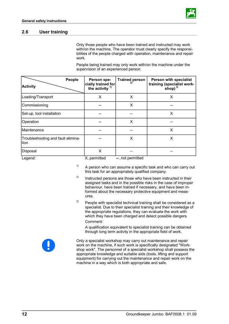
Only those people who have been trained and instructed may work with/on the machine. The operator must clearly specify the responsi-bilities of the people charged with operation, maintenance and repair work.
People being trained may only work with/on the machine under the supervision of an experienced person.
People
Activity
Person spe-cially trained for
the activity 1)
Trained person 2)
Person with specialist training (specialist work-
shop) 3)
Loading/Transport X X X
Commissioning -- X --
Set-up, tool installation -- -- X
Operation -- X --
Maintenance -- -- X
Troubleshooting and fault elimina-tion
-- X X
Disposal X -- --
Legend: X..permitted --..not permitted
1) A person who can assume a specific task and who can carry out this task for an appropriately qualified company.
2) Instructed persons are those who have been instructed in their assigned tasks and in the possible risks in the case of improper behaviour, have been trained if necessary, and have been in-formed about the necessary protective equipment and meas-ures.
3) People with specialist technical training shall be considered as a specialist. Due to their specialist training and their knowledge of the appropriate regulations, they can evaluate the work with which they have been charged and detect possible dangers.
Comment: A qualification equivalent to specialist training can be obtained
through long term activity in the appropriate field of work.
Only a specialist workshop may carry out maintenance and repair work on the machine, if such work is specifically designated "Work-shop work". The personnel of a specialist workshop shall possess the appropriate knowledge and suitable aids (tools, lifting and support equipment) for carrying out the maintenance and repair work on the machine in a way which is both appropriate and safe.
General safety instructions
Groundkeeper Jumbo BAF0008.1 01.09 13
2.7 Safety measures in normal operation
Only operate the machine if all the safety and protection equipment is fully functional.
Check the machine at least once a day for visible damage and check the function of the safety and protection equipment.
2.8 Dangers from residual energy
Note that there may be residual mechanical, hydraulic, pneumatic and electrical/electronic energy at the machine.
Use appropriate measures to inform the operating personnel. You can find detailed information in the relevant sections of this operating ma-nual.
2.9 Maintenance and repair work, fault elimination
Carry out prescribed setting, maintenance and inspection work in a timely manner.
Secure all media such as compressed air and the hydraulic system against unintentional start-up.
Carefully fix and secure larger subassemblies to lifting gear when carrying out replacement work.
Check all the screw connections for a firm seat. On completing main-tenance work, check the function of safety and protection equipment.
2.10 Constructive changes
You may make no changes, expansions or modifications to the ma-chine without the authorisation of AMAZONEN-WERKE. This is also valid when welding support parts.
Any expansion or modification work shall require the written approval of AMAZONEN-WERKE. Only use the modification and accessory parts released by AMAZONEN-WERKE so that the operating permit, for example, remains valid in accordance with national and interna-tional regulations.
Vehicles with an official type approval or with equipment connected to a vehicle with a valid type approval or approval for road transport according to the German road traffic regulations must be in the state specified by the approval.
WARNING
Risk of being crushed, cut, caught, drawn in or struck if support-ing parts break.
It is forbidden to: • Drill holes in the frame or on the chassis. • Increasing the size of existing holes on the frame or the chassis. • Welding support parts.
General safety instructions
14 Groundkeeper Jumbo BAF0008.1 01.09
2.10.1 Spare and wear parts and aids
Immediately replace any machine parts which are not in a perfect state.
Use only genuine spare and wear parts or the parts cleared by AMAZONEN-WERKE so that the operating permit retains its validity in accordance with national and international regulations. If you use wear and spare parts from third parties, there is no guarantee that they have been designed and manufactured in such a way as to meet the requirements placed on them.
AMAZONEN-WERKE accepts no liability for damage arising from the use of unapproved spare parts, wear parts or auxiliary materials.
2.11 Cleaning and disposal
Handle and dispose of any materials used carefully, in particular: • When carrying out work on lubrication systems and equipment and • When cleaning using solvents.
2.12 User workstation
The machine may be operated by only one person sitting in the driver's seat of the tractor.
2.13 Warning symbols and other signs on the machine
Always keep all the warning symbols of the machine clean and in a legi-ble state. Replace illegible warning symbols. You can obtain the warning symbols from your dealer using the order number (e.g. MD 075).
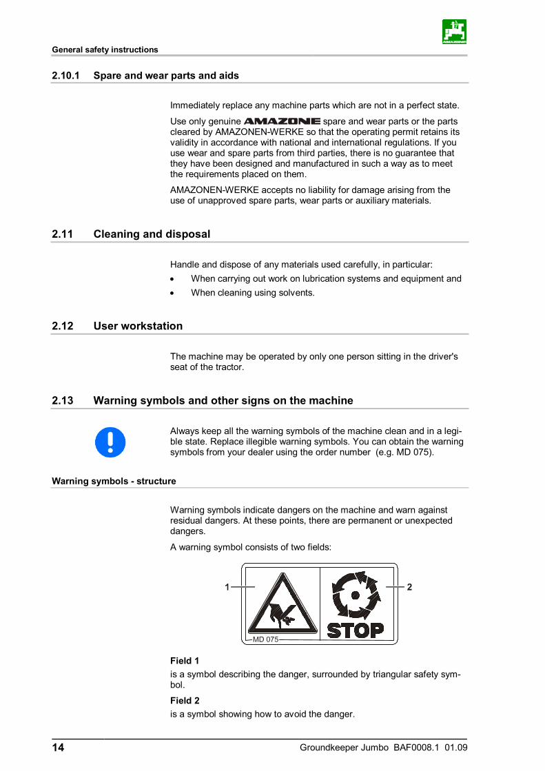
Warning symbols - structure
Warning symbols indicate dangers on the machine and warn against residual dangers. At these points, there are permanent or unexpected dangers.
A warning symbol consists of two fields:
Field 1
is a symbol describing the danger, surrounded by triangular safety sym-bol.
Field 2 is a symbol showing how to avoid the danger.
General safety instructions
Groundkeeper Jumbo BAF0008.1 01.09 15
Warning symbols - explanation
The column Order number and explanation provides an explanation of the neighbouring warning symbol. The description of the warning symbols is always the same and specifies, in the following order:
1. A description of the danger. For example: danger of cutting!
2. The consequence of nonobservance of the danger protection instructions. For example: causes serious injuries to fingers or hands.
3. Instructions for avoiding the danger. For example: only touch machine parts when they have come to a complete standstill.
General safety instructions
16 Groundkeeper Jumbo BAF0008.1 01.09
Order number and explanation Warning symbols
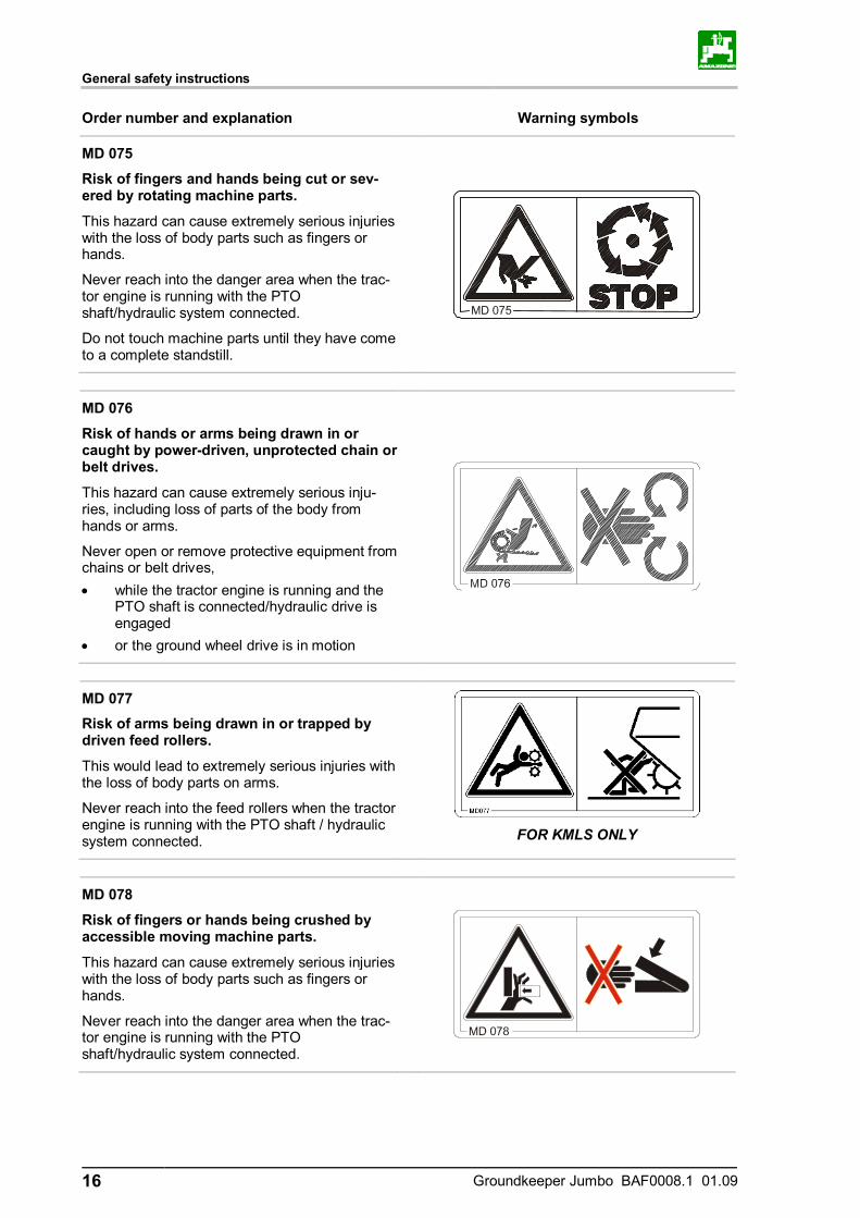
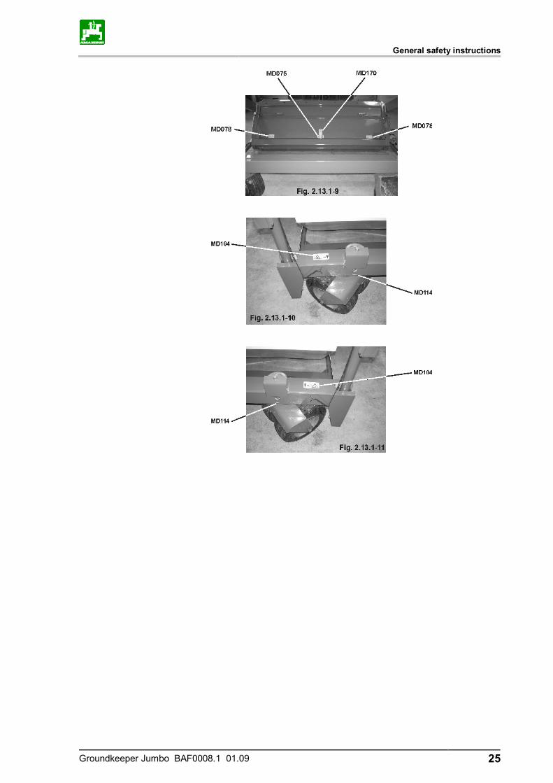
MD 075
Risk of fingers and hands being cut or sev-ered by rotating machine parts.
This hazard can cause extremely serious injuries with the loss of body parts such as fingers or hands.
Never reach into the danger area when the trac-tor engine is running with the PTO shaft/hydraulic system connected.
Do not touch machine parts until they have come to a complete standstill.
MD 076
Risk of hands or arms being drawn in or caught by power-driven, unprotected chain or belt drives.
This hazard can cause extremely serious inju-ries, including loss of parts of the body from hands or arms.
Never open or remove protective equipment from chains or belt drives, • while the tractor engine is running and the
PTO shaft is connected/hydraulic drive is engaged
• or the ground wheel drive is in motion
MD 077 Risk of arms being drawn in or trapped by driven feed rollers.
This would lead to extremely serious injuries with the loss of body parts on arms.
Never reach into the feed rollers when the tractor engine is running with the PTO shaft / hydraulic system connected.
FOR KMLS ONLY
MD 078
Risk of fingers or hands being crushed by accessible moving machine parts.
This hazard can cause extremely serious injuries with the loss of body parts such as fingers or hands.
Never reach into the danger area when the trac-tor engine is running with the PTO shaft/hydraulic system connected.
General safety instructions
Groundkeeper Jumbo BAF0008.1 01.09 17
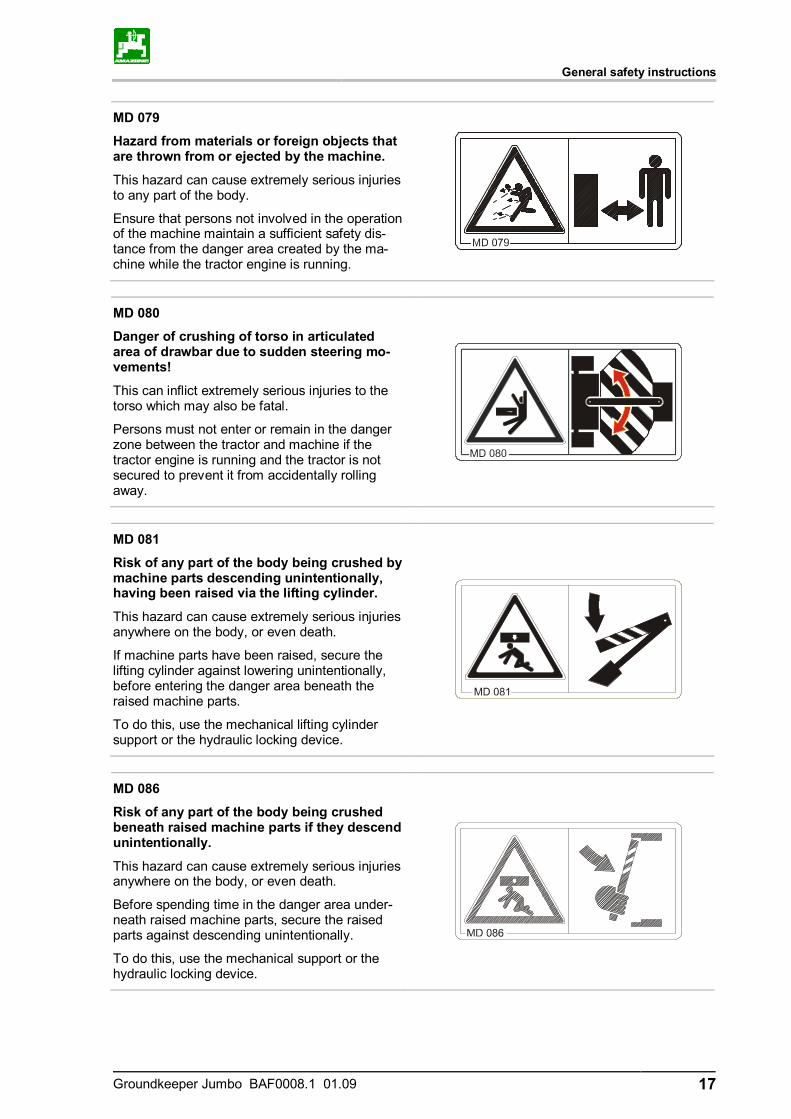
MD 079
Hazard from materials or foreign objects that are thrown from or ejected by the machine.
This hazard can cause extremely serious injuries to any part of the body.
Ensure that persons not involved in the operation of the machine maintain a sufficient safety dis-tance from the danger area created by the ma-chine while the tractor engine is running.
MD 080
Danger of crushing of torso in articulated area of drawbar due to sudden steering mo-vements!
This can inflict extremely serious injuries to the torso which may also be fatal.
Persons must not enter or remain in the danger zone between the tractor and machine if the tractor engine is running and the tractor is not secured to prevent it from accidentally rolling away.
MD 081
Risk of any part of the body being crushed by machine parts descending unintentionally, having been raised via the lifting cylinder.
This hazard can cause extremely serious injuries anywhere on the body, or even death.
If machine parts have been raised, secure the lifting cylinder against lowering unintentionally, before entering the danger area beneath the raised machine parts.
To do this, use the mechanical lifting cylinder support or the hydraulic locking device.
MD 086
Risk of any part of the body being crushed beneath raised machine parts if they descend unintentionally.
This hazard can cause extremely serious injuries anywhere on the body, or even death.
Before spending time in the danger area under-neath raised machine parts, secure the raised parts against descending unintentionally.
To do this, use the mechanical support or the hydraulic locking device.

General safety instructions
18 Groundkeeper Jumbo BAF0008.1 01.09
MD 087
Risk of toes or feet being cut or severed by power-driven tools.
This hazard can cause serious injuries, including loss of parts of the body from toes or feet.
Maintain a sufficient safety distance from the danger area while the tractor engine is running and the PTO shaft/hydraulic system is con-nected.
MD 090
Risk of contusions from unintentional rolling of the uncoupled, unsecured machine!
This hazard can cause extremely serious injuries anywhere on the body, or even death.
Secure the machine against unintentional rolling, before uncoupling the machine from the tractor. To do this, use the parking brake and/or the wheel chock(s).
MD 093
Risk of catching or entrapment for entire bo-dy due to unguarded driven drive shafts.
This hazard can cause extremely serious injuries anywhere on the body, or even death.
Never open or remove guard devices from drive shafts when the tractor engine is running with the PTO shaft connected / hydraulic drive engaged.
MD 095
Read and understand the operating manual safe-ty information before starting up the machine!

General safety instructions
Groundkeeper Jumbo BAF0008.1 01.09 19
MD 096
Danger of infection to the whole body from liquids escaping at a high pressure (hydraulic fluid)!
This danger will cause serious injuries over the whole body, if hydraulic fluid escaping at high pressure passes through the skin and into the body.
Never attempt to plug leaks in hydraulic lines using your hand or fingers.
Read and understand the information in the op-erating manual before carrying out maintenance and repair work.
If you are injured by hydraulic fluid, contact a doctor immediately.
MD 097
Risk of crushing torso in the stroke range of the three-point suspension due to narrowing spaces when the three-point hydraulic sys-tem is actuated.
This would cause extremely serious injuries and even death.
Persons must not enter the stroke area of the three-point suspension when the three-point hydraulics are actuated.
Actuate the operating controls for the tractor's three-point hydraulic system • from the designated workstation, • if you are outside the danger area between
the tractor and the machine.
MD 100
This symbol indicates lashing points for fastening slinging gear when loading the machine.
General safety instructions
20 Groundkeeper Jumbo BAF0008.1 01.09
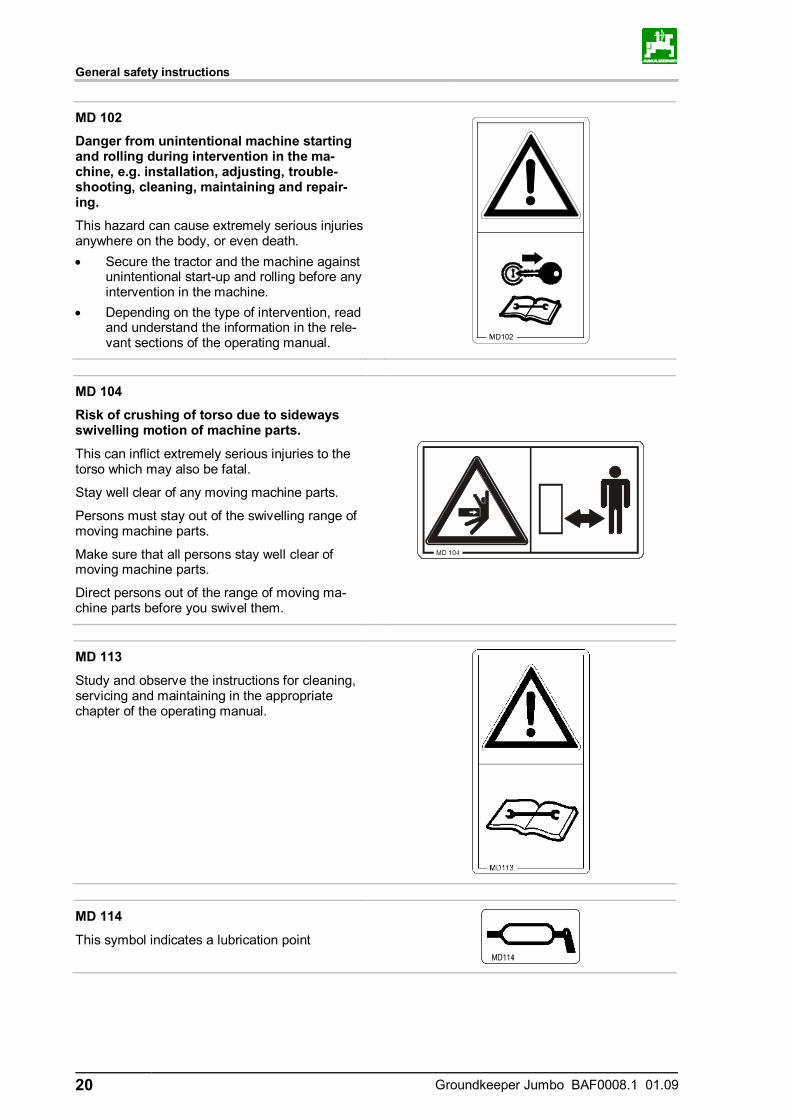
MD 102
Danger from unintentional machine starting and rolling during intervention in the ma-chine, e.g. installation, adjusting, trouble-shooting, cleaning, maintaining and repair-ing.
This hazard can cause extremely serious injuries anywhere on the body, or even death. • Secure the tractor and the machine against
unintentional start-up and rolling before any intervention in the machine.
• Depending on the type of intervention, read and understand the information in the rele-vant sections of the operating manual.
MD 104
Risk of crushing of torso due to sideways swivelling motion of machine parts.
This can inflict extremely serious injuries to the torso which may also be fatal.
Stay well clear of any moving machine parts.
Persons must stay out of the swivelling range of moving machine parts.
Make sure that all persons stay well clear of moving machine parts.
Direct persons out of the range of moving ma-chine parts before you swivel them.
MD 113
Study and observe the instructions for cleaning, servicing and maintaining in the appropriate chapter of the operating manual.
MD 114
This symbol indicates a lubrication point
General safety instructions
Groundkeeper Jumbo BAF0008.1 01.09 21
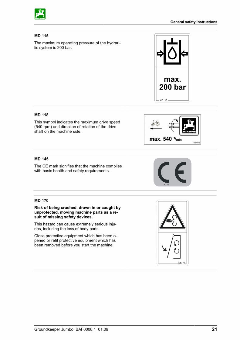
MD 115
The maximum operating pressure of the hydrau-lic system is 200 bar.
MD 118
This symbol indicates the maximum drive speed (540 rpm) and direction of rotation of the drive shaft on the machine side.
MD 145
The CE mark signifies that the machine complies with basic health and safety requirements.
MD 170
Risk of being crushed, drawn in or caught by unprotected, moving machine parts as a re-sult of missing safety devices.
This hazard can cause extremely serious inju-ries, including the loss of body parts.
Close protective equipment which has been o-pened or refit protective equipment which has been removed before you start the machine.
General safety instructions
22 Groundkeeper Jumbo BAF0008.1 01.09
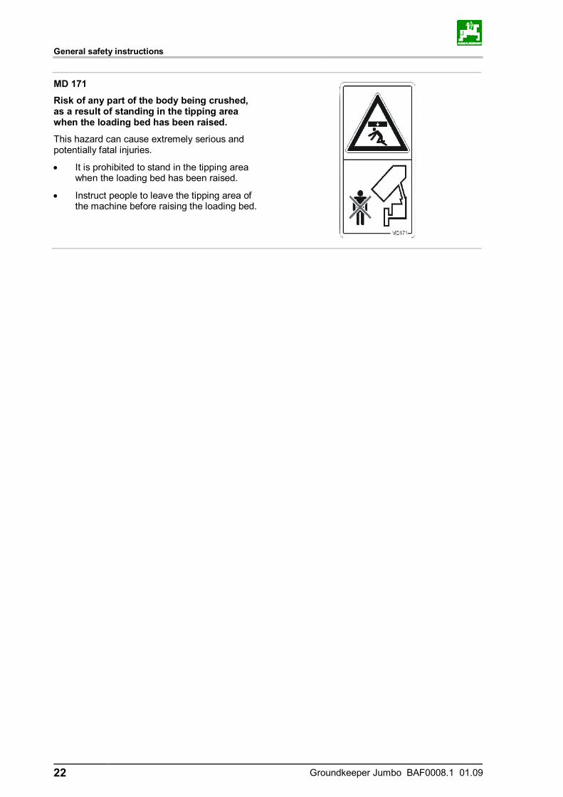
MD 171
Risk of any part of the body being crushed, as a result of standing in the tipping area when the loading bed has been raised.
This hazard can cause extremely serious and potentially fatal injuries.
• It is prohibited to stand in the tipping area when the loading bed has been raised.
• Instruct people to leave the tipping area of the machine before raising the loading bed.

General safety instructions
Groundkeeper Jumbo BAF0008.1 01.09 23
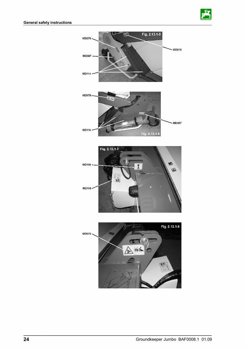
2.13.1 Positioning of warning symbols and other labels
Warning symbols
The following diagrams show the arrangement of the warning symbols on the machine.
General safety instructions
24 Groundkeeper Jumbo BAF0008.1 01.09
General safety instructions
Groundkeeper Jumbo BAF0008.1 01.09 25

General safety instructions
26 Groundkeeper Jumbo BAF0008.1 01.09
2.14 Dangers if the safety information is not observed
Non observance of the safety information • Can pose both a danger to people and also to the environment
and machine. • Can lead to the loss of all warranty claims.
Seen individually, non-compliance with the safety information could pose the following risks: • Danger to people through non-secured working areas. • Failure of important machine functions. • Failure of prescribed methods of maintenance and repair. • Danger to people through mechanical and chemical impacts. • Risk to environment through leakage of hydraulic fluid.
2.15 Safety-conscious working
Besides the safety information in this operating manual, the national general workplace safety and accident prevention regulations are binding.
Comply with the accident prevention instructions on the warning sym-bols.
When driving on public roads and routes, comply with the appropriate statutory road traffic regulations.
General safety instructions
Groundkeeper Jumbo BAF0008.1 01.09 27
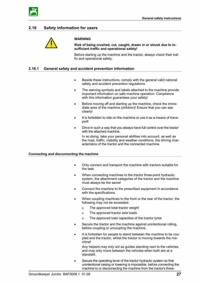
2.16 Safety information for users
WARNING
Risk of being crushed, cut, caught, drawn in or struck due to in-sufficient traffic and operational safety!
Before starting up the machine and the tractor, always check their traf-fic and operational safety.
2.16.1 General safety and accident prevention information
• Beside these instructions, comply with the general valid national
safety and accident prevention regulations.
• The warning symbols and labels attached to the machine provide important information on safe machine operation. Compliance with this information guarantees your safety!
• Before moving off and starting up the machine, check the imme-diate area of the machine (children)! Ensure that you can see clearly!
• It is forbidden to ride on the machine or use it as a means of trans-port!
• Drive in such a way that you always have full control over the tractor with the attached machine.
In so doing, take your personal abilities into account, as well as the road, traffic, visibility and weather conditions, the driving char-acteristics of the tractor and the connected machine.
Connecting and disconnecting the machine
• Only connect and transport the machine with tractors suitable for
the task.
• When connecting machines to the tractor three-point hydraulic system, the attachment categories of the tractor and the machine must always be the same!
• Connect the machine to the prescribed equipment in accordance with the specifications.
• When coupling machines to the front or the rear of the tractor, the following may not be exceeded: ο The approved total tractor weight ο The approved tractor axle loads ο The approved load capacities of the tractor tyres
• Secure the tractor and the machine against unintentional rolling, before coupling or uncoupling the machine.
• It is forbidden for people to stand between the machine to be cou-pled and the tractor, whilst the tractor is moving towards the ma-chine!
Any helpers may only act as guides standing next to the vehicles, and may only move between the vehicles when both are at a standstill.
• Secure the operating lever of the tractor hydraulic system so that unintentional raising or lowering is impossible, before connecting the machine to or disconnecting the machine from the tractor's three-
General safety instructions
28 Groundkeeper Jumbo BAF0008.1 01.09
point hydraulic system.
• When coupling and uncoupling machines, move the support equipment (if available) to the appropriate position (stability).
• When actuating the support equipment, there is a risk of injury from nip and shear points.
• Be particularly careful when coupling the machine to the tractor or uncoupling it from the tractor! There are nip and shear points in the area of the coupling point between the tractor and the ma-chine.
• It is forbidden to stand between the tractor and the machine when actuating the three-point hydraulic system.
• Coupled supply lines: ο Must give without tension, bending or rubbing on all move-
ments when travelling round corners. ο May not scour other parts.
• The release ropes for quick action couplings must hang loosely and may not release themselves when lowered.
• Also ensure that uncoupled machines are stable!
Use of the machine
• Before starting work, ensure that you understand all the equip-
ment and actuation elements of the machine and their function. There is no time for this when the machine is already in opera-tion!
• Do not wear loose-fitting clothing! Loose clothing increases the risk over being caught by drive shafts!
• Only start-up the machine, when all the safety equipment has been attached and is in the safety position!
• Comply with the maximum load of the connected machine and the approved axle and support loads of the tractor. If necessary, drive only with a partially-filled catcher.
• It is forbidden to stand in the working area of the machine.
• It is forbidden to stand in the turning and rotation area of the machine.
• There are contusion and cutting points at externally-actuated (e.g. hydraulic) machine points.
• Only actuate externally-actuated machine parts when you are sure that there is no-one within a sufficient distance from the machine!
• Secure the tractor against unintentional start-up and rolling be-fore you leave the tractor.
For this: ο Lower the machine onto the ground ο Apply the parking brake ο Switch off the tractor engine ο Remove the ignition key
General safety instructions
Groundkeeper Jumbo BAF0008.1 01.09 29
Machine transportation
• When using public highways, national road traffic regulations
must be observed.
• Before moving off, check: ο the correct connection of the supply lines ο the lighting system for damage, function and cleanliness ο the brake and hydraulic system for visible damage ο that the parking brake is released completely ο the proper functioning of the braking system
• Ensure that the tractor has sufficient steering and braking power. Any machines and front/rear weights connected to the tractor in-fluence the driving behaviour and the steering and braking power of the tractor.
• If necessary, use front weights. The front tractor axle must always be loaded with at least 20 %
of the empty tractor weight, in order to ensure sufficient steering power.
• Always fix the front or rear weights to the intended fixing points according to regulations.
• Comply with the maximum load of the connected machine and the approved axle and support loads of the tractor.
• The tractor must guarantee the prescribed brake delay for the loaded vehicle combination (tractor plus connected machine).
• Check the brake power before moving off.
• When turning corners with the machine connected, take the broad load and balance weight of the machine into account.
• Before moving off, ensure sufficient side locking of the tractor lower links, when the machine is fixed to the three-point hydrau-lic system or lower links of the tractor.
• Before moving off, move all the swivel machine parts to the transport position.
• Before moving off, secure all the swivel machine parts in the transport position against risky position changes. Use the trans-port locks intended for this.
• Before moving off, secure the operating lever of the three-point hydraulic system against unintentional raising or lowering of the connected machine.
• Check that the transport equipment, e.g. lighting, warning e-quipment and protective equipment, is correctly mounted on the machine.
• Before transportation, carry out a visual check that the upper and lower link pins are firmly fixed with the lynch pin against uninten-tional release.
• Adjust your driving speed to the prevailing conditions.
• Before driving downhill, switch to a low gear.
• Before moving off, always switch off the independent wheel braking (lock the pedals).
General safety instructions
30 Groundkeeper Jumbo BAF0008.1 01.09
2.16.2 Hydraulic system
• The hydraulic system is under a high pressure.
• Ensure that the hydraulic hose lines are connected correctly.
• When connecting the hydraulic hose lines, ensure that the hy-draulic system is unpressurised on both the machine and tractor sides.
• It is forbidden to block the operator controls on the tractor which are used for hydraulic and electrical movements of components, e.g. folding, swivelling and pushing movements. The movement must stop automatically when you release the appropriate con-trol. This does not apply to equipment movements that: ο are continuous or ο are automatically locked or ο necessarily require an open centre or pressure position to
operate correctly
• Before working on the hydraulic system ο Lower the machine ο Depressurise the hydraulic system ο Switch off the tractor engine ο Apply the parking brake ο Remove the ignition key
• Have the hydraulic hose line checked at least once a year by a specialist for proper functioning.
• Replace the hydraulic hose line if it is damaged or worn. Only use original hydraulic hose lines.
• The hydraulic hose lines should not be used for longer than six years, including any storage time of maximum two years. Even with proper storage and approved use, hoses and hose connec-tions are subject to natural ageing, thus limiting the length of use. However, it may be possible to specify the length of use from experience values, in particular when taking the risk poten-tial into account. In the case of hoses and hose connections ma-de from thermoplastics, other guide values may be decisive.
• Never attempt to plug leaks in hydraulic lines using your hand or fingers.
Escaping high pressure fluid (hydraulic fluid) may pass through the skin and ingress into the body, causing serious injuries! If you are injured by hydraulic fluid, contact a doctor immediately. Danger of infection.
• When searching for leakage points, use suitable aids, to avoid the serious risk of infection.
General safety instructions
Groundkeeper Jumbo BAF0008.1 01.09 31
2.16.3 Electrical system
• When working on the electrical system, always disconnect the battery (negative terminal).
• Only use the prescribed fuses. If fuses are used with too high a rating, the electrical system will be destroyed – danger of fire.
• Ensure that the battery is connected correctly - firstly connect the positive terminal and then connect the negative terminal. When disconnecting the battery, disconnect the negative terminal first, followed by the positive terminal.
• Always place the appropriate cover over the positive battery termi-nal. Contact with earth may cause an explosion
• Risk of explosion: avoid the production of sparks or the presence of naked flames in the vicinity of the battery.
• The machine can be equipped with electronic components and units, whose function may be influenced by electromagnetic in-terference from other devices. Such influences can lead to per-sonal hazard if the following safety information is not followed. ο If electrical units and/or components are retrofitted on the
machine, which require a connection to the on-board power supply, the user must assume responsibility for checking whether the retrofit causes faults in the vehicle electronics or in other components.
ο Ensure that the retrofitted electrical and electronic compo-nents comply with the EMC directive 89/336/EEC in the ap-propriate version and carry the CE mark.
General description of the machine
32 Groundkeeper Jumbo BAF0008.1 01.09
3 General description of the machine
3.1 Areas of application
The AMAZONE Groundkeeper Jumbo GHS is designed for mowing and scarifying grassed areas in public parks, sports fields and gar-dens, etc. It can be used to collect and chop foliage in the autumn.
3.2 Declaration of conformity
The Groundkeeper Jumbo complies with the requirements of EC Ma-chinery Directive 89/392/EC and corresponding supplementary guide-lines.
3.3 Details required for enquiries
When ordering special optional equipment and spare parts, please always quote the machine number of your Groundkeeper Jumbo. Safety requirements are only fulfilled if genuine AMAZONE spare parts are used when a repair is undertaken. The use of other parts may remove liability for any consequences which may oc-cur as a result.
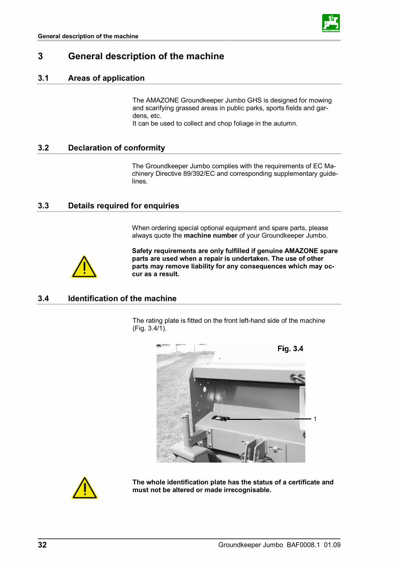
3.4 Identification of the machine
The rating plate is fitted on the front left-hand side of the machine (Fig. 3.4/1).
The whole identification plate has the status of a certificate and must not be altered or made irrecognisable.
General description of the machine
Groundkeeper Jumbo BAF0008.1 01.09 33
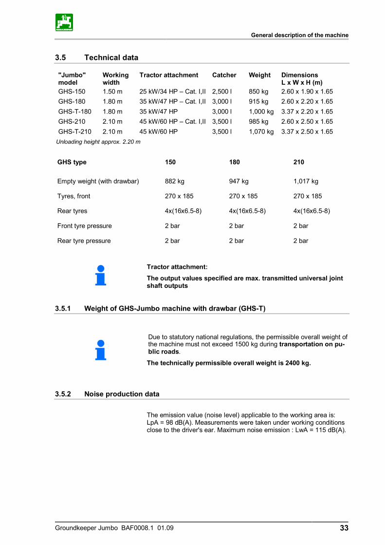
3.5 Technical data
"Jumbo" model
Working width
Tractor attachment Catcher Weight Dimensions L x W x H (m)
GHS-150 1.50 m 25 kW/34 HP – Cat. I,II 2,500 l 850 kg 2.60 x 1.90 x 1.65 GHS-180 1.80 m 35 kW/47 HP – Cat. I,II 3,000 l 915 kg 2.60 x 2.20 x 1.65 GHS-T-180 1.80 m 35 kW/47 HP 3,000 l 1,000 kg 3.37 x 2.20 x 1.65 GHS-210 2.10 m 45 kW/60 HP – Cat. I,II 3,500 l 985 kg 2.60 x 2.50 x 1.65 GHS-T-210 2.10 m 45 kW/60 HP 3,500 l 1,070 kg 3.37 x 2.50 x 1.65
Unloading height approx. 2.20 m
GHS type 150 180 210
Empty weight (with drawbar) 882 kg 947 kg 1,017 kg Tyres, front 270 x 185 270 x 185 270 x 185 Rear tyres 4x(16x6.5-8) 4x(16x6.5-8) 4x(16x6.5-8) Front tyre pressure 2 bar 2 bar 2 bar Rear tyre pressure 2 bar 2 bar 2 bar
Tractor attachment:
The output values specified are max. transmitted universal joint shaft outputs
3.5.1 Weight of GHS-Jumbo machine with drawbar (GHS-T)
Due to statutory national regulations, the permissible overall weight of the machine must not exceed 1500 kg during transportation on pu-blic roads.
The technically permissible overall weight is 2400 kg.
3.5.2 Noise production data
The emission value (noise level) applicable to the working area is: LpA = 98 dB(A). Measurements were taken under working conditions close to the driver's ear. Maximum noise emission : LwA = 115 dB(A).
General description of the machine
34 Groundkeeper Jumbo BAF0008.1 01.09
3.6 Intended use
This Amazone Groundkeeper Jumbo has been designed exclusively for conventional use in the upkeep of grassed open areas and parks (intended use). Any use which goes beyond these limits is not regarded as the in-tended use. The manufacturer is not liable for any damages which may result from such use. The risk involved in such use is borne solely by the user. Intended use also includes compliance with instructions specified by the manufacturer concerning operation, servicing and maintenance as well as the exclusive use of genuine AMAZONE spare parts. This Amazone Groundkeeper Jumbo may only be used, serviced and maintained by persons who are familiar with the machine and have received instruction concerning the risks involved. All relevant accident prevention regulations and any other generally recognised rules relevant to safety, occupational health and traffic laws must be observed and the safety instructions on the labels at-tached to the machine must be strictly followed. Any unauthorised modification of the machine will automatically render all warranty claims against the manufacturer for resulting damage invalid.
Taking delivery of the machine
Groundkeeper Jumbo BAF0008.1 01.09 35
4 Taking delivery of the machine
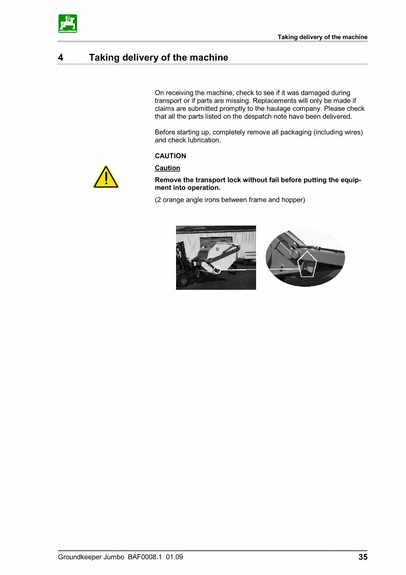
On receiving the machine, check to see if it was damaged during transport or if parts are missing. Replacements will only be made if claims are submitted promptly to the haulage company. Please check that all the parts listed on the despatch note have been delivered.
Before starting up, completely remove all packaging (including wires) and check lubrication.
CAUTION
Caution
Remove the transport lock without fail before putting the equip-ment into operation.
(2 orange angle irons between frame and hopper)
Attaching and removing the machine at the tractor's rear three-point system
36 Groundkeeper Jumbo BAF0008.1 01.09
5 Attaching and removing the machine at the tractor's rear three-point system
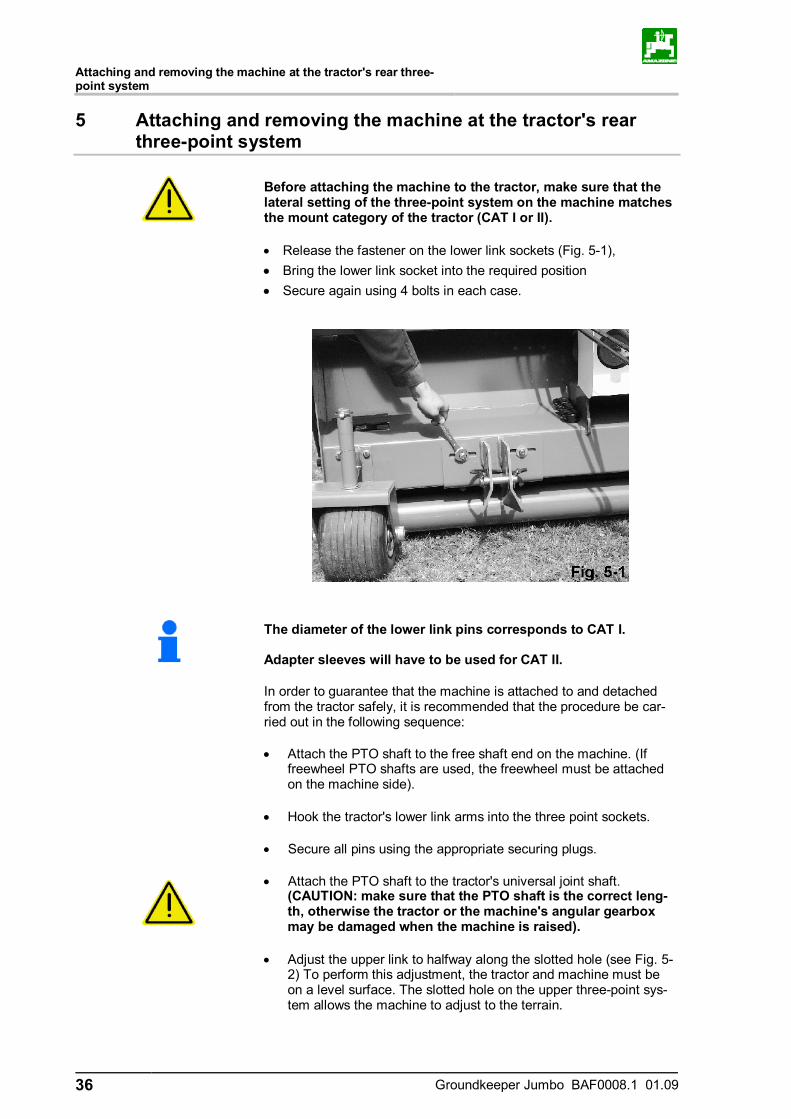
Before attaching the machine to the tractor, make sure that the lateral setting of the three-point system on the machine matches the mount category of the tractor (CAT I or II).
• Release the fastener on the lower link sockets (Fig. 5-1), • Bring the lower link socket into the required position • Secure again using 4 bolts in each case.
The diameter of the lower link pins corresponds to CAT I. Adapter sleeves will have to be used for CAT II.
In order to guarantee that the machine is attached to and detached from the tractor safely, it is recommended that the procedure be car-ried out in the following sequence: • Attach the PTO shaft to the free shaft end on the machine. (If
freewheel PTO shafts are used, the freewheel must be attached on the machine side).
• Hook the tractor's lower link arms into the three point sockets.
• Secure all pins using the appropriate securing plugs.
• Attach the PTO shaft to the tractor's universal joint shaft. (CAUTION: make sure that the PTO shaft is the correct leng-th, otherwise the tractor or the machine's angular gearbox may be damaged when the machine is raised).
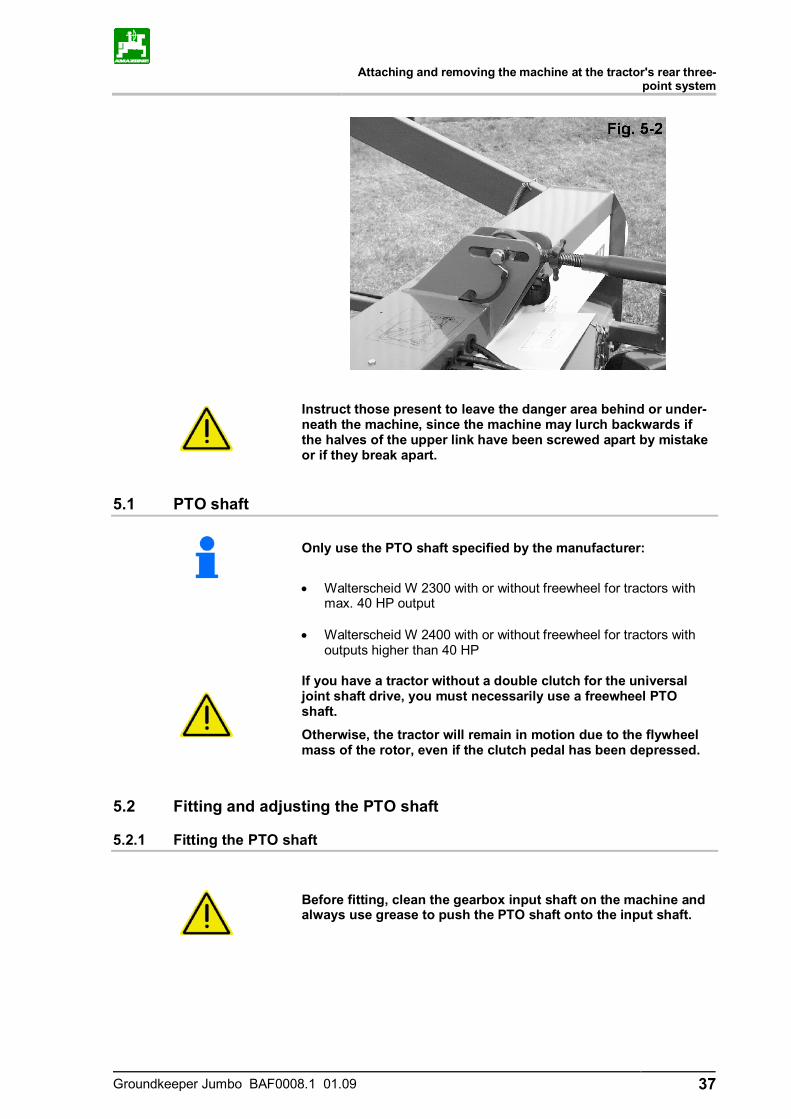
• Adjust the upper link to halfway along the slotted hole (see Fig. 5-2) To perform this adjustment, the tractor and machine must be on a level surface. The slotted hole on the upper three-point sys-tem allows the machine to adjust to the terrain.
Attaching and removing the machine at the tractor's rear three-
point system
Groundkeeper Jumbo BAF0008.1 01.09 37
Instruct those present to leave the danger area behind or under-neath the machine, since the machine may lurch backwards if the halves of the upper link have been screwed apart by mistake or if they break apart.
5.1 PTO shaft
Only use the PTO shaft specified by the manufacturer:
• Walterscheid W 2300 with or without freewheel for tractors with max. 40 HP output
• Walterscheid W 2400 with or without freewheel for tractors with
outputs higher than 40 HP
If you have a tractor without a double clutch for the universal joint shaft drive, you must necessarily use a freewheel PTO shaft.
Otherwise, the tractor will remain in motion due to the flywheel mass of the rotor, even if the clutch pedal has been depressed.
5.2 Fitting and adjusting the PTO shaft
5.2.1 Fitting the PTO shaft
Before fitting, clean the gearbox input shaft on the machine and always use grease to push the PTO shaft onto the input shaft.
Attaching and removing the machine at the tractor's rear three-point system
38 Groundkeeper Jumbo BAF0008.1 01.09
5.2.2 Adjusting the PTO shaft when first attached
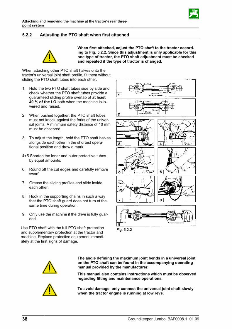
When first attached, adjust the PTO shaft to the tractor accord-ing to Fig. 5.2.2. Since this adjustment is only applicable for this one type of tractor, the PTO shaft adjustment must be checked and repeated if the type of tractor is changed.
When attaching other PTO shaft halves onto the tractor's universal joint shaft profile, fit them without sliding the PTO shaft tubes into each other. 1. Hold the two PTO shaft tubes side by side and
check whether the PTO shaft tubes provide a guaranteed sliding profile overlap of at least 40 % of the LO both when the machine is lo-wered and raised.
2. When pushed together, the PTO shaft tubes
must not knock against the forks of the univer-sal joints. A minimum safety distance of 10 mm must be observed.
3. To adjust the length, hold the PTO shaft halves
alongside each other in the shortest opera-tional position and draw a mark.
4+5.Shorten the inner and outer protective tubes
by equal amounts. 6. Round off the cut edges and carefully remove
swarf. 7. Grease the sliding profiles and slide inside
each other. 8. Hook in the supporting chains in such a way
that the PTO shaft guard does not turn at the same time during operation.
9. Only use the machine if the drive is fully guar-
ded.
Use PTO shaft with the full PTO shaft protection and supplementary protection at the tractor and machine. Replace protective equipment immedi-ately at the first signs of damage.
The angle defining the maximum joint bends in a universal joint on the PTO shaft can be found in the accompanying operating manual provided by the manufacturer.
This manual also contains instructions which must be observed regarding fitting and maintenance operations.
To avoid damage, only connect the universal joint shaft slowly when the tractor engine is running at low revs.
Attaching and removing the machine at the tractor's rear three-
point system
Groundkeeper Jumbo BAF0008.1 01.09 39
5.3 Groundkeeper Jumbo gearbox input speed
The gearbox on the Groundkeeper Jumbo has a universal joint shaft connection. The machine must be powered with a maximum drive speed of 540 rpm:
Drive speed n = 540 rpm.
Higher drive speeds than specified will cause the rotor to turn at significantly higher speeds. In extreme cases, this may lead to blades being released which could create a hazard for operating personnel.
Warranty claims for damage which can be traced back to an ex-cessively high drive speed of the universal joint shaft will not be recognised.
5.4 Connecting the hydraulics
In order to be able to work correctly with the machine, the following hydraulic joint must be fitted on the tractor side.
5.4.1 Electrically controlled hydraulic block (optional, country-specific)
The remote control supplied with the machine is held in place in the driver's cab by the holder provided and allows the machine to be op-erated using only two hydraulic lines and one additional electrical connection.
Connection 1: permanent pressure connection
required hydraulic power: 200 bar
40 l/min
Connection 2: free return
max. return pressure: 1.5 bar
Connection 3: electrical socket, 3-pin
required electrical power: 12 V
15 A

Attaching and removing the machine at the tractor's rear three-point system
40 Groundkeeper Jumbo BAF0008.1 01.09
If the tractor has no connection for the electrical system, an optional additional cable with socket can be obtained from .
CAUTION If you connect this cable incorrectly to the battery the hydroelec-tric control system may be severely damaged. Connect the cable as follows:
(-) Earth = blue
(+) Voltage = brown
Explanation of the remote control (Fig. 5.4.1-2):
1- On/Off switch
2- Raise and lower the drawbar
3- Raise and lower the hopper (only with GHS-T)
4- Extend and retract the rear hydraulic cylinders
4+5- Machine in float position when both switches are operated simultaneously
Attaching and removing the machine at the tractor's rear three-
point system
Groundkeeper Jumbo BAF0008.1 01.09 41
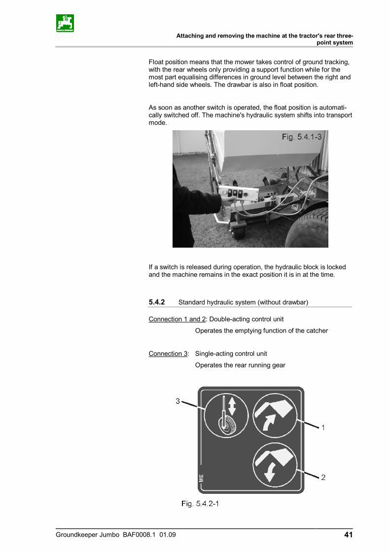
Float position means that the mower takes control of ground tracking, with the rear wheels only providing a support function while for the most part equalising differences in ground level between the right and left-hand side wheels. The drawbar is also in float position.
As soon as another switch is operated, the float position is automati-cally switched off. The machine's hydraulic system shifts into transport mode.
If a switch is released during operation, the hydraulic block is locked and the machine remains in the exact position it is in at the time.
5.4.2 Standard hydraulic system (without drawbar)
Connection 1 and 2: Double-acting control unit
Operates the emptying function of the catcher
Connection 3: Single-acting control unit
Operates the rear running gear
Attaching and removing the machine at the tractor's rear three-point system
42 Groundkeeper Jumbo BAF0008.1 01.09
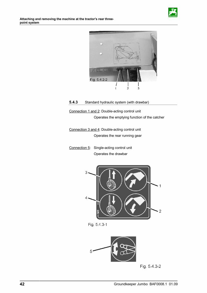
5.4.3 Standard hydraulic system (with drawbar)
Connection 1 and 2: Double-acting control unit
Operates the emptying function of the catcher
Connection 3 and 4: Double-acting control unit
Operates the rear running gear
Connection 5: Single-acting control unit
Operates the drawbar
Attaching and removing the machine at the tractor's rear three-
point system
Groundkeeper Jumbo BAF0008.1 01.09 43
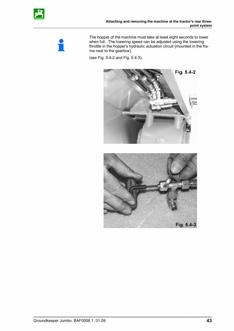
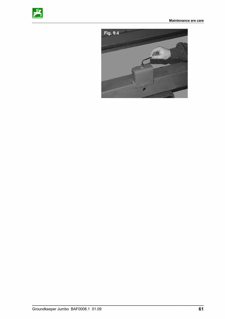
The hopper of the machine must take at least eight seconds to lower when full. The lowering speed can be adjusted using the lowering throttle in the hopper's hydraulic actuation circuit (mounted in the fra-me next to the gearbox).
(see Fig. 5.4-2 and Fig. 5.4-3).
The mower unit
44 Groundkeeper Jumbo BAF0008.1 01.09
6 The mower unit
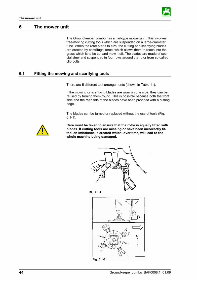
The Groundkeeper Jumbo has a flail-type mower unit. This involves free-moving cutting tools which are suspended on a large-diameter tube. When the rotor starts to turn, the cutting and scarifying blades are erected by centrifugal force, which allows them to reach into the grass which is to be cut and mow it off. The blades are made of spe-cial steel and suspended in four rows around the rotor from so-called clip bolts
6.1 Fitting the mowing and scarifying tools
There are 5 different tool arrangements (shown in Table 11). If the mowing or scarifying blades are worn on one side, they can be reused by turning them round. This is possible because both the front side and the rear side of the blades have been provided with a cutting edge.
The blades can be turned or replaced without the use of tools (Fig. 6.1-1).
Care must be taken to ensure that the rotor is equally fitted with blades. If cutting tools are missing or have been incorrectly fit-ted, an imbalance is created which, over time, will lead to the whole machine being damaged.
The mower unit
Groundkeeper Jumbo BAF0008.1 01.09 45
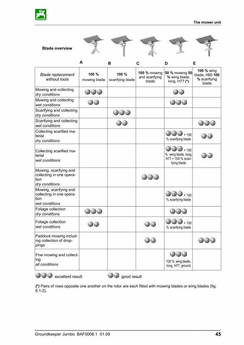
Blade overview
A
B
C
D
E
Blade replacement without tools
100 % mowing blade
100 % scarifying blade
100 % mowing and scarifying
blade
50 % mowing 50 % wing blade, long, H77 (*)
100 % wing blade, H60 100
% scarifying blade
Mowing and collecting dry conditions
Mowing and collecting wet conditions
Scarifying and collecting dry conditions
Scarifying and collecting wet conditions Collecting scarified ma-terial dry conditions
+ 100 % scarifying blade
Collecting scarified ma-terial wet conditions
+ 100
% wing blade, long, H77 + 100 % scari-
fying blade
Mowing, scarifying and collecting in one opera-tion dry conditions
Mowing, scarifying and collecting in one opera-tion wet conditions
+ 100 % scarifying blade
Foliage collection dry conditions
Foliage collection wet conditions + 100
% scarifying blade
Paddock mowing includ-ing collection of drop-pings
Fine mowing and collect-ing all conditions
100 % wing blade, long, H77, ground
excellent result good result
(*) Pairs of rows opposite one another on the rotor are each fitted with mowing blades or wing blades (fig. 6.1-2).
The mower unit
46 Groundkeeper Jumbo BAF0008.1 01.09
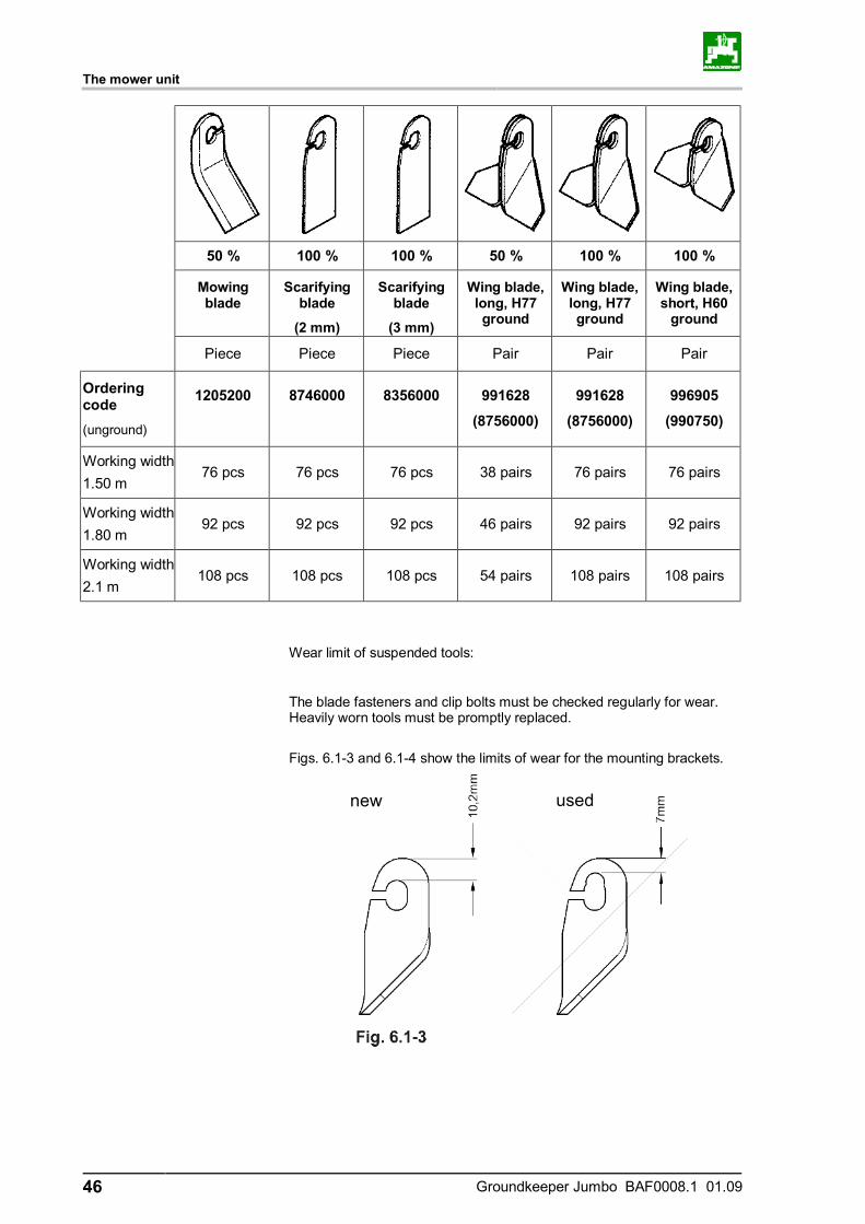
50 % 100 % 100 % 50 % 100 % 100 %
Mowing blade
Scarifying blade
(2 mm)
Scarifying blade
(3 mm)
Wing blade, long, H77 ground
Wing blade, long, H77 ground
Wing blade, short, H60
ground
Piece Piece Piece Pair Pair Pair
Ordering code (unground)
1205200
8746000
8356000
991628
(8756000)
991628
(8756000)
996905
(990750)
Working width 1.50 m
76 pcs 76 pcs 76 pcs 38 pairs 76 pairs 76 pairs
Working width 1.80 m
92 pcs 92 pcs 92 pcs 46 pairs 92 pairs 92 pairs
Working width 2.1 m
108 pcs 108 pcs 108 pcs 54 pairs 108 pairs 108 pairs
Wear limit of suspended tools:
The blade fasteners and clip bolts must be checked regularly for wear. Heavily worn tools must be promptly replaced.
Figs. 6.1-3 and 6.1-4 show the limits of wear for the mounting brackets.
used new

The mower unit
Groundkeeper Jumbo BAF0008.1 01.09 47
CAUTION
The blades and the blade fasteners must be checked before the start of every run.
All screw unions must be firmly tightened.
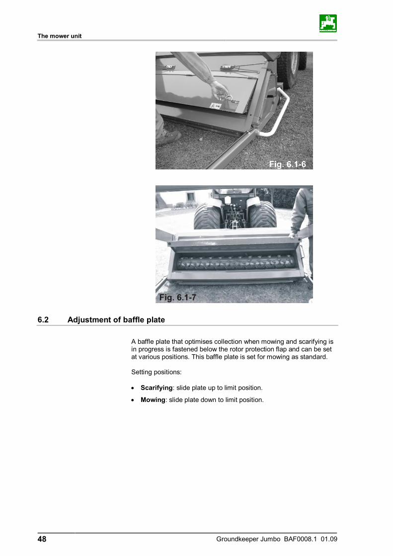
The rotor is accessed in the following manner: • Attach the machine to a tractor. • Fully raise the catcher. • Fit the safety support on the upper right-hand lifting cylinder of
the catcher (Fig. 6.1-5). • Turn off the tractor engine, • Unlock the intermediate hood (Fig. 6.1-6), • Fold up the intermediate hood (Fig. 6.1-7).
Caution:
When you intend to work on the rotor with the catcher raised, make sure that the rotor is stationary and engage the retaining hook on the container.
used new
The mower unit
48 Groundkeeper Jumbo BAF0008.1 01.09
6.2 Adjustment of baffle plate
A baffle plate that optimises collection when mowing and scarifying is in progress is fastened below the rotor protection flap and can be set at various positions. This baffle plate is set for mowing as standard. Setting positions: • Scarifying: slide plate up to limit position.
• Mowing: slide plate down to limit position.
The mower unit
Groundkeeper Jumbo BAF0008.1 01.09 49
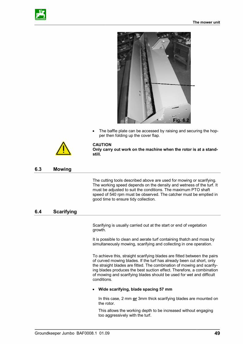
• The baffle plate can be accessed by raising and securing the hop-per then folding up the cover flap.
CAUTION Only carry out work on the machine when the rotor is at a stand-still.
6.3 Mowing
The cutting tools described above are used for mowing or scarifying. The working speed depends on the density and wetness of the turf. It must be adjusted to suit the conditions. The maximum PTO shaft speed of 540 rpm must be observed. The catcher must be emptied in good time to ensure tidy collection.
6.4 Scarifying
Scarifying is usually carried out at the start or end of vegetation growth. It is possible to clean and aerate turf containing thatch and moss by simultaneously mowing, scarifying and collecting in one operation.
To achieve this, straight scarifying blades are fitted between the pairs of curved mowing blades. If the turf has already been cut short, only the straight blades are fitted. The combination of mowing and scarify-ing blades produces the best suction effect. Therefore, a combination of mowing and scarifying blades should be used for wet and difficult conditions.
• Wide scarifying, blade spacing 57 mm
In this case, 2 mm or 3mm thick scarifying blades are mounted on the rotor.
This allows the working depth to be increased without engaging too aggressively with the turf.
The mower unit
50 Groundkeeper Jumbo BAF0008.1 01.09
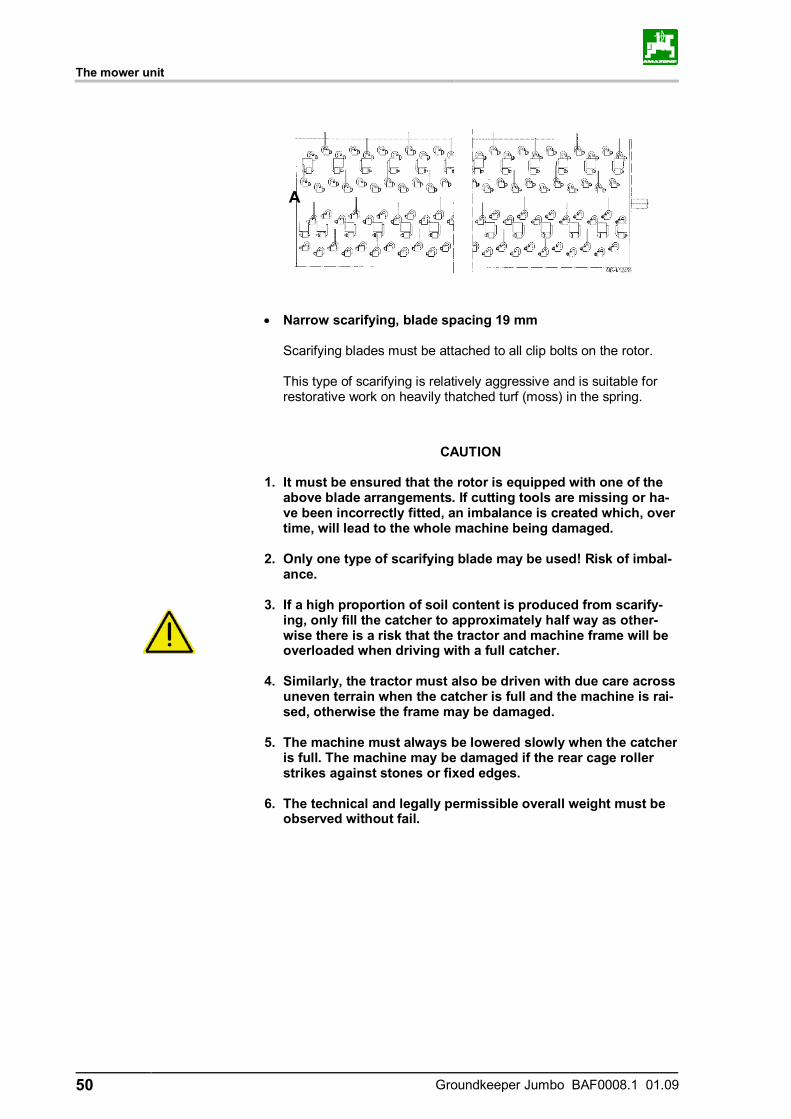
• Narrow scarifying, blade spacing 19 mm
Scarifying blades must be attached to all clip bolts on the rotor. This type of scarifying is relatively aggressive and is suitable for restorative work on heavily thatched turf (moss) in the spring.
CAUTION
1. It must be ensured that the rotor is equipped with one of the above blade arrangements. If cutting tools are missing or ha-ve been incorrectly fitted, an imbalance is created which, over time, will lead to the whole machine being damaged.
2. Only one type of scarifying blade may be used! Risk of imbal-
ance. 3. If a high proportion of soil content is produced from scarify-
ing, only fill the catcher to approximately half way as other-wise there is a risk that the tractor and machine frame will be overloaded when driving with a full catcher.
4. Similarly, the tractor must also be driven with due care across
uneven terrain when the catcher is full and the machine is rai-sed, otherwise the frame may be damaged.
5. The machine must always be lowered slowly when the catcher
is full. The machine may be damaged if the rear cage roller strikes against stones or fixed edges.
6. The technical and legally permissible overall weight must be
observed without fail.
A
The mower unit
Groundkeeper Jumbo BAF0008.1 01.09 51
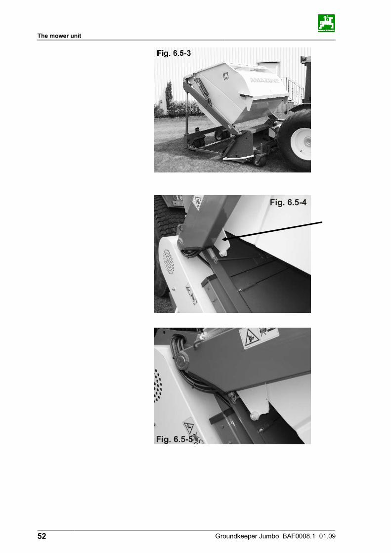
6.5 Mulching
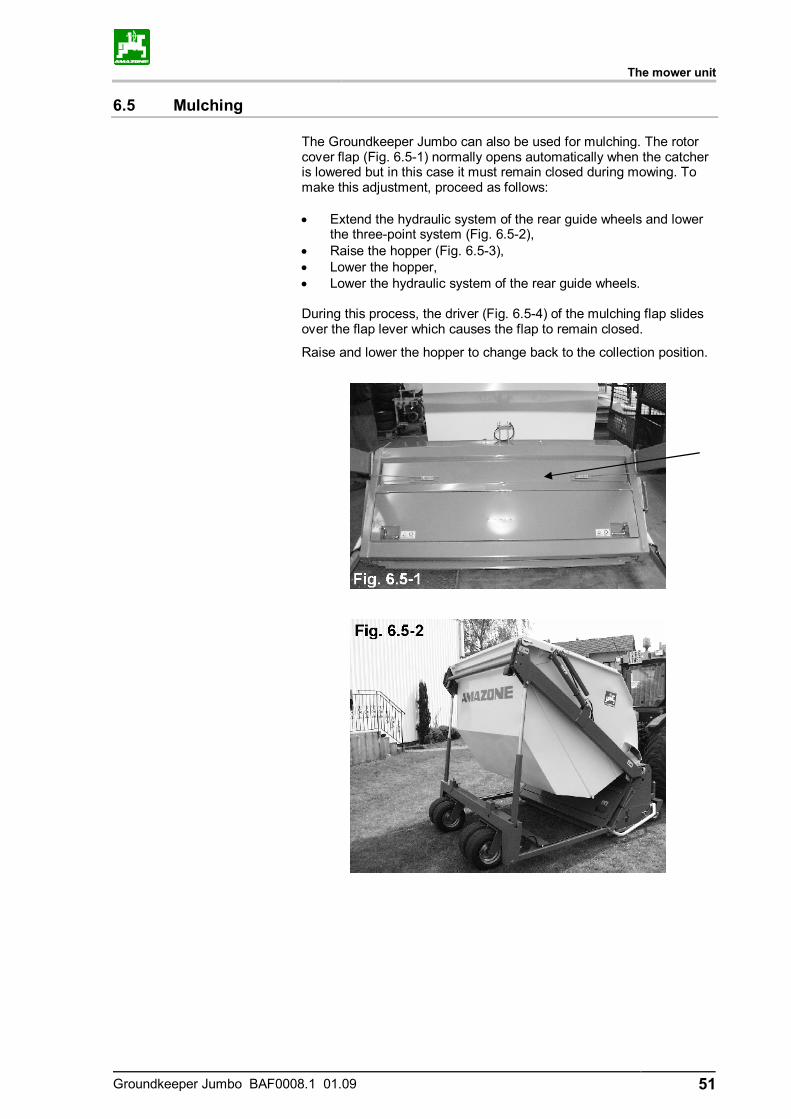
The Groundkeeper Jumbo can also be used for mulching. The rotor cover flap (Fig. 6.5-1) normally opens automatically when the catcher is lowered but in this case it must remain closed during mowing. To make this adjustment, proceed as follows: • Extend the hydraulic system of the rear guide wheels and lower
the three-point system (Fig. 6.5-2), • Raise the hopper (Fig. 6.5-3), • Lower the hopper, • Lower the hydraulic system of the rear guide wheels. During this process, the driver (Fig. 6.5-4) of the mulching flap slides over the flap lever which causes the flap to remain closed.
Raise and lower the hopper to change back to the collection position.
The mower unit
52 Groundkeeper Jumbo BAF0008.1 01.09
The mower unit
Groundkeeper Jumbo BAF0008.1 01.09 53
6.6 Collecting
Because of the strong suction effect produced by the rotor, the ma-chine can also be used for collecting material which has already been mowed or any other material lying loose on the ground. The speed of the universal joint shaft and the forward speed must be adapted to the weather conditions and material being collected.
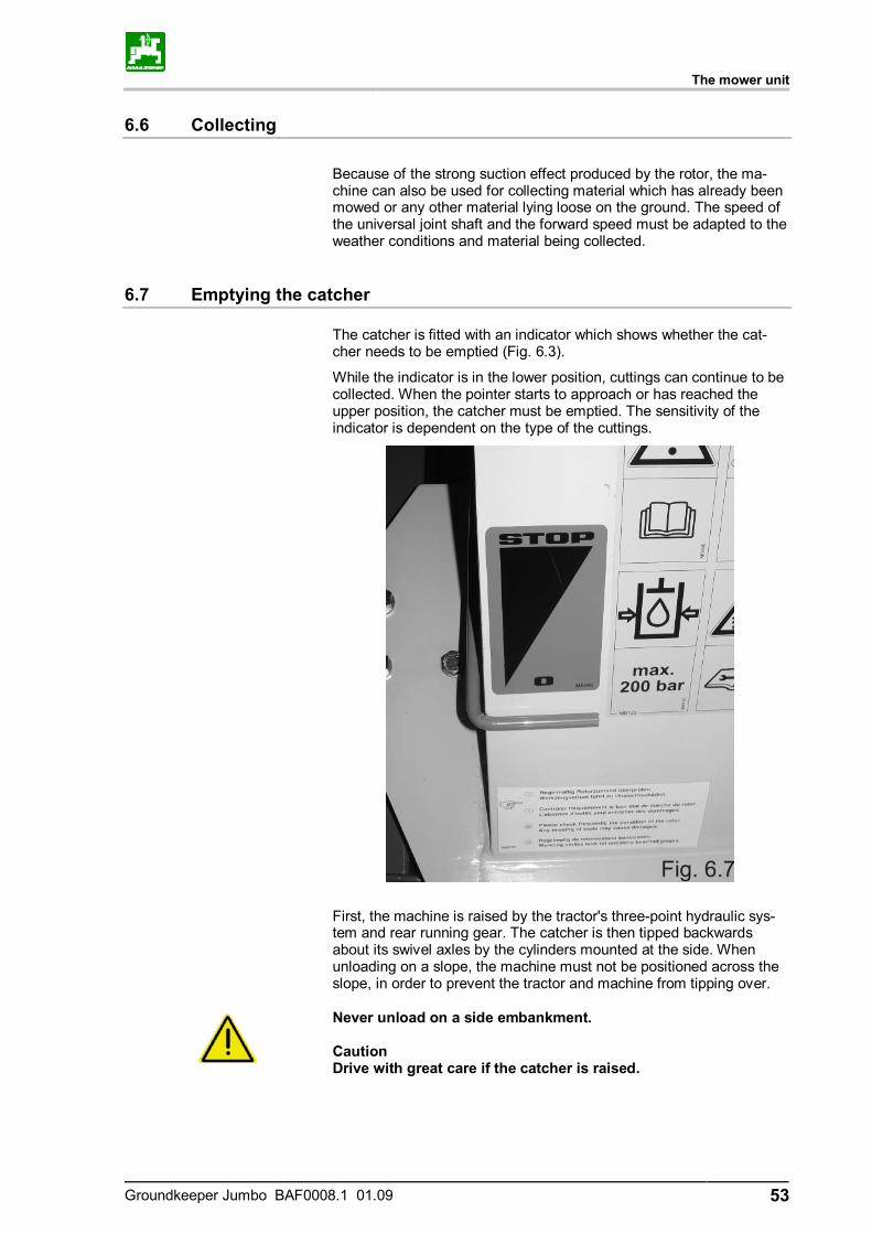
6.7 Emptying the catcher
The catcher is fitted with an indicator which shows whether the cat-cher needs to be emptied (Fig. 6.3).
While the indicator is in the lower position, cuttings can continue to be collected. When the pointer starts to approach or has reached the upper position, the catcher must be emptied. The sensitivity of the indicator is dependent on the type of the cuttings.
First, the machine is raised by the tractor's three-point hydraulic sys-tem and rear running gear. The catcher is then tipped backwards about its swivel axles by the cylinders mounted at the side. When unloading on a slope, the machine must not be positioned across the slope, in order to prevent the tractor and machine from tipping over.
Never unload on a side embankment. Caution Drive with great care if the catcher is raised.
Adjusting the cutting height
54 Groundkeeper Jumbo BAF0008.1 01.09
7 Adjusting the cutting height
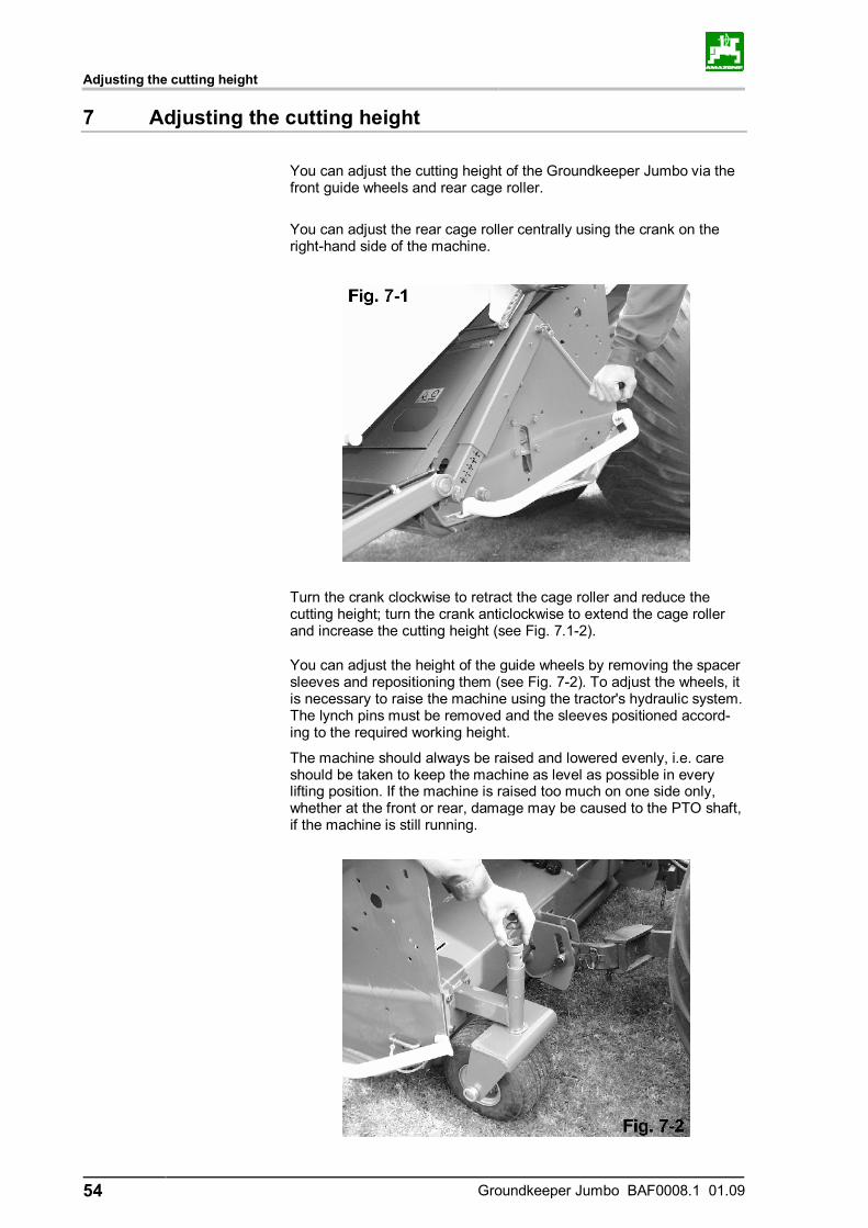
You can adjust the cutting height of the Groundkeeper Jumbo via the front guide wheels and rear cage roller.
You can adjust the rear cage roller centrally using the crank on the right-hand side of the machine.
Turn the crank clockwise to retract the cage roller and reduce the cutting height; turn the crank anticlockwise to extend the cage roller and increase the cutting height (see Fig. 7.1-2).
You can adjust the height of the guide wheels by removing the spacer sleeves and repositioning them (see Fig. 7-2). To adjust the wheels, it is necessary to raise the machine using the tractor's hydraulic system. The lynch pins must be removed and the sleeves positioned accord-ing to the required working height.
The machine should always be raised and lowered evenly, i.e. care should be taken to keep the machine as level as possible in every lifting position. If the machine is raised too much on one side only, whether at the front or rear, damage may be caused to the PTO shaft, if the machine is still running.
Adjusting the cutting height
Groundkeeper Jumbo BAF0008.1 01.09 55
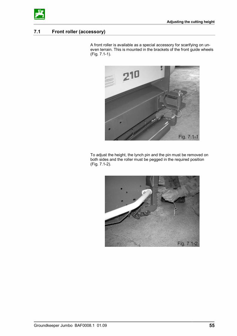
7.1 Front roller (accessory)
A front roller is available as a special accessory for scarifying on un-even terrain. This is mounted in the brackets of the front guide wheels (Fig. 7.1-1).
To adjust the height, the lynch pin and the pin must be removed on both sides and the roller must be pegged in the required position (Fig. 7.1-2).

Cleaning the machine
56 Groundkeeper Jumbo BAF0008.1 01.09
8 Cleaning the machine
The machine can, on occasion, become heavily soiled, especially when mowing and scarifying wet grass which is also sometimes inter-spersed with earth. In such cases, it is recommended to clean the rotor and the catcher intensively with a jet of water.
Maintenance are care
Groundkeeper Jumbo BAF0008.1 01.09 57
9 Maintenance are care
The Groundkeeper Jumbo is largely maintenance free.
9.1 Oil level in the angular gearbox
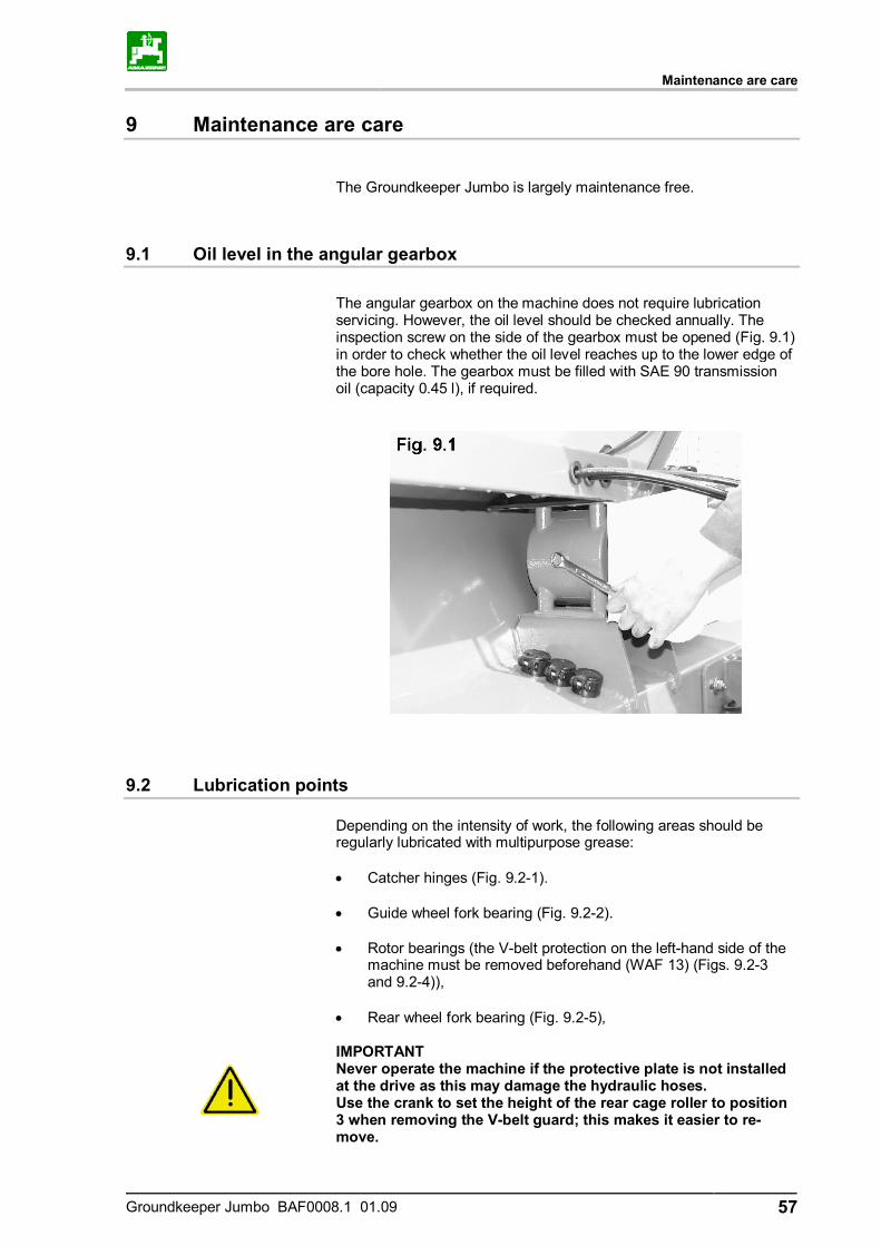
The angular gearbox on the machine does not require lubrication servicing. However, the oil level should be checked annually. The inspection screw on the side of the gearbox must be opened (Fig. 9.1) in order to check whether the oil level reaches up to the lower edge of the bore hole. The gearbox must be filled with SAE 90 transmission oil (capacity 0.45 l), if required.
9.2 Lubrication points
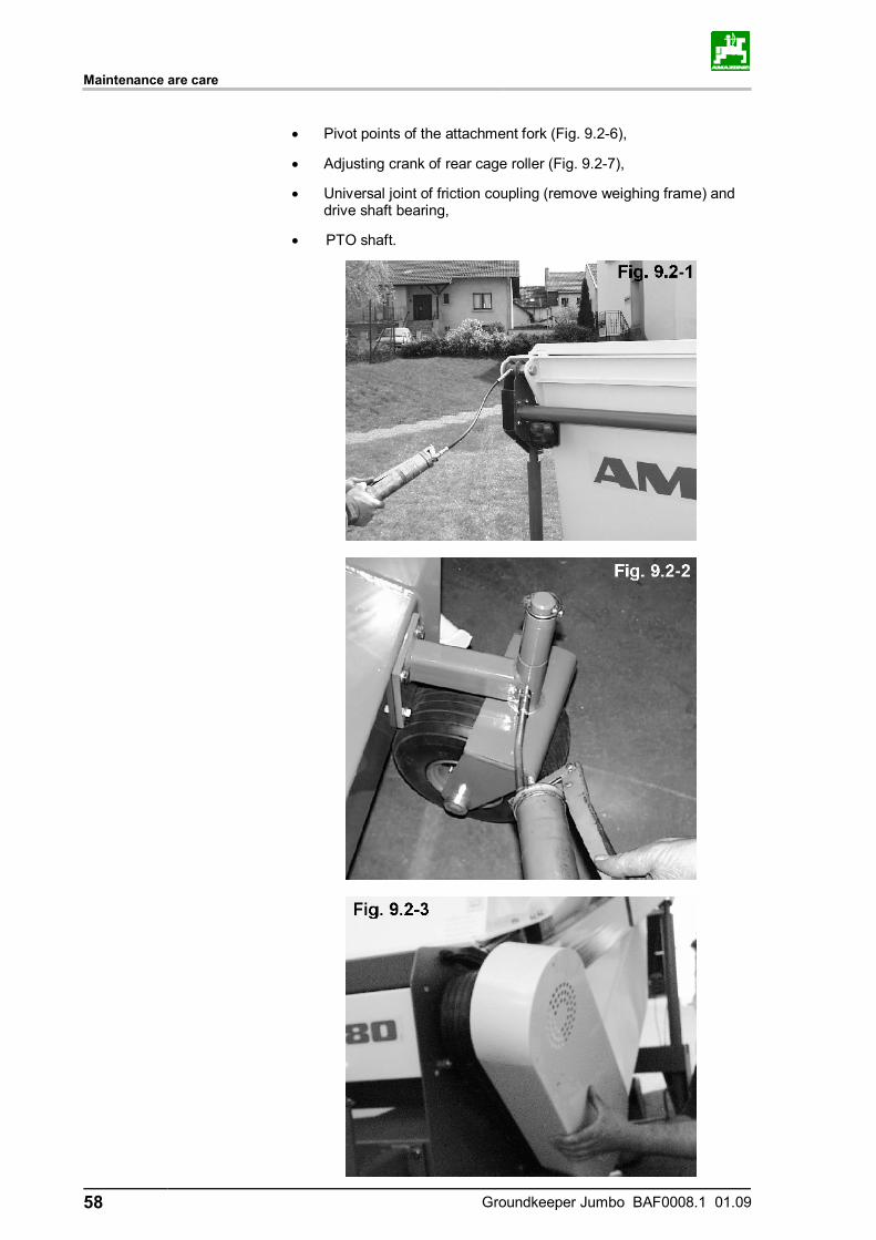
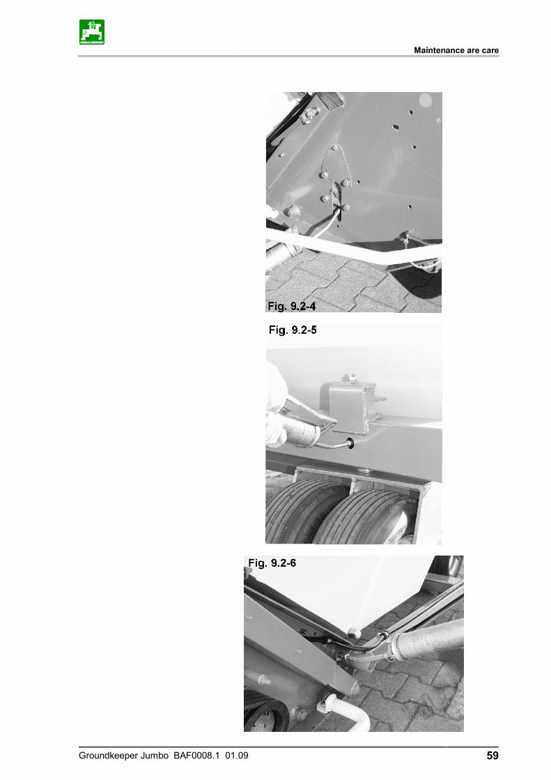
Depending on the intensity of work, the following areas should be regularly lubricated with multipurpose grease: • Catcher hinges (Fig. 9.2-1). • Guide wheel fork bearing (Fig. 9.2-2). • Rotor bearings (the V-belt protection on the left-hand side of the
machine must be removed beforehand (WAF 13) (Figs. 9.2-3 and 9.2-4)),
• Rear wheel fork bearing (Fig. 9.2-5),
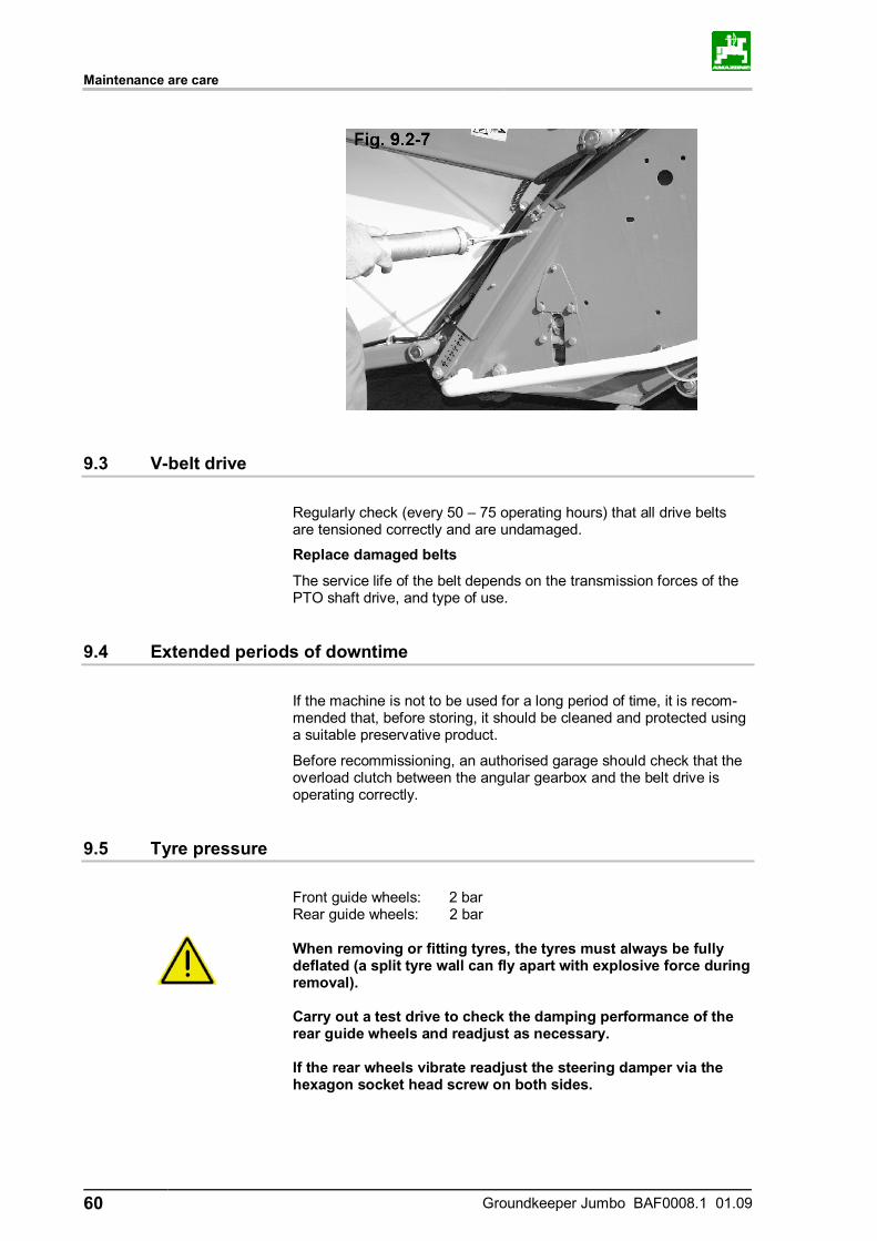
IMPORTANT Never operate the machine if the protective plate is not installed at the drive as this may damage the hydraulic hoses. Use the crank to set the height of the rear cage roller to position 3 when removing the V-belt guard; this makes it easier to re-move.
Maintenance are care
58 Groundkeeper Jumbo BAF0008.1 01.09
• Pivot points of the attachment fork (Fig. 9.2-6),
• Adjusting crank of rear cage roller (Fig. 9.2-7),
• Universal joint of friction coupling (remove weighing frame) and drive shaft bearing,
• PTO shaft.
Maintenance are care
Groundkeeper Jumbo BAF0008.1 01.09 59
Maintenance are care
60 Groundkeeper Jumbo BAF0008.1 01.09
9.3 V-belt drive
Regularly check (every 50 – 75 operating hours) that all drive belts are tensioned correctly and are undamaged.
Replace damaged belts
The service life of the belt depends on the transmission forces of the PTO shaft drive, and type of use.
9.4 Extended periods of downtime
If the machine is not to be used for a long period of time, it is recom-mended that, before storing, it should be cleaned and protected using a suitable preservative product.
Before recommissioning, an authorised garage should check that the overload clutch between the angular gearbox and the belt drive is operating correctly.
9.5 Tyre pressure
Front guide wheels: 2 bar Rear guide wheels: 2 bar
When removing or fitting tyres, the tyres must always be fully deflated (a split tyre wall can fly apart with explosive force during removal). Carry out a test drive to check the damping performance of the rear guide wheels and readjust as necessary. If the rear wheels vibrate readjust the steering damper via the hexagon socket head screw on both sides.
Maintenance are care
Groundkeeper Jumbo BAF0008.1 01.09 61
Transport on public roads
62 Groundkeeper Jumbo BAF0008.1 01.09
10 Transport on public roads
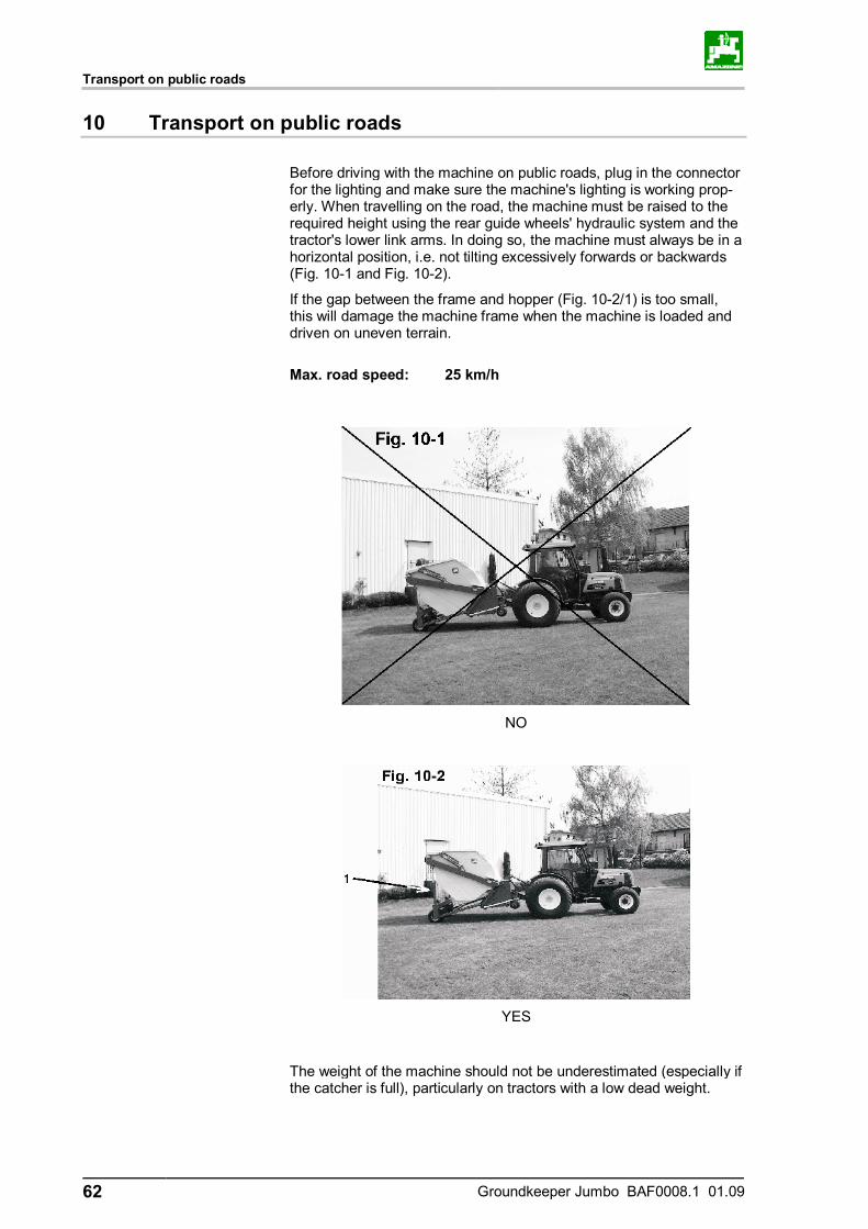
Before driving with the machine on public roads, plug in the connector for the lighting and make sure the machine's lighting is working prop-erly. When travelling on the road, the machine must be raised to the required height using the rear guide wheels' hydraulic system and the tractor's lower link arms. In doing so, the machine must always be in a horizontal position, i.e. not tilting excessively forwards or backwards (Fig. 10-1 and Fig. 10-2).
If the gap between the frame and hopper (Fig. 10-2/1) is too small, this will damage the machine frame when the machine is loaded and driven on uneven terrain.
Max. road speed: 25 km/h
NO
YES
The weight of the machine should not be underestimated (especially if the catcher is full), particularly on tractors with a low dead weight.
Drawbar (option – GHS-T machine type)
Groundkeeper Jumbo BAF0008.1 01.09 63
11 Drawbar (option – GHS-T machine type)
Observe the safety instructions when coupling and uncoupling. Uncouple machines according to the instructions and only at-tach them to the prescribed equipment. Particular care is required when coupling and uncoupling ma-chines to/from the tractor. Observe max. axle load of tractor.
Observe max. trailer load of tractor.
Observe the technically and legally permissible overall weight.
To remove the machine, follow the above procedure in reverse order.
11.1 Attachment
11.1.1 Coupling and uncoupling the machine
The machine does not have a parking brake.
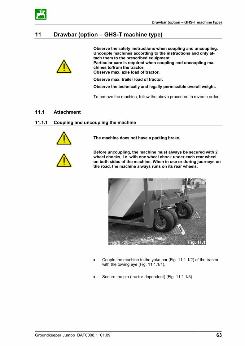
Before uncoupling, the machine must always be secured with 2 wheel chocks, i.e. with one wheel chock under each rear wheel on both sides of the machine. When in use or during journeys on the road, the machine always runs on its rear wheels.
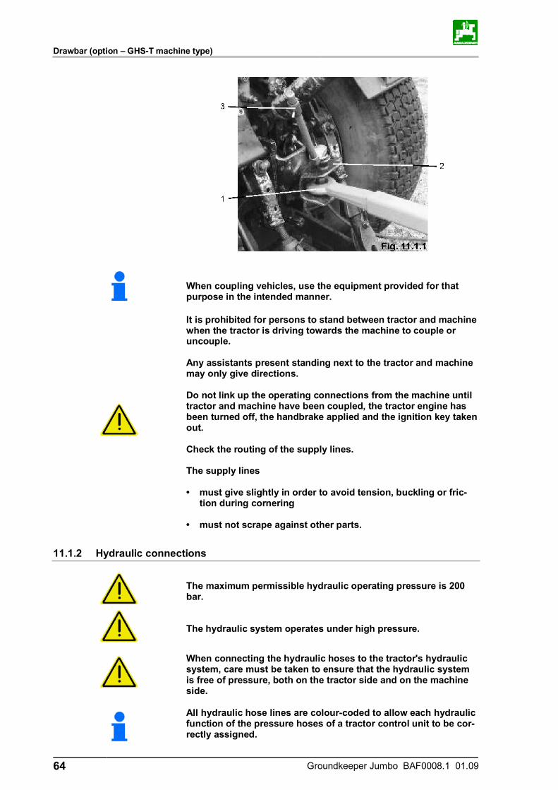
• Couple the machine to the yoke bar (Fig. 11.1.1/2) of the tractor with the towing eye (Fig. 11.1.1/1).
• Secure the pin (tractor-dependent) (Fig. 11.1.1/3).
Drawbar (option – GHS-T machine type)
64 Groundkeeper Jumbo BAF0008.1 01.09
When coupling vehicles, use the equipment provided for that purpose in the intended manner.
It is prohibited for persons to stand between tractor and machine when the tractor is driving towards the machine to couple or uncouple. Any assistants present standing next to the tractor and machine may only give directions. Do not link up the operating connections from the machine until tractor and machine have been coupled, the tractor engine has been turned off, the handbrake applied and the ignition key taken out. Check the routing of the supply lines. The supply lines • must give slightly in order to avoid tension, buckling or fric-
tion during cornering • must not scrape against other parts.
11.1.2 Hydraulic connections
The maximum permissible hydraulic operating pressure is 200 bar.
The hydraulic system operates under high pressure.
When connecting the hydraulic hoses to the tractor's hydraulic system, care must be taken to ensure that the hydraulic system is free of pressure, both on the tractor side and on the machine side.
All hydraulic hose lines are colour-coded to allow each hydraulic function of the pressure hoses of a tractor control unit to be cor-rectly assigned.
Drawbar (option – GHS-T machine type)
Groundkeeper Jumbo BAF0008.1 01.09 65
Hydraulic connections:
Plug hydraulic hose lines into the appropriate connections.
11.1.2.1 Electrically-controlled hydraulic block
Control unit Functions Hose mark-ing
1 – permanent pressure connection
- all 1 x red
2 – free return - all 2 x red
11.1.2.2 Standard hydraulic system
Control unit Functions Hose mark-ing
1 – single-acting - raise the front of the machine unmarked (swivel drawbar)
2 – double-acting - lower the rear of the machine 1 x green - raise the rear of the machine 2 x green
3 – double-acting - lower hopper 1 x yellow - tilt hopper 2 x yellow
The maximum permissible oil back-pressure is 1.5 bar. You should therefore connect the oil return to a pressure free oil return flow with a large plug coupling and not the tractor control unit.
WARNING:
Use only DN16 lines for the oil return and keep the return lines short.
Pressurise the hydraulic system only when the free return has been correctly coupled.
Install the coupling union (supplied) on the pressure free oil re-turn flow.
The hydraulic oil must not become too hot when the machine is in operation. High flow rates in conjunction with small oil tanks tend to cause the temperature of the hydraulic fluid to increase rapidly. The capacity of the oil tank should be at least twice the flow rate. If the temperature rises too quickly, have a specialist workshop install an oil cooler.
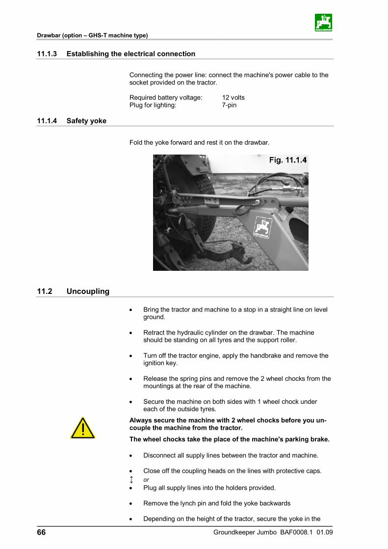
Drawbar (option – GHS-T machine type)
66 Groundkeeper Jumbo BAF0008.1 01.09
11.1.3 Establishing the electrical connection
Connecting the power line: connect the machine's power cable to the socket provided on the tractor. Required battery voltage: 12 volts Plug for lighting: 7-pin
11.1.4 Safety yoke
Fold the yoke forward and rest it on the drawbar.
11.2 Uncoupling
• Bring the tractor and machine to a stop in a straight line on level ground.
• Retract the hydraulic cylinder on the drawbar. The machine
should be standing on all tyres and the support roller. • Turn off the tractor engine, apply the handbrake and remove the
ignition key. • Release the spring pins and remove the 2 wheel chocks from the
mountings at the rear of the machine. • Secure the machine on both sides with 1 wheel chock under
each of the outside tyres.
Always secure the machine with 2 wheel chocks before you un-couple the machine from the tractor.
The wheel chocks take the place of the machine's parking brake.
• Disconnect all supply lines between the tractor and machine. • Close off the coupling heads on the lines with protective caps. ↕ or • Plug all supply lines into the holders provided. • Remove the lynch pin and fold the yoke backwards • Depending on the height of the tractor, secure the yoke in the

Drawbar (option – GHS-T machine type)
Groundkeeper Jumbo BAF0008.1 01.09 67
anchor with the lynch pin (Fig. 11.2)
The machine must only be set down on level and firm ground.
Before detaching the machine, check that the coupling point is not under load. - Uncouple the drawbar.
- Drive the tractor away.
When driving the tractor away, there must be nobody present between tractor and machine.
Always use the retaining bracket for the drawbar. Without the retaining bracket, the drawbar would fall to the ground, thereby creating a risk of injury.

Transport on public roads and unclassified roads
68 Groundkeeper Jumbo BAF0008.1 01.09
12 Transport on public roads and unclassified roads
Max. road speed = 25 km/h.
Road transport position: fully extend hydraulic cylinder of drawbar and close stop tap, extend rear hydraulic cylinder until a ground clearance of roughly 150 mm exists.
When driving on public and unclassified roads the tractor and machine must comply with the national road traffic regulations (StVZO and StVO in Germany) and the relevant accident preven-tion regulations.
The vehicle keeper and driver are responsible for ensuring that the statutory regulations are complied with. Furthermore, the instructions in this section must be followed prior to setting off and when on the road. The regulations for prevention of road traffic accidents must be complied with. Comply with the permissible axle loads, load capacities of tyres, drawbar load of tractor lower link and overall tractor weight. The front axle load of the tractor must be at least 20% of the un-laden weight of the tractor when transporting the machine as otherwise a sufficient margin of safety no longer exists for steer-ing the tractor. The maximum speed of the machine is 25 km/h. The machine must always be driven at much lower speeds especially when travelling on poor roads and unclassified roads. The weight of the machine affects the driving dynamics as well as the steering and braking capability. The large overhang and inertia of the machine must be taken into consideration during cornering. Do not ride on the machine or use it as a means of transport. Always check that all traffic safety kits are functional or mount suitable accessory parts (e.g. protective tarpaulins) once the machine is in the transport position.
The control lever of the tractor's hydraulic system must be loc-ked to prevent the machine from folding out and lowering when travelling on the road with the machine lifted out.
Before setting off: check the tyre air pressure of the wheels on the running gear.
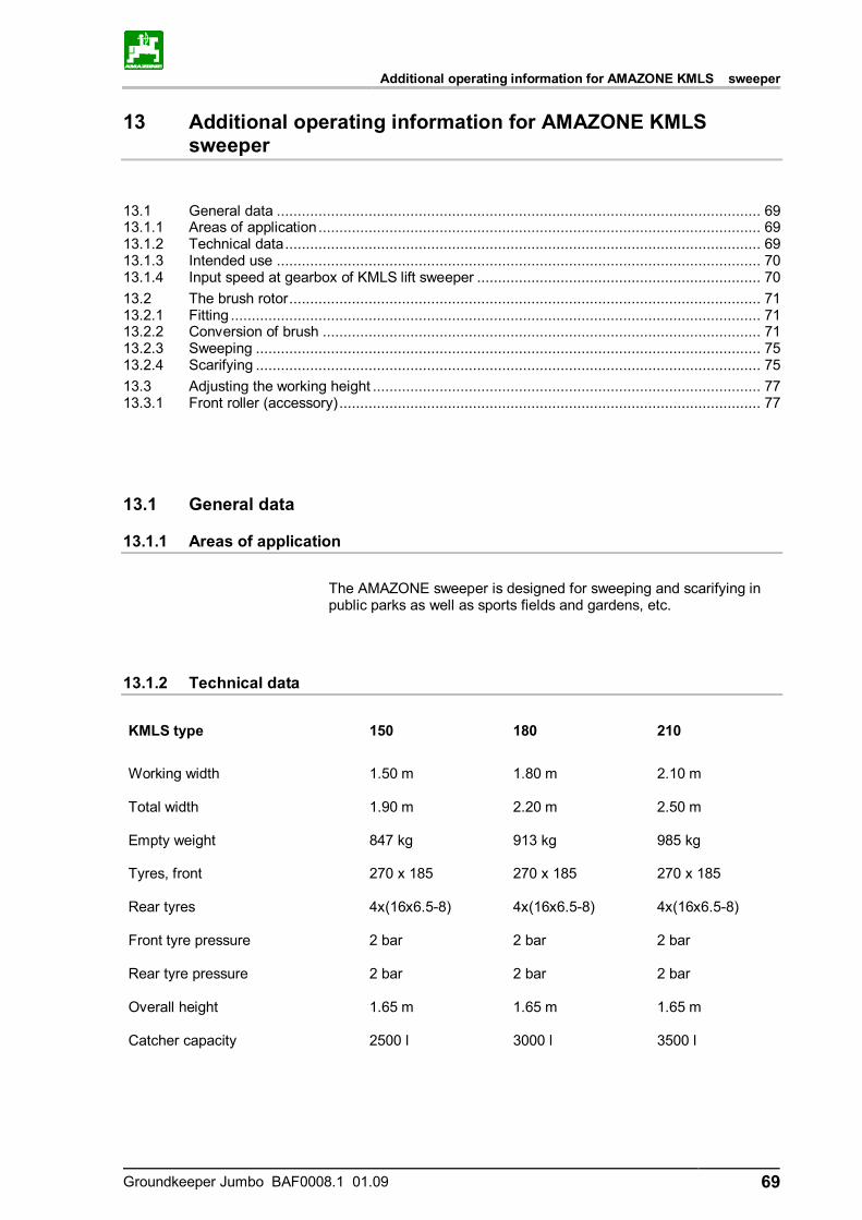
Additional operating information for AMAZONE KMLS sweeper
Groundkeeper Jumbo BAF0008.1 01.09 69
13 Additional operating information for AMAZONE KMLS sweeper
13.1 General data .................................................................................................................... 69 13.1.1 Areas of application.......................................................................................................... 69 13.1.2 Technical data.................................................................................................................. 69 13.1.3 Intended use .................................................................................................................... 70 13.1.4 Input speed at gearbox of KMLS lift sweeper .................................................................... 70 13.2 The brush rotor................................................................................................................. 71 13.2.1 Fitting ............................................................................................................................... 71 13.2.2 Conversion of brush ......................................................................................................... 71 13.2.3 Sweeping ......................................................................................................................... 75 13.2.4 Scarifying ......................................................................................................................... 75 13.3 Adjusting the working height ............................................................................................. 77 13.3.1 Front roller (accessory)..................................................................................................... 77
13.1 General data
13.1.1 Areas of application
The AMAZONE sweeper is designed for sweeping and scarifying in public parks as well as sports fields and gardens, etc.
13.1.2 Technical data
KMLS type 150 180 210
Working width 1.50 m 1.80 m 2.10 m Total width 1.90 m 2.20 m 2.50 m Empty weight 847 kg 913 kg 985 kg Tyres, front 270 x 185 270 x 185 270 x 185 Rear tyres 4x(16x6.5-8) 4x(16x6.5-8) 4x(16x6.5-8) Front tyre pressure 2 bar 2 bar 2 bar Rear tyre pressure 2 bar 2 bar 2 bar Overall height 1.65 m 1.65 m 1.65 m Catcher capacity 2500 l 3000 l 3500 l
Additional operating information for AMAZONE KMLS sweeper
70 Groundkeeper Jumbo BAF0008.1 01.09
13.1.3 Intended use
The Amazone sweeper is designed exclusively to carry out conven-tional maintenance tasks in grassed open areas and parks (intended use). Any use which goes beyond these limits is not regarded as the in-tended use. The manufacturer is not liable for any damages which may result from such use. The risk involved in such use is borne solely by the user. Intended use also includes compliance with instructions specified by the manufacturer concerning operation, servicing and maintenance as well as the exclusive use of genuine AMAZONE spare parts. The AMAZONE sweeper may only be used, serviced and maintained by persons who are familiar with the machine and who have received instruction concerning the risks involved. All relevant accident prevention regulations and any other generally recognised rules concerning safety, occupational health and traffic laws must be observed and the safety instructions on the labels at-tached to the machine must be strictly followed. Any unauthorised modification of the machine will automatically render all warranty claims against the manufacturer for resulting damage invalid.
13.1.4 Input speed at gearbox of KMLS lift sweeper
The gearbox of the KMLS lift sweeper is equipped with a universal joint shaft connection. The machine must be driven with a maximum drive rev. speed of 540 rpm for sweeping and a maximum drive rev. speed of 1000 rpm for scarifying:
Drive rev. speed for sweeping n = 540 rpm Drive rev. speed for scarifying n = 100 rpm
Drive speeds higher than those specified will cause the rotor to turn at significantly higher speeds. In extreme cases, this may cause blades or brushes to detach which could be dangerous for operating personnel.
Warranty claims for damage which can be traced back to an ex-cessively high drive speed of the universal joint shaft will not be recognised.
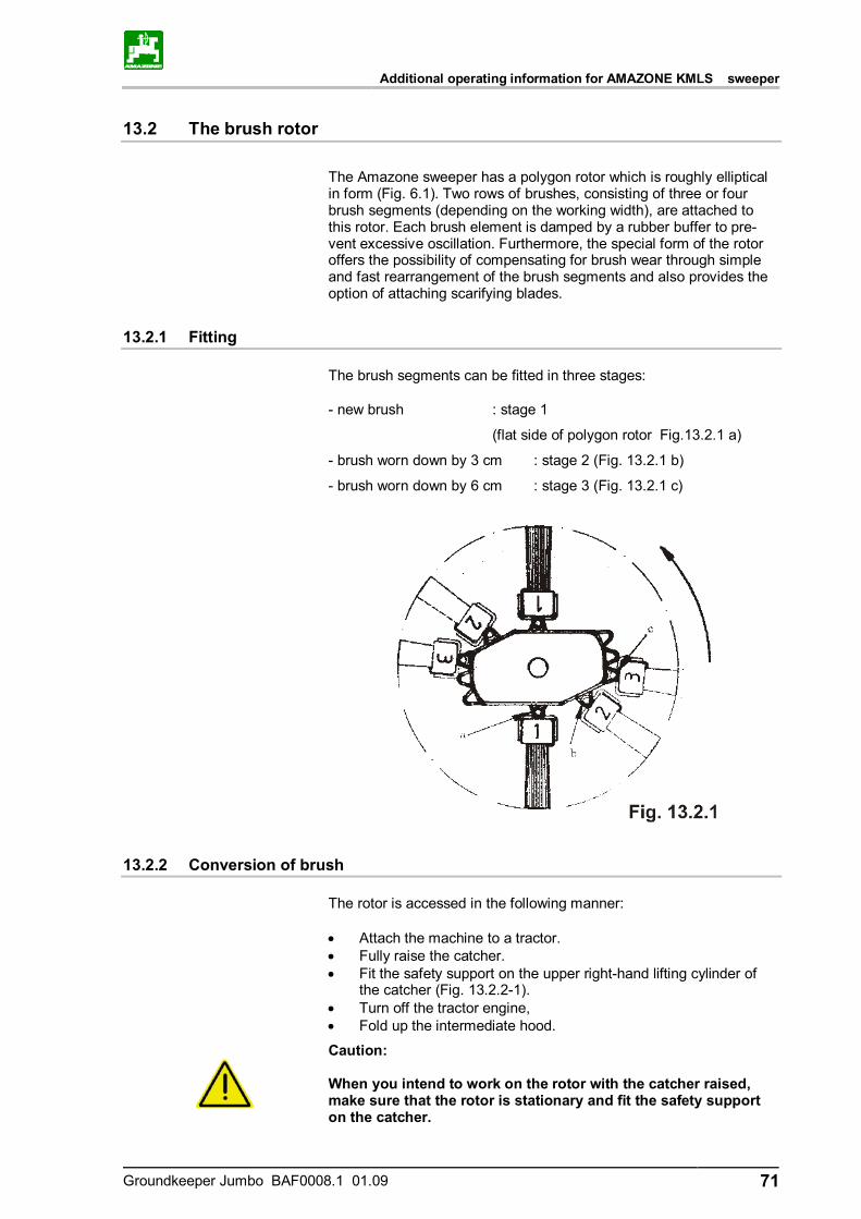
Additional operating information for AMAZONE KMLS sweeper
Groundkeeper Jumbo BAF0008.1 01.09 71
13.2 The brush rotor
The Amazone sweeper has a polygon rotor which is roughly elliptical in form (Fig. 6.1). Two rows of brushes, consisting of three or four brush segments (depending on the working width), are attached to this rotor. Each brush element is damped by a rubber buffer to pre-vent excessive oscillation. Furthermore, the special form of the rotor offers the possibility of compensating for brush wear through simple and fast rearrangement of the brush segments and also provides the option of attaching scarifying blades.
13.2.1 Fitting
The brush segments can be fitted in three stages:
- new brush : stage 1
(flat side of polygon rotor Fig.13.2.1 a)
- brush worn down by 3 cm : stage 2 (Fig. 13.2.1 b)
- brush worn down by 6 cm : stage 3 (Fig. 13.2.1 c)
13.2.2 Conversion of brush
The rotor is accessed in the following manner: • Attach the machine to a tractor. • Fully raise the catcher. • Fit the safety support on the upper right-hand lifting cylinder of
the catcher (Fig. 13.2.2-1). • Turn off the tractor engine, • Fold up the intermediate hood.
Caution: When you intend to work on the rotor with the catcher raised, make sure that the rotor is stationary and fit the safety support on the catcher.
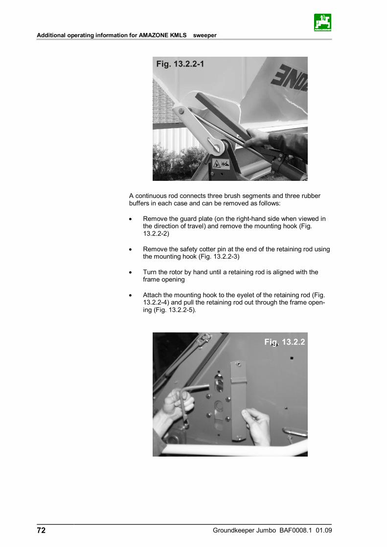
Additional operating information for AMAZONE KMLS sweeper
72 Groundkeeper Jumbo BAF0008.1 01.09
A continuous rod connects three brush segments and three rubber buffers in each case and can be removed as follows: • Remove the guard plate (on the right-hand side when viewed in
the direction of travel) and remove the mounting hook (Fig. 13.2.2-2)
• Remove the safety cotter pin at the end of the retaining rod using
the mounting hook (Fig. 13.2.2-3) • Turn the rotor by hand until a retaining rod is aligned with the
frame opening • Attach the mounting hook to the eyelet of the retaining rod (Fig.
13.2.2-4) and pull the retaining rod out through the frame open-ing (Fig. 13.2.2-5).
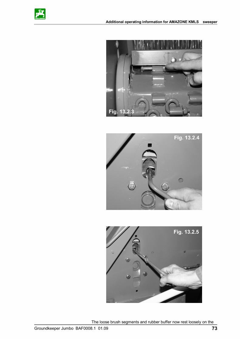
Additional operating information for AMAZONE KMLS sweeper
Groundkeeper Jumbo BAF0008.1 01.09 73
The loose brush segments and rubber buffer now rest loosely on the

Additional operating information for AMAZONE KMLS sweeper
74 Groundkeeper Jumbo BAF0008.1 01.09
rotor and can be brought into the required position. Follow the above procedure in the reverse order to fasten the brush. Care must be ta-ken to ensure that the rod is also inserted through the rubber buffer. To mount the brushes in the second stage, the diagonal rubber buff-ers supplied with the machine must be mounted as shown in Fig. 13.2.2-6.
Caution: Three or four brush segments must be mounted in a row in each case. The brush rows must always be arranged symmetrically, i.e. op-posite one another. The brush segments are equipped on one side with a guard strip (Fig. 13.2.2-7). Make sure that these strips are always arranged in the direction of rotation of the rotor. The brush segments must always be located together with a rubber buffer. Only use the special cotter pins mounted at the factory to secure the brush rods.
Hint Make absolutely sure that the same brush segments occupy all positions on the rotor. If brushes are missing, damaged or have
Diagonal rubber buffer
Direction of rotation
Direction of travel
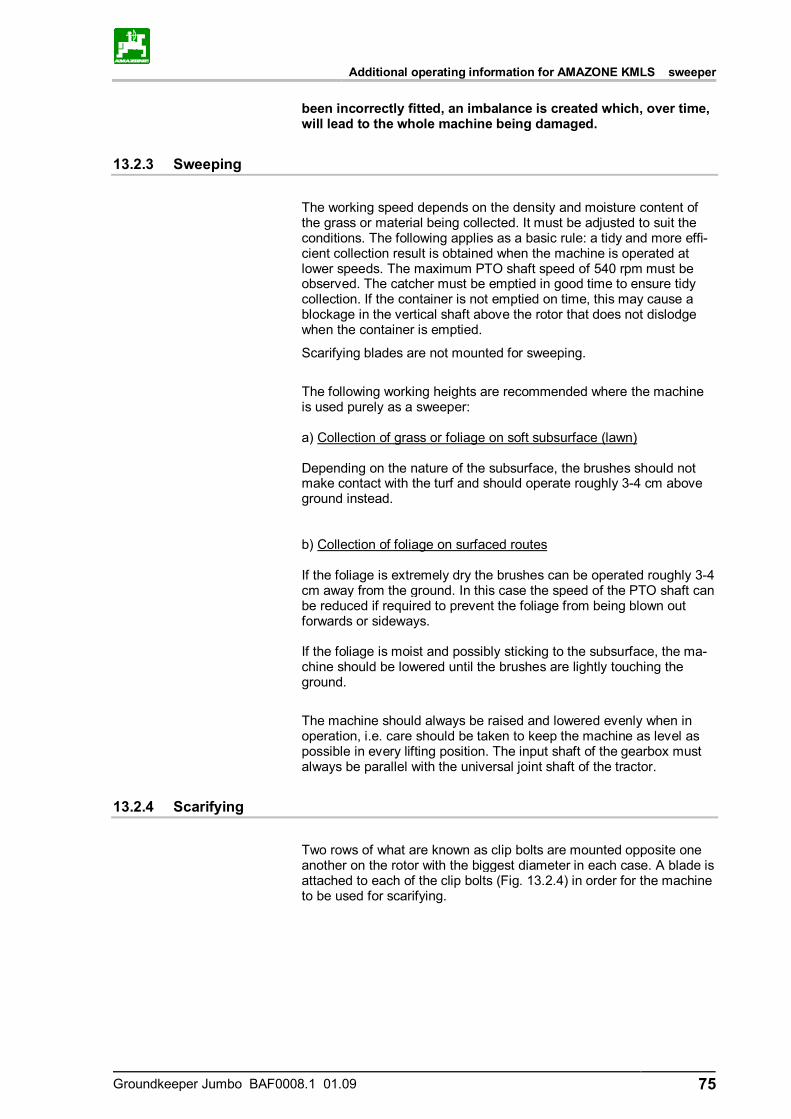
Additional operating information for AMAZONE KMLS sweeper
Groundkeeper Jumbo BAF0008.1 01.09 75
been incorrectly fitted, an imbalance is created which, over time, will lead to the whole machine being damaged.
13.2.3 Sweeping
The working speed depends on the density and moisture content of the grass or material being collected. It must be adjusted to suit the conditions. The following applies as a basic rule: a tidy and more effi-cient collection result is obtained when the machine is operated at lower speeds. The maximum PTO shaft speed of 540 rpm must be observed. The catcher must be emptied in good time to ensure tidy collection. If the container is not emptied on time, this may cause a blockage in the vertical shaft above the rotor that does not dislodge when the container is emptied.
Scarifying blades are not mounted for sweeping.
The following working heights are recommended where the machine is used purely as a sweeper: a) Collection of grass or foliage on soft subsurface (lawn) Depending on the nature of the subsurface, the brushes should not make contact with the turf and should operate roughly 3-4 cm above ground instead. b) Collection of foliage on surfaced routes If the foliage is extremely dry the brushes can be operated roughly 3-4 cm away from the ground. In this case the speed of the PTO shaft can be reduced if required to prevent the foliage from being blown out forwards or sideways. If the foliage is moist and possibly sticking to the subsurface, the ma-chine should be lowered until the brushes are lightly touching the ground.
The machine should always be raised and lowered evenly when in operation, i.e. care should be taken to keep the machine as level as possible in every lifting position. The input shaft of the gearbox must always be parallel with the universal joint shaft of the tractor.
13.2.4 Scarifying
Two rows of what are known as clip bolts are mounted opposite one another on the rotor with the biggest diameter in each case. A blade is attached to each of the clip bolts (Fig. 13.2.4) in order for the machine to be used for scarifying.
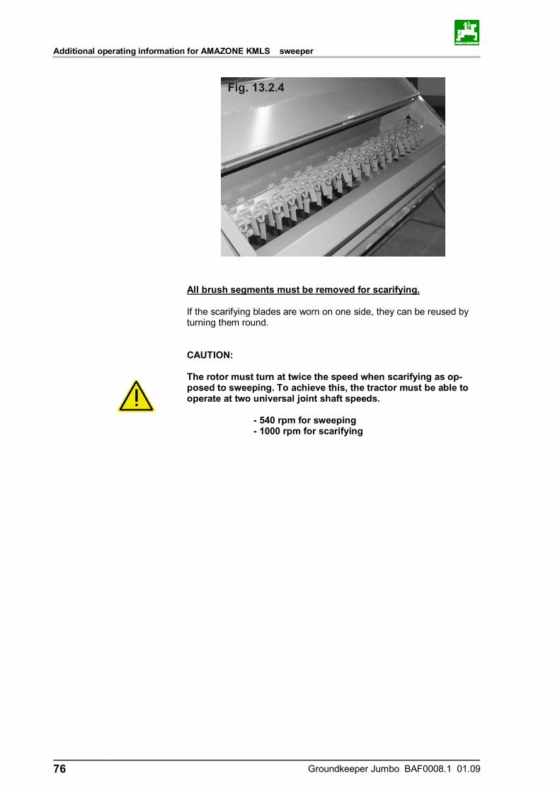
Additional operating information for AMAZONE KMLS sweeper
76 Groundkeeper Jumbo BAF0008.1 01.09
All brush segments must be removed for scarifying. If the scarifying blades are worn on one side, they can be reused by turning them round.
CAUTION: The rotor must turn at twice the speed when scarifying as op-posed to sweeping. To achieve this, the tractor must be able to operate at two universal joint shaft speeds. - 540 rpm for sweeping - 1000 rpm for scarifying
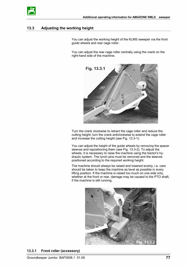
Additional operating information for AMAZONE KMLS sweeper
Groundkeeper Jumbo BAF0008.1 01.09 77
13.3 Adjusting the working height
You can adjust the working height of the KLMS sweeper via the front guide wheels and rear cage roller.
You can adjust the rear cage roller centrally using the crank on the right-hand side of the machine.
Turn the crank clockwise to retract the cage roller and reduce the cutting height; turn the crank anticlockwise to extend the cage roller and increase the cutting height (see Fig. 13.3-1).
You can adjust the height of the guide wheels by removing the spacer sleeves and repositioning them (see Fig. 13.3-2). To adjust the wheels, it is necessary to raise the machine using the tractor's hy-draulic system. The lynch pins must be removed and the sleeves positioned according to the required working height.
The machine should always be raised and lowered evenly, i.e. care should be taken to keep the machine as level as possible in every lifting position. If the machine is raised too much on one side only, whether at the front or rear, damage may be caused to the PTO shaft, if the machine is still running.
13.3.1 Front roller (accessory)
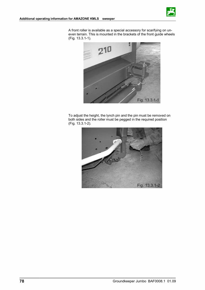
Additional operating information for AMAZONE KMLS sweeper
78 Groundkeeper Jumbo BAF0008.1 01.09
A front roller is available as a special accessory for scarifying on un-even terrain. This is mounted in the brackets of the front guide wheels (Fig. 13.3.1-1).
To adjust the height, the lynch pin and the pin must be removed on both sides and the roller must be pegged in the required position (Fig. 13.3.1-2).

Groundkeeper Jumbo BAF0008.1 01.09 79
NOTES
............................................................................................................................................................
............................................................................................................................................................
............................................................................................................................................................
............................................................................................................................................................
............................................................................................................................................................
............................................................................................................................................................
............................................................................................................................................................
............................................................................................................................................................
............................................................................................................................................................
............................................................................................................................................................
............................................................................................................................................................
............................................................................................................................................................
............................................................................................................................................................
............................................................................................................................................................
............................................................................................................................................................
............................................................................................................................................................
............................................................................................................................................................
............................................................................................................................................................
............................................................................................................................................................
............................................................................................................................................................
............................................................................................................................................................
............................................................................................................................................................
............................................................................................................................................................
............................................................................................................................................................
............................................................................................................................................................
............................................................................................................................................................
............................................................................................................................................................
............................................................................................................................................................
............................................................................................................................................................
............................................................................................................................................................
............................................................................................................................................................
............................................................................................................................................................
............................................................................................................................................................
............................................................................................................................................................
............................................................................................................................................................
............................................................................................................................................................
............................................................................................................................................................
............................................................................................................................................................
............................................................................................................................................................

80 Groundkeeper Jumbo BAF0008.1 01.09
H. DREYER GmbH & Co. KG
Postfach 51 D-49202 Hasbergen-Gaste Germany
Phone: +49 5405 501-0 Fax: +49 5405 501-234 e-mail: [email protected] http:// www.amazone.de
az S.A. FORBACH
17, rue de la Verrerie – BP 90106 F-57602 FORBACH Cedex France
Phone: +33 (0)3 87 84 65 70 Fax: +33 (0)3 87 84 65 71 e-mail: [email protected] http:// www.amazone.fr
BBG Bodenbearbeitungsgeräte Leipzig GmbH & Co.KG
Rippachtalstr. 10 D-04249 Leipzig Germany
Branch plants: D-27794 Hude • D-04249 Leipzig, Germany • F-
57602 Forbach, France, Subsidiary plants in England and France
Manufacturers of mineral fertiliser spreaders, field sprayers, sowing machines, soil cultivation ma-chines, multipurpose warehouses and communal units