Embed Size (px)
Citation preview

MH-SERIES SIGMA III POSITIONERMANUAL for DX100
Upon receipt of the product and prior to initial operation, read these instructions thoroughly and retain for future reference.
Part Number: 156488-1CDRevision: 1
MOTOMAN INSTRUCTIONS
MOTOMAN INSTRUCTIONSDX100 INSTRUCTIONSDX100OPERATOR’S MANUALDX100 MAINTENANCE MANUAL
The DX100 operator’s manual above corresponds to specific usage. Be sure to use the appropriate manual.
MANUAL NO.
1156488-1CD 1/92

156488-1CD
MH-Series Positioner
MANDATORY
General items related to safety are listed in Section 2 of the DX100 Controller Manual. To ensure correct and safe operation, carefully read the DX100 Controller Manual before reading this manual.
CAUTION
• The drawings and photos in this manual are representative examples, and differences may exist between them and the delivered product.
• YASKAWA may modify this model without notice when necessary due to product improvements, modifications, or changes in specifications.
• If such a modification is made, the manual number will also be revised.
• If your copy of the manual is damaged or lost, contact a YASKAWA representative to order a new copy. The representatives are listed on the back cover. Be sure to tell the representative the manual number listed on the front cover.
• YASKAWA is not responsible for incidents arising from unauthorized modification of its products. Unauthorized modification voids the products warranty.
ii
156488-1CD 2/92
156488-1CD
MH-Series Positioner
Notes for Safe OperationRead this manual carefully before installation, operation, maintenance, or inspection of the MH-Series Positioner.
In this manual, the Notes for Safe Operation are classified as “WARNING,” “CAUTION,” “MANDATORY,” or “PROHIBITED.”
Even items described as “CAUTION” may result in a serious accident in some situations. At any rate, be sure to follow these important items.
WARNINGIndicates a potentially hazardous situation which, if not avoided, could result in death or serious injury to personnel.
CAUTIONIndicates a potentially hazardous situation which, if not avoided, could result in minor or moderate injury to personnel and damage to equipment. It may also be used to alert against unsafe practices.
MANDATORYAlways be sure to follow explicitly the items listed under this heading.
PROHIBITEDMust never be performed.
NOTETo ensure safe and efficient operation at all times, be sure to follow all instructions, even if not designated as "CAUTION" and "WARNING."
iii
156488-1CD 3/92

156488-1CD
MH-Series Positioner
WARNING
• Before operating the MH-Series Positioner, check that servo power is turned OFF by pressing the EMERGENCY STOP buttons on the operator station or Programming Pendant (refer to Figure 1). When servo power is turned OFF, the SERVO ON LED on the Programming Pendant is turned OFF.
Injury or damage to machinery may result if the Emergency Stop circuit cannot stop the positioner during an emergency. The positioner should not be used if the EMERGENCY STOP buttons do not function.
Figure 1: EMERGENCY STOP Button
• Release the EMERGENCY STOP button (refer to Figure 2). Once this button is released, clear the cell of all items which could interfere with the operation of the positioner then, turn servo power ON.
Injury may result from unintentional or unexpected positioner motion.
Figure 2 : Release of EMERGENCY STOP Button
TURN
• Observe the following precautions when performing teaching operations within the working envelope of the positioner:
– View the positioner from the front whenever possible.
– Always follow the predetermined operating procedure.
– Ensure that there is a safe place to retreat to in case of emergency.
Improper or unintended manipulator operation may result in injury.
• Confirm that no person is present in the working envelope of the positioner and that you are in a safe location before:
– Turning on the power for the DX100 controller.
– Moving the positioner with the Programming Pendant.
– Running the system in the check mode.
– Performing automatic operations.
Injury may result if anyone enters the working envelope of the positioner during operation. Always press an EMERGENCY STOP button immediately if there is a problem. The EMERGENCY STOP buttons are located on the operator station and on the Programming Pendant.
iv
156488-1CD 4/92
156488-1CD
MH-Series Positioner
Definition of Terms Used Often in This ManualThe positioner usually consists of the controller, the Programming Pendant, and supply cables.
In this manual, the equipment is designated as follows:
CAUTION
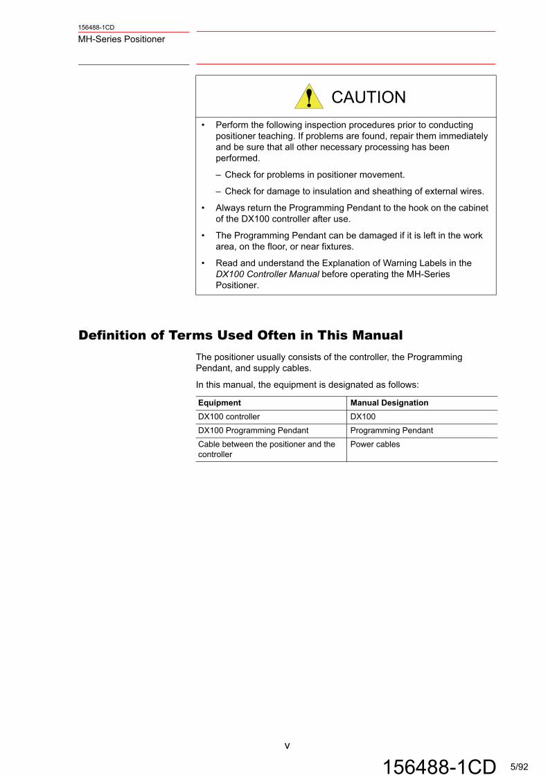
• Perform the following inspection procedures prior to conducting positioner teaching. If problems are found, repair them immediately and be sure that all other necessary processing has been performed.
– Check for problems in positioner movement.
– Check for damage to insulation and sheathing of external wires.
• Always return the Programming Pendant to the hook on the cabinet of the DX100 controller after use.
• The Programming Pendant can be damaged if it is left in the work area, on the floor, or near fixtures.
• Read and understand the Explanation of Warning Labels in the DX100 Controller Manual before operating the MH-Series Positioner.
Equipment Manual Designation
DX100 controller DX100
DX100 Programming Pendant Programming Pendant
Cable between the positioner and the controller
Power cables
v
156488-1CD 5/92
156488-1CD
MH-Series Positioner
1 Introduction.......................................................................................................... 1-1
1.1 About this Document ................................................................................. 1-1
1.2 System Overview ...................................................................................... 1-1
1.2.1 MotoMount™ ................................................................................. 1-1
1.3 System Layout .......................................................................................... 1-2
1.3.1 Type I ............................................................................................ 1-2
1.4 Type II ....................................................................................................... 1-3
1.5 Customer Support Information .................................................................. 1-3
2 Equipment Description ....................................................................................... 2-1
2.1 General Information .................................................................................. 2-1
2.2 MH-Series SIGMA III Positioner Manual Drive Assembly – Type I ........... 2-1
2.2.1 MH-Series SIGMA III Positioner Manual, Type I – Specifications . 2-2
2.3 ..........MH-Series SIGMA III Positioner Manual Drive Assembly – Type II 2-3
2.3.1 MH-Series SIGMA III Positioner Manual, Type II – Specifications 2-4
2.4 MotoMount™ ............................................................................................ 2-5
3 Installation............................................................................................................ 3-1
3.1 Materials Required .................................................................................... 3-1
3.1.1 Customer-Supplied Items .............................................................. 3-1
3.1.2 List of Tools ................................................................................... 3-1
3.2 Installing the MH-Series SIGMA III Positioner Manual Drive – Type I ...... 3-2
3.2.1 Site Preparation ............................................................................. 3-2
3.2.2 Unpacking ..................................................................................... 3-2
3.2.3 Headstock Assembly Mounting Hole Pattern – MH90/180/500/1600 ...................................................................... 3-3
3.2.4 Column Assembly Mounting – Type I Drive Assembly .................. 3-5
3.2.5 Connecting the Cables .................................................................. 3-7
3.2.6 Home Position ............................................................................... 3-7
vi
156488-1CD 6/92

156488-1CD
MH-Series Positioner
3.3 Installing the MH-Series SIGMA III Positioner Manual Drive – Type II .....3-8
3.3.1 Site Preparation .............................................................................3-8
3.3.2 Unpacking ......................................................................................3-8
3.3.3 Floor Mounting – Type II ................................................................3-9
3.3.4 Connecting the Cables .................................................................3-10
3.3.5 Connection to Motoman Controller ..............................................3-11
3.3.6 Home Position ..............................................................................3-11
3.4 Tailstock Column Installation ...................................................................3-12
3.4.1 Type I Installation .........................................................................3-12
3.4.2 Type II Installation ........................................................................3-13
3.4.3 Leveling the Tailstock ..................................................................3-14
3.4.4 Tooling Fixture Installation (initial) ...............................................3-17
3.4.5 Tooling Fixture Installation (regular) ............................................3-18
3.4.6 Final Alignment Check .................................................................3-18
3.4.7 Tooling Fixture Removal ..............................................................3-22
3.5 MotoMount Installation ............................................................................3-22
3.5.1 Preparation ..................................................................................3-22
3.5.2 Unpack and Assemble .................................................................3-22
3.5.3 Securing MotoMount Drive Components onto Faceplate ............3-24
3.5.4 Retrofitting Tailstock Assembly ....................................................3-24
3.6 MotoMount HD Adjustments ...................................................................3-25
3.6.1 Allowable Misalignment ...............................................................3-25
3.6.2 Tooling Fixture Installation – MotoMount HD ...............................3-26
3.6.3 Tooling Fixture Removal ..............................................................3-26
3.6.4 Variable Tooling Size Accommodations ......................................3-26
3.7 Conducting a Safety/Operation Check ....................................................3-27
vii
156488-1CD 7/92

156488-1CD
MH-Series Positioner
4 Tooling Recommendations ................................................................................ 4-1
4.1 Headstock Only – Tooling Recommendations .......................................... 4-1
4.1.1 Customer-supplied Tooling Fixture ............................................... 4-2
4.2 Headstock/Tailstock with MotoMount ....................................................... 4-4
4.2.1 Customer-supplied Tooling Fixtures .............................................. 4-4
4.2.2 Multiple Tooling Fixtures ............................................................... 4-4
4.2.3 Specifications ................................................................................ 4-5
5 Maintenance......................................................................................................... 5-1
5.1 Spare Parts ............................................................................................... 5-1
5.2 Servomotor ............................................................................................... 5-2
5.3 Weld Ground Brush Replacement – Type I .............................................. 5-2
5.3.1 MH90/180/500/1600 ...................................................................... 5-2
5.4 Weld Ground Brush Replacement – Type II ............................................. 5-4
5.4.1 MH1200/3100 ................................................................................ 5-4
5.5 Reset Headstock To Home Position ......................................................... 5-7
5.5.1 Homing .......................................................................................... 5-7
5.5.2 MH90/180/500/1600 .................................................................... 5-10
5.5.3 MH1200/3100 .............................................................................. 5-10
5.6 Maintenance Schedule ........................................................................... 5-11
5.6.1 MH-Series SIGMA III Positioner Manual Positioners .................. 5-11
5.6.2 MotoMount .................................................................................. 5-11
5.7 Troubleshooting ...................................................................................... 5-12
5.7.1 MH-Series SIGMA III Positioner Manual Positioners .................. 5-12
5.7.2 MotoMount .................................................................................. 5-12
viii
156488-1CD 8/92

156488-1CD
MH-Series Positioner
A Performance Charts ........................................................................................... A-1
A.1 MH-Series SIGMA III Positioner Manual Drive Assemblies ..................... A-1
A.1.1 MH90 ............................................................................................ A-1
A.1.2 MH180 .......................................................................................... A-2
A.1.3 MH500 .......................................................................................... A-3
A.1.4 MH1200 ........................................................................................ A-4
A.1.5 MH1600 ........................................................................................ A-5
A.1.6 MH3100 ........................................................................................ A-6
B Illustrated Parts list ............................................................................................ B-1
B.1 Introduction .............................................................................................. B-1
B.1.1 Contents ....................................................................................... B-1
B.1.2 Parts List ....................................................................................... B-1
B.1.3 Symbols and Abbreviations .......................................................... B-2
ix
156488-1CD 9/92

1 Introduction1.1 About this Document
156488-1CD
MH-Series Positioner
1 Introduction
1.1 About this Document
This manual provides information for Yaskawa Motoman® MH-Series SIGMA III Positioner Manual Type I and Type II drive assemblies - MH90, MH180, MH500, MH1200, MH1600 and MH3100 headstocks and headstock/tailstock combinations with MotoMount™.MH-Series SIGMA III Positioner Manual drive assemblies are used universally throughout the product line. Appendix A and B of this manual contain parts lists and exploded views and performance specifications for the MH-Series SIGMA III Positioner Manual series. Use this manual as a supplement with other system manuals to identify parts and locate performance specifications of all MH-Series SIGMA III Positioner Manual components, regardless of their applications.
1.2 System Overview
The Yaskawa Motoman Type I and Type II MH Series SIGMA III Positioner Manual drive assemblies provide precision-controlled rotary motion and can be mounted in any orientation the welding, material handling, or dispensing application may require. The standard configuration uses an AC servo motor, a high-ratio gear reducer with integral output bearing, faceplate, and a cast iron housing. It also dual integral position switches and one or more weld ground brushes rated at 400 amps per brush.The MotoMount tool mounting system is a modular accessory for MHT (Motoman Headstock/Tailstock) positioners and provides improved repeatability as compared to hard-mounted tooling systems. It eliminates headstock bearing loads induced by tooling and head/tailstock misalignments, up to a maximum of two (2) degrees. MotoMount also decreases moment forces on the headstock bearing by up to 70 percent on a 3-meter span and affords even higher reductions on longer spans. This improves headstock life by minimizing wear on the reducer gear and bearings. MotoMount eliminates the need for costly machine bases or use of surveying tools (transits) for precise headstock/tailstock alignment, thus reducing overall positioner cost and installation time. The system includes a headstock fixture assembly, a compliant tailstock bearing, a tailstock tooling adapter, and mounting hardware.
1.2.1 MotoMount™
MotoMount is standard equipment with all MHT positioner assemblies. It may be purchased for any MH-Series SIGMA III Positioner Manual drive assembly for applications requiring custom headstock/tailstock supporting structures.
WARNING
Do not use MotoMount™ with stand-alone headstock (no tailstock) applications. Use in a stand-along application will result in uncontrolled tooling motion.
1-1
156488-1CD 10/92

156488-1CD
MH-Series Positioner 1 Introduction1.3 System Layout
1.3 System Layout
1.3.1 Type I
The Type I MH-Series SIGMA III Positioner Manual positioner kits include four drive assemblies: MH90, MH180, MH500, and MH1600. The kits are available in four basic mechanical configurations: the drive assembly, the drive assembly with MotoMount, the headstock positioner assembly, and the head and tailstock positioner assembly.These are combined with the appropriate single or multiple external axis control packages to provide a complete positioner kit.The major components of a typical Type I headstock and tailstock positioner assembly (MHT) are shown in Fig. 1-1:.
Fig. 1-1: MHT System Layout Type I
NOTE
If customers want to integrate a Motoman drive assembly or headstock assembly with their own tailstock, they must order the MotoMount system. Failure to use MotoMount with a Yaskawa Motoman drive assembly or headstock assembly will void the warranty.
DRIVEASSEMBLY
MotoMount™ASSEMBLY (HS)
AC SERVOMOTOR
MotoMount™ASSEMBLY (TS)
TAILSTOCKCOLUMN
STANDARDTOOL RADIUS(SEE SPEC.)
LEVELINGSCREW, TYP
1-2
156488-1CD 11/92

1 Introduction1.4 Type II
156488-1CD
MH-Series Positioner
1.4 Type II
The Type II MH-Series SIGMA III Positioner Manual positioner kits include two drive assemblies: MH1200 and MH3100. The kits are available in four basic mechanical configurations: the drive assembly, the drive assembly with motomount, the head stock positioner assemblyman the head and tailstock positioner assembly. These are combined with the appropriate single or multiple external axis control packages to provide a complete positioner kit.The major components of a typical Type II headstock and tailstock positioner assembly (MHT) are shown in Fig. 1-2:.
Fig. 1-2: MHT System Layout - Type II
1.5 Customer Support Information
If assistance is needed with any aspect of the MH-Series Positioner, contact Yaskawa Motoman Customer Support at the following 24-hour telephone number:
For routine technical inquiries, feel free to contact Yaskawa Motoman Customer Support at the following e-mail address:
When using e-mail to contact Yaskawa Motoman Customer Support, please provide a detailed description of the issue, along with complete contact information. Please allow approximately 24 to 36 hours for a response.
HEADSTOCKCOLUMN
MotoMount™ HEADSTOCKASSEMBLY
STANDARDTOOL RADIUS
(SEE TABLE 3-2)
FORKLIFTPOCKETS
HOUSING
MotoMount™ TAILSTOCKASSEMBLY
(937) 847-3200
1-3
156488-1CD 12/92
156488-1CD
MH-Series Positioner 1 Introduction1.5 Customer Support Information
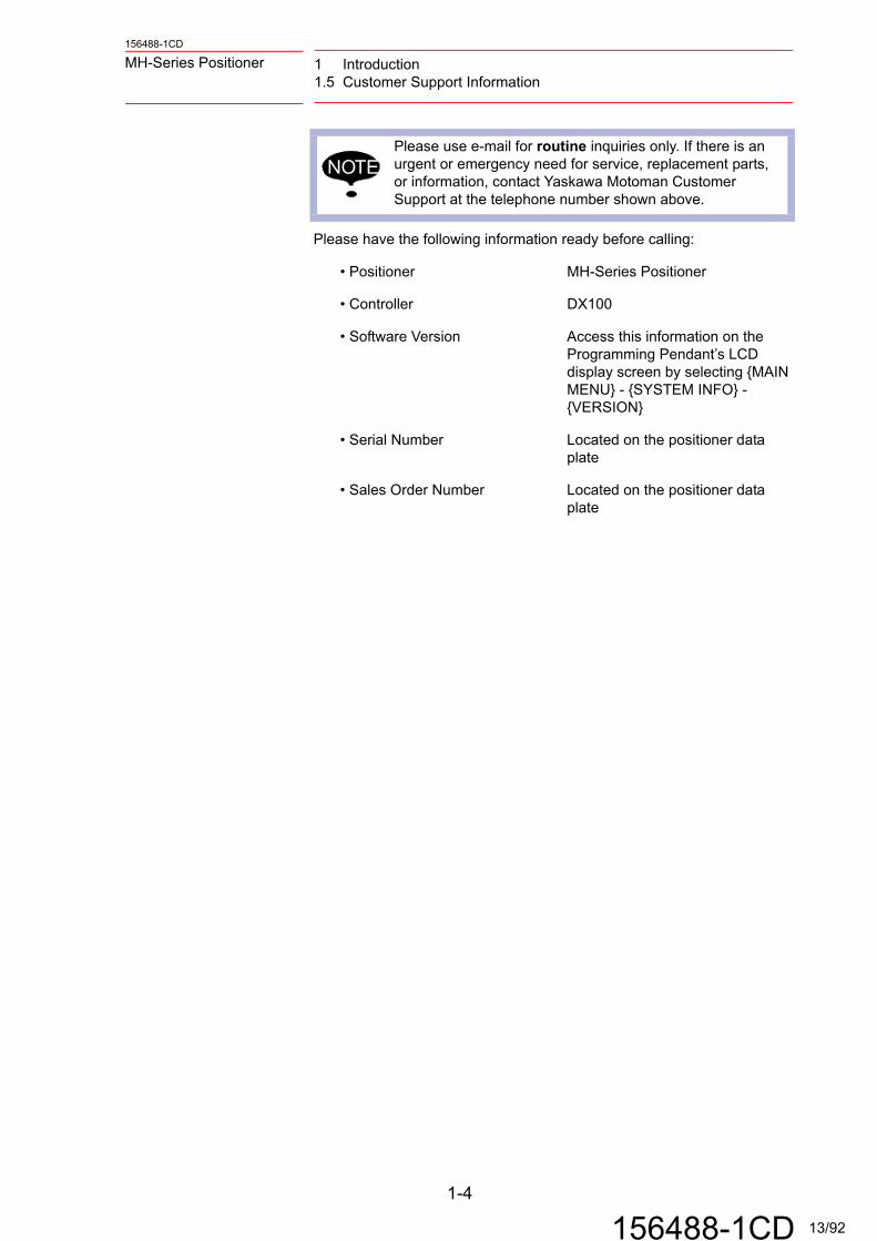
Please have the following information ready before calling:
NOTEPlease use e-mail for routine inquiries only. If there is an urgent or emergency need for service, replacement parts, or information, contact Yaskawa Motoman Customer Support at the telephone number shown above.
• Positioner MH-Series Positioner
• Controller DX100
• Software Version Access this information on the Programming Pendant’s LCD display screen by selecting {MAIN MENU} - {SYSTEM INFO} - {VERSION}
• Serial Number Located on the positioner data plate
• Sales Order Number Located on the positioner data plate
1-4
156488-1CD 13/92

2 Equipment Description2.1 General Information
156488-1CD
MH-Series Positioner
2 Equipment Description
2.1 General Information
The MH-Series SIGMA III Positioner Manual, Type I and Type II drive assemblies consist of an AC servo motoring gear reducer with an integral output bearing mounted in a cast iron housing.Weld ground brushes and position switches are included as standard features. Strive assembly provides programmable motion about the central axis, and endless rotation can be purchased as an option. Holes in the faceplate provide for mounting MotoMount drive components or parts fixtures in stand-alone (cantilevered) applications.
2.2 MH-Series SIGMA III Positioner Manual Drive Assembly –
Type I
The design of the four available drive assemblies is very similar; size is the primary difference. The flexibility of the Type I drive assembly allows for any mounting orientation including vertical (typical), horizontal, or other.The Type I drive assembly positioners (Fig. 2-3:) are available in four different models:
• MH90
• MH180
• MH500
• MH1600
Fig. 2-3: MH-Series SIGMA III Postioner Manual Drive Assembly - Type I
SERVOMOTOR,SIGMA III
CASTING
FACEPLATE,TOOLING
IN-POSITIONSWITCH,2-PLACES
HOMING PIN(ZERO ADJ)HOLE
2-1
156488-1CD 14/92

156488-1CD
MH-Series Positioner 2 Equipment Description2.2 MH-Series SIGMA III Positioner Manual Drive Assembly – Type I
2.2.1 MH-Series SIGMA III Positioner Manual, Type I – Specifications
See Fig. 2-3: for Type I, MH-Series SIGMA III Positioner Manual drive assembly specifications.
* External axis default settings
** The ‘In Position Maximum motion’ is the maximum motion expected if the cycle start command is given while the safety zone is violated. This assumes utilizing the position switches in the safety circuit, and includes the motion required to clear the switch actuators and implement and E-Stop.
Table 2-1: MH-Series SIGMA III Positioner Manual Type I Specifications
SERIES COMPONENT MH90 MH180 MH500 MH1600
Drive Assy PN 152543-1 152543-2 152547-1 152675-1
Axis Type* Rotation Rotation Rotation Rotation
Rated Load kgf 90 180 500 1600
Max MHT Load @ CG Off Center
kgf@mm 550@30 550@50 1075@80 3000@95
Headstock Speed rpm 24.7 12.4 9.8 10.8
180 Degree Sweep Timesec 1.72 2.74 3.56 3.28
Rated CG Off Center mm 152 152 152 152
Rated CG Overhang mm 500 137 100 50
Load @ 500 mm CG Overhang
kgf 75 75 175 500
Rated Inertia kg*m2 15 58 119 680
Rated Holding Torque Nm 153 275 829 2391
Rated Weld Current (Std/Optional)
Amps 400/800 400/800 800/1200 800/1600
Allowable Thrust kgf 400 400 800 2000
Motor Power Kw 0.55 0.55 1.3 3.7
Motor PN, YEC* SGMRS-06A2B-YR11
SGMRS-06A2B-YR11
SGMRS-13A2A-YR11
SGMRS-37A2A-YR11
Motor Speed* rpm 2000 2000 1500 2000
Rated Acceleration Time*
sec 0.3 0.3 0.3 0.5
Motor PN, Motoman 149568-4 149568-4 149568-6 149568-8
Reducer RV-20E-81-1B RV-20E-161-1B RV-80E-153-1B RV-320E-185
Total Reduction Ratio* R 81 161 153 185
Repeatability mm/mm 0.00003 0.00004 0.00003 TBD
E-Stop Response sec 0.5 0.5 0.5 TBD
E-Stop Response deg 34 17 13.5 TBD
In Position Maximum Motion**
deg TBD 19 15 TBD
Face Plate Through Holemm none none none none
Tail Stock Through Hole mm 38 38 41 45
Drive Assy Weight kgf/lbs 54/118 54/118 100/220 390/860
Standard Tooling Radius mm 815 815 815 1000
CAUTION
Operation outside the standard setup, without Yaskawa Motoman Engineering approval, is the operator's responsibility, may alter E-Stop performance, and may void the warranty.
2-2
156488-1CD 15/92

2 Equipment Description2.3 MH-Series SIGMA III Positioner Manual Drive Assembly – Type II
156488-1CD
MH-Series Positioner
2.3 MH-Series SIGMA III Positioner Manual Drive Assembly –
Type II
The appearance of the two available Type II drive assemblies is the same; capacity is the primary difference. The Type II drive assembly is designed for vertical mounting configurations.The Type II drive assembly positioners (see Fig. 2-4:) are available in two configurations:
• MH1200
• MH3100
Fig. 2-4: MH-Series SIGMA III Positioner Manual Drive — Type II
HOUSING
FACEPLATE
2-3
156488-1CD 16/92

156488-1CD
MH-Series Positioner 2 Equipment Description2.3 MH-Series SIGMA III Positioner Manual Drive Assembly – Type II
2.3.1 MH-Series SIGMA III Positioner Manual, Type II – Specifications
See Table 2-2: for Type II, MH-Series SIGMA III Positioner Manual drive assembly specifications.
* External axis default settings
** The ‘In Position Maximum motion’ is the maximum motion expected if the cycle start command is given while the safety zone is violated. This assumes utilizing the position switches in the safety circuit, and includes the motion required to clear the switch actuators and implement and E-Stop.
Table 2-2: MH-Series SIGMA iii, Type II Specifications
SERIES COMPONENT MH 3100 MH 1200
Drive Assy PN 152959-3 152959-4
Axis Type* Rotation Rotation
Rated Load kgf 3100 1200
Max MHT Load @ CG Off Center kgf@mm 6300@90 6300@30
Headstock Speed rpm 6.7 20.2
180 Degree Sweep Time sec 4.95 1.98
Rated CG Off Center mm 152 152
Rated CG Overhang mm 70 600
Load @ 500 mm CG Overhang kgf 1400 1400
Rated Inertia kg*m2 3058 300
Rated Holding Torque Nm 4622 1789
Rated Weld Current Amps 1200 1200
Allowable Thrust kgf 3000 3000
Motor Power Kw 4.4 4.4
Motor PN, YEC* SGMRS-44A2A-YR21 SGMRS-44A2A-YR21
Motor Speed* rpm 2000 2000
Rated Acceleration Time* sec 0.3 0.3
Motor PN, Motoman 149568-10 149568-10
Reducer RV-320C RV-320C
Total Reduction Ratio* R 11575/39 (296.795) 11575/117 (98.932)
Repeatability mm/mm 0.00004 0.00004
Repeatability w/Motomount mm/mm 0.000055 0.000055
E-Stop Response sec 0.55 0.55
E-Stop Response deg 12.5 37
In Position Maximum Motion** deg TBD TBD
Face Plate Through Hole mm 110 110
Tail Stock Through Hole mm 41 41
Drive Assy Weight kgf/lbs 918/2022 918/2022
Standard Tooling Radius mm 1000 1000
CAUTION
Operation outside the standard setup, without Yaskawa Motoman Engineering approval, is the operator's responsibility, may alter E-Stop performance, and may void the warranty.
2-4
156488-1CD 17/92

2 Equipment Description2.4 MotoMount™
156488-1CD
MH-Series Positioner
2.4 MotoMount™
MotoMount (see Figure 2-5) is a flexible tool fixture mounting system which improves tool repeat ability and reduces loads on the headstock/tailstock bearing systems. MotoMount accommodates combined headstock/tailstock/tooling misalignment up to two (2) degrees.
MotoMount is required for use with all Motoman MHT-series (headstock/tailstock) positioners. The MotoMount drive components are mounted onto the headstock faceplate, while the tailstock components replace earlier tailstock designs.
MotoMount is also available in a Heavy Duty (HD) configuration (see Figure 2-6).MotoMount HD is used on MH1200/1600/3100 drive assemblies. MH90/MH180/MH500 drive assemblies use the standard MotoMount.
CAUTION
Do not use MotoMount with stand-alone (no tailstock) applications. Use in a stand-alone application will result in uncontrollable tooling fixture motion.
2-5
156488-1CD 18/92

156488-1CD
MH-Series Positioner 2 Equipment Description2.4 MotoMount™
Fig. 2-5: MotoMount Layout
Fig. 2-6: MotoMount HD Layout
FACEPLATE
WELD GROUNDCABLE
TAILSTOCKTOOLINGADAPTER
DRIVEBUSHING
TAILSTOCKCOLUMN
FACEPLATE
WELD GROUNDCABLE
AUXILARYMOUNTINGHOLES
AUXILARYMOUNTINGHOLES
PRIMARYMOUNTINGHOLES
TAILSTOCKTOOLINGADAPTER
DRIVEBUSHING
BEARING
TAILSTOCKCOLUMN
LOCATING PIN
PRIMARYMOUNTINGHOLES
2-6
156488-1CD 19/92

3 Installation3.1 Materials Required
156488-1CD
MH-Series Positioner
3 Installation
3.1 Materials Required
This section identifies customer-supplied items and tools required to complete installation.
3.1.1 Customer-Supplied Items
• Servo motion control unit
• Incoming power supply
• Two earth ground cables with two earth ground stakes
3.1.2 List of Tools
CAUTION
• Installation of MotoMount and the MH-Series Positioner is not a task for the novice. These components are not fragile, but should still be handled with care. Rough handling can damage system electronic components.
• Installation of the MH-Series Positioner and MotoMount should be performed by personnel who are familiar with this Motoman product. Follow established safety procedures at all times throughout the installation process. Failure to use safe work practices can result in damage to the equipment and injury to the workers.
• Safety Glasses • Forklift and/or Overhead Crane
• Level • Open-end Wrench Set
• Adjustable Wrench Set • Wrench Set (Standard and Metric)
• Hammer Drill with Appropriate Concrete Bits
• Chalk String
3-1
156488-1CD 20/92

156488-1CD
MH-Series Positioner 3 Installation3.2 Installing the MH-Series SIGMA III Positioner Manual Drive – Type I
3.2 Installing the MH-Series SIGMA III Positioner Manual
Drive – Type I
3.2.1 Site Preparation
Each MH-Series SIGMA III Positioner Manual drive assembly should be firmly mounted on a machine base or foundation rigid enough to withstand the static and dynamic forces.
3.2.2 Unpacking
The headstock and optional tailstock are shipped on a wood shipping skid. To unpack the equipment, proceed as follows:
1. Carefully remove protective plastic wrapping from equipment.
2. Inspect equipment for shipping damage.
3. Unbolt equipment from wooden shipping skid (see Figure 3-7).
Fig. 3-7: Unbolting the Drive Assembly
WARNING
See the specification table for drive assembly weight. Make sure the lifing device is capable of handling this much weight or injury can occur.
NOTE Notify shipping contractor if there is any shipping damage.
SHIPPING SKID
SHIPPING BOLT
3-2
156488-1CD 21/92

3 Installation3.2 Installing the MH-Series SIGMA III Positioner Manual Drive – Type I
156488-1CD
MH-Series Positioner
4. Attach a capable lifting device to the eye bolts on top of the housing and lift the equipment from wooden shipping skid.
5. Place equipment in position using the layout prints.
3.2.3 Headstock Assembly Mounting Hole Pattern – MH90/180/500/1600
The headstock assembly may be mounted to the column assembly (see chapter 3.2.4.1 “Hole Patterns” ) or mounted to a customer-supplied machine base. For custom orientations, auxiliary mounting holes are provided on top of the drive assembly housing, and may be used in addition to the base mounting holes. Figure 3-8 shows the mounting hole pattern for the MH90/180. Figure 3-9 shows the mounting hole pattern for the MH500. Figure 3-10 shows the mounting hole pattern for the MH1600.Table 3-3 shows mounting specifications for Type I positioners.
Fig. 3-8: MH90/180 Mounting Hole Pattern
NOTE Make sure there is adequate room on all sides of the positioner for parts fixturing.
Table 3-3: Drive Assembly Mounting Specification - Type I
Drive Assembly Bolt Size,Grade 8.8 or Better
Tightening Torque(N•m/lbf-ft.)
MH90 M10 44/32
MH180 M10 44/32
MH500 M10 44/32
MH1600 M16 162/122
260.0 MM
4 X CLEARANCEFOR M10 SCREW
2 X M8 X 1.25AUXILARY MOUNTINGHOLES
105.0 MM
52.0 MM
140.0 MM60.0 MM
40.0 MM
2 X SF FOR M10 DOWEL
3-3
156488-1CD 22/92

156488-1CD
MH-Series Positioner 3 Installation3.2 Installing the MH-Series SIGMA III Positioner Manual Drive – Type I
Fig. 3-9: MH500 Mounting Hole Pattern
Fig. 3-10: MH1600 Mounting Hole Patter
350.0 MM
90.0 MM
190.0 MM 76.2 MM
135.0 MM
210.0 MM
2 X SF FORM12 DOWEL
56.9 MM
47.0 MM
190.0 MM
4 X CLEARANCEFOR M10 SCREW
2 X M10 X 1.5 THRUAUXILARY MOUNTING
HOLES
240.0 MM160.0 MM
6 X FOR CLEARANCEM16 SCREWS
2 x SF FOR M16DOWEL THRU
510.0 MM25.0 MM
207.0 MM
100.0 MM
300.0 MM
4 X M16 x 2.0 DIAM.AUXILARY MOUNTINGHOLES
73.0 MM
150.0 MM
75.0 MM
150.0 MM
3-4
156488-1CD 23/92

3 Installation3.2 Installing the MH-Series SIGMA III Positioner Manual Drive – Type I
156488-1CD
MH-Series Positioner
3.2.4 Column Assembly Mounting – Type I Drive Assembly
3.2.4.1 Hole Patterns
The column assembly for the MH-Series SIGMA III Positioner Manual positioner may be mounted to the floor or on a base. For accurate placement information, cross reference the hole pattern in with the specifications shown in Table 3-4:.
Fig. 3-11: Column-Mounting Hole Pattern - Type I
Table 3-4: Floor Anchoring Specifications - Type I
Drive Assembly Dynamic Rating per Anchor
A B C
MHT90/180/500 1360 kgf 300 250 M10
MHT1600 3400 kgf 700 420 M12
C – LAG BOLTCLEARENCE
A
B
NOTEDue to the variations in floor construction and preferences, this manual will not specify anchoring systems beyond dynamic rating requirements as listed in Table 3-4:.
3-5
156488-1CD 24/92

156488-1CD
MH-Series Positioner 3 Installation3.2 Installing the MH-Series SIGMA III Positioner Manual Drive – Type I
3.2.4.2 Installing the Type I Headstock Column Assembly
Refer to the system layout drawings to ensure precise set up location. To install the headstock, refer to figures above and proceed as follows:1. Set column assembly in desired position.
2. Use leveling bolt holes as a guide and transfer the hole locations to the concrete.
3. Remove column assembly.
4. Install the anchors per the manufacture’s instructions.
5. Install a leveling shim at each anchor location and reset the column assembly.
6. Screw each leveling bolt down until it just contacts the leveling shim and hand tighten the anchor bolts or nuts.
Fig. 3-12: Leveling Hardware
3.2.4.3 Leveling the Type I Headstock
The headstock must be leveled two directions: parallel to the faceplate and perpendicular to the faceplate. Since it only takes three points to define a plane, use only three of the four leveling bolts to level the system. It is important to consistently use the same three leveling bolts throughout each process. The fourth leveling bolt will be used as an anchor only.Before proceeding, make sure that the headstock is in the proper place. Make sure a leveling bolt, lock-nut, and leveling shim is installed in each column base hole.
To level the headstock assembly axially, proceed as follows:1. Place a level on top of the housing, perpendicular to the faceplate.
2. Use the two leveling bolts beneath the faceplate (A and B), and a third beneath the motor (C) to level axially 3.2.4.3 . If the faceplate side needs adjustment, A and B must be turned equally.
To level the headstock assembly cross-axially, proceed as follows:1. Place a level on top of the housing, parallel to the faceplate.
2. Use the same three leveling bolts used above and adjust them until the level is balanced, adjusting B + C equally.
3. Repeat the axial and cross-axial leveling steps until level readings are achieved both ways.
LEVELING SHIM
LEVELING BOLT
LOCK NUT
HEADSTOCKCOLUMN
FACEPLATE
COLUMN BASE
A
B
C
ANCHOR (CUSTOMER SUPPLIED)
3-6
156488-1CD 25/92

3 Installation3.2 Installing the MH-Series SIGMA III Positioner Manual Drive – Type I
156488-1CD
MH-Series Positioner
4. Drive the fourth leveling bolt down to the leveling shim.
5. Check level axial and cross-axial again. When level, tighten the anchor system (customer supplied) to the specified torque.
6. Tighten the four lock-nuts to the column base.
3.2.5 Connecting the Cables
Do not connect the encoder, power, and ground cables until after the drive
assembly is securely in place.
3.2.5.1 Connection to Motoman Controller
When the MH-Series SIGMA III Positioner Manual drive assembly is delivered with a Motoman robot, connections between the two usually have been made at the factory, or if not, instructions for making connections can be found in the system manual. See separate schematics and/or documentation specific to your system.
3.2.5.2 Ground Cables – Type I
Two locations are provided for attaching weld ground cables (see Fig. 3-13:). Use one for each welding power supply. Remove paint as required from the lug contact surface on the housing.
Fig. 3-13: Ground Cable Connections MH90/180/500/1600
3.2.6 Home Position
The MH-Series Positioner is set in HOME position at the factory. See chapter 5.5 “Reset Headstock To Home Position” , if adjustment is necessary.
NOTEWhen installing stand-along drive assemblies, user will need to mount the junction boxes close to the drive assembly for motor cables.
LUG BOLT
WELD GROUND
3-7
156488-1CD 26/92

156488-1CD
MH-Series Positioner 3 Installation3.3 Installing the MH-Series SIGMA III Positioner Manual Drive – Type II
3.3 Installing the MH-Series SIGMA III Positioner Manual
Drive – Type II
3.3.1 Site Preparation
Each MH-Series SIGMA III Positioner Manual drive assembly should be firmly mounted on a machine base or foundation rigid enough to withstand static and dynamic forces.
3.3.2 Unpacking
The headstock and optional tailstock are shipped on a wood shipping skid. To unpack the equipment, proceed as follows:
1. Carefully remove protective plastic wrapping from equipment.
2. Inspect equipment for shipping damage.
3. Unbolt headstock from wooden shipping skid (Figure 3-14) using a 3/4-inch socket.
4. Remove top cover and attach eye bolts to top of the housing and lift.
5. Place headstock in position.
WARNING
The MH-Series SIGMA III Positioner Manual headstock can weight as much as 1200 kg. Make sure the lifing device can handle this much weight or injury can result.
NOTE Notify shipping contractor if there is shipping damage.
NOTE Make sure there is adequate room on all sides of the positioner for parts fixturing.
3-8
156488-1CD 27/92
3 Installation3.3 Installing the MH-Series SIGMA III Positioner Manual Drive – Type II
156488-1CD
MH-Series Positioner
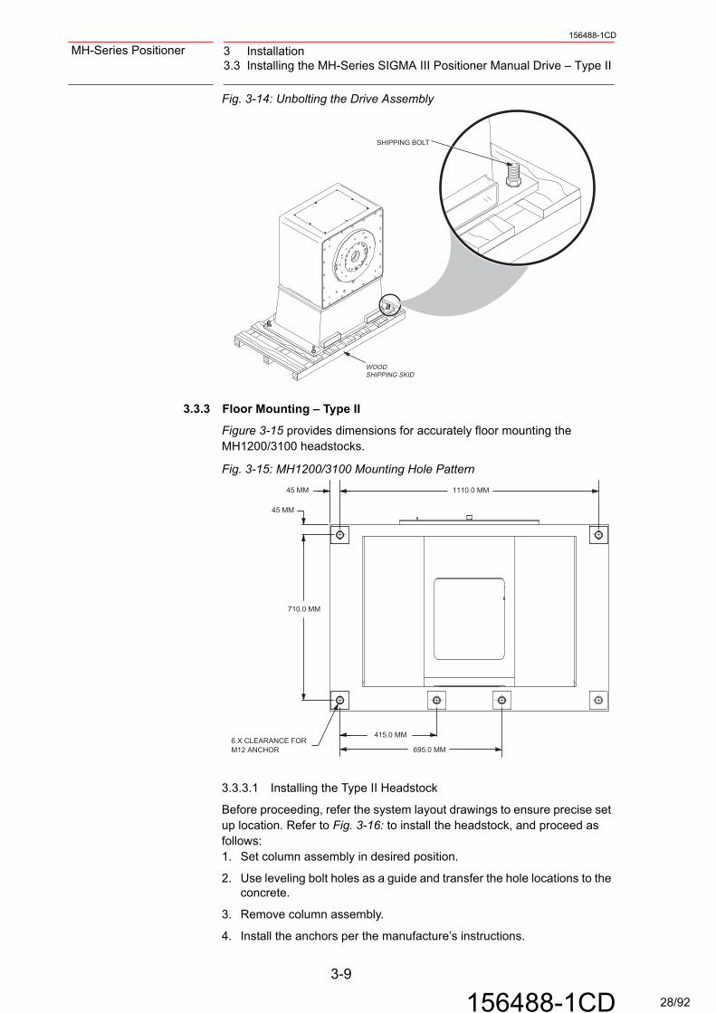
Fig. 3-14: Unbolting the Drive Assembly
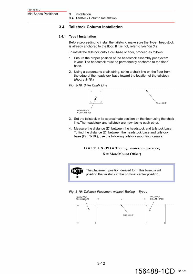
3.3.3 Floor Mounting – Type II
Figure 3-15 provides dimensions for accurately floor mounting the MH1200/3100 headstocks.
Fig. 3-15: MH1200/3100 Mounting Hole Pattern
3.3.3.1 Installing the Type II Headstock
Before proceeding, refer the system layout drawings to ensure precise set up location. Refer to Fig. 3-16: to install the headstock, and proceed as follows:1. Set column assembly in desired position.
2. Use leveling bolt holes as a guide and transfer the hole locations to the concrete.
3. Remove column assembly.
4. Install the anchors per the manufacture’s instructions.
WOODSHIPPING SKID
SHIPPING BOLT
1110.0 MM45 MM
415.0 MM
695.0 MM
45 MM
710.0 MM
6 X CLEARANCE FORM12 ANCHOR
3-9
156488-1CD 28/92

156488-1CD
MH-Series Positioner 3 Installation3.3 Installing the MH-Series SIGMA III Positioner Manual Drive – Type II
5. Install a leveling shim at each anchor location and reset the column assembly.
6. Screw each leveling bolt down until it just contacts the leveling shim and hand tighten the anchor bolts or nuts.
Fig. 3-16: Leveling Hardware
3.3.3.2 Leveling the Type II Headstock
The headstock must be leveled in two directions, parallel to the faceplate and perpendicular to the faceplate. Since it only takes three points to define a plane, use only three of the four leveling bolts to level the positioner. It is important to consistently use the same three leveling bolts throughout each process. The fourth leveling bolt will be used as an anchor only.Before proceeding, make sure that the headstock is in the proper place. Make sure a leveling bolt, lock-nut, and leveling shim is installed in each column base hole.
To level the headstock assembly axially, proceed as follows:1. Place a level on top of the housing, perpendicular to the faceplate.
2. Use the two leveling bolts beneath the faceplate (A and B), and a third beneath the motor (C) to level axially (3.2.4.3 ). If the faceplate side needs adjustment, A and B must be turned equally.
To level the headstock assembly cross-axially, proceed as follows:1. Place a level on top of the housing, parallel to the faceplate.
2. Use the same three leveling bolts used above and adjust them until the level is balanced, adjusting B + C equally.
3. Repeat the axial and cross-axial leveling steps until level readings are achieved in both directions.
4. Drive the remaining leveling bolts down to their leveling shims.
5. Check level axially and cross-axially again. When level, tighten the anchor system (customer-supplied) to the specified torque.
6. Tighten the six lock-nuts to the column base.
3.3.4 Connecting the Cables
Do not connect the encoder, power, and ground cables until after the drive assembly is securely in place.
LEVELING SHIM
ANCHOR (CUSTOMERSUPPLIED)
B
C
A
LEVELING BOLT
LOCK-NUT
HEADSTOCKRISER
FACEPLATE
COLUMN BASE
3-10
156488-1CD 29/92

3 Installation3.3 Installing the MH-Series SIGMA III Positioner Manual Drive – Type II
156488-1CD
MH-Series Positioner
3.3.5 Connection to Motoman Controller
When the MH-Series SIGMA III Positioner Manual drive assembly is delivered with a Motoman robot, connections between the two usually have been made at the factory, or if not, instructions for making connections can be found in the system manual. See separate schematics and/or documentation specific to your system.
3.3.5.1 Ground Cables – Type II
A ground cable bar is provided for attaching weld ground cables (fig. 3-17). Route the ground cables from the power source, up through the bottom of the Type II base, and attach to the ground cable bar.
Fig. 3-17: Ground Cable Connections MH1200/3100
3.3.6 Home Position
The MH-Series Positioner is set to the HOME position at the factory. See chapter 5.5 “Reset Headstock To Home Position” , if HOME position must be adjusted.
HEADSTOCK
DRIVE ASSEMBLY
LUG BOLT
WELD GROUND
3-11
156488-1CD 30/92
156488-1CD
MH-Series Positioner 3 Installation3.4 Tailstock Column Installation
3.4 Tailstock Column Installation
3.4.1 Type I Installation
Before proceeding to install the tailstock, make sure the Type I headstock is already anchored to the floor. If it is not, refer to Section 3.2.
To install the tailstock onto a cell base or floor, proceed as follows:
1. Ensure the proper position of the headstock assembly per system layout. The headstock must be permanently anchored to the floor/base.
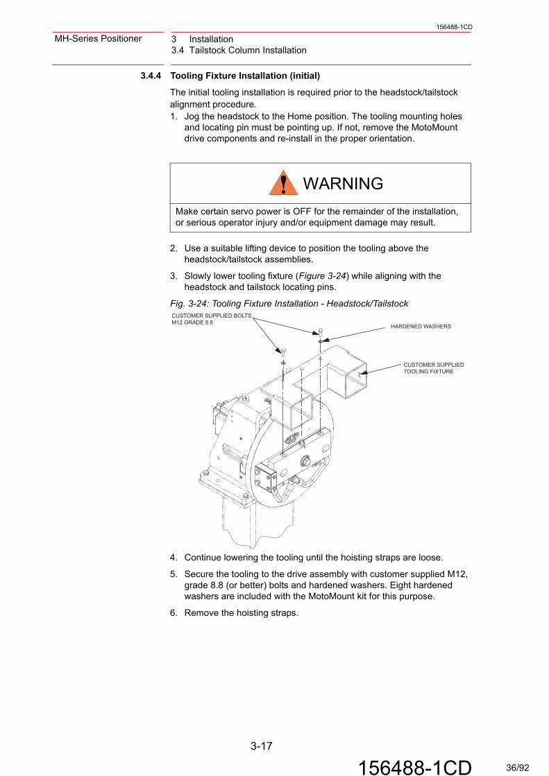
2. Using a carpenter’s chalk string, strike a chalk line on the floor from the edge of the headstock base toward the location of the tailstock (Figure 3-18.)
Fig. 3-18: Srike Chalk Line
3. Set the tailstock in its approximate position on the floor using the chalk line.The headstock and tailstock are now facing each other.
4. Measure the distance (D) between the headstock and tailstock base. To find the distance (D) between the headstock base and tailstock base (Fig. 3-19:), use the following tailstock mounting formula:
D = PD + X (PD = Tooling pin-to-pin distance;
X = MotoMount Offset)
Fig. 3-19: Tailstock Placement without Tooling – Type I
NOTE The placement position derived form this formula will position the tailstock in the nominal center position.
CHALKLINE
HEADSTOCKCOLUMN BASE
HEADSTOCKCOLUMN BASE
TAILSTOCKCOLUMN BASED
CHALKLINE
3-12
156488-1CD 31/92

3 Installation3.4 Tailstock Column Installation
156488-1CD
MH-Series Positioner
5. To find the X value in the tailstock mounting formula for your drive assembly, locate the drive assembly model name in Table 3-5
3.4.2 Type II Installation
To install the tailstock of a Type II assembly onto a cell base or floor, proceed as follows:1. Ensure the proper position the headstock assembly per system layout.
The headstock must be permanently anchored to the floor/base.
2. Using a carpenter’s chalk string, strike a chalk line on the floor from the edge of the headstock base towards location of the tailstock (Figure 3-18).
3. Position the tailstock on the floor across from the headstock (Figure 3-18). Use the chalk line and the center line of each component as guides for placement of the tailstock column on the floor.
4. To position the tailstock accurately on the bearing center line, make two measurements from the tailstock base to the chalk line and adjust the base as necessary (Figure 3-20).
Fig. 3-20: Tailstock Placement - Type II
Table 3-5: Column Installation - X value
Type I System X - value
MHT90/180 - mm -38
MHT340 - mm 61
MHT500 - mm 57
MHT1600 - mm 156
MHT1200/3100 - mm 138
NOTE
Keeping the center line of each component aligned is not critical. However, the closer the bearings of both components are aligned with one another, the greater the degree of misalignment allowed with other system components
HEADSTOCKRISER BASE
CHALK LINE 225 MM(8.85 IN.)
TAILSTOCKRISER BASE
D
HEADSTOCK/TAILSTOCKBEARING CENTERLINE
3-13
156488-1CD 32/92

156488-1CD
MH-Series Positioner 3 Installation3.4 Tailstock Column Installation
3.4.3 Leveling the Tailstock
3.4.3.1 Type I Leveling Procedures
The tailstock must be leveled in two directions, axially and cross-axially. Since it only takes three points to define a plane, use only three of the four leveling bolts to level the system. It is important to consistently use the same three leveling bolts throughout each process. The fourth leveling bolt will be used as an anchor only.Before proceeding, make sure that the tailstock is in the proper place. Make sure a leveling bolt, lock-nut, and leveling shim is installed in each column base hole.
Fig. 3-21: Leveling the Tailstock Type I
To level the tailstock assembly axially, proceed as follows:1. Place a level on top of the tailstock column in the axial direction.
2. Use the leveling bolts A, B, and C to adjust the axial level. Adjust bolts A + B equally.
To level the tailstock assembly cross-axially, proceed as follows:1. Place a level on top of the tailstock in the cross-axial direction.
2. Use the same three leveling bolts used above and adjust them until the level is balanced, adjusting B + C equally.
3. Repeat the axial and cross-axial leveling steps until level readings are achieved both ways
4. Drive the fourth leveling bolt down to the leveling shim.
5. Check level axially and cross-axially again. When level, tighten the anchoring system (customer-supplied) to the specified torque.
6. Tighten the four lock-nuts to the column base.
AXIAL
CROSS-AXIAL
DRIVE ASSEMBLY
AB
C
LEVELING SHIM
ANCHOR (CUSTOMERSUPPLIED)
LEVELING BOLT
LOCK-NUT
HEADSTOCKRISER
COLUMN BASE
3-14
156488-1CD 33/92

3 Installation3.4 Tailstock Column Installation
156488-1CD
MH-Series Positioner
3.4.3.2 Type II Leveling Procedures
The Type II tailstock must be leveled in two directions, axially and cross-axially. Since it only takes three points to define a plane, use only three of the four leveling bolts to level the system. It is important to consistently use the same three leveling bolts through out each process. The fourth leveling bolt will be used as an anchor only.
Before proceeding, make sure that the tailstock is in the proper place. Make sure a leveling bolt, lock-nut, and leveling shim is installed in each column base hole.
Fig. 3-22: Leveling the Tailstock - Type II
To level the tailstock assembly axially, proceed as follows:1. Place a level on top of the tailstock column in the axial direction.
2. Use the leveling bolts A, B, and C to adjust the axial level. Adjust bolts A + B equally.
To level the tailstock assembly cross-axially, proceed as follows:1. Place a level on top of the tailstock in the cross-axial direction.
2. Use the same three leveling bolts used above and adjust them until the level is balanced, adjusting B + C equally.
3. Repeat the axial and cross-axial leveling steps until level readings are achieved both directions.
4. Drive the fourth leveling bolt down to the leveling shim.
5. Check level axially and cross-axially again. When level, tighten the anchoring system (customer supplied) to the specified torque.
6. Tighten the four lock-nuts to the column base.
B
C
AXIAL
CROSS-AXIAL
A
LEVELING SHIM
ANCHOR (CUSTOMERSUPPLIED)
LEVELING BOLT
LOCK-NUT
HEADSTOCKRISER
COLUMN BASE
3-15
156488-1CD 34/92

156488-1CD
MH-Series Positioner 3 Installation3.4 Tailstock Column Installation
3.4.3.3 Allowable Misalignment
The flexibility of MotoMount HD allows for a misalignment between the tailstock and the tooling fixture without affecting performance (Figure 3-23). A misalignment of 0.5 degrees is allowed. If the tailstock is out of alignment more than 0.5 degrees, adjust the tailstock using the tailstock leveling bolts.
Fig. 3-23: Allowable Axial Leveling - Side ViewLEVELINGDEVICE0 – 0.5 DEGREE MAX.
3-16
156488-1CD 35/92
3 Installation3.4 Tailstock Column Installation
156488-1CD
MH-Series Positioner
3.4.4 Tooling Fixture Installation (initial)
The initial tooling installation is required prior to the headstock/tailstock alignment procedure.1. Jog the headstock to the Home position. The tooling mounting holes
and locating pin must be pointing up. If not, remove the MotoMount drive components and re-install in the proper orientation.
2. Use a suitable lifting device to position the tooling above the headstock/tailstock assemblies.
3. Slowly lower tooling fixture (Figure 3-24) while aligning with the headstock and tailstock locating pins.
Fig. 3-24: Tooling Fixture Installation - Headstock/Tailstock
4. Continue lowering the tooling until the hoisting straps are loose.
5. Secure the tooling to the drive assembly with customer supplied M12, grade 8.8 (or better) bolts and hardened washers. Eight hardened washers are included with the MotoMount kit for this purpose.
6. Remove the hoisting straps.
WARNING
Make certain servo power is OFF for the remainder of the installation, or serious operator injury and/or equipment damage may result.
CUSTOMER SUPPLIEDTOOLING FIXTURE
HARDENED WASHERS
CUSTOMER SUPPLIED BOLTSM12 GRADE 8.8
3-17
156488-1CD 36/92

156488-1CD
MH-Series Positioner 3 Installation3.4 Tailstock Column Installation
3.4.5 Tooling Fixture Installation (regular)
1. Jog the headstock until MotoMount is horizontal. The tooling mounting holes and locating pin must be pointing up.
2. Use a suitable lifting device to position the tooling above the headstock assembly Figure 3-24.
3. Slowly lower one side of the tooling fixture onto the headstock using the locating pin.
4. Install the M12 tool mounting bolts and washers onto the headstock (customer-supplied grade 8.8 bolts), and torque the bolts to 76 N•m (56 lbf-ft).
3.4.6 Final Alignment Check
The MotoMount system helps reduce the load on bearings due to tooling fixture misalignment with the headstock and tailstock. However, optimum performance is achieved when the alignment is as close as possible. Horizontal and vertical misalignment is possible. Both the horizontal and vertical alignment procedures require the measurement of the same gap on the MotoMount drive components. A tooling fixture must be installed to align the system.
3.4.6.1 Horizontal Alignment
Check the horizontal alignment by measuring the gap (see Figure 3-25) between the mounting fixture and mounting block. The measurement of this gap must not change more than 1 mm after the headstock is rotated 180 degrees. To check MotoMount’s horizontal alignment, proceed as follows:1. Jog the positioner until MotoMount is horizontal.
2. Using calipers, measure the alignment gap.
3. Rotate the positioner 180 degrees.
WARNING
Make certain servo power is OFF for the remainder of the installation, or serious operator injury and/or equipment damage may result.
NOTE The alignment procdure may be easier if the weld ground cable is removed.
NOTE It is important to measure the alignment gap at the same location. This will ensure proper alignment.
3-18
156488-1CD 37/92

3 Installation3.4 Tailstock Column Installation
156488-1CD
MH-Series Positioner
4. Measure the alignment gap at the second position. If the gaps differ by more than 1 mm, the horizontal alignment must be adjusted. Use the following procedure to adjust horizontal alignment:
• Calculate the average gap between the two positions, by adding both measurements together and dividing by two.
• Loosen the bearing mounting bolts and move the tailstock bearing housing towards the direction of the larger gap until the gap is at the average value.
• Ensure the bearing housing is perpendicular to the tailstock adapter within 1/2 degree (a visual check with a square is acceptable).
• Repeat this process until the gap at both positions is within 1 mm. If moving the bearing housing cannot provide the desired results, the columns are out of basic alignment and must be repositioned.
• Tighten the bearing mounting bolts to 76 N • m (56 lbf-ft).
Fig. 3-25: Measurement Point for Horizontal Alignment, Bottom ViewHEADSTOCK FACEPLATE
ALIGNMENT GAP
MOUNTING BLOCK
DRIVE BUSHING
FIXTURE BLOCK
3-19
156488-1CD 38/92
156488-1CD
MH-Series Positioner 3 Installation3.4 Tailstock Column Installation
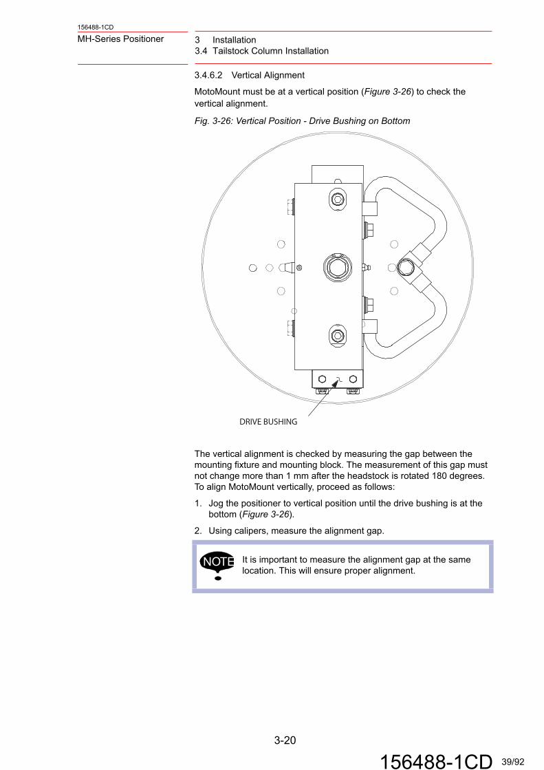
3.4.6.2 Vertical Alignment
MotoMount must be at a vertical position (Figure 3-26) to check the vertical alignment.
Fig. 3-26: Vertical Position - Drive Bushing on Bottom
The vertical alignment is checked by measuring the gap between the mounting fixture and mounting block. The measurement of this gap must not change more than 1 mm after the headstock is rotated 180 degrees. To align MotoMount vertically, proceed as follows:
1. Jog the positioner to vertical position until the drive bushing is at the bottom (Figure 3-26).
2. Using calipers, measure the alignment gap.
NOTE It is important to measure the alignment gap at the same location. This will ensure proper alignment.
DRIVE BUSHING
3-20
156488-1CD 39/92
3 Installation3.4 Tailstock Column Installation
156488-1CD
MH-Series Positioner
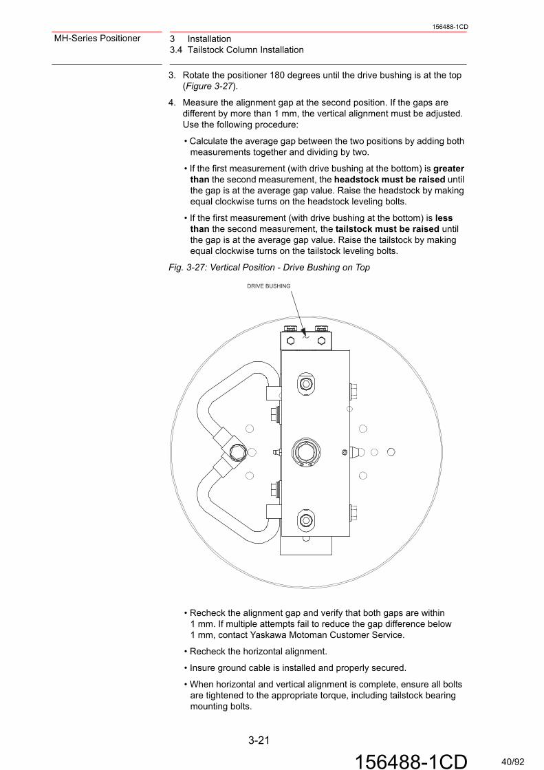
3. Rotate the positioner 180 degrees until the drive bushing is at the top (Figure 3-27).
4. Measure the alignment gap at the second position. If the gaps are different by more than 1 mm, the vertical alignment must be adjusted. Use the following procedure:
• Calculate the average gap between the two positions by adding both measurements together and dividing by two.
• If the first measurement (with drive bushing at the bottom) is greater than the second measurement, the headstock must be raised until the gap is at the average gap value. Raise the headstock by making equal clockwise turns on the headstock leveling bolts.
• If the first measurement (with drive bushing at the bottom) is less than the second measurement, the tailstock must be raised until the gap is at the average gap value. Raise the tailstock by making equal clockwise turns on the tailstock leveling bolts.
Fig. 3-27: Vertical Position - Drive Bushing on Top
• Recheck the alignment gap and verify that both gaps are within 1 mm. If multiple attempts fail to reduce the gap difference below 1 mm, contact Yaskawa Motoman Customer Service.
• Recheck the horizontal alignment.
• Insure ground cable is installed and properly secured.
• When horizontal and vertical alignment is complete, ensure all bolts are tightened to the appropriate torque, including tailstock bearing mounting bolts.
DRIVE BUSHING
3-21
156488-1CD 40/92

156488-1CD
MH-Series Positioner 3 Installation3.5 MotoMount Installation
3.4.7 Tooling Fixture Removal
1. Jog the headstock until the MotoMount is horizontal, with the tool mounting bolts and locating pin pointed up.
2. Position a suitable lifting device and hoisting straps above the tooling. Attach the hoisting straps to the tooling fixture.
3. Remove the tool fixture mounting bolts and tailstock bearing cap.
4. Slowly lift the tooling fixture off the headstock/tailstock assemblies.
3.5 MotoMount Installation
The MotoMount drive components are usually delivered assembled to the drive assembly (MH90, MH180, or MH500). However, if you are retrofitting MotoMount on a system already installed in your plant, follow these instructions:
3.5.1 Preparation
Successful installation requires the MotoMount drive components be firmly mounted to the headstock faceplate. Before installation, ensure the faceplate is clean and is not warped or deformed.
3.5.2 Unpack and Assemble
The MotoMount system will be shipped in a box with the following components (unless it is part of a larger system):
• MotoMount drive components
• Dowel pins (2)
• Mounting hardware
• Weld ground cable
Carefully remove plastic wrapping from components and inspect them for shipping damage.
WARNING
Make certain servo power is OFF for the remainder of the installation, or serious operator injury and/or equipment damage may result.
NOTE Notify your shipping contractor if you notice any shipping damage.
3-22
156488-1CD 41/92

3 Installation3.5 MotoMount Installation
156488-1CD
MH-Series Positioner
3.5.2.1 Installing Fixture Dowel Pins
The dowel pins must be installed into the back of the mounting block before the assembly is mounted onto the faceplate. There are four holes in the back of the mounting block. See Figure 3-28 to determine which holes to use for your application. If your headstock faceplate does not have the matching dowel holes, it must be modified per the following template (Figure 3-28).
Fig. 3-28: MotoMount Mounting Hole Pattern
To install the dowel pins, proceed as follows
:
1. Use a small, 3-mm thick metal spacer (a 1/8-in. thick washer will work) to transfer the press force from the mounting block to the fixture block.
2. Place the spacer between the mounting block and the fixture block so that it is located behind the appropriate dowel hole.
3. Use an arbor press to force the dowel pins into the appropriate dowel pin hole in the mounting block. It is important that the dowel pin is pressed in as far as possible.
4. Relocate the spacer behind the other dowel hole and install the second dowel pin.
5. After the dowel pins are inserted properly, remove the spacer.
The MotoMount drive components are now ready to install onto the faceplate.
WARNING
Be sure to handle the MotoMount components carefully to avoid damage to the equipment or injury to personnel.
M12 X 1.75MH75/150 DOWEL
POSITION
250.00 MM +/- 0.015
125 MM
CENTER OFROTATION DIA. 12.00 THRU
FOR DOWEL
MH340/450/680DOWEL POSITION
200 MM
80 MM
100.0 MM
160.00 MM +/- 0.015
3-23
156488-1CD 42/92
156488-1CD
MH-Series Positioner 3 Installation3.5 MotoMount Installation
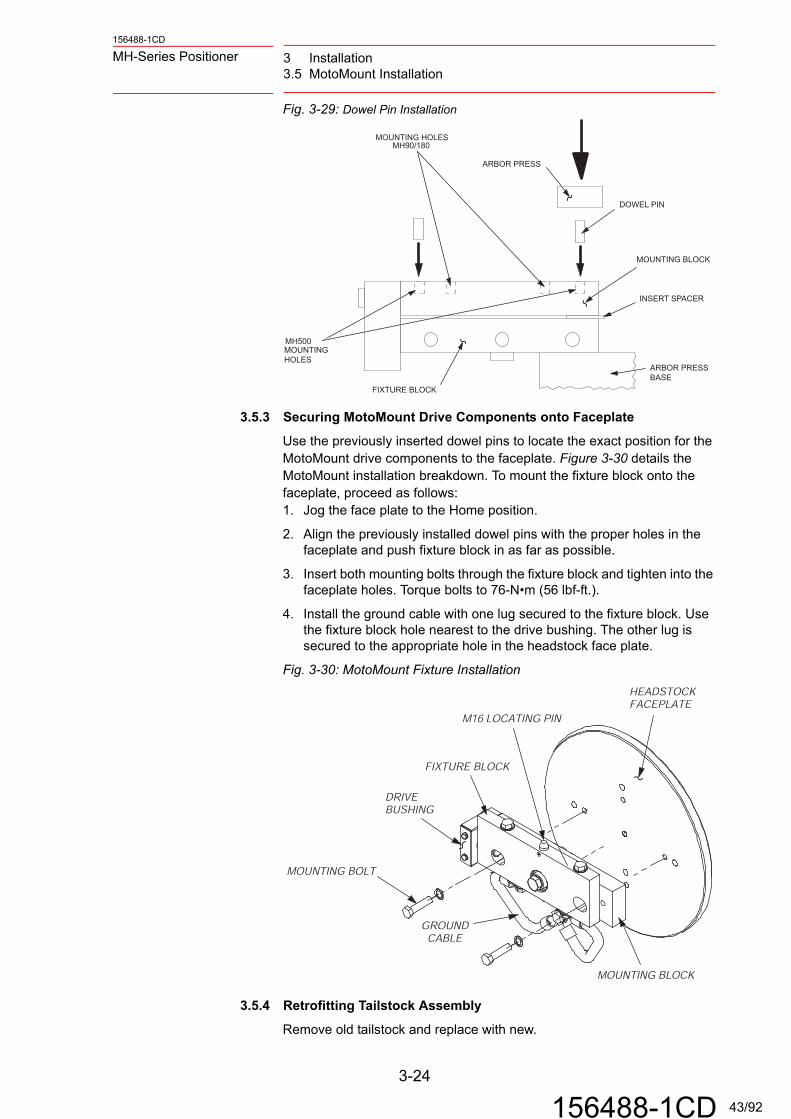
Fig. 3-29: Dowel Pin Installation
3.5.3 Securing MotoMount Drive Components onto Faceplate
Use the previously inserted dowel pins to locate the exact position for the MotoMount drive components to the faceplate. Figure 3-30 details the MotoMount installation breakdown. To mount the fixture block onto the faceplate, proceed as follows:1. Jog the face plate to the Home position.
2. Align the previously installed dowel pins with the proper holes in the faceplate and push fixture block in as far as possible.
3. Insert both mounting bolts through the fixture block and tighten into the faceplate holes. Torque bolts to 76-N•m (56 lbf-ft.).
4. Install the ground cable with one lug secured to the fixture block. Use the fixture block hole nearest to the drive bushing. The other lug is secured to the appropriate hole in the headstock face plate.
Fig. 3-30: MotoMount Fixture Installation
3.5.4 Retrofitting Tailstock Assembly
Remove old tailstock and replace with new.
MH500MOUNTINGHOLES
ARBOR PRESS
DOWEL PIN
MH90/180MOUNTING HOLES
INSERT SPACER
FIXTURE BLOCK
MOUNTING BLOCK
ARBOR PRESSBASE
MOUNTING BLOCK
MOUNTING BOLT
GROUNDCABLE
HEADSTOCKFACEPLATE
FIXTURE BLOCK
M16 LOCATING PIN
DRIVEBUSHING
3-24
156488-1CD 43/92

3 Installation3.6 MotoMount HD Adjustments
156488-1CD
MH-Series Positioner
3.6 MotoMount HD Adjustments
MotoMount HD is used on the MH1600 (Type I), MH1200 (Type II), and MH3100 (Type II) drive assemblies.The MotoMount components are delivered assembled to the headstock and tailstock assemblies. See Section 3.4 for installation of the headstock and tailstock assemblies.
Fig. 3-31: Nominal Center Position - Side View
3.6.1 Allowable Misalignment
The flexibility of MotoMount allows for misalignment between the tailstock and the tooling fixture without affecting performance. A total misalignment (combined tooling and headstock/tailstock) up to two degrees, from top view is permissible (Figure 3-32). If misalignment exceeds two degrees, check tooling and/or position of tailstock.
Fig. 3-32: Allowable Misalignment - Top View
22 MM
29 MM
TAILSTOCKCOLUMNTOP
ADAPTERCLAMP
ADAPTERSHAFT
TAILSTOCKADAPTER
TAILSTOCKCOLUMN
TOOLINGFIXTURE
TAILSTOCKADAPTER
TOOLINGFIXTURE
2 DEGREES
3-25
156488-1CD 44/92

156488-1CD
MH-Series Positioner 3 Installation3.6 MotoMount HD Adjustments
3.6.2 Tooling Fixture Installation – MotoMount HD
Both the headstock and tailstock must be permanently anchored to the floor and leveled prior to installation of the tooling fixture.1. Jog the headstock until MotoMount HD is horizontal. The tooling
mounting holes and locating pin must be pointing up.
2. Use a suitable lifting device to position the tooling above the headstock assembly (4.).
3. Slowly lower one side of the tooling fixture onto the headstock using the locating pin.
4. Install the M16 tool mounting bolts and washers onto the headstock (customer-supplied grade 8.8 bolts), and torque the bolts to 190 N•m (140 lbf-ft). Hardened washers are recommended.
5. Slowly lower tooling fixture onto the tailstock using the locating pin.
6. Install the M16 tool mounting bolts and washers onto the tailstock (customer-supplied grade 8.8 bolts), and torque the bolts to 190 N•m (140 lbf-ft). Hardened washers are recommended.
7. Remove the hoisting straps.
3.6.3 Tooling Fixture Removal
1. Jog the headstock until the MotoMount is horizontal, with the tool mounting bolts and locating pin pointed up.
2. Position a suitable lifting device and hoisting straps above the tooling. Attach the hoisting straps to the tooling fixture.
3. Remove the tool fixture mounting bolts and tailstock bearing cap.
4. Slowly lift the tooling fixture off the headstock/tailstock assemblies.
3.6.4 Variable Tooling Size Accommodations
The MotoMount system can adapt to small variations in tooling fixture lengths without changing the tailstock’s performance or permanent location. Two steps can be taken to adjust the tooling fixture distance.
WARNING
Make certain servo power is OFF for the remainder of the installation, or serious operator injury and/or equipment damage may result
WARNING
The servo motor must be off for the remainder of the removal, or serious operator injury and/or equipment damage may result.
3-26
156488-1CD 45/92

3 Installation3.7 Conducting a Safety/Operation Check
156488-1CD
MH-Series Positioner
3.6.4.1 Changing Adapter Shaft Position
The preferred way change the adapter shaft position is to simply slide the tailstock adapter either way along the adapter shaft. If more adjustment is needed, loosen the four tailstock bolts and slide the adapter shaft and the tailstock adapter until a suitable position is acquired. These two processes do not effect MotoMount’s performance. It is important that a minimum distance is maintained between the tailstock adapter and the top of the tailstock column (Figure 3-33).
Fig. 3-33: Changing Adapter Shaft Position
3.6.4.2 Reinstalling the Adapter Shaft
Once the new position for the adapter shaft is found, torque the tailstock bolts to 350 N•m (259 lbf-ft.).
3.7 Conducting a Safety/Operation Check
Before operating either MH-Series SIGMA III Positioner Manual system, take a few minutes to perform a safety/operation check. To perform a safety/operation check, proceed as follows:1. Check that all cable connections are tight.
2. Verify the headstock and tailstock are level and parallel.
12.7 MM MINIMUM DISTANCE
ADAPTERSHAFT
TAILSTOCKADAPTOR
TAILSTOCKBOLT
TAILSTOCKCOLUMNTOP
3-27
156488-1CD 46/92

156488-1CD
MH-Series Positioner 4 Tooling Recommendations4.1 Headstock Only – Tooling Recommendations
4 Tooling Recommendations
Installation of tooling and fixtures should be performed by personnel who are familiar with the operation of this system. Tooling and fixtures are supplied by the customer.There are two system configurations possible with the MH-Series Positioner headstock only and headstock/tailstock with MotoMount. To ensure optimal performance from your MH-Series Positioner tooling system, Yaskawa makes the following recommendations for each configuration.
4.1 Headstock Only – Tooling Recommendations
The stand-alone headstock assembly provides the only support for tooling and production parts. Proper tooling design directly effects the headstock performance and longevity. All tooling practices apply to the headstock assembly whether it is accompanied by a column or not.
Fig. 4-34: Headstock Assembly - Type I
Fig. 4-35: Headstock Assembly - Type II
HOUSING
COLUMN
FACEPLATEAC SERVOMOTOR
FACEPLATE
HOUSING
4-1
156488-1CD 47/92

4 Tooling Recommendations4.1 Headstock Only – Tooling Recommendations
156488-1CD
MH-Series Positioner
4.1.1 Customer-supplied Tooling Fixture
The customer-supplied tooling hangs from the faceplate as it supports production parts for welding. Customers control/change the design of tooling fixtures to match the design of the production parts.
4.1.1.1 Recommendations
To ensure optimum performance from the customer-supplied tooling fixture, please read the following recommendations:
• Use all bolt holes on the faceplate to mount the tooling fixture.
• Use the dowel pins.
4.1.1.2 Mounting Holes – Faceplate
The customer-supplied tooling must be designed to fit the MH-Series Positioner faceplate mounting holes. See Fig. 4-37: for MH90/180 faceplate mounting hole pattern. See Fig. 4-37: for MH500 faceplate mounting hole pattern. See Fig. 4-39: for MH1600 faceplate mounting hole pattern. See fig. 4-36 for MH1200/3100 faceplate mounting hole pattern.
Fig. 4-36: Mounting Holes on Faceplate MH90/180
100.0 MM
80.0 MM 80.0 MM
100.0 MM
100.0 MM 100.0 MM
4 X 12 X 1.75
18 MM DEEP
2 X SLIP FIT FOR
M12 DOWEL
320.0 MM
4-2
156488-1CD 48/92
156488-1CD
MH-Series Positioner 4 Tooling Recommendations4.1 Headstock Only – Tooling Recommendations
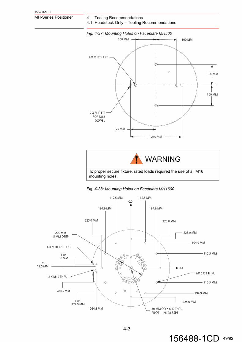
Fig. 4-37: Mounting Holes on Faceplate MH500
Fig. 4-38: Mounting Holes on Faceplate MH1600
WARNING
To proper secure fixture, rated loads required the use of all M16 mounting holes.
100 MM 100 MM
250 MM
125 MM
2 X SLIP FITFOR M12
DOWEL
4 X M12 x 1.75
100 MM
100 MM
0.0
30 MM OD X 6 ID THRUPILOT – 1/8-28 BSPT
M16 X 2 THRU
225.0 MM
274.5 MM
30 MMTYP.
TYP.12.5 MM
4 X M10 1.5 THRU
2 X M12 THRU
225.0 MM
194.9 MM 194.9 MM
112.5 MM 112.5 MM0.0
225.0 MM
194.9 MM
112.5 MM
225.0 MM
194.9 MM
112.5 MM
5 MM DEEP200 MM
284.5 MM
264.5 MM
TYP.
4-3
156488-1CD 49/92

4 Tooling Recommendations4.2 Headstock/Tailstock with MotoMount
156488-1CD
MH-Series Positioner
Fig. 4-39: Mounting Holes on Faceplate MH1200/3100
4.2 Headstock/Tailstock with MotoMount
4.2.1 Customer-supplied Tooling Fixtures
With MotoMount, the customer-supplied tooling fixture bridges the headstock and tailstock together as it supports production parts for welding. Customer design their tooling fixtures to fit their specific needs. Modifications to existing tooling fixtures will be minimal as long it fits the current headstock/tailstock configuration (retrofit application)
4.2.2 Multiple Tooling Fixtures
Some applications require multiple tooling fixtures that are switched in and out of the positioner as production needs change. To prepare these extra fixtures to work with MotoMount, the following spare parts are needed:
• Bearing adapter
• Bearing
Contact Yaskawa Motoman Customer Service at (937) 847- 3200, to purchase these parts.
0.0
0.0
DIA. 120 THRU
M16 X 2 THRU
225.0 MM
274.5 MM
30 MMTYP.
TYP.12.5 MM
4 X M10 1.5 THRU
2 X M12 THRU
225.0 MM
194.9 MM 194.9 MM
112.5 MM 112.5 MM
225.0 MM
194.9 MM
112.5 MM
225.0 MM
194.9 MM
112.5 MM
5 MM DEEP200 MM
284.5 MM
264.5 MM
TYP.
4-4
156488-1CD 50/92
156488-1CD
MH-Series Positioner 4 Tooling Recommendations4.2 Headstock/Tailstock with MotoMount
4.2.3 Specifications
To ensure that the customer-supplied tooling fixture fits properly to MotoMount, the following specifications must be met.
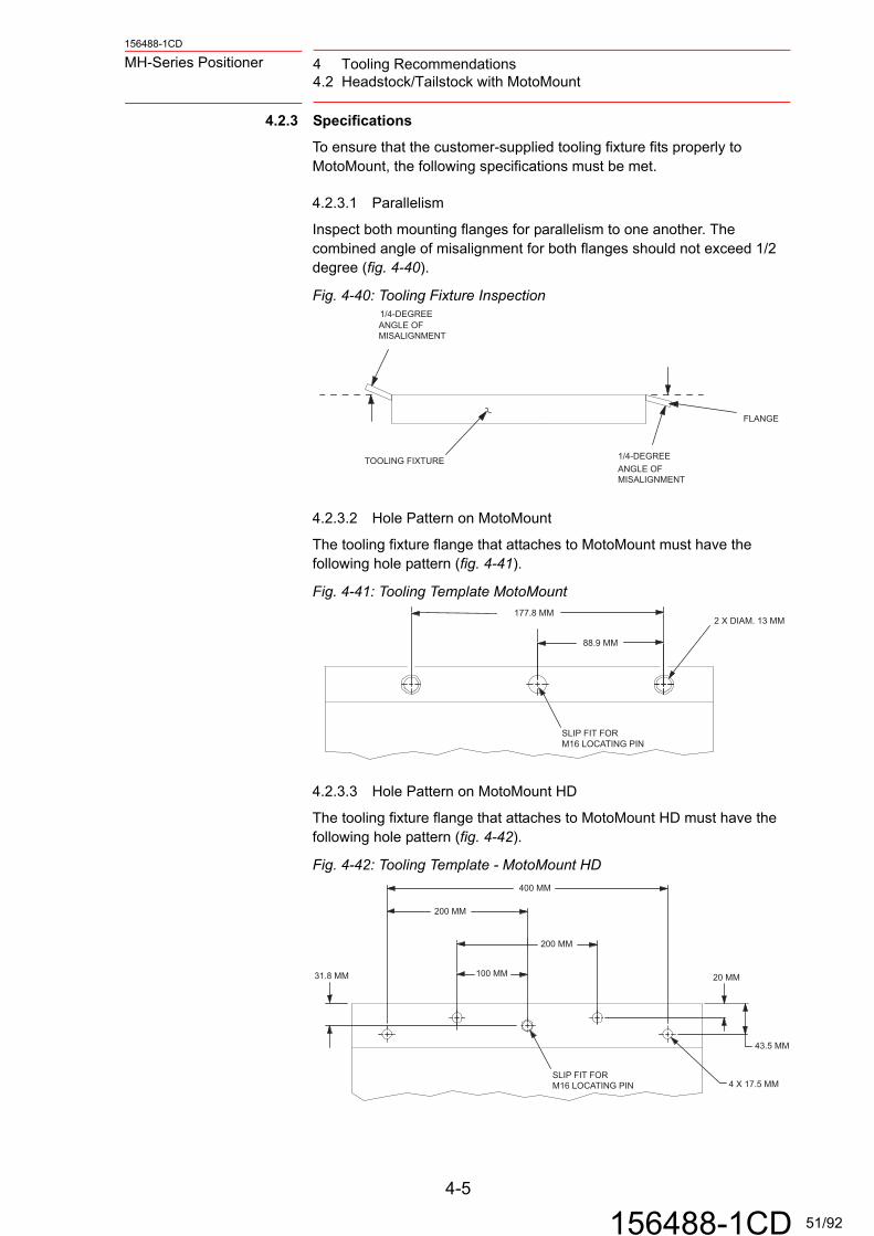
4.2.3.1 Parallelism
Inspect both mounting flanges for parallelism to one another. The combined angle of misalignment for both flanges should not exceed 1/2 degree (fig. 4-40).
Fig. 4-40: Tooling Fixture Inspection
4.2.3.2 Hole Pattern on MotoMount
The tooling fixture flange that attaches to MotoMount must have the following hole pattern (fig. 4-41).
Fig. 4-41: Tooling Template MotoMount
4.2.3.3 Hole Pattern on MotoMount HD
The tooling fixture flange that attaches to MotoMount HD must have the following hole pattern (fig. 4-42).
Fig. 4-42: Tooling Template - MotoMount HD
FLANGE
TOOLING FIXTURE 1/4-DEGREEANGLE OFMISALIGNMENT
1/4-DEGREEANGLE OFMISALIGNMENT
SLIP FIT FOR M16 LOCATING PIN
2 X DIAM. 13 MM177.8 MM
88.9 MM
400 MM
200 MM
200 MM
4 X 17.5 MM
43.5 MM
20 MM31.8 MM 100 MM
SLIP FIT FOR M16 LOCATING PIN
4-5
156488-1CD 51/92

4 Tooling Recommendations4.2 Headstock/Tailstock with MotoMount
156488-1CD
MH-Series Positioner
4.2.3.4 Headstock Flange Specifications
Figure 4-43 shows the specifications for the tooling fixture flange that is secured to MotoMount. Figure 4-44 shows the specifications for the tooling fixture flange that is secured to MotoMount and MotoMount HD.
Fig. 4-43: Drive Component Clearance – MotoMount
Fig. 4-44: Drive Component Clearance - MotoMount HD
CENTERLINE
12.5
48.2
88.9
88.9
2 X M12 X ` 1.75 X 25.0
O16.0 LOCATING PIN
30O
15.1
TOOLING FIXTURE
32 MM MAXIMUM
MOTOMOUNT
TOOLINGFIXTUREFLANGE
50 MM MINIMUM
LOCATING PIN
CENTERLINE
90 MM DIAM X 20 MM DEEPSHAFT CLEARANCE REQUIREDFOR AUXILIARY MOUNTING
63.5 MM
4-6
156488-1CD 52/92

156488-1CD
MH-Series Positioner 4 Tooling Recommendations4.2 Headstock/Tailstock with MotoMount
4.2.3.5 Tailstock Flange Specifications
Figure 4-45 shows the specifications for the tooling fixture flange that is secured to the MotoMount tailstock adapter. Figure 4-46 shows the specifications for the tooling fixture flange that is secured to the MotoMount HD tailstock adapter.
Fig. 4-45: Tailstock Adapter - MotoMount
Fig. 4-46: Tailstock Adapter - MotoMount HD
36.5 +/- 7 MM MINIMUM
TOOLINGFIXTUREFLANGE
70 MMMINIMUM
TAILSTOCKADAPTER
TOOLINGFIXTUREFLANGE
4-7
156488-1CD 53/92

4 Tooling Recommendations4.2 Headstock/Tailstock with MotoMount
156488-1CD
MH-Series Positioner
4.2.3.6 Auxiliary Mounting Holes – MotoMount HD
To further secure the tooling fixture, there are two auxiliary mounting holes Figure 4-47 on the face of the MotoMount HD tooling adapter. These auxiliary mounting holes are for added security only. Do not use the auxiliary mounting holes for the primary tooling support.Center shaft clearance required on the tooling fixture when using auxiliary mounting holes on the headstock are shown in Figure 4-47. Center shaft clearance required when using auxiliary mounting holes on the tailstock .
Fig. 4-47: Auxiliary Mounting Holes
4.2.3.7 Welding
For repeatability purposes, it is recommended that the tooling fixture and the tailstock adapter are permanently affixed to each other. Do this by welding the tailstock adapter and the tooling fixture together. This should be done after the tooling fixture has been properly installed and has successfully completed several duty cycles.
NOTE This does not apply to MotoMount HD.
63.5 MM
175.0 MM
2 X M16 X 2.0 THRU
DIAM. 90 MM THRU
TAILSTOCKADAPTER
31.8 MM
TAILSTOCKADAPTER
TOOLING PIN
90 MM DIAM X 40 MM DEEPSHAFT CLEARANCE REQUIREDFOR AUXILIARY MOUNTING
4-8
156488-1CD 54/92

156488-1CD
MH-Series Positioner 5 Maintenance5.1 Spare Parts
5 Maintenance
Maintenance of the MH-Series Positioner components should be performed only by authorized personnel who are familiar with the design and construction of this positioner. The following procedures should be performed only as needed. Read through the instructions completely before performing any maintenance procedure. Be sure that you understand the procedure, have the proper tools, and observe all applicable safety precautions.
5.1 Spare Parts
When a part malfunctions, it is helpful to have replacement parts in stock for quick replacement. Table 5-1 lists the recommended spare parts with Yaskawa Motoman part numbers. Yaskawa recommends the following parts be kept on hand:
WARNING
Ensure that servo power is off before performing the following procedures. Observe standard lockout/tageout practices.
Table 5-1: Recommended Spare Parts
Component MH90/180/500/1200/1600/3100 RecommendedQuantity
Weld Ground Brush Post
144370-1 1
Weld Ground Brush Holder
144372-1 1
Switch 143963-1 3
Brush 144371-1 1
Grease Molywhite RE00132412-1
1
NOTERepairing the motor and reducer is not recommended for field service. The units should be returned to Yaskawa Motoman for repairs.
5-1
156488-1CD 55/92

5 Maintenance5.2 Servomotor
156488-1CD
MH-Series Positioner
5.2 Servomotor
The AC servomotor has no wear parts (i.e. brushes), so a simple daily inspection is sufficient. Do not disassemble the motor. Contact the Yasawa Motoman Service Department at (937) 847-3200 when an overhaul becomes necessary.
5.3 Weld Ground Brush Replacement – Type I
5.3.1 MH90/180/500/1600
To replace the grounding brush(s) proceed as follows:1. Shut down cell using main disconnect.
2. Use a flathead screwdriver to disconnect the brush cable(s) from the ground post (Figure 5-1).
Fig. 5-1: Brush Cable Removal
3. Release the spring tensioner on the back of the brush by squeezing both black spring levers and pulling away from the faceplate.
4. Reach in and steady the brush case with one hand.
GROUND POST
GROUND BRUSHCABLE
5-2
156488-1CD 56/92

156488-1CD
MH-Series Positioner 5 Maintenance5.3 Weld Ground Brush Replacement – Type I
5. Use a 7/16-in. wrench to loosen and remove the two screws on top of the housing (Figure 5-2) that retains the case.
Fig. 5-2: Brush Assembly
6. Lower the case below the retaining edge, and slowly pull the brush holder out of the housing (Figure 5-3).
Fig. 5-3: Brush Removal MH90/180/500/1600
7. Slide the old brush out of the housing and replace it with the new one.
8. Put the brush holder back into housing compartment until the both holes on the nut plate are aligned with holes in the housing.
NOTE When pulling the brush holder out, identify and secure the nut plate that slides in the top side of the case.
FACE PLATE
BRUSH NUT
RETAININGEDGE
BRUSH
VERIFY FULLCONTACT WITHFACEPLATE
SERVOMOTOR
RETAININGSCREW
FACE PLATE
HOUSING
BRUSHHOLDER
1/4 IN. SCREW
BRUSH HOLDERWITH BRUSH
5-3
156488-1CD 57/92

5 Maintenance5.4 Weld Ground Brush Replacement – Type II
156488-1CD
MH-Series Positioner
9. Insert both screws through housing and into nut plate. Thread the screws into nut plate loosely.
10. Push the brush holder up in front of the retaining edge and hold steady.
11. Squeeze the brush retaining spring and push the brush against the faceplate then release. The spring must hold the brush firmly against the face plate (Figure 5-2).
12. Tighten the screws to 6.0 N•m (4.4 lbf-ft.).
13. Insert the ground cables onto the ground posts.
5.4 Weld Ground Brush Replacement – Type II
5.4.1 MH1200/3100
To replace the grounding brush(s) proceed as follows:1. Shut down cell using main disconnect.
2. Remove the back panel of the drive assembly.
3. Use a flathead screwdriver to disconnect the brush cable(s) from the ground post (Figure 5-4).
Fig. 5-4: Brush Cable Post
4. Release the spring tensioner on the back of the brush by squeezing both black spring levers and pulling away from the faceplate.
5. Reach in and steady the brush case with one hand.
WARNING
The weld ground brush must be affixed hold and evenly against the faceplate. Uneven contact can subject the gear reducer bearing to weld current.
HEADSTOCK
DRIVE ASSEMBLY
GROUND BRUSHCABLE
5-4
156488-1CD 58/92

156488-1CD
MH-Series Positioner 5 Maintenance5.4 Weld Ground Brush Replacement – Type II
6. Use a 7/16-in wrench to loosen and remove the two screws on top of the housing (Figure 5-5) that retains the case.
Fig. 5-5: Brush Assembly
BRUSH NUT
BRUSH
VERIFY FULLCONTACT WITHPLATE
RETAININGSCREW
BRUSHHOLDER
HOUSING
NOTE When pulling the brush holder out, identify and secure the nut plate that slides in the top side of the case.
5-5
156488-1CD 59/92
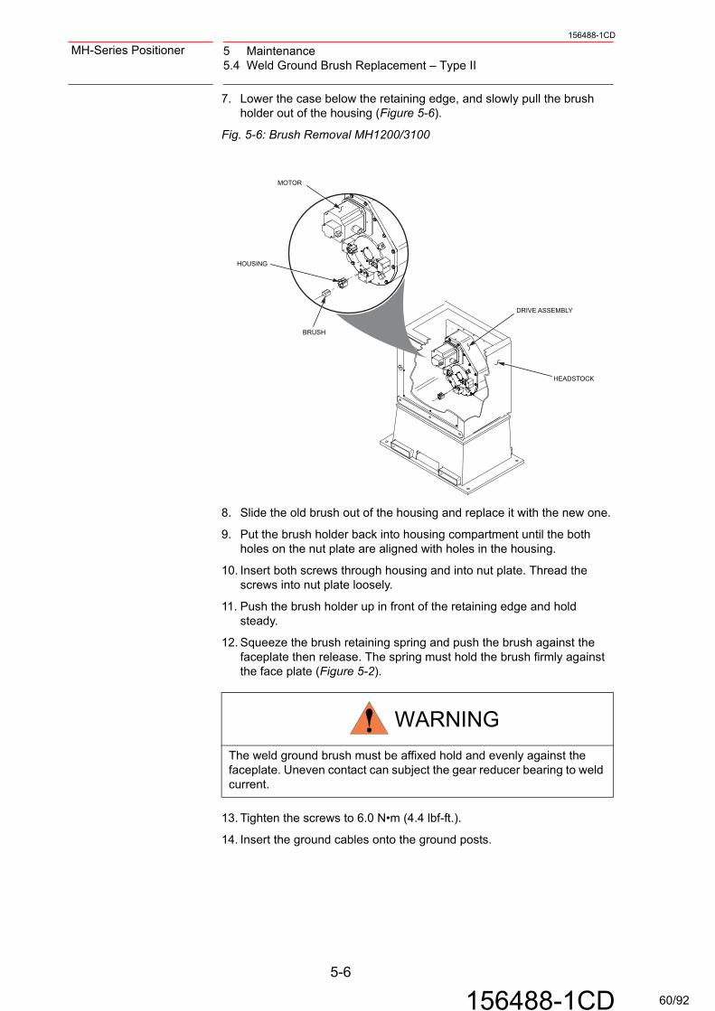
5 Maintenance5.4 Weld Ground Brush Replacement – Type II
156488-1CD
MH-Series Positioner
7. Lower the case below the retaining edge, and slowly pull the brush holder out of the housing (Figure 5-6).
Fig. 5-6: Brush Removal MH1200/3100
8. Slide the old brush out of the housing and replace it with the new one.
9. Put the brush holder back into housing compartment until the both holes on the nut plate are aligned with holes in the housing.
10. Insert both screws through housing and into nut plate. Thread the screws into nut plate loosely.
11. Push the brush holder up in front of the retaining edge and hold steady.
12. Squeeze the brush retaining spring and push the brush against the faceplate then release. The spring must hold the brush firmly against the face plate (Figure 5-2).
13. Tighten the screws to 6.0 N•m (4.4 lbf-ft.).
14. Insert the ground cables onto the ground posts.
WARNING
The weld ground brush must be affixed hold and evenly against the faceplate. Uneven contact can subject the gear reducer bearing to weld current.
MOTOR
BRUSH
HOUSING
HEADSTOCK
DRIVE ASSEMBLY
5-6
156488-1CD 60/92

156488-1CD
MH-Series Positioner 5 Maintenance5.5 Reset Headstock To Home Position
5.5 Reset Headstock To Home Position
The home position on the drive assembly is set in the controller by the operator. Any position of the headstock can be programmed as home. The factory setting of home position is found using the alignment hole, an alignment tool, and the programming pendant.
Resetting of the home position is typically done before new tooling and fixturing is installed, or when the motor has been serviced.
5.5.1 Homing
5.5.1.1 MH90/180/500/1600 – Type I
The factory home position for Type I positioners is located by aligning the homing pin against the housing, after installing the pin in the faceplate hole. Once Home position is found, some minor programming with the programming pendant is required. To reset a MH90/MH180/MH500/MH1600 headstock, proceed as follows:
1. Make sure robot(s) is in home position.
2. Using the programming pendant in TEACH MODE, jog the faceplate slowly until the homing hole is near the home feature on the side of the housing (Figure 5-7).
Fig. 5-7: Home Position - Type I
3. Once the faceplate has been jogged close to the Home position, install the homing pin through the hole in the faceplate. The pin may need to be tapped in with a hammer.
4. Slowly jog the drive assembly until the plastic pin just touches the home feature (Figure 5-8) on the housing. If you go too far the pin will bend, causing a gap at the other end of the pin. Slowly jog the faceplate in reverse rotation until the gap closes.
Now that the faceplate has been set to home position, proceed with Step 5 of resetting instructions:
HOMINGHOLE
HOMINGPIN
HOME FEATURE
ROTATE
5-7
156488-1CD 61/92
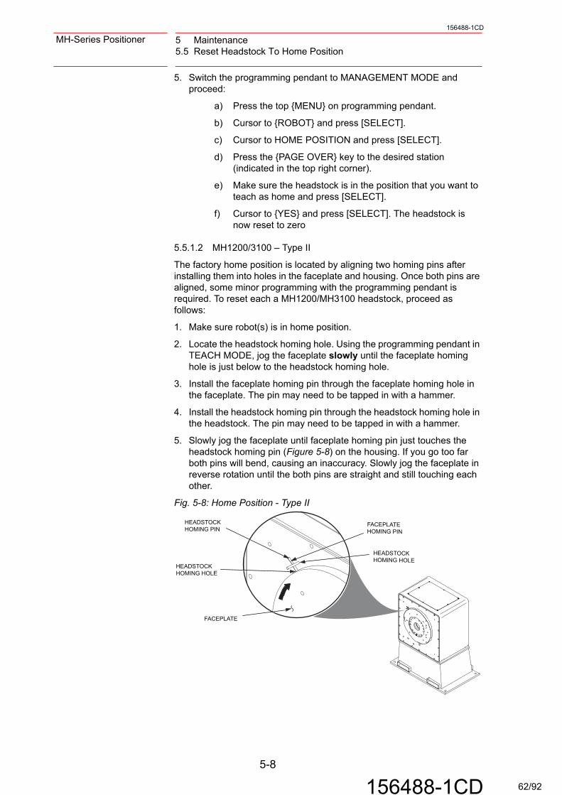
5 Maintenance5.5 Reset Headstock To Home Position
156488-1CD
MH-Series Positioner
5. Switch the programming pendant to MANAGEMENT MODE and proceed:
a) Press the top {MENU} on programming pendant.
b) Cursor to {ROBOT} and press [SELECT].
c) Cursor to HOME POSITION and press [SELECT].
d) Press the {PAGE OVER} key to the desired station (indicated in the top right corner).
e) Make sure the headstock is in the position that you want to teach as home and press [SELECT].
f) Cursor to {YES} and press [SELECT]. The headstock is now reset to zero
5.5.1.2 MH1200/3100 – Type II
The factory home position is located by aligning two homing pins after installing them into holes in the faceplate and housing. Once both pins are aligned, some minor programming with the programming pendant is required. To reset each a MH1200/MH3100 headstock, proceed as follows:
1. Make sure robot(s) is in home position.
2. Locate the headstock homing hole. Using the programming pendant in TEACH MODE, jog the faceplate slowly until the faceplate homing hole is just below to the headstock homing hole.
3. Install the faceplate homing pin through the faceplate homing hole in the faceplate. The pin may need to be tapped in with a hammer.
4. Install the headstock homing pin through the headstock homing hole in the headstock. The pin may need to be tapped in with a hammer.
5. Slowly jog the faceplate until faceplate homing pin just touches the headstock homing pin (Figure 5-8) on the housing. If you go too far both pins will bend, causing an inaccuracy. Slowly jog the faceplate in reverse rotation until the both pins are straight and still touching each other.
Fig. 5-8: Home Position - Type II
HEADSTOCKHOMING PIN
HEADSTOCKHOMING HOLE
FACEPLATE
FACEPLATEHOMING PIN
HEADSTOCKHOMING HOLE
5-8
156488-1CD 62/92

156488-1CD
MH-Series Positioner 5 Maintenance5.5 Reset Headstock To Home Position
6. Switch the programming pendant to MANAGEMENT MODE and proceed:
a) Press top {MENU} key on programming pendant.
b) Cursor to {ROBOT} and press [SELECT].
c) Cursor to HOME POSITION and press [SELECT].
d) Press the {PAGE OVER} key to the desired station (indi-cated in the top right corner).
e) Make sure the headstock is in the position that you want to teach as home and press [SELECT].
f) Cursor to {YES} and press [SELECT]. The headstock is now reset to zero.
Remove the both alignment pins from faceplate headstock.Adjusting Position Limit Switches
The headstock tooling plate can be rotated from the home position (zero degrees) using the programming pendant and the three-position joystick at the operator station. Moving the joystick FORWARD rotates the headstock tooling plate clockwise 30 degrees, while moving it to REVERSE, rotates the tooling plate counterclockwise 30 degrees.
As the tooling plate rotates, a factory installed screw see (Figure 5-9 and Figure 5-10) located at home position activates a limit switch. When activated, the limit switch overrides the safety light curtain functions. That allows operator access to the positioner without disrupting cycle time in the other zones.
Position limit functions are active during rotation of the headstock because the next tooling plate screw has not yet reached a limit switch.Twelve user-defined load positions are available on the tooling plate at 30-degree intervals. One additional set of screws, to be used for a user defined load position, is provided.
NOTE A washer and screw must be used at the user-defined load position holes.
5-9
156488-1CD 63/92

5 Maintenance5.5 Reset Headstock To Home Position
156488-1CD
MH-Series Positioner
5.5.2 MH90/180/500/1600
See Figure 5-9 for setting of position limit switch Type I. See Figure 5-10 for setting of position limit switch Type II.
Fig. 5-9: Position Limit Switch Setting - Type I
5.5.3 MH1200/3100
Fig. 5-10: Position Limit Switch Setting - Type II
SCREW
30º
0º
TOOLINGPLATE
FACTORY PRESETHOME POSITION
LIMIT SWITCH
WASHER
30º
LIMITSWITCH
SCREW
WASHER
BRUSHHOLDER
5-10
156488-1CD 64/92
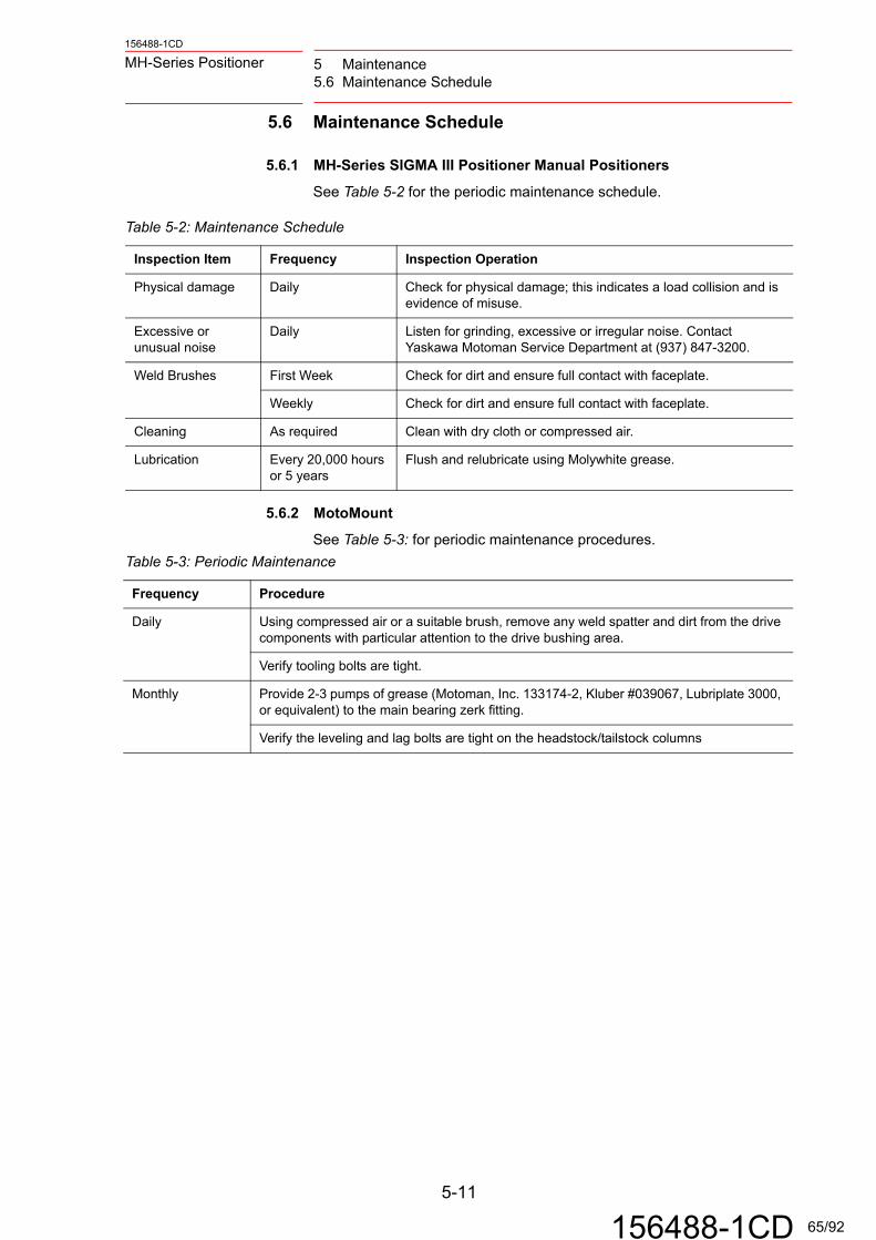
156488-1CD
MH-Series Positioner 5 Maintenance5.6 Maintenance Schedule
5.6 Maintenance Schedule
5.6.1 MH-Series SIGMA III Positioner Manual Positioners
See Table 5-2 for the periodic maintenance schedule.
5.6.2 MotoMount
See Table 5-3: for periodic maintenance procedures.
Table 5-2: Maintenance Schedule
Inspection Item Frequency Inspection Operation
Physical damage Daily Check for physical damage; this indicates a load collision and is evidence of misuse.
Excessive or unusual noise
Daily Listen for grinding, excessive or irregular noise. Contact Yaskawa Motoman Service Department at (937) 847-3200.
Weld Brushes First Week Check for dirt and ensure full contact with faceplate.
Weekly Check for dirt and ensure full contact with faceplate.
Cleaning As required Clean with dry cloth or compressed air.
Lubrication Every 20,000 hours or 5 years
Flush and relubricate using Molywhite grease.
Table 5-3: Periodic Maintenance
Frequency Procedure
Daily Using compressed air or a suitable brush, remove any weld spatter and dirt from the drive components with particular attention to the drive bushing area.
Verify tooling bolts are tight.
Monthly Provide 2-3 pumps of grease (Motoman, Inc. 133174-2, Kluber #039067, Lubriplate 3000, or equivalent) to the main bearing zerk fitting.
Verify the leveling and lag bolts are tight on the headstock/tailstock columns
5-11
156488-1CD 65/92

5 Maintenance5.7 Troubleshooting
156488-1CD
MH-Series Positioner
5.7 Troubleshooting
5.7.1 MH-Series SIGMA III Positioner Manual Positioners
5.7.2 MotoMount
5.7.2.1 High Duty Cycles
High duty cycles under heavy loads and/or dirty operating conditions may cause the drive bushing to wear. This may be indicated by an increase in the tooling position repeatability. Call Yaskawa Motoman Customer Service for details.
Table 5-4: Troubleshooting
Symptom Probable Cause Corrective Action
Motor does not start Loose connection Check all wire connections.
Incorrect wiring Check that system has been wired correctly.
Overload Reduce load or reduce unbalanced load.
Unstable operation Incorrect wiring Inspect and correct wiring across motor terminals L1, L2, L3, and PE.
Motor overheats Excessive ambient temperature
Reduce ambient temperature below 40° C (104° F). Positioner has an operating range of 0 to 45° C (32 to 113°F).
Motor surface is dirty Clean motor surface.
Motor overloaded Reduce load or unbalanced load.
Unusual noise Motor loosely mounted Tighten mounting bolts.
Positioners misaligned Realign headstock/tailstock (see Section 3.4.3, "Leveling the Tailstock")
Noisy bearing Check alignment, noise of bearing, lubrication. Call Yaskawa Motoman Service.
Weld quality bad Brushes misaligned Remove brush(s) and reinstall them properly. Recheck as needed.
5-12
156488-1CD 66/92

156488-1CD
MH-Series Positioner Appendix A Performance ChartsA.1 MH-Series SIGMA III Positioner Manual Drive Assemblies
Appendix A Performance Charts
A.1 MH-Series SIGMA III Positioner Manual Drive Assemblies
A.1.1 MH90
Load CG Offcenterr (mm) Rated W (kgf) Max W (kgf)
40 389 44960 259 29980 195 224100 156 180120 130 150140 111 128160 97 112180 86 100200 78 90220 71 82240 65 75260 60 69280 56 64300 52 60
Holding Torque; Load CG Offcenter
0
50
100
150
200
250
300
350
400
450
500
0 50 100 150 200 250 300
Rated W (kgf)
Max W (kgf)
Maximum Bearing Moment (N*m) = 882
Load CG Overhang (from Tooling Plate)D (mm) Rated W (kgf) Max W (kgf)
50 275 41360 260 38980 233 349100 211 316120 193 289140 178 266160 165 247180 153 230200 144 215220 135 202240 127 191260 120 181280 114 171300 109 163
HTS Applications assume 1/2 load onNote: headstock @ 50 mm, using MotoMount.
2) Rated load based upon 50% maximum bearingmoment.3) Maximum load based upon 75% maximum bearing moment.
Rated Bearing Moment; Load CG Overhang
0
50
100
150
200
250
300
350
400
450
0 50 100 150 200 25 300CG Distance from Tooling Plate, D (mm)
App
licat
ion
Load
, W (k
gf)
Rated W (kgf)
Max W (kgf)
Reflected RatioLoad Inertia Jl/Jm
15 2.516 2.7518 319 3.2521 3.522 3.7524 425 4.2527 4.528 4.7529 5
Note: Maximum recommend inertia ratio is 5.
Allowable Load Inertia
2
2.5
3
3.5
4
4.5
5
5.5
14 15 16 17 18 19 20 21 22 23 24 25 26 27 28 29
Application Inertia, kg*m2
Iner
tia R
atio
, Jl/J
m
Jl/Jm
Rated PeakHolding Torque (N*m)= 153 176
A-1
156488-1CD 67/92

Appendix A Performance ChartsA.1 MH-Series SIGMA III Positioner Manual Drive Assemblies
156488-1CD
MH-Series Positioner
A.1.2 MH180
Rated PeakHolding Torque (N*m)= 275 318
Load CG Offcenterr (mm) Rated W (kgf) Max W (kgf)
40 701 80960 468 54080 351 405100 281 324120 234 270140 200 231160 175 202180 156 180200 140 162220 128 147240 117 135260 108 125280 100 116300 94 108
Holding Torque; Load CG Offcenter
0
100
200
300
400
500
600
700
800
900
0 50 100 150 200 250 300
Rated W (kgf)
Max W (kgf)
Maximum Bearing Moment (N*m) = 882
Load CG Overhang (from Tooling Plate)D (mm) Rated W (kgf) Max W (kgf
50 275 41375 239 358100 211 316125 189 283150 171 256175 156 234200 144 215225 133 199250 124 186275 116 174300 109 163325 103 154350 97 146375 92 138400 88 131425 84 125450 80 120475 76 115500 73 110
HTS Applications assume 1/2 load onNote: headstock @ 50 mm, using MotoMount.
2) Rated load based upon 50% maximum bearingmoment.3) Maximum load based upon 75% maximum bearing moment.
Rated Bearing Moment; Load CG Overhang
0
50
100
150
200
250
300
350
400
450
0 100 200 300 400 500CG Distance from Tooling Plate, D (mm)
App
licat
ion
Load
, W (k
gf)
Rated W (kgf)
Max W (kgf)
Reflected RatioLoad Inertia Jl/Jm
58 2.564 2.7570 376 3.2581 3.587 3.7593 499 4.25105 4.5111 4.75116 5
Note: Maximum recommend inertia ratio is 5.
Allowable Load Inertia
0
1
2
3
4
5
6
58 68 78 88 98 108 118 128
Application Inertia, kg*m2
Iner
tia R
atio
, Jl/J
m
Jl/Jm
A-2
156488-1CD 68/92

156488-1CD
MH-Series Positioner Appendix A Performance ChartsA.1 MH-Series SIGMA III Positioner Manual Drive Assemblies
A.1.3 MH500
Maximum Bearing Moment (N*m) = 2156
Load CG Overhang (from Tooling Plate)D (mm) Rated W (kgf) Max W (kgf)
50 537 80575 478 717100 431 647125 393 589150 361 541175 333 500200 310 465225 289 434250 271 407275 256 384300 242 362325 229 344350 218 327375 207 311400 198 297425 190 284450 182 273475 174 262500 168 252
HTS Applications assume 1/2 load onNote: headstock @ 50 mm, using MotoMount.
2) Rated load based upon 50% maximum bearingmoment.3) Maximum load based upon 75% maximum bearing moment.
Reflected RatioLoad Inertia Jl/Jm
119 2.5131 2.75143 3155 3.25167 3.5179 3.75191 4203 4.25215 4.5227 4.75239 5
Note: Maximum recommend inertia ratio is 5.
Rated Bearing Moment; Load CG Overhang
0
100
200
300
400
500
600
700
800
900
0 100 200 300 400 500CG Distance from Tooling Plate, D (mm)
App
licat
ion
Load
, W (k
gf)
Rated W (kgf)
Max W (kg )
Allowable Load Inertia
2
2.5
3
3.5
4
4.5
5
5.5
110 130 150 170 190 210 230 250
Application Inertia, kg*m2
Iner
tia R
atio
, Jl/J
m
Jl/Jm
A-3
156488-1CD 69/92

Appendix A Performance ChartsA.1 MH-Series SIGMA III Positioner Manual Drive Assemblies
156488-1CD
MH-Series Positioner
A.1.4 MH1200
Holding Torque; Load CG Offcenter
0
500
1000
1500
2000
2500
3000
3500
4000
4500
5000
0 50 100 150 200 250 300
Rated W (kgf)
Max W (kgf)
Rated Bearing Moment; Load CG Overhang
0
500
1000
1500
2000
2500
3000
3500
4000
4500
5000
0 200 400 600 800 1000
CG Distance from Tooling Plate, D (mm)
App
licat
ion
Load
, W (k
gf)
Rated W (kgf)
Max W (kgf)
Rated Peak Holding Torque (N*m)= 1826 2107
Load CG Offcenterr (mm) Rated W (kgf) Max W (kgf)
50 3723 429660 3103 358080 2327 2685100 1862 2148120 1551 1790140 1330 1534160 1164 1343180 1034 1193200 931 1074220 846 976240 776 895260 716 826280 665 767300 621 716
Maximum Bearing Moment (N*m) = 20580
Load CG Overhang (from Tooling Plate)D (mm) Rated W (kgf) Max W (kgf)
50 3174 4761100 2757 4135150 2437 3655200 2183 3274250 1977 2966300 1807 2710350 1664 2495400 1541 2312450 1436 2154500 1344 2016550 1263 1895600 1191 1787650 1127 1691700 1070 1605750 1018 1527800 971 1456850 928 1392900 889 1333950 852 1279
HTS Applications assume 1/2 load onNote: headstock @ 50 mm, using MotoMount.
2) Rated load based upon 50% maximum bearingmoment.3) Maximum load based upon 75% maximum bearing moment.
Allowable Load Inertia
2
2.5
3
3.5
4
4.5
5
299 349 399 449 499 549 599 649 699
Application Inertia, kg*m2
Iner
tia R
atio
, Jl/J
m
Jl/Jm
Reflected RatioLoad Inertia Jl/Jm
299 2.5337 2.75374 3411 3.25449 3.5486 3.75523 4561 4.25598 4.5635 4.75673 5
Note: Max imum recommend inertia ratio is 5.
A-4
156488-1CD 70/92

156488-1CD
MH-Series Positioner Appendix A Performance ChartsA.1 MH-Series SIGMA III Positioner Manual Drive Assemblies
A.1.5 MH1600
Rated Peak Holding Torque (N*m) 2826 3261
Load CG Offcenterr (mm) Rated W (kgf) Max W (kgf)
40 7202 830960 4801 554080 3601 4155100 2881 3324120 2401 2770140 2058 2374160 1800 2077180 1600 1847200 1440 1662220 1309 1511240 1200 1385260 1108 1278280 1029 1187300 960 1108
Maximum Bearing Moment (N*m) = 7056
Load CG Overhang (from Tooling Plate)D (mm) Rated W (kgf) Max W (kgf)
50 1284 192760 1240 186080 1160 1740100 1090 1635120 1028 1541140 972 1458160 922 1383180 877 1316200 836 1255220 799 1199240 765 1148260 734 1101280 705 1058300 679 1018
Note: HTS Applications assume 1/2 load onheadstock @ 50 mm, using MotoMount.2) Rated load based upon 50% maximum bearingmoment.3) Maximum load based upon 75% maximum bearing moment.
Reflected RatioLoad Inertia Jl/Jm
678 2.5747 2.75817 3887 3.25957 3.5
1027 3.751096 41166 4.251236 4.51306 4.751376 5
Note: Maximum recommended inertia ratio is 5.
Rated Bearing Moment; Load CG Overhang
0
500
1000
1500
2000
2500
0 50 100 150 200 250 300CG Distance from Tooling Plate, D (mm)
App
licat
ion
Load
, W (k
gf)
Rated W (kgf)
Max W (kgf)
Allowable Load Inertia
2.5
3
3.5
4
4.5
5
5.5
678 778 878 978 1078 1178 1278 1378 1478
Application Inertia, kg*m2
Iner
tia R
atio
, Jl/J
m
Series1
Holding Torque; Load CG Offcenter
0
1000
2000
3000
4000
5000
6000
7000
8000
9000
0 50 100 150 200 250 300
CG Offcenter, r (mm)
App
licat
ion
Load
, W (k
gf) Rated W (kgf)
Max W (kgf)
A-5
156488-1CD 71/92

Appendix A Performance ChartsA.1 MH-Series SIGMA III Positioner Manual Drive Assemblies
156488-1CD
MH-Series Positioner
A.1.6 MH3100
Holding Torque; Load CG Offcenter
0
2000
4000
6000
8000
10000
12000
14000
0 50 100 150 200 250 300
Rated W (kgf)
Max W (kgf)
Rated Bearing Moment; Load CG Overhang
0
500
1000
1500
2000
2500
3000
3500
4000
4500
5000
0 200 400 600 800 1000
CG Distance from Tooling Plate, D (mm)
App
licat
ion
Load
, W (k
gf)
Rated W (kgf)
Max W (kgf)
Allowable Load Inertia
2
2.5
3
3.5
4
4.5
5
5.5
3000 3500 4000 4500 5000 5500 6000 6500
Application Inertia, kg*m2
Iner
tia R
atio
, Jl/J
m
Jl/Jm
Rated PeakHolding Torque (N*m)= 5479 6322
Load CG Offcenterr (mm) Rated W (kgf) Max W (kgf)
50 11170 1288860 9308 1074080 6981 8055100 5585 6444120 4654 5370140 3989 4603160 3491 4028180 3103 3580200 2792 3222220 2539 2929240 2327 2685260 2148 2479280 1995 2301300 1862 2148
Maximum Bearing Moment (N*m) = 20580
Load CG Overhang (from Tooling Plate)D (mm) Rated W (kgf) Max W (kgf)
50 3174 4761100 2757 4135150 2437 3655200 2183 3274250 1977 2966300 1807 2710350 1664 2495400 1541 2312450 1436 2154500 1344 2016550 1263 1895600 1191 1787650 1127 1691700 1070 1605750 1018 1527800 971 1456850 928 1392900 889 1333950 852 1279
Note: 1) HTS Applications assume 1/2 load onheadstock @ 50 mm, using MotoMount.2) Rated load based upon 50% maximum bearingmoment.3) Maximum load based upon 75% maximum bearing moment.
Reflected RatioLoad Inertia Jl/Jm
3058 2.53394 2.753730 34066 3.254402 3.54738 3.755073 45409 4.255745 4.56081 4.756417 5
Note: Maximum recommend inertia ratio is 5.
A-6
156488-1CD 72/92

156488-1CD
MH-Series Positioner Appendix B Illustrated Parts listB.1 Introduction
Appendix B Illustrated Parts list
B.1 Introduction
This Illustrated Parts List identifies, describes, and illustrates detail parts of the main assemblies for the MH-Series Positioner manufactued by Yaskawa Motoman.This list provides parts identification and descriptive information for use in provisioning, requesting, purchasing, storing, and issuing spare parts.
B.1.1 Contents
The parts list contains a breakdown of the equipment into detail parts. All parts of the equipment are listed except the following:1. Standard hardware items (attaching parts) such as nuts, screws,
washers, etc., which are available commercially.
2. Bulk items such as wire, cable, sleeving, tubing, etc., which are also commercially available.
3. Permanently attached parts which lose their identity by being welded, soldered, riveted, etc., to other parts, or assemblies.
B.1.2 Parts List
This form is divided into four columns as follows:
“Figure - Item Number” Column• This column lists the figure number of the illustration applicable to a
particular parts list and also identifies each part in the list by an item number. These item numbers also appear on the illustration. Each item number on the illustration is connected to the part to which it pertains by a leader line and arrow. Thus, the figure and item num-bering system ties the parts list to the illustrations and vice versa
Part Number” Column• All part numbers appearing in this column are Yaskawa Motoman
part numbers.
“Description” Column• The item nomenclature appears in this column.
“QTY” Column• This column indicates the quantity of parts required for an assembly
or subassembly in which the part appears. This column does not necessarily reflect the total used in the complete end item.
B-1
156488-1CD 73/92

Appendix B Illustrated Parts listB.1 Introduction
156488-1CD
MH-Series Positioner
B.1.3 Symbols and Abbreviations
The following is a list of symbols and abbreviations used in the parts list.
.
• amp - ampere • in - Inch
• AC - Alternating Current • m - Meter
• cyl - Cylinder • mm - millimeter
• DC - Direct Current • No - Number
• fig - Figure • psi - Pounds per Square Inch
• hex - Hexagon • v - Voltage
• ID - Inside Diameter
NOTEThe MH90 and MH180 drive assemblies have the same common parts except for the gear reducer and gear pinion components.
B-2
156488-1CD 74/92

156488-1CD
MH-Series Positioner Appendix B Illustrated Parts listB.1 Introduction
Fig. B-1: MH90/180 Drive Assembly Components
3
4
7
16
811
18
6
910
5
6
5
12
13
14
15
B-3
156488-1CD 75/92

Appendix B Illustrated Parts listB.1 Introduction
156488-1CD
MH-Series Positioner
( ) optional configuration- = Not Shown
Table B-1: Parts List - MH90/180 Drive Assembly Components
FIGURE &ITEM NUMBER
PART NUMBER DESCRIPTION QTY
B-1-1 152543-1 DRIVE ASSY, HEADSTOCK 90 kg, SERVO Ref
-2 152543-2 DRIVE ASSY, HEADSTOCK 180 kg, SERVO Ref
3 149568-4 MOTOR, AC SERVO, SIGMA III 1
4 151093-1 HOUSING, MACHINED 1
5 144370-1 TERMINAL, QUICK, DISCONNECT 2 (4)
6 143963-1 SWITCH, LIMIT, MINIATURE 2
7 144372-1 BRUSH, HOLDER 1 (2)
8 144371-1 BRUSH, GROUND METAL 1 (2)
9 146122-1 SEAL KIT, RV80E 1
10 145896-1 PIN, HOMING 1
11 145888-1 PLATE, FACE 1
12 146685-1 COLUMN, HEADSTOCK 1
13 145260-1 BOLT, LEVELING 4
14 130429-11 NUT, HEX JAM, M20 4
15 146456-1 WASHER, SQUARE, 3/8 ID 4
16 145913-1 REDUCER, RV, HEADSTOCK, MH90 1
-17 145913-2 REDUCER, RV, HEADSTOCK, MH180 1
18 145911-1 GEAR, PINION, INPUT, MH90 1
-19 145911-2 GEAR, PINION, INPUT, MH180 1
-20 151248-1 CABLE, ASSY, POWER, 0.8 KW 1
-21 152454-1 CABLE, ASSY, ENCODER, LIM-SWITCH 1
-22 146482-1 CABLE, SWITCH 1
-23 479348-2 CABLE, BATTERY 1
B-4
156488-1CD 76/92

156488-1CD
MH-Series Positioner Appendix B Illustrated Parts listB.1 Introduction
Fig. B-2: MH500 Drive Assembly Components
13
5
79
8
12
2
3
6
1011
4
6
4
15
16
17
B-5
156488-1CD 77/92

Appendix B Illustrated Parts listB.1 Introduction
156488-1CD
MH-Series Positioner
( ) optional configuration- = Not Shown
Table B-2: Parts List - MH500 Drive Assembly Components
FIGURE &ITEM NUMBER
PART NUMBER DESCRIPTION QTY
B-2-1 152547-1 DRIVE ASSY, HEADSTOCK 500 kg, SERVO ref
2 149568-6 MOTOR, AC SERVO, SIGMA III 1
3 141575-2 GEAR, INPUT, GEAR REDUCER 1
4 144370-1 TERMINAL, QUICK, DISCONNECT 4 (6)
5 151042-1 HOUSING, MACHINED 1
6 143963-1 SWITCH, LIMIT, MINIATURE 2
7 144372-1 BRUSH, HOLDER 2 (3)
8 144371-1 BRUSH, GROUND METAL 2 (3)
9 141574-2 REDUCER, RV, HEADSTOCK 1
10 146123-1 SEAL KIT, RV80E 1
11 145896-1 PIN, HOMING 1
12 145914-1 PLATE, FACE, 450 kg, HEADSTOCK 1
13 146467-1 COLUMN, HEADSTOCK, 500 kg 1
-14 146467-2 COLUMN, HEADSTOCK, 500 kg, FABWORLD II CELL
1
15 145260-1 BOLT, LEVELING 4
16 130429-11 NUT, HEX JAM, M20 4
17 146456-1 WASHER, SQUARE, 3/8 ID 4
-18 152800-1 CABLE, ASSY, POWER, 1.3 KW, 500 kg 1
-19 152454-1 CABLE, ASSY, ENCODER, LIM-SWITCH 1
-20 146482-1 CABLE, SWITCH 1
-21 479348-2 CABLE, BATTERY 1
B-6
156488-1CD 78/92

156488-1CD
MH-Series Positioner Appendix B Illustrated Parts listB.1 Introduction
Fig. B-3: MotoMount Tailstock Components - 90/180/500 kg
( ) optional configuration- = Not Shown
7
12
13
14
15
Table B-3: Parts List - MotoMountTM Tailstock Components – 90/180/500 kg
FIGURE &ITEM NUMBER
PART NUMBER DESCRIPTION QTY
1 148757-1 SHAFT,FLANGED,MTG,MOTOMOUNT,TS 1
2 148136-2 BEARING,SPHERICAL ROLLER 1
3 148135-1 SCREW,SET,CONE PT,M8X6 1
4 148124-1 PIN,LOCATOR,16MM 1
5 155870-1 ADAPTER,BLOCK,TAILSTOCK,GEN2 1
6 156164-1 RETAINER,TAILSTOCK BEARING 2
7 146953-3 RING,RETAINING,EXTERNAL,55 1
8 407249-3 SCREW,SHC,M6X12 6
9 470602-1 WASHER,CONICAL SPRING, M6 8
10 470541-1 SEAL,FACE, SPHERICAL BEARING 2
11 407249-1 SCREW, SHC, M6x1 X 8 2
12 155941-1 COLUMN,TAILSTOCK,MHT-500,GEN 2 1
13 145260-1 BOLT,LEVELING,M20X50 4
14 130429-11 NUT,HEX JAM,M20,ZP 4
15 146456-1 WASHER,SQUARE,3/8IDX1/4X2X2 4
B-7
156488-1CD 79/92

Appendix B Illustrated Parts listB.1 Introduction
156488-1CD
MH-Series Positioner
Fig. B-4: MH1600 Drive Assembly Components
2
7
5
6
9
8
16
15
17
18
12
4 3
14
13
10
11
19
20
B-8
156488-1CD 80/92

156488-1CD
MH-Series Positioner Appendix B Illustrated Parts listB.1 Introduction
( ) optional configuration- = Not Shown
Table B-4: Parts List - MH1600 Drive Assembly Components
FIGURE &ITEM NUMBER
PART NUMBER DESCRIPTION QTY
B-4-1 152675-1 DRIVE ASSY, HEADSTOCK, 1600 KG REF
2 149568-8 MOTOR, AC SERVO SIGMA III 1
3 152538-1 ADAPTER, FLYWHEEL, MRM2-250/750 MRM2-250/750-M3X
1
4 144370-1 TERMINAL, QUICK DISC, WELD GRND 4
5 144372-1 BRUSH HOLDER 2
6 144371-1 BRUSH, GROUND 2
7 145896-1 PIN, HOMING 1
8 152691-1 PLATE, FACE, MH1600 DRIVE ASSY 1
9 133937-1 FITTING, ZERK, GREASE 1
10 151592-7 REDUCER, RV 1
11 146924-1 SEAL, O-RING 265ID 1
-12 146482-1 CABLE ASSY, LIMIT SWITCH 1
13 143963-1 SWITCH, LIMIT, MINIATURE ROLLER ACTUATED, MICHROCHANGE
2
14 152690-1 HOUSING, MACHINED 1
15 151593-7 GEAR, INPUT, PINION 1
16 146647-1 COLUMN, HEADSTOCK 1
17 140784-1 SCREW, LEVELING 4
18 130440-12 NUT, HEX, M30 4
19 146456-2 WASHER, SQUARE 4
20 479348-2 BATTERY ASSY 1
21 146818-2 PLATE, MTG, POWER/ENCODER 1
-22 152454-1 CABLE ASSY, PIGTAIL 1
-23 149679-4 CABLE ASSY, PIGTAIL 1
B-9
156488-1CD 81/92

Appendix B Illustrated Parts listB.1 Introduction
156488-1CD
MH-Series Positioner
Fig. B-5: MH1200 / 3100 Headstock Components
3
5
4
6
7
8
1
B-10
156488-1CD 82/92
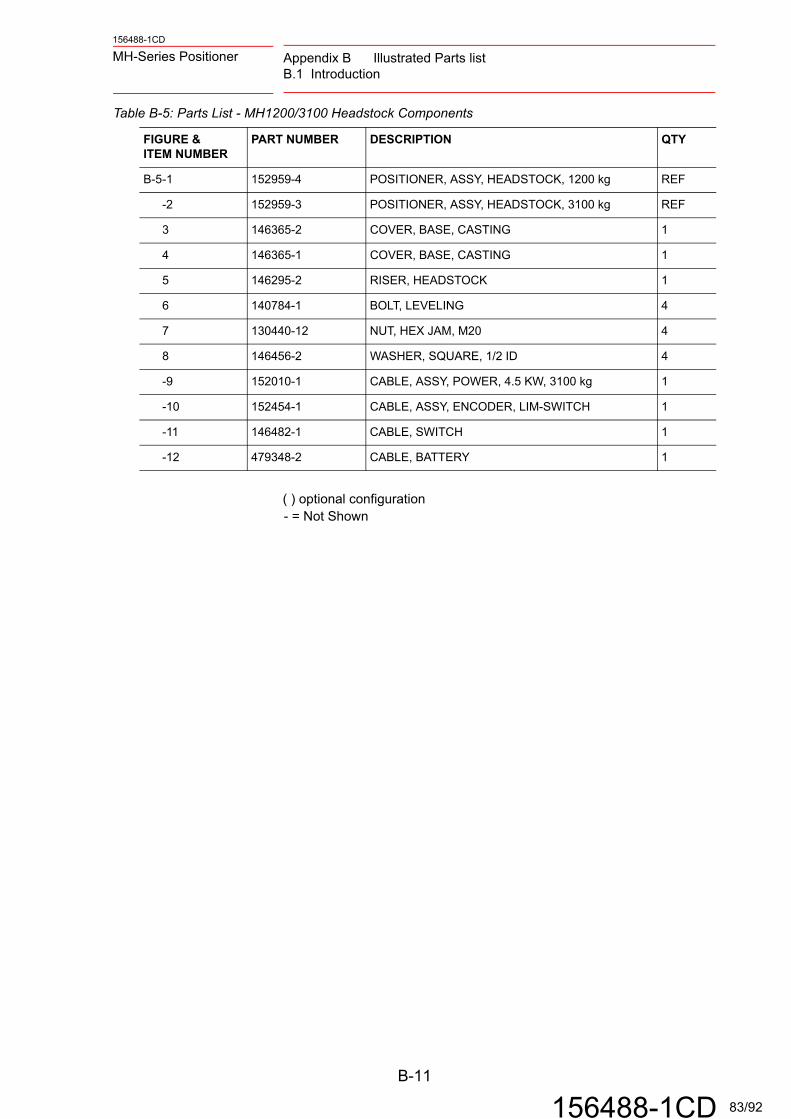
156488-1CD
MH-Series Positioner Appendix B Illustrated Parts listB.1 Introduction
( ) optional configuration- = Not Shown
Table B-5: Parts List - MH1200/3100 Headstock Components
FIGURE &ITEM NUMBER
PART NUMBER DESCRIPTION QTY
B-5-1 152959-4 POSITIONER, ASSY, HEADSTOCK, 1200 kg REF
-2 152959-3 POSITIONER, ASSY, HEADSTOCK, 3100 kg REF
3 146365-2 COVER, BASE, CASTING 1
4 146365-1 COVER, BASE, CASTING 1
5 146295-2 RISER, HEADSTOCK 1
6 140784-1 BOLT, LEVELING 4
7 130440-12 NUT, HEX JAM, M20 4
8 146456-2 WASHER, SQUARE, 1/2 ID 4
-9 152010-1 CABLE, ASSY, POWER, 4.5 KW, 3100 kg 1
-10 152454-1 CABLE, ASSY, ENCODER, LIM-SWITCH 1
-11 146482-1 CABLE, SWITCH 1
-12 479348-2 CABLE, BATTERY 1
B-11
156488-1CD 83/92
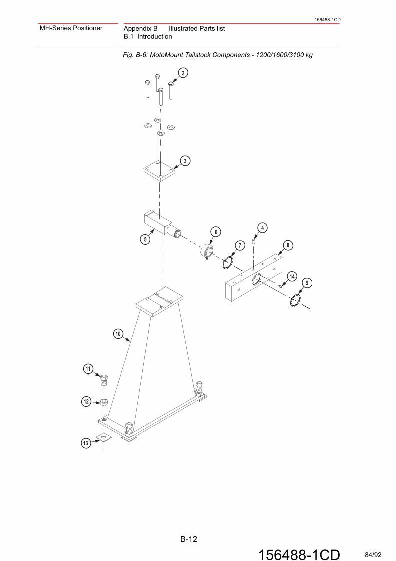
Appendix B Illustrated Parts listB.1 Introduction
156488-1CD
MH-Series Positioner
Fig. B-6: MotoMount Tailstock Components - 1200/1600/3100 kg
2
3
4
56
7
9
7
10
11
12
13
14
8
B-12
156488-1CD 84/92

156488-1CD
MH-Series Positioner Appendix B Illustrated Parts listB.1 Introduction
( ) optional configuration- = Not Shown
Table B-6: Parts List - MotoMount Tailstock Components - 1200/1600/3100 kg
FIGURE &ITEM NUMBER
PART NUMBER DESCRIPTION QTY
B-6-1 146964-3 ADAPTER, ASSY, TAILSTOCK, MOTOMOUNT HD
REF
2 131275-1 SCREW, HHC, M20 X 120 4
3 146951-1 CLAMP, SHAFT 1
4 148124-1 PIN, LOCATING, DIA16 1
5 146950-4 SHAFT, SQUARE 1
6 148136-1 BEARING, SPHERICAL, ROLLER 1
7 146940-4 RING, RETAINING, INTERNAL 1
8 146965-3 ADAPTER, TAILSTOCK 1
9 146953-3 RING, RETAINING, EXTERNAL 1
10 146949-1 COLUMN, TAILSTOCK, 1
11 140784-1 BOLT, LEVELING 4
12 130440-12 NUT, HEX JAM, M20 4
13 146456-2 WASHER, SQUARE, 1/2 ID 4
14 148135-1 SCREW, SET, M8 X 6, POINTED 1
B-13
156488-1CD 85/92

Appendix B Illustrated Parts listB.1 Introduction
156488-1CD
MH-Series Positioner
Fig. B-7: Type II Drive Assembly Components
1 23 4 5 6
7
8
2120
18
13
11
1010
22
19
15
16
17
9
B-14
156488-1CD 86/92

156488-1CD
MH-Series Positioner Appendix B Illustrated Parts listB.1 Introduction
( ) optional configuration- = Not Shown
Table B-7: Type II Drive Assembly Components
FIGURE &ITEM NUMBER
PART NUMBER DESCRIPTION QTY
B-71 140837-6 PIN, DOWEL 2
2 152562-1 PLATE, MTG, DRIVE ASSY, TYPE II SIGMA III 1
3 146010-1 GEAR ASSY, IDLER DRIVE ASSY (MH-3100) 1
4 140568-4 SEAL, OIL 1
5 146743-1 GEAR ASSY DRIVE 1
6 146009-1 REDUCER, RV, POSITIONER 1
7 146022-1 POST, MGT, DRIVE, GEAR RV 1
8 146198-1 PLATE, DRIVE ASSY MSR-500/100 & MH-1000/3000
1
9 146199-1 PLATE, FACE, 2000KG HEADSTOCK 1
10 145785-1 FITTING, PLUG 3
11 146742-1 GEAR ASSY, COMPOUND, DRIVE ASSY HIGH SPEED (MH-1200)
1
-12 146742-2 GEAR ASSY, COMPOUND, DRIVE ASSY LOW SPEED (MH-3100)
1
13 152861-2 MOTOR ASSY, TYPE II SIGMA III (MH-1200) 1
-14 152861-1 MOTOR ASSY, TYPE II SIGMA III (MH-3100) 1
15 146015-2 BRACKET, MTG, BRUSH HOLDER DRIVE ASSY 3
16 146014-1 BLOCK, MTG, LIMIT SWITCH DRIVE ASSY 1
17 143963-1 SWITCH, LIMIT, MINIATURE ROLLER ACTUATED, MICHROCHANGE
2
18 144371-1 BRUSH, GROUND, METAL 3
19 144372-1 BRUSH HOLDER 3
20 144370-1 TERMINAL, QUICK DISC, WELD GRND 6
21 146012-2 PLATE, GROUNDING BRUSH DUAL CHANNEL 1
22 146010-1 HOUSING, CAST, POSITIONER DRIVE ASSY 1
B-15
156488-1CD 87/92
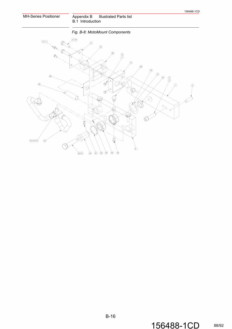
Appendix B Illustrated Parts listB.1 Introduction
156488-1CD
MH-Series Positioner
Fig. B-8: MotoMount Components
21
19
17
16
3
4
6
28
31
1178
9 10
7
8
1824202322 21
12131415
30
29
26
2527
5
B-16
156488-1CD 88/92

156488-1CD
MH-Series Positioner Appendix B Illustrated Parts listB.1 Introduction
( ) optional configuration- = Not Shown
Table B-8: Parts List - MotoMount Components
FIGURE &ITEM NUMBER
PART NUMBER DESCRIPTION QTY
B-8-1 145708-1 BLOCK,MTG,MOTO-MOUNT 1
-2 151233-1 PIN,DOWEL,M12X40,MODIFIED 2
3 472303-9 SCREW,SHC,M12X50,CLASS 12.9 2
4 471075-1 WASHER,CONICAL SPRING,GTS12 2
5 155872-1 BLOCK,MOUNTING,FIXTURE,GEN2 1
6 146497-1 COVER,DUST,CAM BLOCK 1
7 139965-1 SCREW,HHC,M6X10,CLASS 8.8 4
8 470602-1 WASHER,CONICAL SPRING,GTS6 4
9 132614-1 SCREW,HHC,M10X40,CLASS 8.8 2
10 470541-1 WASHER,CONICAL SPRING,GTS10 2
11 146503-1 PLATE,SIDE,BLOCK 1
12 130887-11 CABLE,WELD,4/0,1FT 2
13 131272-1 SCREW,HHC,M12X25,ZP,CLASS 8.8 3
14 479148-7 WASHER,LOCK,M12 3
15 147462-1 WASHER,M12,HIGH STRENGH 5
16 145848-1 SEAL,O-RING,34.29MM ID X 5.33 1
17 145848-2 SEAL,O-RING,43.82MM ID X 5.33 1
18 133937-1 FITTING,ZERK,GREASE,1/8(R)PT 1
19 145849-1 SPACER,CUSTOM,25.0ID X 8.0LG 1
20 130398-4 RING,RETAINING,INTERNAL,42MM 1
21 132049-1 WASHER,CONICAL SPRING,GTS16 1
22 131274-5 SCREW,HHC,M16X65,ZP,CL 8.8 1
23 145724-1 BUSHING,BEARING,MAIN 1
24 145753-1 BEARING,SPHERICAL,25ID 1
25 148135-1 SCREW,SET,M8X6,POINTED 1
26 148124-1 PIN,LOCATOR,16mm 1
27 132613-3 SCREW,SET,M8X10 2
28 145710-1 BLOCK,GUIDE 1
29 146496-1 PLATE,CAM BLOCK 1
30 146993-1 PIN,DOWEL,WHISTLE STOP 1
31 145725-1 BUSHING,BLOCK,MOTOMOUNT 1
B-17
156488-1CD 89/92

Appendix B Illustrated Parts listB.1 Introduction
156488-1CD
MH-Series Positioner
Fig. B-9: MotoMount HD Drive Components
( ) optional configuration- = Not Shown
7
9
10
8
5
3
2
4
6
11
Table B-9: Parts List - MotoMount HD Drive Components
FIGURE &ITEM NUMBER
PART NUMBER DESCRIPTION QTY
B-9-1 146200-1 ADAPTER, ASSY, MOTOMOUNT HD REF
2 146193-1 HUB, MOUNTING 1
3 146195-1 BLOCK, GUIDE 1
4 146928-1 BEARING, CAM FOLLOWER 1
5 145751-1 PIN, LOCATING, DIA. 16 MM HEAD 1
6 146196-1 BLOCK, MOUNTING, FIXTURE 1
7 146927-1 BEARING, SPHERICAL, PRECISION, 50 MM ID
1
8 146940-1 RING, RETAINING, INTERNAL, 80 MM 1
9 130330-7 NUT, BEARING 1
10 130887-11 CABLE, WELD, 4/0, 1 FT 1
B-18
156488-1CD 90/92

156488-1CD
MH-Series Positioner Appendix B Illustrated Parts listB.1 Introduction
Fig. B-10: Slip Ring Kit Components
( ) optional configuration- = Not Shown
2
3
4
5
6
7
8
Table B-10: Parts List - Slip Ring Kit Components
FIGURE &ITEM NUMBER
PART NUMBER DESCRIPTION QTY
B-10-1 148634-1 ACCESSORY, SLIP RING, MOTOMOUNT HD REF
2 148636-1 SUPPORT, GUARD, SLIP RING 1
3 148635-1 GUARD, SLIP RING 1
4 148848-1 SLIP RING ASSY, MOTOMOUNT HD 1
5 146913-2 FITTING, NIPPLE, PIPE, BRASS, 3/8-INCH 1
6 148847-1 RING, RETAINING, EXT, 42 MM SHAFT 1
7 148637-1 GUIDE, OUTLET, PIPE 1
8 148849-1 PLATE, CLAMP, DRIVE, DOG 1
B-19
156488-1CD 91/92

MH-SERIES SIGMA III POSITIONER
1156488-1CDMANUAL NO.
Specifications are subject to change without noticefor ongoing product modifications and improvements.
92/92