Embed Size (px)
Citation preview

8/28/00
MHG-LR MODULAR TURBO
REFRIGERATING® ICE MACHINE
Manual Part Number 12A4171M12
Service Manual
$5000

NOTICE
This manual is the property of the owner of this particular Tube-Ice®
machine.
Model #____________________ Serial #____________________.
It is to be left on the premises with this machine at all times. After start-
up, it should be stored in a safe place where it can be readily available
when needed for future reference in maintaining troubleshooting or
servicing.
Failure to comply with this notice will result in unnecessary
inconvenience and possible additional expenses.
This manual is intended as an informational tool for the installation,
operation, maintenance, troubleshooting, and servicing of this equipment.
If an existing situation calls for additional information not found herein,
we suggest that you contact your distributor first. If further assistance or
information is needed, please feel free to contact the factory at 502-635-
3000 or FAX at 502-635-3024.
IMPORTANT: The Warranty Registration/Start-Up Report found in the
front of this manual is to be completed and returned to the factory
promptly after the official start-up.
Please return to: VOGT ICE, LLC
1000 W. Ormsby Ave.
Louisville, KY 40210

8/28/00
Warranty Registration / Start-Up Form (Medium & Large Machines)
Model Number: __________________________ Serial Number: __________________________
This form must be filled out completely and signed by the customer in order to assure acceptance by Vogt.
Date of Start-Up: _______________________________ Form Completed By: _____________________________________
AC Condenser Model Number: _____________________ AC Condenser Serial Number: _____________________________
Water Treatment System? Yes No Manufacturer: ____________________ Model: ________________________
Bin Manufacturer: _______________________ Model: _________________________ Bin Capacity: _______ lbs.
Distributor
Company Name: ____________________________________________ Phone: _______________________
Address: ____________________________________ City: _________________________ State: ___________ Zip: ___________
Service Company
Company Name: ____________________________________________ Phone: _______________________
Address: ____________________________________ City: _________________________ State: ___________ Zip: ___________
Customer (location of equipment)
Company Name: ____________________________________________ Phone: _______________________
Address: ____________________________________ City: _________________________ State: ___________ Zip: ___________
PRE-OPERATION CHECK Service Manual on hand
Machine room suitable 50°F minimum, 110°F maximum
Power Supply ______ V _____ PH _____ Hz (machine not running)
Compressor crankcase heater on 12 hour minimum
All valves opened or closed as tagged
Solenoid valve stems in auto position
System leak checked/tight
Auxiliary equipment overloads wired into control circuit
Water supply and drains connected properly
Sufficient make-up water supply (minimum 30 PSIG)
Instruction manual and warranty certificate left on-site
Name of person left with: __________________________________
OPERATION CHECK Power Supply ______ V _____ PH _____ HZ (machine running)
Pump , cutter & other motor direction of rotation correct
Water pump amps RLA__________ Actual __________
Condenser motor amps (if applicable) _________
Incoming potable water temperature: _____°F
All water distribution in place (visually inspected)
Make-up water float valve operates properly
Clear ice Yes No
Hour meter in control panel connected and operating
Suction Pressure: End of freeze ________ End of harvest ________
Discharge Pressure: End of freeze ________ End of harvest ________
Test
Cycle
Make-up
Water Temp
Freeze Time
Min/Sec
Harvest Time
Min/Sec
First Ice Out
Min/Sec
All Ice Out
Min/Sec
Avg. Hole
Size
Ice
Lb. Per Harvest
Ice
Lb. Per Day
#1
#2
#3
#4
Note: Ice lb. per day can be found by:
Remarks:
Technician Signature: ___________________________ End User Signature:_____________________________ I certify that I have performed all of the above procedures.
1440×+ me)harvest ti time(freeze
harvestper lb. ice
Vogt Ice L.L.C. 1000 W. Ormsby
Louisville, KY 40210
(502) 635-3235 FAX #502-635-3024
THIS FORM MUST BE SENT TO
VOGT TO ACTIVATE WARRANTY
Vogt Order Number: ____________________


3/30/10
VOGT ICE, LLC, located in
Louisville, Kentucky since 1880.
Sales - (800) 853-8648
Parts and Service - (502) 635-3000
Since 1880, Manufacturers of Quality
Tube-Ice® Machines

Vogt
Turbo Refrigerating Ice Machines
Installation, Service Manual and Parts Catalog #12A4171M12
Modular Lowside Model

MHG-LR Service Manual
TABLE OF CONTENTS
3/30/10
i
TABLE OF CONTENTS
Vogt®
TUBE-ICE® MACHINES
MHG-LR Modular Model Page No.
1. INTRODUCTION
A Brief History Of Our Company ..................................................................................................................................1-1
Preview ...........................................................................................................................................................1-1
Important Safety Notice ..................................................................................................................................................1-2
Special Precautions To Be Observed When Charging Refrigeration Systems............................................................1-2
Safety Symbols and What They Mean ...........................................................................................................................1-3
Assembly Drawing Model MHGFL, FIGURES 1-1, 1-2, 1-3 & 1-4 ............................................................................1-4 to 1-6
2. RECEIPT OF YOUR VOGT-ICE MACHINE
Inspection ...........................................................................................................................................................2-1
Description of Machine....................................................................................................................................................2-1
Safety Tags and Labels....................................................................................................................................................2-1
Safety Valves ...........................................................................................................................................................2-1
Rated Capacity ...........................................................................................................................................................2-2
Turbo Modular Machines Unified Number Model Structure ......................................................................................2-3
3. INSTALLING YOUR VOGT-ICE MACHINE
Machine Room ...........................................................................................................................................................3-1
Lifting Procedures ...........................................................................................................................................................3-1
Modular Unit Lifting Procedure FIGURE 3-1 ..........................................................................................................3-2
Foundation Layout...........................................................................................................................................................3-2
Foundation Height- Modular Unit, FIGURE 3-2..........................................................................................................3-3
Mounting Detail- Modular Unit, FIGURE 3-3 ..........................................................................................................3-4
Piping and Drain Connections, TABLE 3-1 ..................................................................................................................3-4
Make-up Water In ...........................................................................................................................................................3-5
Water Tank Drain ...........................................................................................................................................................3-5
Water Tank Overflow......................................................................................................................................................3-5
Water Piping, FIGURE 3-4.............................................................................................................................................3-5
Wet Suction and Liquid Stop Valve................................................................................................................................3-6
Compressor Unloading ....................................................................................................................................................3-6
Safety Valves ...........................................................................................................................................................3-6
Spacing and Connection Diagram, (Flooded) FIGURE 3-5..........................................................................................3-7
Customer Piping-LR, (Flooded) FIGURE 3-6 ...............................................................................................................3-8
Piping Schematic (Flooded), FIGURE 3-7 .....................................................................................................................3-9
Wiring and Electrical Connection ..................................................................................................................................3-10
Typical Master Panel and Module Connection, FIGURE 3-8......................................................................................3-10
Master Panel Field Connections, Figure 3-9.................................................................................................................3-11
Master Panel Field Connections, (Detail) FIGURE 3-10 ..............................................................................................3-12

MHG-LR Service Manual
TABLE OF CONTENTS
ii
Page No.
INSTALLING YOUR TUBE-ICE MACHINE (con’t)
Master Panel Field Ethernet Connections (Detail) Figure 3-11 ................................................................................3-13
Modular Panel Field Connections Figure 3-12...........................................................................................................3-14
Electrical Specifications, Table 3-2 .............................................................................................................................3-15
Phase Check ...........................................................................................................................................................3-15
Voltage Unbalance........................................................................................................................................................3-15
Current Unbalance ......................................................................................................................................................3-16
Screw Conveyor ...........................................................................................................................................................3-16
Startup Checklist ..........................................................................................................................................................3-18
4. HOW YOUR TUBE-ICE MACHINE WORKS
Principle of Operation .....................................................................................................................................................4-1
Freeze Period ...........................................................................................................................................................4-1
Dry Out Period ...........................................................................................................................................................4-2
Harvest Period ...........................................................................................................................................................4-2
Piping Nomenclature, (Dedicated High Side) Table 4-1................................................................................................4-2
Piping Schematic FIGURE 4-1......................................................................................................................................4-3
Water Piping Schematic, FIGURE 4-2...........................................................................................................................4-4
Typical High Side Layout FIGURE 4-3 .........................................................................................................................4-4
5. START-UP AND OPERATION
Refrigeration System Review..........................................................................................................................................5-1
Refrigerant Charge..........................................................................................................................................................5-2
Ammonia Specification By Grade, Table 5-1.................................................................................................................5-2
Special Precautions ..........................................................................................................................................................5-2
Charging From Tank Truck (dedicated high side only)................................................................................................5-2
Charging From Cylinders (dedicated high side only) ...................................................................................................5-3
Start-up Procedure .........................................................................................................................................................5-5
Thaw Gas Regulating and Suction By-pass Valve Adjustment ...................................................................................5-5
Shut-down Procedure .....................................................................................................................................................5-6
Operating Tips ...........................................................................................................................................................5-7
6. ELECTRICAL CONTROLS & THEIR FUNCTIONS
General Information ........................................................................................................................................................6-1
Diagram depicting a typical Master / Modular set up, FIGURE 6-1...........................................................................6-1
Master Panel (Door Closed), FIGURE 6-2 ....................................................................................................................6-2
Master Panel (Interior View), FIGURE 6-3 ..................................................................................................................6-2
Master Control Panel Components, Table 6-1...............................................................................................................6-2
Exterior View Modular Panel, FIGURE 6-4 .................................................................................................................6-3
Modular Panel (Interior View), FIGURE 6-5................................................................................................................6-3
Modular Control Panel Components Functions, Table 6-2 ..........................................................................................6-3

MHG-LR Service Manual
TABLE OF CONTENTS
3/30/10
iii
Page No
6. ELECTRICAL CONTROLS & THEIR FUNCTIONS (con’t)
Configuring a New System or Module .................................................................................................................................6-4
Dip Switch Settings for ECOM, Table 6-3...........................................................................................................................6-5
Modular Unit Operation .......................................................................................................................................................6-5
Function of the Switch, Table 6-4 .........................................................................................................................................6-6
Failure Indicators, Table 6-5.................................................................................................................................................6-6
Master Panel Operation ........................................................................................................................................................6-7
Operator Interface Function Buttons, FIGURE 6-6 ...........................................................................................................6-7
Operator Interface Function Map, Table 6-6 ......................................................................................................................6-8
Operator Interface Item Descriptions, Table 6-7 ................................................................................................................6-9
Starting the Modular Unit.....................................................................................................................................................6-10
7. MAINTENANCE
Preventive Maintenance ..................................................................................................................................................7-1
Preventive Maintenance Form........................................................................................................................................7-2
Ice-Making Section ..........................................................................................................................................................7-3
Cleaning Procedure .........................................................................................................................................................7-3
Water Distribution System..............................................................................................................................................7-4
Water Distributors...........................................................................................................................................................7-4
Water Tank ...........................................................................................................................................................7-4
Oil Trap Draining ...........................................................................................................................................................7-5
Optional Maintenance Operations..................................................................................................................................7-5
Water Cooled Condenser Cleaning ................................................................................................................................7-5
Cooling Tower/Evaporative Condenser .........................................................................................................................7-6
Cooling Tower Maintenance Schedule, Table 7-3 .........................................................................................................7-6
Compressor (Optional) ....................................................................................................................................................7-7
Compressor Maintenance, Table 7-4..............................................................................................................................7-7
8. TROUBLESHOOTING
List Of Symptoms ...........................................................................................................................................................8-1
Machine Stopped ...........................................................................................................................................................8-2
Freeze up Due To Extended Freeze Period....................................................................................................................8-3
Freeze-Up Due To Ice Failing To Discharge..................................................................................................................8-3
Low Ice Capacity ...........................................................................................................................................................8-4
Poor Ice Quality ...........................................................................................................................................................8-5
High Discharge Pressure (Check Gage Accuracy) ........................................................................................................8-5
Low Discharge Pressure (Check Gage Accuracy) .........................................................................................................8-5
High Suction Pressure (Check Gage Accuracy) ............................................................................................................8-6
Compressor Running Unloaded During Freeze (Dedicated Compressor Only)..........................................................8-6
Compressor Oil Pressure Low (Check Gage Accuracy) ...............................................................................................8-6
Compressor Loosing Oil Excessively.............................................................................................................................8-6
High Compressor Discharge Temperature ....................................................................................................................8-7
Suction Line Frosting To Compressor ...........................................................................................................................8-7

MHG-LR Service Manual
TABLE OF CONTENTS
iv
Page No
. SERVICE OPERATIONS
Total Cycle Time ...........................................................................................................................................................9-1
Standard Defrost Time ....................................................................................................................................................9-1
Dry Time ...........................................................................................................................................................9-1
Liquid Shut Off ...........................................................................................................................................................9-1
Manual Defrost Time.......................................................................................................................................................9-1
Extended Defrost Time....................................................................................................................................................9-1
Defrost Extend Count ......................................................................................................................................................9-1
Conveyor Timer ...........................................................................................................................................................9-1
Make-Up Water Float Valve ...........................................................................................................................................9-1
Refrigerant Float Switch (23) .........................................................................................................................................9-2
Hand Expansion Valve (9)...............................................................................................................................................9-2
Solenoid Valves (18, 25)...................................................................................................................................................9-2
Control Circuit Fuse (FU1) .............................................................................................................................................9-2
Circulating Water Pump .................................................................................................................................................9-2
Pumpdown ...........................................................................................................................................................9-2
Pumpdown Procedure .....................................................................................................................................................9-3
Removal of Ammonia Refrigerant ..................................................................................................................................9-3
Refrigerant Leaks ...........................................................................................................................................................9-4
Non-condensable Gases ...................................................................................................................................................9-4
Purging Non-condensable Gases.....................................................................................................................................9-4
Purging Procedure...........................................................................................................................................................9-5
Draining the Oil Trap......................................................................................................................................................9-5
Oil Trap Draining Procedure..........................................................................................................................................9-5
Removing Excess Water From Ammonia.......................................................................................................................9-6
Water Removal Procedure ..............................................................................................................................................9-6

MGH-LR Service Manual
INTRODUCTION
1/6/10
1-1
1. Introduction
TURBO REFRIGERATION CO.
A Brief History Of Our Company Henry Vogt Ice Machine Co. was founded as a small machine
shop in Louisville, Kentucky in 1880. In 1938, Vogt built the first Tube-Ice® machine and
revolutionized the ice-making industry. Our first “sized-ice” machine quickly replaced the old can-
ice plants, which required much hard labor and large amounts of floor space for freezing, cutting,
and crushing ice by hand.
Today, TUBE ICE
, LLC carries on the tradition as one of the world’s leading producers of ice-
making equipment.
Preview All the skill in engineering and fabrication that we have learned in over a century of
experience is reflected in the Modular Plate Ice Machine. Since Vogt Ice introduced Tube-Ice®
machines in 1938, the process of making Tube-Ice® ice has been widely recognized as the most
economical means of production. The machine’s economic and reliable operations have been proven
over and over again in a network of varied types of installations throughout the world.
Furnished with your machine is the “Certificate of Test” the report of operating data that is a record
of the unit’s satisfactory operation on our factory test floor. It is evidence of our desire to deliver to
you “the finest ice-making unit ever made.”
This manual is designed to assist you in the installation, start-up, and maintenance of your unit.
Your modular plate ice machine will give you a lifetime of service when you install it, maintain it,
and service it properly.
Please read your manual carefully before attempting installation, operation, or servicing of this
professionally designed piece of equipment.
If you have additional questions, please call your distributor. Also, feel free to phone the factory
direct at (502) 635-3000 or 1-800-853-8648.

MGH-LR Service Manual
INTRODUCTION
1/6/10
1-2
Important Safety Notice. This information is intended for use by individuals possessing adequate
backgrounds of electrical, refrigeration and mechanical experience. Any attempt to repair major
equipment may result in personal injury and property damage. The manufacturer or seller cannot be
responsible for the interpretation of this information, nor can it assume any liability in connection
with its use.
Special Precautions To Be Observed When Charging Refrigeration Systems. Only technically
qualified persons, experienced and knowledgeable in the handling of anhydrous ammonia refrigerant
(Appendix A contains the MSDS for R-717) and operation of refrigeration systems, should perform
the operations described in this manual. All local, federal, and EPA regulations must be strictly
adhered to when handling refrigerants. If a refrigeration system is being charged from refrigerant
cylinders, disconnect each cylinder when empty or when the system is fully charged. A gage should
be installed in the charging line to indicate refrigerant cylinder pressure. The cylinder may be
considered empty of liquid R-717 refrigerant when the gauge pressure is 25 pounds or less, and there
is no frost on the cylinder. Close the refrigerant charging valve and cylinder valve before
disconnecting the cylinder. Loosen the union in the refrigerant charging line--carefully to avoid
unnecessary and illegal release of refrigerant into the atmosphere.
! CAUTION !
Immediately close system charging valve at commencement of defrost or thawing cycle if
refrigerant cylinder is connected. Never leave a refrigerant cylinder connected to system
except during charging operation. Failure to observe either of these precautions can result in
transferring refrigerant from the system to the refrigerant cylinder, over-filling it, and
possibly causing the cylinder to rupture because of pressure from expansion of the liquid
refrigerant.
! CAUTION !
Always store cylinders containing refrigerant in a cool place. They should never be exposed to
temperatures higher than 120°F and should be stored in a manner to prevent abnormal mechanical
shocks.
Also, transferring refrigerant from a refrigeration system into a cylinder can be very dangerous and is
not recommended.
! CAUTION !
It is not recommended that refrigerant be transferred from a refrigeration system directly into
a cylinder. If such a transfer is made, the refrigerant cylinder must be an approved, CLEAN
cylinder--free of any contaminants or foreign materials--and must be connected to an
approved recovery mechanism with a safety shutoff sensor to assure contents do not exceed net
weight specified by cylinder manufacturer or any applicable code requirements.
! CAUTION !

MGH-LR Service Manual
INTRODUCTION
1/6/10
1-3
Safety Symbols & What They Mean. Prior to installation or operation of the Tube-Ice® machine,
please read this manual. Are you familiar with the installation, start-up, and operation of a Tube-Ice®
machine? Before you operate, adjust or service this machine, you should read this manual,
understand the operation of this machine, and be aware of possible dangers.
These Safety Symbols will alert you
when special care is needed.
Please heed.
! DANGER !
Indicates an immediate hazard and that special precautions
are necessary to avoid severe personal injury or death.
! DANGER !
! WARNING !
Indicates a strong possibility of a hazard and that an
unsafe practice could result in severe personal injury.
! WARNING !
! CAUTION !
Means hazards or unsafe practices could result
in personal injury or product or property damage.
! CAUTION !

MGH-LR Service Manual
INTRODUCTION
1/6/10
1-4
CONTROL PANEL
EVAPORATOR PIPING
WATER PIPING
ACCESS DOOR
WATER AND DRAIN
CONNECTIONS
FIGURE 1-1
Modular Flooded Front View

MGH-LR Service Manual
INTRODUCTION
1/6/10
1-5
REFRIGERATION
VALVE ACCESS
ICE DISCHARGE
FIGURE 1-2
Modular Flooded Back View

MGH-LR Service Manual
INTRODUCTION
1/6/10
1-6
ICE
DISCHARGE
WATER PAN
ACCESS
FIGURE 1-3
Modular Flooded Right View

MGH-LR Service Manual
RECEIPT OF YOUR TURBO REFRIGERATING MACHINE
3/5/14
2-1
2. Receipt Of Your Vogt Ice Machine
! CAUTION !
Only service personnel experienced in ammonia refrigeration and
qualified to work on high amperage electrical equipment should
be allowed to install or service this Turbo Refrigerating machine.
Eye protection should be worn by all personnel
working on or around the Turbo Refrigerating machine.
It is very important that you are familiar with and adhere to
all local, state, and federal, etc. ordinances and laws regarding
the handling, storing, and use of anhydrous ammonia.
An approved ammonia mask should be readily available
for use in an emergency and all personnel should be aware
of its location and proper use.
! CAUTION !
Inspection As soon as you receive your machine, inspect it for any damage. If damage is suspected,
note it on the shipper’s papers (i.e., the trucker’s Bill of Lading). Immediately make a separate
written request for inspection by the freight line’s agent. Any repair work or alteration to the
machine without the permission of the Vogt Ice, LLC can void the machine’s warranty. You should
also notify your Vogt distributor or the factory.
Description Of Machine A Vogt Ice Modular low side machine is a remote ice producing plant
requiring refrigerant suction connection, refrigerant liquid connection, thaw gas connection, make-up
water supply, electrical connection, and the proper refrigerant charge.
The machine has been partially factory tested prior to shipment and will require adjustment to meet
the high side (condenser unit) operating conditions. See Start-up and Operation for the correct
setting of the controls.
The machine is evacuated and charged with nitrogen gas pressure for shipment. This prevents air or
moisture from entering the system during transit. There should be a positive pressure (20-25 psig)
indicated on the freezer pressure gage when the machine is received. The machine has been cleaned
with ice machine cleaner and flushed so that the machine is ready for ice production.
Safety Tags and Labels Be sure to read and adhere to all special tags and labels attached to valves
or applied to various areas of the machine. They provide important information necessary for safe
and efficient operation of your equipment.
Safety Valves This equipment is provided as a component of a larger refrigeration system. As such,
pressure safety valves are not provided from the factory. The end user bears the responsibility of the
proper sizing, selection, installation, and maintenance of pressure safety devices. Sizing must be to
the appropriate industry, local, and national codes, and must not allow the pressure in the equipment
to exceed 110% of MAWP. Vent the pressure relief valves to the atmosphere in such a manner as to
comply with industry, local, and national codes.

MHG-LR Service Manual
RECEIPT OF YOUR TURBO REFRIGERATING MACHINE
3/5/14
2-2
Rated Capacity The Turbo Refrigerating machine is rated to produce a given amount of ice when
operating under the proper conditions as specified in this manual. You should be prepared to handle
the ice produced as it is discharged from the machine and move it to your storage or bagging area
promptly.
The machine nameplate is located on the front of the control panel. The model number and machine
description are located in the top left hand corner. The following figure can be used to verify that the
correct model has been received.

MGH-LR Service Manual
RECEIPT OF YOUR TURBO REFRIGERATING MACHINE
3/5/14
2-3

MHG-LR Service Manual
INSTALLING YOUR ICE MACHINE
5/15/09
3-1
3. Installing Your Turbo Refrigerating Ice Machine
! WARNING !
Only service personnel experienced and certified in refrigeration and qualified to work
with high voltage electrical equipment should be allowed to install or work
on this Turbo Refrigerating® machine.
! WARNING !
Important Notice.
The Warranty Registration / Start-Up Form must be completed and returned to
Vogt Turbo Refrigerating® to initiate and assure a full warranty. A postage paid
envelope is provided or you may fax the report to 800-770-8648.
Machine Room The machine must be located inside a suitable building and must not be subjected
to ambient temperatures below 50F (10C) or above 110F (43.3C). Heat from other sources
(sunlight, furnaces, condenser, etc.) and unusual air current may affect the operation of the machine
and should be avoided.
The electrical components of the Turbo Refrigerating machine are rated NEMA 1. The machine
should not be located in a hazardous area or sprayed with water. The machine should be
installed in an area where water will not stand but will readily drain away from the machine. See
Space Diagram for clearances and utility connections, FIGURE 3-1.
Lifting Procedures
! CAUTION !
The approximate shipping weight of the machine is 2,200 pounds.
Always use equipment with adequate load carrying capacity.
The Turbo Refrigerating machine is top heavy.
Lift from the top to avoid tipping.
! CAUTION !
The machine body has lifting lugs on the top for an eyebolt and hook to be used for lifting purposes.
The lifting lugs should be used whenever possible. The machine needs to be lifted from the top to
prevent tipping, FIGURE 3-1. If a forklift is used, make sure its capacity is sufficient. Avoid using
forks that do no extend completely under the frame. Do not lift the units using the drain pan as the
support.

MHG-LR Service Manual
INSTALLING YOUR TURBO REFRIGERATING® MACHINE
9/29/14
3-2
FIGURE 3-1
Lifting Procedure- Modular Unit
Foundation Layout
! CAUTION !
The approximate machine operating weight is 3,400 pounds.
! CAUTION !
The machine foundation should be constructed from concrete or similar material in accordance with
all local and federal OSHA codes and building regulations. The minimum required foundation size is
shown in Figure 3-2. The foundations height will vary depending on the auxiliary equipment selected
by the customer to transport ice to a bin or hopper. Adequate space should be allowed for servicing
operations such as cleaning and auger repair.

MHG-LR Service Manual
INSTALLING YOUR ICE MACHINE
5/15/09
3-3
1314
18"
AU
GER
14"
AU
GER
12"
AU
GER
9"
AU
GER
"X"
"X"
"X"
"X"
17
16"
Auger Size “X”
9 2
12 5
14 7
18 11
FIGURE 3-2
Foundation Height- Modular Unit
Figure 3-3 indicates minimum mounting requirements. Contact your local distributor for seismic
anchoring requirements in your area. Additional bracing may need to be added to the top of the
machine mounted to the lifting lug to meet local codes.

MHG-LR Service Manual
INSTALLING YOUR TURBO REFRIGERATING® MACHINE
9/29/14
3-4
6112
39
6
30
34
91
FIGURE 3-3
Mounting Detail- Modular Unit
Piping and Drain Connections
Figure 3-5 (Water Connections and Refrigerant Connections) shows locations and sizes for all
connections on lowside.
! CAUTION !
External shut-off valves must be provided in the water inlet lines.
The minimum inlet water pressure for satisfactory operation of the machine is 30 psig.
The maximum allowable pressure is 100 psig.
! CAUTION !
Make-up
Water In
Water Tank
Drain*
Water Tank
Overflow
Water Tank
Flush Valve
Wet Suction
Connection**
Liquid
Connection**
Thaw Gas
Connection***
3/4” FPT 1” FPT 3” FPT 3/4” FPT 3” Flange 1” Flange 1 1/2” Flange
* The water tank drain connection must be extended to an open drain or sump, arranged for visible discharge.
** Mating 4 bolt flange supplied with machine.
*** Mating 2 bolt flange supplied with machine.
TABLE 3-1
Water Supply, Drain and Refrigerant Line Sizes
ICE
DISCHARGE
MHG-LR Service Manual
INSTALLING YOUR ICE MACHINE
5/15/09
3-5
! CAUTION !
The drain lines must NOT be connected into a pressure tight common header
due to the possibility that warm condenser water may back up into the water tank.
The condenser water outlet MUST be piped separately to the drain.
! CAUTION !
Make-Up Water In. The water required for ice making must be potable water, safe for human
consumption, and should be of the highest quality available. The best way to determine water quality
is to have a complete water quality analysis by a qualified laboratory.
It is advisable to install a particle filter in the make-up and flushing water lines to trap dirt, sand, rust,
or other solid particles prior to entering the water tank and contaminating the ice. Be sure to size the
filter large enough to meet the water demands of 10 GPM (peak flow), allowing for a restriction
through the filter as it traps these particles. Minimum required supply pressure is 30 psig.
Water Tank Drain. This valve and connection is for the purpose of flushing and draining the water
tank of impurities, foreign material and cleaning chemicals used during servicing. It should be piped
to an open drain or sump for visible discharge. It can be tied in with the overflow line but no others.
Water Tank Overflow. A 3” FPT connection on the rear of the machine is provided to carry away
overflow water during the thawing (harvest cycle). This water contains ice fines accumulated during
harvesting and dissolved solids accumulated during the freezing cycle. Do not reduce the size of this
line. Three inches is needed to provide sufficient area for ice fines to be flushed out, especially if the
incoming flushing water is 55F (13C) or below. This overflow line should not tie in with any other
drain line except the water tank drain.
Unless water quality is superior, do not discharge the overflow water to the cooling tower system.
This water contains additional dissolved solids left from the ice making process and can lead to
excessive condenser fouling or cooling tower chemical usage. It is recommended that a heat
exchanger be used in place of direct contact with condenser water.
Blowdown Valve. Additional blowdown may be necessary to melt ice fines and flush dissolved
solids from the water tank during the freezing cycle. This function is important and helps to maintain
good ice quality. If water quality is superior, this blowdown can be reduced by installing a smaller
orifice in the flushing outlet elbow. Make sure there is enough flushing water to prevent the
accumulation of excessive ice fines in the tank.
If overflow and flushing water can be connected by a common drain line to the machine.

MHG-LR Service Manual
INSTALLING YOUR TURBO REFRIGERATING® MACHINE
9/29/14
3-6
FIGURE 3-4
Water Piping
Wet Suction and Liquid Stop Valve The MHG-LR is supplied with a stop valves on the
suction and liquid connections. These stop valves are stainless steel soleniod valves. This type
valve is a normally closed valve and required power to open. These valves are equipped with a
manually opening feature.
Compressor Unloading When a single MHG is attached to a dedicated compressor system
unloading of the compressor will be required. A minimum compressor unloading during the harvest
cycle is 66%. If the compressor can not be unloaded then a hot gas bypass to the suction line must be
installed.
Safety Valves This equipment is provided as a component of a larger refrigeration system. As
such, pressure safety valves are not provided from the factory. The end user bears the responsibility of
the proper sizing, selection, installation, and maintenance of pressure safety devices. Sizing must be to
the appropriate industry, local, and national codes, and must not allow the pressure in the equipment
to exceed 110% of MAWP. Vent the pressure relief valves to the atmosphere in such a manner as to
comply with industry, local, and national codes.

MHG-LR Service Manual
INSTALLING YOUR ICE MACHINE
5/15/09
3-7
FIGURE 3-5
Spacing and Connection Diagram – LR

MHG-LR Service Manual
INSTALLING YOUR TURBO REFRIGERATING® MACHINE
9/29/14
3-8
NUMBER OF MODULES
SUCTION LINE SIZE
(OD INCHES)
LIQUID LINE SIZE (OD INCHES)
HOT GAS LINE SIZE (OD INCHES)
MAKE-UP WATER SUPPLY
(OD INCHES)
1 3 1 1/4 2 3/4
2 4 1 1/2 2 1
3 5 2 2 1 1/4
4 5 2 3 1 1/2
5 6 2 1/2 4 2
6 8 2 1/2 4 2
FIGURE 3-6
Customer Piping – LR

MHG-LR Service Manual
INSTALLING YOUR ICE MACHINE
5/15/09
3-9
FIGURE 3-7
Piping Schematic LR

MHG-LR Service Manual
INSTALLING YOUR TURBO REFRIGERATING® MACHINE
9/29/14
3-10

MHG-LR Service Manual
INSTALLING YOUR ICE MACHINE
5/15/09
3-11
Wiring and Electrical Connection
! WARNING !
Only service personnel experienced in refrigeration and qualified to work with high voltage
electrical equipment should be allowed to install or work on the Turbo Refrigerating® machine.
! WARNING !
Refer to TABLE 3-2 to properly size wiring connections. A fused disconnect must be provided near
the Turbo Refrigerating® machine. Connect 3 phase power to terminals L1A, L2A, L3A in each
Modular Panel for operation of the Turbo Refrigerating® machine. Connect 120 VAC control power
to the Master Panel and each Modular unit as shown in the wiring diagrams. A typical wiring
example is shown below. Rotation checking of the water pump is required (see following section).
Also, if one leg of the 3 phase power is higher or lower (“Wild”), then it should be connected to
terminal #L2. Connect the “Ground” wire to the “Ground” lug provided.
FIGURE 3-8
Typical Master Panel and Module Connection Scheme

MHG-LR Service Manual
INSTALLING YOUR TURBO REFRIGERATING® MACHINE
9/29/14
3-12
FIGURE 3-9
Master Panel Field Connections

MHG-LR Service Manual
INSTALLING YOUR ICE MACHINE
5/15/09
3-13
FIGURE 3-10
Master Panel Field Connections (Detail)

MHG-LR Service Manual
INSTALLING YOUR TURBO REFRIGERATING® MACHINE
9/29/14
3-14
FIGURE 3-11
Master Panel Field Ethernet Connections (Detail)

MHG-LR Service Manual
INSTALLING YOUR ICE MACHINE
5/15/09
3-15
FIGURE 3-12
Modular Panel Field Connections

MHG-LR Service Manual
INSTALLING YOUR TURBO REFRIGERATING® MACHINE
9/29/14
3-16
Standard
Voltages
F.L.A. Minimum
Ampacity
Maximum
Fuse 208/230, 3ph, 60 Hz 9.2 10.4 10
460, 3ph, 60 Hz 4.6 5.2 5
220, 3ph, 50 Hz 11.6 13.3 10
400, 3ph, 50 Hz 6.0 6.9 10
TABLE 3-2
3 Phase Electrical Specifications for Each Module
Note: Refer to Chapter 6 for electrical component layout and description.
Phase Check
! CAUTION !
DO NOT attempt to start machine without priming pump
and insuring proper rotation of both cutter and pump.
! CAUTION !
Auger and pump motor rotation are factory synchronized but must be checked at installation. The
pump rotation should match the marking on the pump housing. The pump will need to be primed by
starting the machine in the clean mode and allowing it to run for several minutes. To change direction
of rotation for both, cutter and pump, disconnect power and reverse L1 and L3 (incoming power
wires) at the compressor motor contactor.
Voltage Unbalance Voltage unbalance can cause motors to overheat and fail.
The maximum voltage unbalance between any two legs should be no greater than 2%.
Example: Supply Voltage = 230-3-60 Voltage Readings: AB = 220 Volts
BC = 225 Volts Average = (220 + 225 + 227)/3 = 224 Volts
AC = 227 Volts
(AB) 224-220 = 4 Volts (Highest Deviation)
(BC) 225-224 = 1 Volts % Voltage Unbalance = 100 x (4/224) = 1.78% “Acceptable”
(AC) 227-224 = 3 Volts
Important: If the supply voltage phase unbalance is more the 2%, contact your local electric
utility company.

MHG-LR Service Manual
INSTALLING YOUR ICE MACHINE
5/15/09
3-17
Current Unbalance Voltage unbalance will cause a current unbalance, but a current unbalance
does not necessarily mean that a voltage unbalance exists. A loose terminal connection or a buildup
of dirt or carbon on one set of contacts would cause a higher resistance on that leg than on the other
two legs. Current follows the path of least resistance, therefore if terminal connection L1 is loose or
dirty, L2 and/or L3 will have higher current. Higher current causes more heat to be generated in the
motor windings.
The maximum acceptable current unbalance is 10%.
Example: Current Readings: L1 = 96 Amps
L2 = 91 Amps Average = (96 + 91 + 98)/3 = 95Amps
L3 = 98 Amps
(L1) 96-95 = 1 Amps
(L2) 95-91 = 4 Amps (Highest Deviation) % Current Unbalance = 100 x (4/95) = 4.2% “Acceptable”
(L3) 98-95 = 3 Amps
Screw Conveyor
The size of the screw conveyor and its speed are determined by the actual delivery requirements of the modular
system. In most installations, 9”, 12” or 16” screw conveyors are typically used. The screw conveyor is typically
sized to run 90-100% full. The tables below list delivery capacities for 9”, 12” and 16” screws at various speeds.
The final conveyor size and selection is the responsibility of the supplier of the components. The tables are provided
as guidelines only. Standard helicoids screw conveyors with standard pitch, single flight configurations are
recommended for all applications. With this design, the pitch equals the diameter of the screw conveyor.
Although the maximum speed may vary from supplier to supplier, 100-150 RPM is generally the maximum
recommended speed. Regardless of the recommended maximum, higher speeds result in more snow as well as
increased conveyor component wear and maintenance. For your final selection, determine all factors including:
Screw conveyors connected to the floor screw will normally be operated at 30-45 percent loading versus the 90-100
percent used for the floor screw. Incline screws are normally increased 10-15 RPM while horizontal screw can be
increased by 5-10 RPM since they do not have to overcome the effects of gravity. The use of vertical screws in not
recommended for this reason. Vertical screw typically would have to be operated at double the speed of horizontal
or incline screw due to the vertical lift required. In the previous example a 12” vertical screw used in place of the
incline would have to operate at approximately 130 RPM instead of the 65 required for the incline. High speeds
required for vertical screws results in high snow levels and should be avoided if possible.

MHG-LR Service Manual
INSTALLING YOUR TURBO REFRIGERATING® MACHINE
9/29/14
3-18
Consult the supplier for recommendations for your complete conveying system.
Screw Conveyor Diameter, inches
9" 12" 16"
Delivery, cubic
feet / hour /
revolution
16.4 38.4 93.4
Percent Loading 90
Fragmented Ice - TURBO TIG / TIGAR (Random non-sized fragments).
Screw Conveyor Speed, RPM
Delivery Rate, tons
of ice per
hour
9" Dia. Screw 12" Dia.
Screw
16" Dia. Screw Recommended
10 30 13 5 9"
15 46 20 8 9" or 12"
20 61 26 11 12"
25 76 33 13 12"
30 91 39 16 12"
35 107 46 19 12"
40 122 52 21 16"
Ice density = 36 pounds per cubic foot (sized fragmented ice)
Shaded areas can be used
Selections in italics are not recommended.

MHG-LR Service Manual
INSTALLING YOUR ICE MACHINE
5/15/09
3-19
Startup Checklist
! IMPORTANT !
Be sure to follow the wiring schematic when incorporating overloads.
This is necessary to provide proper
protection for the Turbo Refrigerating machine and its component parts.
! IMPORTANT !
Installation Review: A Checklist. Make a visual check to be sure these steps have been taken
BEFORE continuing.
CHECK: ____ PRIOR TO OPENING VALVES, check all joints for leaks which may have
developed during shipment. (NOTE: the machine was shipped with a positive
pressure of 20-25 PSIG, verify on the freezer pressure gage.)
CHECK: ____ The system is properly evacuated to 500 microns.
CHECK: ____ All refrigerant piping, water supply and drain connections for conformity to
requirements stipulated in this manual and properly connected to inlets and outlets.
CHECK: ____ Electrical supply for proper size of fuses and for compliance to local and national
codes. See the machine nameplate for minimum circuit ampacity and maximum fuse
size.
CHECK: ____ All field installed equipment (augers, conveyors, cooling towers, bin level controls,
etc.) for proper installation.
CHECK: ____The applicable portion of the warranty registration/start-up report for proper
completion.
CHECK: ____ Auger gear reducer oil level oil should run out of side pipe plug when removed.
CHECK: ____ The water distribution at top of freezer to make sure they are in position
! CAUTION !
The compressor crankcase heater should be energized for a minimum of
four hours and the oil temperature should be 100-110F
before attempting to start the compressor.
! CAUTION !

MHG-LR Service Manual
INSTALLING YOUR TURBO REFRIGERATING® MACHINE
9/29/14
3-20
MHG-LR Service Manual
HOW YOUR ICE MACHINE WORKS
1/6/2010
4-1
4. How Your Ice Machine Works
Principle Of Operation
For a detailed description of the functions of each control panel component, see Section 6. The
Mode Switch on each Module and the operator interface at the Master Panel controls operation of the
machine. Automatic operation is controlled by a (BLS) bin level switch, which will automatically
stop and start the icemaker by the level of the ice in the storage bin. The program is written so that
the unit will stop only upon the completion of a defrost cycle whether by action of the “Off” position
of the Master switch on the operator interface, or by the bin level switch
The MCS “On” position during normal ice-making operation and the water pump selection to
“Auto”. The pump should only be set to the “Manual” position only when the equipment is to be
cleaned as outlined in the “Cleaning Procedure”, Section 7 and instructions attached to the machine.
If it should become necessary to instantly stop the machine, push the emergency “Stop” button. To
restart the machine, use the MCS on the operator interface.
FIGURES 4-1 & 4-2 illustrate the piping diagram of the refrigerant and water circuits of the Modular
Plate Ice machine with numbers for easy reference. Throughout this manual, the numbers you see in
parentheses refer to the numbers in this piping schematic.
The freezer (1) is a plate bank assembly of 12 plates. During the freezing period, water is constantly
recirculated on the exterior of the plates by a centrifugal pump (11). Make-up water is maintained by
a float valve (15) in the water tank. The electrical circuit opens and closes the liquid line solenoid
valve (2), the defrost solenoid valve (3), sometimes referred to as the “D” valve, the wet suction
solenoid valve (20) and the high pressure liquid feed valve (51).
Refrigerant gas from the freezer (1) passes through the suction accumulator, and to the compressor.
Here the cool gas is compressed to a high temperature, high pressure gas which discharges through
the oil separator and into the condenser. In the condenser, heat is removed and the gas is condensed
to a high temperature, high pressure liquid. The high pressure liquid feeds to the low pressure
receiver (32) through the hand expansion valve (52) to be circulated back to the freezer (1). The cold
liquid is pumped to the Freezer through the liquid line solenoid valve (2). The cold liquid
refrigerant enters the freezer where it absorbs heat from the circulating water. This cool gas is pulled
out of the freezer at the suction outlet thereby completing the circuit.
The freezing period is completed by action of the freeze timer in the control panel. The water pump
(11) is stopped and solenoid valves (2 and 20) are closed. The thawing period then begins. The thaw
gas solenoid valve (3), sometimes referred to as the “D” valve, is partially opened and the harvest
timer (T) is activated. After a brief period the thaw gas valve completely opens. Warm gas from the
compressor is discharged into the freezer through valve (3), thereby slightly thawing the outer edge
of the ice which drops on the ice slide for discharging. See “Freezer Period and Harvest Period” for
more detailed description of operation.
Freeze Period. The Modular Plate Ice machine is frozen on the outside the stainless steel plates in
the freezer (1) by the direct application of refrigerant to the inside of the plate. The ice is produced

MHG-LR Service Manual
HOW YOUR ICE MACHINE WORKS
1/6/2010
4-2
from constantly recirculating water during the freeze period. As the ice thickness increases, the
freezer suction pressure decreases. At a set time, the PLC initiates the harvest period.
Dry Out Period. At the end of freeze, there is an optional brief period where the water pump is
stopped, but the refrigeration circuit still remains in freeze. This is used to slightly dry the ice prior
to harvest.
Harvest Period. When the freeze time is reached, the water pump stops (optional). The solenoid
valve (2 and 20) close, the “D” solenoid valve (3) opens and the defrost time begins. As the ice
releases and drops through the ice slide, it is discharged through the side opening. The defrost time
is to be set for the time required to discharge all the ice plus 20 seconds longer (usually 60 seconds to
140 seconds) depending on water pump operation.
! CAUTION !
Make sure all the ice clears the freezer with at least 20 seconds to spare
before the next freeze period begins. This is to prevent refreezing.
! CAUTION !
1 Freezer Section 31 Hot Gas Strainer
2 Liquid Solenoid Valve 32 Regulator
3 2-Position Hot Gas Valve
4 Hot Gas Shut Off Valve
5 Service Valve
6 Gage
7 Thaw Gas Pressure Switch
8 Freezer plate
10 Check Valve
11 Water Pump
12 Blowdown Connection
13 Globe Valve
14 Overflow and Tank drain
15 Float Valve
16 Water Distribution Pan
17 Strainer
18 Gate Valve
20 Suction Solenoid Valve
21 Suction By-pass
22 Flange Union
23
24 Service valve
Piping Nomenclature
TABLE 4-1

MHG-LR Service Manual
HOW YOUR ICE MACHINE WORKS
1/6/2010
4-3
FIGURE 4-1
Piping Schematic

MHG-LR Service Manual
HOW YOUR ICE MACHINE WORKS
1/6/2010
4-4
FIGURE 4-2
Water Piping Schematic
LOW PRESSURE
RECIEVER
WET SUCTION
LIQUID SUPPLY
FIGURE 4-3
Typical High Side Layout

MGH-LR Service Manual
START-UP AND OPERATION
1/6/10
5-1
5. Start-Up and Operation
Refrigeration System Review The refrigeration system uses anhydrous ammonia (R-717)
refrigerant. Following the piping schematic (Figure 4-1, 4-2 and 4-3), you will see that during the
machine’s freeze cycle, the compressor discharge gas goes through the oil separator to remove any
oil present in the discharge gas and return the oil to the compressor crankcase. It is then discharged
into the condenser and condensed into a liquid by the removal of heat by water passing through the
condenser tubes. A reservoir of liquid R-717 is accumulated in the receiver. Liquid from the
receiver flows through the strainer to the solenoid valve (51) which opens and closes by action of the
level column level control (46). The liquid is then expanded through the hand expansion valve (52)
and into the low pressure receiver (LPR). The cold wet R-717 refrigerant floods the evaporator
through the liquid solenoid valve (2) and is in contact with the outside of the ice making plates which
water is being circulated over. The heat contained in the water passes through the wall of the plates,
lowering the temperature of the water causing it to freeze and form a long sheet of ice that adheres to
the outside of freezer plates. Since the purest water freezes first, the circulating water continues to
wash the dissolved solids down into the sump area of the water tank. The flushing valve helps to rid
the water tank of increased dissolved solids by flushing them out the overflow during the harvest
(thawing) period.
The wet suction gas leaves the freezer and passes through the LPR, where liquid droplets are
removed, and allowing dry gas to enter the suction side of the compressor. The suction gas is then
compressed and discharged once again, completing the cycle. As ice continues to form in the freezer
plates, the suction pressure steadily decreases, when the freeze timer times out the contact closes,
initiating the thaw (harvest) cycle.
Note: Freezing time will vary, depending on make-up water temperature and thickness of ice
produced. The freeze timer should be set to provide the correct time to produce ice at the required
thickness under the current operating conditions.
During the harvest period, the “D” thawing gas valve (3) opens in two stages to prevent shock to the
plates .The compressor unloads (when required), allowing the warm high pressure gas from the
compressor to enter the freezer section. As the plates warm up to slightly above freezing
(approximately 40 °F / 5 °C), the ice releases and falls down onto the ice slide and discharging out.
Harvesting requires about 1 1/2 minutes, but can vary depending on ice thickness, suction pressure,
discharge pressure (thawing gas temperature) and distance from the compressor to the freezer.
! IMPORTANT !
It is a good idea and will be profitable for you to observe and
become familiar with the proper operating characteristics of your
Tube-Ice machine. It will help you to recognize and correct minor
irregularities as they occur in order to help prevent major problems.
“An ounce of prevention is worth a pound of cure.”
! IMPORTANT !

MHG Service Manual
STAR-UP AND OPERATION
1/6/10
5-2
Refrigerant Charge Prior to charging the machine with anhydrous ammonia (R-717) make sure
the system is leak tight and free of non-condensables or other contaminants.
The machine will require a full charge of pure anhydrous ammonia. Make sure it is from a reputable
supplier who can and will furnish quality ammonia of Refrigeration or Federal Technical grade.
Grade
Minimum
Ammonia Content
Maximum
Water Content
Maximum
Oil Content
Maximum Non-
condensable
Fertilizer 99.50% 5000 PPM 5 PPM N/A
Refrigeration 99.98% 150 PPM 3 PPM .2 ml/g
Federal Technical 99.98% 200 PPM 5 PPM None
Metallurgical 99.99% 33 PPM 2 PPM 10 ml/g
Research 99.999% 5 PPM 1 PPM 7 PPM
(Reference IIAR Ammonia Data Book Chapter 1, General Information)
NOTE: Do not use Fertilizer grade ammonia.
TABLE 5-1
Ammonia Specification By Grade
Total ammonia (R-717) charge required: Evaporator only - 100 lbs.
Consult factory for total system charges
.
Special precautions to be observed when charging refrigeration systems. Only technically
qualified persons, experienced and knowledgeable in the handling of anhydrous ammonia refrigerant
and operation of refrigeration systems should perform the operations described in this manual. All
local, federal, and EPA regulations must be strictly adhered to when handling ammonia (R717)
refrigerants. See “Material Safety Data Sheet”, MSDS Code5B81-83, for detailed information.
Charging From Tank Truck (dedicated high side only). The system may be charged by bulk
from a tank truck and be pumped directly into the receiver through the drain valve.
Follow these instructions with caution:
1. Using a ammonia approved charging hose, connect one end to the drain/charging valve in the
bottom of the high pressure receiver.
2. Connect the other end of the charging hose to the tank truck. It is best to have a gage in this line
to indicate pressure.
3. Open the drain/charging valve and the fill valve from the tank truck.
4. While observing the sight glass on the high pressure receiver, fill the receiver to the proper
volume.
5. Make sure the charging valve is closed and the cylinder valve is closed before attempting to
disconnect the hose. Use caution when disconnecting the charging hose, it will contain liquid
ammonia and should be disposed of in accordance with local, state and federal safety and
environmental rules.
! CAUTION !
Do NOT attempt to bulk charge the machine through the freezer charging valve (30). The
freezer will not hold the full charge without exposing the compressor to serious damage.
! CAUTION !

MGH-LR Service Manual
START-UP AND OPERATION
1/6/10
5-3
Charging From Cylinders (dedicated high side only). The machine may also be charged from
refrigerant cylinders. To charge from cylinders, the compressor will have to operate to transfer the
ammonia from the freezer to the receiver. Again, make sure all the necessary valves are opened for
operation and the compressor crankcase heater has been energized for a minimum of four (4) hours.
Follow these instructions with caution:
1. Using a approved for ammonia charging hose, connect one end to the charging valve (5) located
on the freezer liquid line.
2. Lay a full cylinder of anhydrous ammonia horizontally with the cylinder valve outlet pointing up
to withdraw liquid and the bottom end raised about 2” higher than the top end.
3. Connect the other end of the charging hose to the cylinder valve. It is recommended that a gage
be attached to this line to indicate cylinder pressure.
4. Close the liquid line stop valve (50) or the receiver liquid feed valve.
5. Open charging valve (5) and carefully purge air from the charging hose.
6. Open the cylinder valve slowly, checking for leaks in the line and allow the suction pressure to
build up to approximately 40 psig and check again for leaks in the system.
7. Set the freeze timer to maximum setting.
8. Check compressor rotation by starting and stopping the compressor momentarily. Jog the
compressor by using the green “Start” push button (PB2) and the red “Stop” push button (PB1)
in sequence. Correct compressor rotation is indicated by an arrow on the outer rim of the oil
pump assembly (opposite the shaft end of the compressor).
9. Set the water pump on one or modules to the “Manual” position via the operator interface
allowing the circulating water pump to circulate water through the freezer.
10. As the pressure continues to rise in the freezer, start the compressor and pump the ammonia into
the receiver. Make sure water is circulating through the condenser and water distribution pan.
11. The machine will make ice during the process and care should be taken not to freeze the ice
solid. If necessary harvest the ice and repeat the process.
If a refrigeration system is being charged from refrigerant cylinders, disconnect each cylinder when
empty or when the system is fully charged. A gage should be installed in the charging line to
indicate refrigerant cylinder pressure. The cylinder may be considered empty of liquid R-717
refrigerant when the gauge pressure is 25 pounds or less and there is no frost on the cylinder. Close
the refrigerant charging valve and cylinder valve before disconnecting the hose from the cylinder.
Loosen the union in the refrigerant charging line--carefully to avoid liquid ammonia release into the
atmosphere.

MHG Service Manual
STAR-UP AND OPERATION
1/6/10
5-4
! CAUTION !
Immediately close system charging valve at commencement of defrost or
thawing cycle if refrigerant cylinder is connected. Never leave a refrigerant
cylinder connected to system except during charging operation. Failure
to observe either of these precautions can result in transferring
refrigerant from the system to the refrigerant cylinder, over-filling it,
and possibly causing the cylinder to rupture because of pressure
from expansion of the liquid refrigerant.
! CAUTION !
Transferring refrigerant from a refrigeration system into a cylinder can be very dangerous
and is not recommended.
As the machine is being charged, continually observe the following operating characteristics:
a) Discharge pressure - 175 psi to 200 psi maximum
b) Compressor oil pressure - Mycom W-Series, 18-27 psi, Vilter 450-Series, 35-50 psi.
Other models will vary (check manufacturer’s specifications).
c) Liquid level in receiver
d) Compressor oil level
While charging the machine, the low pressure switch will stop operation of the compressor at the set
point pressure. The switch will automatically reset at the differential pressure at which time you can
restart the machine (some low pressure switches may be manual reset). It is best to use warm water
in the tank and open the tank drain valve somewhat to allow cold water to exit and warm water to
enter continually. The idea is to prevent ice from freezing on the plates as much as possible while
charging. It may be necessary to initiate a short harvest cycle to dispel any ice made.
To initiate a harvest cycle, close the charging valve and press the mode switch on the Module 4
times within 3 seconds (or use the operator interface at the Master Panel) while the compressor is
running. This will initiate a harvest and another freeze cycle will start immediately following to
continue the charging procedure. Be sure to close the cylinder shut off valve during the harvest
period and open it once the machine goes back into the freeze cycle. When the liquid level in the
receiver is near the pump down level and the freezer section is down to 15 psi suction with little or
no frost on the surge drum shell, you can stop the charging procedure and disconnect the cylinder.
Make sure the charging valve is closed and the cylinder valve is closed before attempting to
disconnect the cylinder. Loosen the union in the charging line gradually to relieve the ammonia
pressure slowly.
When charging is complete, stop the machine, disconnect and lockout the power. Open liquid line
stop valve (50) and/or receiver liquid feed valve and you will hear liquid refrigerant flowing through
to the liquid solenoid valve (52). Turn main power disconnect to the on position and the machine is
ready for start-up and ice production.

MGH-LR Service Manual
START-UP AND OPERATION
1/6/10
5-5
Start-up
! CAUTION !
The crankcase heater should be energized for a MINIMUM of
4 hours and the crankcase must be free of liquid before
attempting to operate the compressor.
! CAUTION !
Starting the machine in freeze mode: (NOTE: machine will always start in the harvest mode when started)
1. Make sure the crankcase oil temperature is approximately 100 oF and there is no liquid ammonia
in the crankcase.
2. Set each module to the Auto mode via the Mode Switch or use operator interface at the Master
Panel.
3. Make sure each water tank has sufficient water level to satisfy the water pump. If need be, you
can turn the water pump to manual on via the operator interface to check.
4. Push the MCS button to “ON” via the operator interface at the Master Panel.
5. At the termination of the harvest (defrost) period, the machine will begin the freeze period.
6. Observe the oil pressure, the oil level, the discharge pressure and listen for any unusual sounds.
The compressor should start unloaded and automatically load after several seconds of operation.
7. Set the defrost gas pressure regulator. See “Defrost Gas Regulator” on page 5-7 for instructions.
8. Be sure to observe a minimum of four (4) cycles of ice production to confirm the satisfactory
operation of the machine.
9. Complete the remaining part of the “Warranty Registration/Start-Up Report” and return it to the
TUBE ICE
, LLC.
Thaw Gas Regulating and Suction By-pass Valve. The following is the procedure for regulating
valve adjustment. On dedicated compressor systems, the suction regulating valve is not required.
However the compressor must unload by 50% or greater during the harvest or a hot gas bypass must
be installed.
1. Install gauge and gauge valve in gauge port of regulator.
2. Turn high pressure stem (down stream pressure) on suction regulator into the milled flats, do
not turn milled flats into packing nut.
3. Start the machine and initiate a harvest.

MHG Service Manual
STAR-UP AND OPERATION
1/6/10
5-6
4. Adjust thaw gas regulator to build pressure to 80 - 85 psig (1 turn is approximately 13 psig).
5. Adjust (downstream) by-pass valve to allow a small amount of flow through the suction line.
Open until ice release time is satisfactory. Note: opening this valve too far will lower the
system capacity.
Shut-down
! CAUTION !
The red “Stop” button should only be used for emergency shutdown.
For normal shutdown use the Master switch on the operator interface.
! CAUTION !
1. Set the “Master” switch on the operator interface to the “Off” position. Do not use the machine
disconnect to stop the machine. If the disconnect is used the crankcase heater will be de-
energized and liquid refrigerant will migrate to the compressor.
2. If in a freeze mode, the machine will continue to run.
3. At the completion of the freeze cycle the machine will harvest and stop. The completion of a
cycle ensures that all ice is removed from the freezer to prevent refreeze when the machine is
restarted.
4. If in a harvest, the machine will complete the harvest and stop.
MGH-LR Service Manual
START-UP AND OPERATION
1/6/10
5-7
Operating Tips
• If the operation of your machine is not controlled by a timer, bin level control or some other
mechanism to automatically start and stop ice production, you should use ONLY the Master
switch on the interface to start and stop machine.
By turning the Master switch “Off, the machine will stop after the next harvest cycle.
• Do not use the machine disconnect for normal shutdown of the machine.
• Throw the “Disconnect” only in an emergency or for safety when performing certain service or
repairs to the machine. The compressor crankcase heater is de-energized when the disconnect is
thrown.
• The Mode Switch push button at any Module can be used to initiate a harvest cycle by pressing it
3 times within 3 seconds. When it is pushed during a freeze cycle, it will immediately initiate a
harvest cycle and then turn off. If pushed 4 times within 3 seconds, it will immediately initiate a
harvest cycle and then go back to the Auto mode.

MHG-RL Service Manual 6-1 ELECTRICAL CONTROLS
10/19/2009
6. Electrical Controls-Description
The control system used in the Modular Icemaker(s) is a multi-part system, a Master
Panel and its Ice making Modules. Each Master Panel can control up to 20 modules.
The Master Panel communicates with each Modular Icemaker via an Ethernet
connection. This allows 2 way communications with each module, minimizing the
control wiring between panels, but maximizing control, information exchange, and future
expansion of Ice making Modules.
The Master Panel consists of a Programmable Logic Controller (PLC), a group of control
relays, and an Ethernet switch. The Master Panel will signal when refrigeration is
needed, sequence the timing of the ice harvesting in each module, and also signal when to
run the screw conveyor to convey ice away from the ice making Modules. The Master
Panel is also provided with a 3” operator interface that allows control of each ice making
module, various set points including refrigeration cycle time, defrost time, pump control,
screw conveyor runtime and many more.
Each Module’s control panel is equipped with a PLC, a motor starter for the water pump,
and 2 small relays for control of the liquid and suction valves. On the control panel door
for each module is a pushbutton and an indicator light. The pushbutton is used to select
the OFF, AUTO, or MANUAL DEFROST modes. The indicator light will respond to
pushbutton control and indicate the mode of operation selected. The indicator light will
also indicate any failures of the module.
FIGURE 6-1
Diagram depicting a typical Master/Modular set up.

6-2 MHG-RL Service Manual
ELECTRICAL CONTROLS
10/19/2009
FIGURE 6-2
Exterior view of Master Panel showing the operator interface and an indicator light.
FIGURE 6-3
Internal view of Master Panel
PLC Programmable Logic Controller-controls the various relays in the panel and contains the program.
FUSE Fuse-protects the control circuit inside the control panel
PS1 Power Supply for ETH1-provides 24VDC for the ETH1
ETH1 Ethernet Switch-used to connect the CAT5 wiring to each Modular ice maker
CR1 Control Relay 1-used to signal the ammonia pump or compressor high when to run.
SFR Safety Failure Relay-energized anytime the Master panel fails or detects a failure in one of the
Modules
HPLSR High Pressure Liquid Solenoid Relay-this relay energizes any time the level switch in the surge
detects a low level.
SCR1 Screw Conveyor 1 Relay-energizes to indicate when a customer supplied screw conveyor needs to
run to carry ice away from any module.
TABLE 6-1
Master Control Panel Components

MHG-RL Service Manual 6-3 ELECTRICAL CONTROLS
10/19/2009
Figure 6-4
External view of Modular Panel showing the mode pushbutton and the mode indicator light.
FIGURE 6-5
Internal view of Modular Panel
PLC Programmable Logic Controller-controls the various valves and relays wired to the
panel and contains the program.
FUSE Fuse-protects the control circuit inside the control panel
LVR Liquid Valve Relay-provides open and close control for motorized liquid valve.
SVR Suction Valve Relay-provides open and close control for motorized suction valve.
PUMP Water Pump Motor Starter-starts and provides overload protection for the water pump
motor.
TABLE 6-2
Modular Control Panel Components

6-4 MHG-RL Service Manual
ELECTRICAL CONTROLS
10/19/2009
Configuring a New System or Module
Both the Master Panel and any Modular Panel in your system will have a PLC in it. In
order for these PLCs to communicate, they have an Ethernet card installed in an
expansion slot. These cards must be properly configured to allow communication
between the various panels. Configuration is accomplished by the setting of DIP
switches on the Ethernet card (labeled ECOM on the front of the card in your PLC).
Following are the steps to configure your ECOM card:
1. Turn off all power to the control panels.
2. Locate the ECOM card in your PLC and disconnect the Ethernet cable from the
port on the front.
3. Remove the ECOM card from the PLC by releasing the clips on top and bottom
of the card and gently pulling the card out of the PLC.
4. Locate the DIP switches as shown in the photo below.
5. Using the table below, set the DIP switches accordingly.
a. Master Panel must have the ID# settings shown (usually already set at the
factory.
b. Do not use duplicate DIP switch settings on any 2 modules.
c. Harvest order of the Modules is determined by the ID# from lowest to
highest.
d. ID#s do not need to be consecutive.
6. Re-install the ECOM card in the slot from which it was removed.
7. Re-attach the Ethernet cable.
8. Restore the power to the control panels.

MHG-RL Service Manual 6-5 ELECTRICAL CONTROLS
10/19/2009
DIP switch settings for ECOM
16 8 4 2 1 ID#
Switch--> 7 6 5 4 3 2 1 0
Master Panel On Off Off On On On On On 31
Module (Slave) #1 On Off Off Off Off Off Off On 1
Module (Slave) #2 On Off Off Off Off Off On Off 2
Module (Slave) #3 On Off Off Off Off Off On On 3
Module (Slave) #4 On Off Off Off Off On Off Off 4
Module (Slave) #5 On Off Off Off Off On Off On 5
Module (Slave) #6 On Off Off Off Off On On Off 6
Module (Slave) #7 On Off Off Off Off On On On 7
Module (Slave) #8 On Off Off Off On Off Off Off 8
Module (Slave) #9 On Off Off Off On Off Off On 9
Module (Slave) #10 On Off Off Off On Off On Off 10
Module (Slave) #11 On Off Off Off On Off On On 11
Module (Slave) #12 On Off Off Off On On Off Off 12
Module (Slave) #13 On Off Off Off On On Off On 13
Module (Slave) #14 On Off Off Off On On On Off 14
Module (Slave) #15 On Off Off Off On On On On 15
Module (Slave) #16 On Off Off On Off Off Off Off 16
Module (Slave) #17 On Off Off On Off Off Off On 17
Module (Slave) #18 On Off Off On Off Off On Off 18
Module (Slave) #19 On Off Off On Off Off On On 19
Module (Slave) #20 On Off Off On Off On Off Off 20
TABLE 6-3
Dip switch settings for ECOM
Modular Unit Operation
In the first part of this chapter, it was mentioned that the Modular unit control panel door
has a pushbutton (Mode Switch) and an indicator light (Mode Indicator). The Mode
Switch is wired to an input on the PLC. To change modes of a Modular unit using the
Mode Switch, it is necessary to press the button a specified number of times within a
certain time frame. The PLC is programmed to count the presses of the Mode Switch and
then put the module into the desired mode. The Mode Switch only changes the mode for
that module. The Mode Indicator will flash a designated number of times to
acknowledge the selection immediately after the mode has been changed. The Mode
Indicator will only flash the selected mode code one time. Below is a table that describes
the modes available via the Mode Switch. Any other control changes must be completed
via the operator interface on the Master Panel.

6-6 MHG-RL Service Manual
ELECTRICAL CONTROLS
10/19/2009
Mode Switch
Presses
Mode Initiated Mode Description
Press and hold for 3
seconds
Off/Reset If the unit is already in an active ice making cycle, it will defrost
after the full cycle and then turn off. If the unit is in a standby
mode, it simply turns off. If the Module has a failure, this will
clear the failure for this module only.
2 times in 3 seconds Auto Sets the unit for continuous automatic operation.
3 times in 3 seconds Manual Defrost
then off
Causes the unit to begin a manual defrost. Once defrost is
complete, that module will turn off.
4 times in 3 seconds Manual Defrost
then Auto
Causes the unit to begin a manual defrost. Once defrost is
complete, that module will go to Auto.
TABLE 6-4
Functions of the Mode Switch
The Mode Indicator will indicate which mode has been selected and will also indicate
failures. Failures will flash continuously until reset. Following is a table to decode the
various indicator flashes that may be seen.
Mode Indicator Flashes Description
One Flash Module has shifted to the Off mode
Two Flashes Module has shifted to the Auto mode
Three Flashes Module has shifted to the Manual Defrost mode. Once defrost is
complete, the module will turn off.
Four Flashes Module has shifted to the Manual Defrost mode. Once defrost is
complete, the module will go to the Auto mode.
One Flash every 5 seconds Failure-Water Pump on this module has failed.
Two Flashes every 5 seconds Failure-This Module has lost communication with the Master Panel.
Three Flashes every 5 seconds Failure-A failure has been detected at the Master Panel.
TABLE 6-5
Failure Indicators
Modes can also be changed for any module at the Master Panel via the operator interface.
See the Master Panel Operation section of this chapter.

MHG-RL Service Manual 6-7 ELECTRICAL CONTROLS
10/19/2009
Master Panel Operation
The Master Panel is where the bulk of all control changes and timer presets are modified.
The panel has been designed to allow expansion from 1 ice making module to 20 ice
making modules. The program in the PLC is designed to look for modules connected to
the system and automatically adjust the timing of the defrost signal to each module. This
helps to prevent overloading of any screw conveyors downstream of the modules. All
control of the Modular Icemaker system is done
via the Master Panel with the operator interface. This
includes timer presets, water pump function, operating
mode of each Module, current status of each Module.
Factory presets can also be restored via the interface.
The operator interface has five function buttons and
several screens for the input of set points and timer presets.
These screens are organized into groups. See the tables/figures below for a list of these
groups and a description of what they control.
Previous Screen Control Home Failures Settings
Navigates to the
Previous Screen
Navigates to the
Control Screen
Navigates to the
Main Menu
Navigates to the
Failure Screen
Navigates to the
Settings Screen
FIGURE 6-6
Operator Interface Function Buttons
Upon application of control power to the Master Panel, you will see a screen appear that
shows the Vogt Ice logo. That screen also shows the version of program for the PLC and
the Operator Interface. After a few seconds, the screen will change to the Main Menu.

6-8 MHG-RL Service Manual
ELECTRICAL CONTROLS
10/19/2009
Once the main menu appears, the system is ready to operate. The Main Menu has four
choices available: Settings, Control, Failures, and
Status.
• Settings: The Settings Menu will present you
with two more choices, Ice Maker settings and
Screw Conveyor settings.
• Control: The Control Menu will present you
with four choices, MCS Screen, Module
Modes, Conveyor Purge, and Module Pump Control.
• Failures: The Failure Menu will present you with two choices, Present Failures,
and Failure History.
• Status: The Status Menu will present you with three choices: Inputs, Outputs, and
Modules.
Note: a description is located in the next table for those items with ( )
Cycle Time (1)
Normal Defrost Time (2)
Dry Time (3)
Liquid Valve Control (4)
Hot Gas Main Valve Delay 5)
Manual Defrost Time (6)
Extended Defrost Time (7)
Cycle Extend Count (8)
Ice Maker
Water Pump Setting (9)
Settings
Screw Conveyor Screw Run Time (15)
Master On/Off (20) MCS Screen
Module Control (21)
Off (22)
Auto (23)
Manual Defrost, then Off (24) Module Modes
Manual Defrost, then Auto (25)
Conveyor Purge Purge (30)
Control
Module Pump Control Manual Pump Control (32)
Silence (40) Present Failure
Clear (41)
Failures
Failure History (42)
Inputs (43)
Outputs (44)
Main Menu
Status
Modules (45)
TABLE 6-6
Operator Interface Menu Map

MHG-RL Service Manual 6-9 ELECTRICAL CONTROLS
10/19/2009
Menu Item Description
1 Cycle Time Length of the entire cycle for any given Module. To make thicker ice, increase
this value. Entered in minutes and seconds. (mm:ss)
2 Normal Defrost Time Length of a normal defrost cycle entered in seconds.
3 Dry Time If the water pump is set to stop during defrost, this determines how long before
defrost begins that the pump will stop. Entered ins seconds.
4 Liquid Valve Control Determines how long before defrost that the liquid feed valve should close for
that module. Entered in seconds.
5 Hot Gas Main Valve Delay The defrost valve used in the MHG series is a two port valve. This setting
determines how long the main port is delayed when defrost begins. Entered is
seconds.
6 Manual Defrost Time Determines how long a manual defrost cycle will last. Entered in seconds.
7 Extended Defrost Time Extended defrost will occur under two conditions: #1--Low Discharge
Pressure, and #2—After XX number of complete cycles (Cycle Extend Count)
to help clear any residual build up. This setting determines the length of the
extended defrost. Entered in seconds.
8 Cycle Extend Count Extended defrost will occur under two conditions: #1--Low Discharge
Pressure, and #2—After XX number of complete cycles (Cycle Extend Count)
to help clear any residual build up. This setting determines how many cycles
of the Module must occur before the defrost is extended for one cycle.
Entered as complete cycles.
9 Water Pump Setting This setting determines if the water pump runs or stops during defrost.
Caution-harvest time will be longer if the water pump stops during defrost.
You may need to adjust the normal defrost time.
15 Screw Run Time Determines how long the screw conveyor continues to run after defrost is
complete. Entered in seconds.
20 Master On/Off Controls the entire Modular Ice making System. “On” will the system to run if
conditions permit. “Off” will stop the unit or prevent it from starting.
21 Module Control Changes the screen to individual module control
22 Off Prevents the Module indicated from starting. If the indicated module is
already in an active ice making cycle, it will complete its cycle and then stop.
This is the same function that occurs if the Mode Switch on the Module is
pushed in for 3 seconds as described earlier in this chapter.
23 Auto Allow the Module indicated to start as needed by the Master Panel. This is the
same function that occurs if the Mode Switch on the Module is pushed 2 times
within 3 seconds as described earlier in this chapter.
24 Manual Defrost, then Off Begins a manual defrost cycle for the indicated module. Once complete, that
Module will also turn Off.
25 Manual Defrost, then Auto Begins a manual defrost cycle for the indicated module. Once complete, that
Module will also turn to Auto.
30 Conveyor Purge Causes the screw conveyor relay to energize for purging of the screw conveyor
downstream of the Modules.
32 Module Pump Control Allow the water pump for individual modules to be run in automatic or
manual.
40 Silence (Present Failure) This silences the audible alarm created by the operator interface while a failure
is present. It does not reset the failure.
41 Clear (Present Failure) This resets the failure indicated on the operator interface. Personnel
authorized and trained in operation of the rake should only do this.
42 History (Failure) Displays the last three failures.
43 Inputs Displays the status of the inputs wired to the PLC in the Master Panel.
44 Outputs Displays the status of the outputs wired to the PLC in the Master Panel.
45 Modules Displays the status of the Modules connected to the Master Panel.
TABLE 6-7
Operator Interface Item Descriptions

6-10 MHG-RL Service Manual
ELECTRICAL CONTROLS
10/19/2009
Review the items on the Settings Menu screens (items 1 through 15 shown above) and
make any adjustments you feel necessary. The PLC has been programmed with factory
defaults that should work as a starting point in most circumstances. To access the
settings, go to the Main Menu, select Settings, and then select Icemaker. From that point,
scroll through the settings one at a time and make any necessary changes. The very last
screen in this string of screens will allow you to restore the original factory settings
(NOTE: all previous settings will be lost if you restore to factory defaults).
Starting the Modular System
To start the system, any modules you want to operate need to be put in the Auto mode via
the pushbutton on the Modular unit, or with the operator interface as shown by pressing
the Auto button. Once the desired modules are in the Auto mode, go to the MCS screen
and press the Master button. The PLC will sequentially start each Module in a harvest
cycle after which it will go into a freezing cycle. The modules start sequentially in the
order determined by the ID switches in the “Configuring a New System or Module”
section. The Modules will now continuously freeze/harvest until the Master switch is
turned off, the Bin Level Switch (see wiring diagram) signals the system to stop, or the
individual module is turned off via the interface on the Master Panel or the Mode Switch
on the Module. Once Off is selected, the Module(s) will continue to run until it(s)
freezing cycle and harvest cycle is complete. If it is necessary to stop the machine
immediately, push the red emergency stop button (see wiring diagram).
MHG-LR Service Manual
MAINTENANCE
1/6/10
7-1
7. Maintenance
Preventive Maintenance A careful inspection of the Vogt Ice machines refrigeration system
for leaks and correct operational functions at time of installation will start its long satisfactory life of
service. In order to insure this degree of dependability, a systematic maintenance program is
recommended. Therefore, the following schedule is suggested as a minimum.
A. Daily
1) Check operating pressures (suction, discharge, oil).
2) Check ice quality.
3) Check “ice out” time (maintain 15 seconds of continued harvest after last ice is out).
4) Check compressor oil level.
5) Check refrigerant operation level.
6) Check frost pattern on freezer plates and oil trap.
7) Check make-up water float valve adjustment.
B. Weekly (in addition to daily checks)
1) Check for leaks after 400 hours or four weeks of operation
C. Monthly (in addition to weekly checks)
1) Check calibration and operation of all controls (high and low pressure switches, oil pressure
switch, etc.)
2) Check cooling tower spray nozzles and pump suction screen for scaling and algae (consult
water treatment suppliers for corrective measures).
3) Check water distribution and freezer plates for scale accumulation.
4) Check water tank for solids to be removed.
5) Check all motor drive units (compressor, pump motors, cooling tower fan, and pump, etc)
for abnormal noise and/or vibrations.
6) Check one complete freeze/thaw cycle, record data and compare with production check of
Registration/Start-up Report.
D. Yearly (in addition to weekly and monthly)
1) Check entire system for leaks.
2) Drain water from condenser and cooling tower and check condenser tubes. Check closely
for damage by corrosion or scale.
3) Remove all rust from all equipment, clean, and paint.
4) Check all motors for shaft wear and end play.
5) Check operation and general condition of all electrical controls, relays, motor starters, and
solenoid valves.
6) Check freezing time, ice release time, and ice out time.
7) Lubricate compressor motor bearings.

MHG-LR Service Manual
MAINTENANCE
1/6/10
7-2
PREVENTATIVE MAINTENANCE FORM
This form can be removed and duplicated for record keeping.
Date: ______________ Model #: ________________________ Serial #: ___________________
The following service performed and checked:
Hour meter reading _______________ , Ambient temperature (inside)_______ °F
Make-Up water float valve adjusted properly
Water distribution clean and in place
All drains freely draining
Cleaned and flushed water tank
Compressor oil changed
Cleaned and inspected inside compressor crankcase
Changed compressor oil filter
Checked/adjusted compressor belt tension or alignment
Lubricate compressor motor bearings
Leak check entire system
Check liquid refrigerant level in receiver
Drained oil from oil trap
Compressor crankcase heater working
Compressor net oil pressure (gage reading less suction)
Motor amps: Compressor ________ Cutter ________ Pump ________
Suction psig (end of freeze) __________ Discharge psig (end of freeze)_____________
Suction psig (end of thaw) __________ Discharge psig (end of thaw) _____________
Compressor water out ____°F Tower fan cycles ___ On ___ Off
Ice Production Check
Test
Cycle
Make-up
Water
Temp
Freezing
Time
Min/Sec
Harvest
Time
Min/Sec
First
Ice Out
Min/Sec
All
Ice Out
Min/Sec
Avg.
Hole
Size
Ice lb.
Per Harvest
(estimated)
Ice lb.
Per Day
(estimated)
#1
#2
#3
#4
Comments: _______________________________________________________________________
_________________________________________________________________________________
_________________________________________________________________________________
Name: __________________________________

MHG-LR Service Manual
MAINTENANCE
1/6/10
7-3
Ice Making Section The ice-making section of the Vogt-Ice machine should be cleaned at least
twice a year (more often if water conditions cause mineral build-up). Use an approved food-grade
ice machine cleaner. The water pump is used to circulate the cleaner through the system by manually
operating it with the operator interface located at the Master Panel. Set the water pump to “Manual”
operation from the “Module Pump Control” screen to start the water pump and to “Auto” when you
are done to stop the water pump. For complete instructions, refer to the “Cleaning Procedure”
attached to the equipment and duplicated here.
Cleaning Procedure
1. Before cleaning any Tube-Ice machine make sure the crankcase heater is working properly. When the
crankcase heater is not working there is a possibility for refrigerant evaporated by warm circulating water
to migrate to the compressor during the cleaning operation.
2. Turn the Module to “Off” with the Operator Interface. If the machine is running, it will shut down on
completion of the next ice harvest period.
3. Remove ice from storage area or cover ice discharge opening to prevent water from splashing out and
contaminating stored ice.
4. Shut off water supply and drain water tank by removing the over flow tube (14). Remove any loose
sediment from tank.
5. Return the overflow piping and fill water tank (approximately 25 gallons) with warm water.
6. Add 72 ounces (8 ounces per 3 gallons) of Calgon
ice machine cleaner (a food grade liquid phosphoric
acid) to water tank during the refill period.
7. Inspect the water pan.
8. Set the water pump to “Manual” operation from the “Module Pump Control” screen to start the water
pump.
9. Circulate cleaning solution until deposits are dissolved or solution is neutralized. Repeat cleaning if
necessary.
10. To stop the water pump, set the water pump to “Auto” operation from the “Module Pump Control”
screen. Then drain and flush water tank with fresh water. Open water supply to machine.
11. Drain and flush tank and then refill with fresh water.
12. Clean inside of ice storage area and remove any solution that entered during the cleaning process.
Remove cover if one was installed over opening into storage area.
13. Start ice making cycle by selecting “Auto” setting from the “Module Control” screen and then selecting
“On” from the MCS screen.
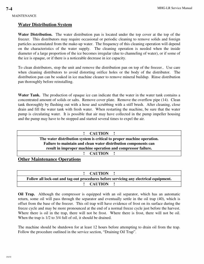
MHG-LR Service Manual
MAINTENANCE
1/6/10
7-4
Water Distribution System
Water Distribution. The water distribution pan is located under the top cover at the top of the
freezer. This distributors may require occasional or periodic cleaning to remove solids and foreign
particles accumulated from the make-up water. The frequency of this cleaning operation will depend
on the characteristics of the water supply. The cleaning operation is needed when the inside
diameter of a large proportion of the ice becomes irregular (due to channeling of water), or if some of
the ice is opaque, or if there is a noticeable decrease in ice capacity.
To clean distributors, stop the unit and remove the distribution pan on top of the freezer.. Use care
when cleaning distributors to avoid distorting orifice holes or the body of the distributor. The
distribution pan can be soaked in ice machine cleaner to remove mineral buildup. Rinse distribution
pan thoroughly before reinstalling.
Water Tank. The production of opaque ice can indicate that the water in the water tank contains a
concentrated amount of solids or salts. Remove cover plate. Remove the overflow pipe (14). Clean
tank thoroughly by flushing out with a hose and scrubbing with a stiff brush. After cleaning, close
drain and fill the water tank with fresh water. When restarting the machine, be sure that the water
pump is circulating water. It is possible that air may have collected in the pump impeller housing
and the pump may have to be stopped and started several times to expel the air.
! CAUTION !
The water distribution system is critical to proper machine operation.
Failure to maintain and clean water distribution components can
result in improper machine operation and compressor failure.
! CAUTION !
Other Maintenance Operations
! CAUTION !
Follow all lock-out and tag-out procedures before servicing any electrical equipment.
! CAUTION !
Oil Trap. Although the compressor is equipped with an oil separator, which has an automatic
return, some oil will pass through the separator and eventually settle in the oil trap (40), which is
offset from the base of the freezer. This oil trap will have evidence of frost on its surface during the
freeze cycle and may be more pronounced at the end of a normal freeze cycle just before the harvest.
Where there is oil in the trap, there will not be frost. Where there is frost, there will not be oil.
When the trap is 1/2 to 3/4 full of oil, it should be drained.
The machine should be shutdown for at least 12 hours before attempting to drain oil from the trap.
Follow the procedure outlined in the service section, “Draining Oil Trap”.

MHG-LR Service Manual
MAINTENANCE
1/6/10
7-5
! CAUTION !
Only qualified refrigeration service personnel familiar and
experienced in the handling and use of anhydrous ammonia (R717) should be
authorized to perform the “Draining Oil Trap” procedure.
! CAUTION !
Optional Maintenance Operations
The following sections outline some general guidelines for service of auxiliary equipment. Always
follow the instructions provided by equipment manufacturers when performing service operations or
scheduled maintenance.
Water Cooled Condenser Cleaning (optional). As water evaporates from a cooling tower, the
solid impurities remain and must be flushed from the system to prevent a scale build-up in the
condenser and cooling tower. This can be accomplished by a continuous bleed off valve located in
the pump discharge line. The valve should be adjusted to bleed off an equal amount of water that is
evaporated. If water hardness is very high, a higher bleed off rate or chemical treatment may be
required. Consult you local water treatment company for recommendations.
If after a period of time, scale has formed inside the tubes, mechanical cleaning may be necessary.
See “Servicing Section--Condenser”.
Cooling Tower/Evaporative Condenser (optional).
1. Bleed off valve. The bleed off valve should be checked monthly to assure that is not blocked and
that water is flowing as required. If the unit is controlled by a water treatment system, the bleed
off valve may not be required.
2. Strainer. The pan or sump strainer is located in the bottom of the sump at the suction connection
to the pump. The strainer should be inspected monthly and kept clean. Do not operate the unit
without the strainer in place.
3. Make-up water float valve. This valve should be checked monthly for proper operation and
adjustment. It should be adjusted to maintain a water level below the overflow and high enough
to prevent the pump from cavitating when the system is in operation.
4. Spray nozzles. The spray nozzles should be checked monthly to make sure none are restricted
and the spray pattern is complete and even.
5. Pump motor and fan motor. The motors should be checked and/or lubricated every six months
according to the motor manufacturer’s recommendations.
6. Fan bearings. The fan bearings should be lubricated every six months. Make sure the proper
grade of grease is used (normally conforms to NLCI-Grade 2) and it is best to use a hand grease
gun.
7. Fan belts. The fan belt tension should be checked weekly for the first two weeks of operation,
then monthly during continuous use.
The best tension for a V-belt is the lowest tension at which the belt will not slip under its full load.
Never use dressing on V-belts. Keep belts and grooves clean and free of oil, grease, and foreign
material. Clean with non-flammable, non-toxic degreasing agent or commercial detergent and water.

MHG-LR Service Manual
MAINTENANCE
1/6/10
7-6
! CAUTION !
Follow all lock-out and tag-out procedures before servicing any electrical equipment.
! CAUTION !
Maintenance Operation Start-Up Monthly Six Months Shutdown
Clean debris from unit X X X
Clean strainer and flush sump X X X
Check fan and pump rotation X
Clean spray nozzles X X
Check belt tension X X
Check for noise/vibration X X
Check/adjust make-up water valve X X
Check/adjust bleed rate X X
Check/lubricate fan bearings X X
Lubricate motor base adj. Screw X X X
Drain sump and piping X
TABLE 7-3
Cooling Tower Maintenance Schedule

MHG-LR Service Manual
MAINTENANCE
1/6/10
7-7
Compressor (optional). This section is only a guide; consult the compressor manual for
manufacturers recommended maintenance.
In starting and charging the unit, the oil sight glass should be continually checked to make sure an
adequate oil level is maintained. The oil level should be 1/4-3/4 of the sight glass. If the oil level
drops below 1/4 of the glass, add refrigeration oil as per the compressor manufacturer
recommendations. Never allow the oil level to be out of sight, above or below the sight glass when
the compressor is operating.
! CAUTION !
The crankcase heater should be energized for a minimum of
four hours and the oil temperature should be 100°°°°-110°°°°F
before attempting to start the compressor.
! CAUTION !
During operation, the specified net oil pressure should be maintained for proper lubrication and
operation of the cylinder unloader mechanism.
Mycom N&W Series net oil pressure: 17-28 psig
Vilter 450 Series net oil pressure: 35-50 psig
Note: Net oil pressure is calculated by subtracting the compressor suction pressure from the oil
pressure gage reading while the compressor is running.
Example: Oil pressure gage reading: 65 psig
Suction pressure gage reading: 40 psig
Net Oil Pressure: 25 psig
The compressor oil should be changed at close intervals during initial break-in operation and up to
the first 1000 hours (see Table 7-4 below).
Note: It is the owner’s responsibility to make sure normal maintenance is initiated to insure that the
compressor is not subjected to premature wear or failure due to neglect or lack of sufficient
maintenance and care.
Frequency Maintenance Operation
1st 2nd 3rd 4th Thereafter
Change oil 200 hr. 500 hr. 1500 hr. 4000 hr. Every 4000 hrs.
Clean suction strainer cloth 200 hr. 500 hr. Remove if clogging is minimal
TABLE 7-4
Compressor Maintenance
The above maintenance is only a guide. The compressor should be inspected anytime there is
unusual noise, damage is suspected or the oil becomes discolored. The oil should be changed any
time the compressor is opened. For specific recommendations and instructions, refer to the
particular compressor manufacturer’s manual.

MHG-LR Service Manual
TROUBLESHOOTING
1/6/10
8-1
8.Troubleshooting
! WARNING !
Only service personnel experienced and certified in refrigeration and qualified to work
with high voltage electrical equipment should be allowed to install or work
on this Turbo Refrigerating®
machine.
! WARNING !
! CAUTION !
Follow all lock-out and tag-out procedures before servicing any electrical equipment.
! CAUTION !
Note: Your machine’s electrical system has several built-in safety and overload protection features
to stop operation when a single component fails or there is a problem from an outside source
such a power supply. Make sure all auxiliary equipment is connected to incorporate safety
and overload circuits and protect all related equipment.
When the machine stops, it must be manually restarted by putting the Module in Auto and pushing
the MCS button on the Master Panel operator interface. The machine will restart in a harvest to clear
any ice from the freezer before beginning another cycle.
Always check the machine operation thoroughly after remedying the problem. Be sure to correct the
source or cause of the problem to prevent the problem from occurring again.
Symptom
Page
Machine stopped 8-2
Freeze-up due to extended freeze period 8-3
Freeze-up due to ice failing to discharge 8-3
Low ice capacity 8-4
Poor ice quality 8-5
High discharge pressure 8-5
Low discharge pressure 8-5
High suction pressure 8-6
Compressor running unloaded during freeze 8-6
Compressor oil pressure low 8-6
Compressor loosing oil excessively 8-6
Machine short cycles 8-7
High compressor discharge temperature 8-7
Suction line frosting to compressor 8-7
Contact your distributor first for technical service assistance about operation problems not covered in
this manual.
Also feel free to contact the factory for additional service (502) 635-3000.

MHG-LR Service Manual
TROUBLESHOOTING
1/6/10
8-2
Symptom: Machine Stopped
Possible Cause Possible Remedy
Power failure or interruption Check fused disconnect or circuit breaker supplying power to
the machine. If power has been off, make sure the crankcase
heater is energized and there is no liquid refrigerant in the
compressor crankcase prior to restarting the compressor. If ice
is on the freezer plates, initiate a manual harvest.
Control fuse (FU1) for control circuit tripped Check coils of relays, contactors, starters, solenoid valves, and
PLC for a ground. Repair or replace any defective part and
replace fuse. Make sure there is no liquid refrigerant in the
compressor crankcase prior to restarting the machine.
Compressor motor starter overload tripped Check for a loose connection on all motor starter and motor
terminals that could cause excessive amp draw. Reset overload
and restart the machine, check amperage, power supply, and
head pressure. (Check delay timer in part wind starts only).
Water pump, conveyor motor, overload tripped Check for loose connection on all terminals that could cause
excessive amp draw. Reset the overload and manually run that
particular motor to check actual voltage and amperage against
motor rating.
Freezer water pump motor overload (WP) tripped Check for loose terminal connections and/or blown fuse, reset
the overload and restart by pushing the start push button
(PB1). Machine will start in a harvest. Check voltage and
amperage against motor rating during freeze. Confirm proper
rotation.
Screw Conveyor 1 or Screw Conveyor 2 (Take Away
Conveyors)
In some cases the motor starter for the conveyors may be
supplied by Vogt. Check for loose terminal connections
and/or blown fuse. Clear all ice that may have jammed the
conveyor. Reset the overload and test by pushing the “Purge”
push button on the operator interface “Screw Purge” screen.
Check voltage and amps against motor rating. If tripping
repeats but ice is not jammed, check the conveyor for worn
bearings/liners, and reducer motor for defect or single phasing.
Bin level control open
The Bin Level Switch is installed in your ice storage bin and
wires into the Master Panel. Adjust or replace control as
required. If bin level control is not used, make sure jumper
wire from #L1 to #20 is installed at the terminal block.
High/Low pressure safety switch tripped (optional) If the machine stops by low pressure cutout, the switch will
reset automatically when the pressure rises to the “cut-in”
setting. Check thaw gas valve (18) to make sure it opens
during harvest time. Check Liquid feed valve (25) to make
sure it is feeding during a freeze.
If the machine stops by high pressure cutout, the switch will
have to be manually reset after the pressure drops below the
“cut-in” setting. Check the head pressure during the next
freeze cycle.
Low oil pressure tripped (OPS) located on compressor Manually reset the switch after the switch heater cools. Check
the crankcase oil level (1/4-3/4 full). Add oil if below 1/4
glass before attempting to restart the machine.
Restart the machine and check net oil pressure (net oil pressure
= oil pump line pressure minus crankcase suction pressure).
Net oil pressure range: Mycom= 17-28 psig Vilter= 35-50 psig
Defective control panel component such as ETH1, LVR, SVR,
PLC, WP
Check for open circuit. Refer to FIGURES 6-1 and 6-2,
Control Panel to identify parts. Check for loose wires.
Replace defective part, restart machine, check power supply,
and current draw.
Main Three Phase power fused disconnect (option) for
Module(s) blown.
Check for loose connection on all terminals, replace fuse and
check amp draw against fuse rating. Check voltage and current
unbalance, Section 3. Replace fuse if blown.

MHG-LR Service Manual
TROUBLESHOOTING
1/6/10
8-3
Symptom: Freeze-up due to extended freeze period
Possible Cause Possible Remedy
Refrigeration timer set to long Adjust timer setpoint in the settings screen.
Water tank drain valve, make-up water float valve or flushing
valve opened too far
Close, repair, or replace valve as needed. The float valve
should be adjusted low enough that water should not run out
the tank overflow during the freeze cycle.
Compressor running unloaded If the compressor is running unloaded, the motor amp draw
will only be 60%-70% of the normal amp draw of a loaded
compressor.
Refer to the compressor manual for normal oil pressure needed
to load the compressor cylinders and any further procedures to
check the mechanical function of the unloader mechanism.
Symptom: Freeze-up due to ice failing to discharge
Possible Cause Possible Remedy
Refrigeration timer set to long Adjust timer setpoint in the settings screen.
Defrost time too short Adjust defrost timer in the settings screen to allow all ice to
clear the plates ice discharge opening with at least 15 seconds
to spare. See pressure regulating valve adjustment.
Defrost pressure to low The defrost gas regulator should be adjusted to increase the
pressure in the plates to 80-90 psi during a harvest. Isolate and
repair or replace the valve as needed.
Insufficient heat for defrost due to low condensing pressure The head pressure should be maintained form 175-190 psi
(maximum 200) usually by a water regulating valve or fan
cycling switch. Check to make sure these controls are working
properly. Cold prevailing wind can also be a factor.
Insufficient heat due to non-condensables (usually air) in the
system
If non-condensables are present with the refrigerant, the
saturated temperature will not relate to the pressure reading at
the receiver and the refrigerant will be cooler, although
pressure will be high. Air can be purged from the system by
following the procedure in the Section 9, “Purging Non-
Condensables”.
Auger does not turn, backing ice up to freezer Check gear reducer and drive motor for proper operation and
alignment. Check for broken belts or sheared shaft key.
Replace defective parts.
Excessive concentration of solids in the water tank usually
indicated by a build-up of mineral deposit on the freezer plates.
Perform a cleaning procedure as well as removing the freezer
cover and cleaning the water distributors. Make sure the
flushing valve (27) is functioning and the tank overflow piping
is not restricted.
Compressor not running unloaded during thaw cycle.
(for single section Module with dedicated high side only)
Check compressor motor Amp draw. During the thaw cycle,
the compressor motor Amp draw should be 60 - 70% of normal
amp draw during the freeze cycle. Check compressor unloader
solenoid coil to make sure it is energized and the valve is
opening during the thaw cycle.
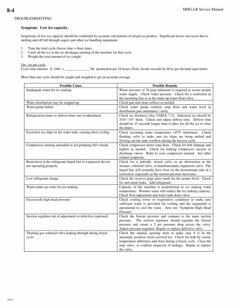
MHG-LR Service Manual
TROUBLESHOOTING
1/6/10
8-4
Symptom: Low ice capacity.
Suspicions of low ice capacity should be confirmed by accurate calculations of actual ice product. Significant losses can occur due to
melting and off fall through augers and other ice handling equipment.
1. Time the total cycle (freeze time + thaw time).
2. Catch all the ice at the ice discharge opening of the machine for that cycle.
3. Weight the total amount of ice caught.
Lbs. ice per cycle
Cycle time minutes X 1440 = ______________ lbs. production per 24 hours (Note: divide seconds by 60 to get decimal equivalent)
More than one cycle should be caught and weighed to get an accurate average.
Possible Cause Possible Remedy
Inadequate water for ice making Water pressure of 30 psig minimum is required to assure proper
water supply. Check water pressure. Check for a restriction in
the incoming line or at the make-up water float valve.
Water distribution may be stopped up Check pan and clean orifices as needed.
Water pump failure Check water pump rotation, amp draw and water level in
distribution pan (minimum 1 inch).
Refrigeration timer or defrost timer out of adjustment Check ice thickness (See TABLE 7-2). Industrial ice should be
3/16”-1/4” thick. Check and adjust defrost time. Defrost time
should be 15 seconds longer than it takes for all the ice to clear
the plates.
Excessive ice chips in the water tank, causing short cycling Check incoming water temperature (45°F minimum). Check
flushing valve to make sure ice chips are being melted and
flowing out the tank overflow during the harvest cycle.
Compressor running unloaded or not pumping full volume Check compressor motor amp draw. Check for belt slippage and
tighten as needed. Check for leaking compressor suction or
discharge valves. Refer to your compressor manual. See other
related symptoms.
Restriction in the refrigerant liquid line or expansion device
not operating properly
Check for a partially closed valve or an obstruction at the
strainer, solenoid valve, or hand/automatic expansion valve. The
liquid line will normally have frost on the downstream side of a
restriction, especially as the suction pressure decreases.
Low refrigerant charge Check the receiver gage glass mark for the proper level. Check
for and repair leaks. Add refrigerant.
Warm make-up water for ice making Capacity of the machine is proportional to ice making water
temperature. Warmer water will reduce the ice making capacity.
Check float adjustment and water tank drain valve.
Excessively high head pressure Check cooling tower or evaporative condenser to make sure
sufficient water is provided for cooling and the equipment is
operational to cool the water. Also see “Symptom High Head
Pressure”.
Suction regulator out of adjustment or defective (optional) Check the freezer pressure and compare to the main suction
pressure. The suction regulator should regulate the freezer
pressure and create a 2 psi pressure drop across the valve.
Adjust pressure regulator. Repair or replace defective valve.
Thawing gas solenoid valve leaking through during freeze
cycle
Check the manual opening stem to make sure it is in the
automatic position (stem screwed in). Check for leak by sound,
temperature difference and frost during a freeze cycle. Close the
stop valve to confirm suspicion of leakage. Repair or replace
the valve.

MHG-LR Service Manual
TROUBLESHOOTING
1/6/10
8-5
Symptom: Poor ice quality
Possible Cause Possible Remedy
Excessive concentration of solids in the water tank usually
indicated by a build-up of mineral deposit on the sides and
bottom of the tank and opaque ice production. Also, water
distributors restricted.
Perform a cleaning procedure as well as removing the freezer
cover and cleaning the water distributors. Make sure the
flushing valve (13) is functioning and the tank overflow piping
is not restricted.
Insufficient water supply indicated by a low level in the tank Check water pressure, 30 psig is recommended minimum.
Check for a water line restriction, partially closed valve, or
defective make-up water float valve. Make sure the water tank
drain is closed.
Water pump rotation wrong direction Check rotation in relation with arrow on pump housing and
reverse two wires at the motor if necessary.
Low refrigerant charge. Check refrigerant level mark on the receiver and on the painted
portion of the gage glass guard. Be sure to keep the gage glass
cocks closed when finished checking the level.
Suction Pressure to low Adjust suction regulator valve
Restriction in liquid line, starving evaporator Check for closed valve, defective butterfly valve, or strainer
restricted. The liquid line will normally have frost on the
down-stream side of a restriction, especially as the suction
pressure decreases.
Symptom: High discharge pressure (check gage accuracy)
Possible Cause Possible Remedy
Insufficient water flow through the cooling tower or condenser Check the condenser water pump to make sure it is pumping
enough water. Check sump strainer screen and clean. Check
condenser pump direction of rotation.
Fan control out of adjustment Check adjustment. Replace if defective.
Non-condensable in system. If non-condensables are present with the refrigerant, the
saturated temperature will not relate to the pressure reading at
the receiver. The refrigerant will be cooler, although the
pressure will be high. Air can be purged from the system by
following instructions in Section 9, “Purging Non-
Condensables”.
Cooling tower or evaporative condenser requires maintenance Check fan motor and fan belts for proper operation and
tension. Check spray nozzles, tubes, sump, and sump screen,
for accumulation of mineral deposit and clean as required.
Check tower blowdown and chemical treatment if applicable.
Dirty condenser tubes Visually inspect the condenser tubes to see if there is any
build-up of mineral deposits which would reduce the cooling
effect of the tubes and water. Clean chemically or
mechanically as applicable.
Symptom: Low discharge pressure (check gage accuracy)
Possible Cause Possible Remedy
Fan cycling switch out of adjustment or defective Check adjustment. Replace if defective.
Compressor running unloaded or not pumping efficiently Check compressor motor amp. If the compressor is running
unloaded, the amperage will only be approximately 60% of
normal amp draw (FLA). Refer to the compressor manual.
Ambient temperature low and prevailing winds blowing
through tower
Shield tower from prevailing winds to prevent excessive
cooling. Install an indoor sump.
Too much cold water circulating through condenser Install a water regulating valve in the water line form the
condenser and control flow by receiver pressure.
Thaw gas valve (18) leaking through Make sure manual opening stem is in the automatic (screwed
in) position. Repair or replace defective parts.
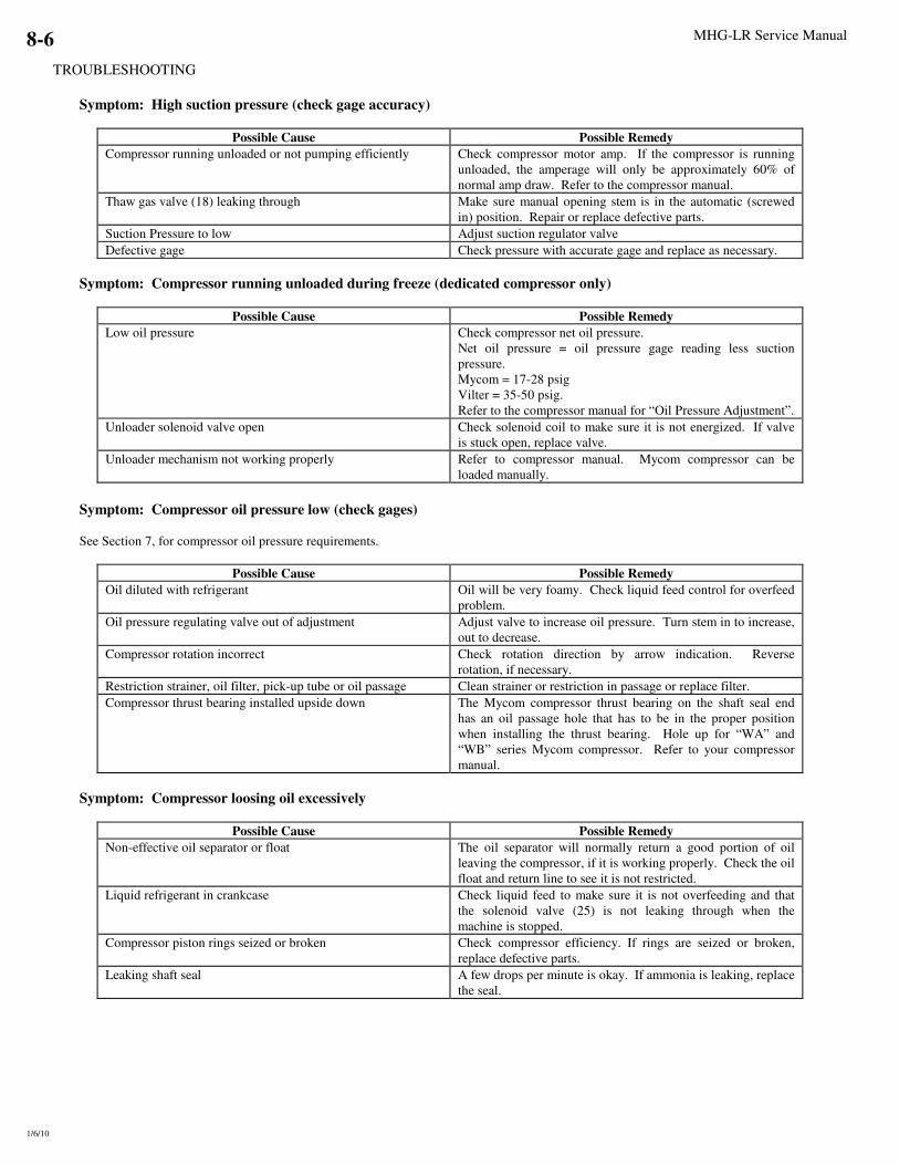
MHG-LR Service Manual
TROUBLESHOOTING
1/6/10
8-6
Symptom: High suction pressure (check gage accuracy)
Possible Cause Possible Remedy
Compressor running unloaded or not pumping efficiently Check compressor motor amp. If the compressor is running
unloaded, the amperage will only be approximately 60% of
normal amp draw. Refer to the compressor manual.
Thaw gas valve (18) leaking through Make sure manual opening stem is in the automatic (screwed
in) position. Repair or replace defective parts.
Suction Pressure to low Adjust suction regulator valve
Defective gage Check pressure with accurate gage and replace as necessary.
Symptom: Compressor running unloaded during freeze (dedicated compressor only)
Possible Cause Possible Remedy
Low oil pressure Check compressor net oil pressure.
Net oil pressure = oil pressure gage reading less suction
pressure.
Mycom = 17-28 psig
Vilter = 35-50 psig.
Refer to the compressor manual for “Oil Pressure Adjustment”.
Unloader solenoid valve open Check solenoid coil to make sure it is not energized. If valve
is stuck open, replace valve.
Unloader mechanism not working properly Refer to compressor manual. Mycom compressor can be
loaded manually.
Symptom: Compressor oil pressure low (check gages)
See Section 7, for compressor oil pressure requirements.
Possible Cause Possible Remedy
Oil diluted with refrigerant Oil will be very foamy. Check liquid feed control for overfeed
problem.
Oil pressure regulating valve out of adjustment Adjust valve to increase oil pressure. Turn stem in to increase,
out to decrease.
Compressor rotation incorrect Check rotation direction by arrow indication. Reverse
rotation, if necessary.
Restriction strainer, oil filter, pick-up tube or oil passage Clean strainer or restriction in passage or replace filter.
Compressor thrust bearing installed upside down The Mycom compressor thrust bearing on the shaft seal end
has an oil passage hole that has to be in the proper position
when installing the thrust bearing. Hole up for “WA” and
“WB” series Mycom compressor. Refer to your compressor
manual.
Symptom: Compressor loosing oil excessively
Possible Cause Possible Remedy
Non-effective oil separator or float The oil separator will normally return a good portion of oil
leaving the compressor, if it is working properly. Check the oil
float and return line to see it is not restricted.
Liquid refrigerant in crankcase Check liquid feed to make sure it is not overfeeding and that
the solenoid valve (25) is not leaking through when the
machine is stopped.
Compressor piston rings seized or broken Check compressor efficiency. If rings are seized or broken,
replace defective parts.
Leaking shaft seal A few drops per minute is okay. If ammonia is leaking, replace
the seal.

MHG-LR Service Manual
TROUBLESHOOTING
1/6/10
8-7
Symptom: High compressor discharge temperature
Possible Cause Possible Remedy
High head pressure Check gage accuracy and “High discharge pressure”.
Defective suction or discharge valves Feel the compressor heads for hot spots or one head running
hot. Replace worn or leaking valves.
Restriction in the discharge gas line Check all hand and check valves to make sure they are fully
opened and not stuck. Repair or replace as needed.
Internal relief valve leaking Check the compressor manual to see if your compressor is so
equipped. Replace accordingly.
Symptom: Suction line frosting to compressor
Possible Cause Possible Remedy
Liquid refrigerant overfeed Check float switch to make sure it is functioning properly.
Replace if defective. Check solenoid valve (25) to make sure it
is not leaking through. Repair or replace if defective.
Refrigerant contaminated with water Test refrigerant or oil for water contamination. Completely
pump the freezer out (pumpdown) and blow excess water out
through the oil trap drain valve. Refer to Service, Section 9
“Removing Excess Water”.

MHG-LR Service Manual
TROUBLESHOOTING
1/6/10
8-8

MHG-LR Service Manual
SERVICE OPERATIONS
1/6/10
9-1
9. Service Operations
Total Cycle Time. The freezing time period for the production of ice on the plates is controlled by
the Total Cycle Time. This setting is located in the Settings Menu via the Icemaker option on the
operator interface. This controls how often defrost occurs on a specific Module regardless of how
many Modules may be connected. The timer was set at the factory to a default of 15 minutes. The
cycle time can be adjusted to compensate for water temperature and refrigeration system conditions.
Do not make adjustments until several ice-discharging cycles have been made.
Standard Defrost Time. The defrost timer governs the ice harvesting period. This setting is
located in the Settings Menu via the Icemaker option on the operator interface. This timer is set prior
to shipment for approximately a two-minute period. Set the defrost time for at least 30 seconds
longer than the time required to harvest the entire discharge of ice. Check defrost time after each
adjustment.
Dry Time. The Dry Time is the amount of time prior to defrost that stops the water pump to allow
the ice to sub-cool and dry prior to the harvest cycle. This is an optional setting that works only
when the “Water Pump On/Off during Defrost” is set to “Off”. If this option is selected, a longer
harvest will result, make sure the harvest time is adequate if this option is selected.
Liquid Shut Off. This setting controls the time period before defrost that closes the liquid solenoid.
This is used to improve harvest time.
Manual Defrost Time. This setting controls the length of a user initiated manual defrost. This
setting is changed via the operator interface. Manual Defrost can be initiated via the interface or the
mode selection button on the Module.
Extended Defrost Time. As an added feature of your machine, you have an extended defrost time
setting that will extend defrost under either of two conditions: 1) if the Defrost Pressure Switch
detects a low pressure condition, this time is added to the Standard Defrost Time, 2) the second
condition is listed below.
Defrost Extend Count. Every time defrost occurs on a module, a counter is incremented. When
that counter reaches the set point of this setting, the defrost is extended by the setting of the Extended
Defrost Setting.
Conveyor Timer. This setting controls how long the screw conveyor runs after defrost ends.
Make-up Water Float Valve (37A). The make-up float valve maintains the proper level in the
water tank for ice making. The valve should be set to maintain a water level in the water tank during
the freezing period so that there will be a quantity of blowdown only during the thaw mode. The
water level during the freeze mode should always be below the overflow piping to prevent excessive
waste of cold water, resulting in loss of ice capacity.
If it should become necessary to clean the float valve, close the stop valve in the make-up water line
to the machine and remove the float valve. After the valve has been cleaned and reinstalled, check to
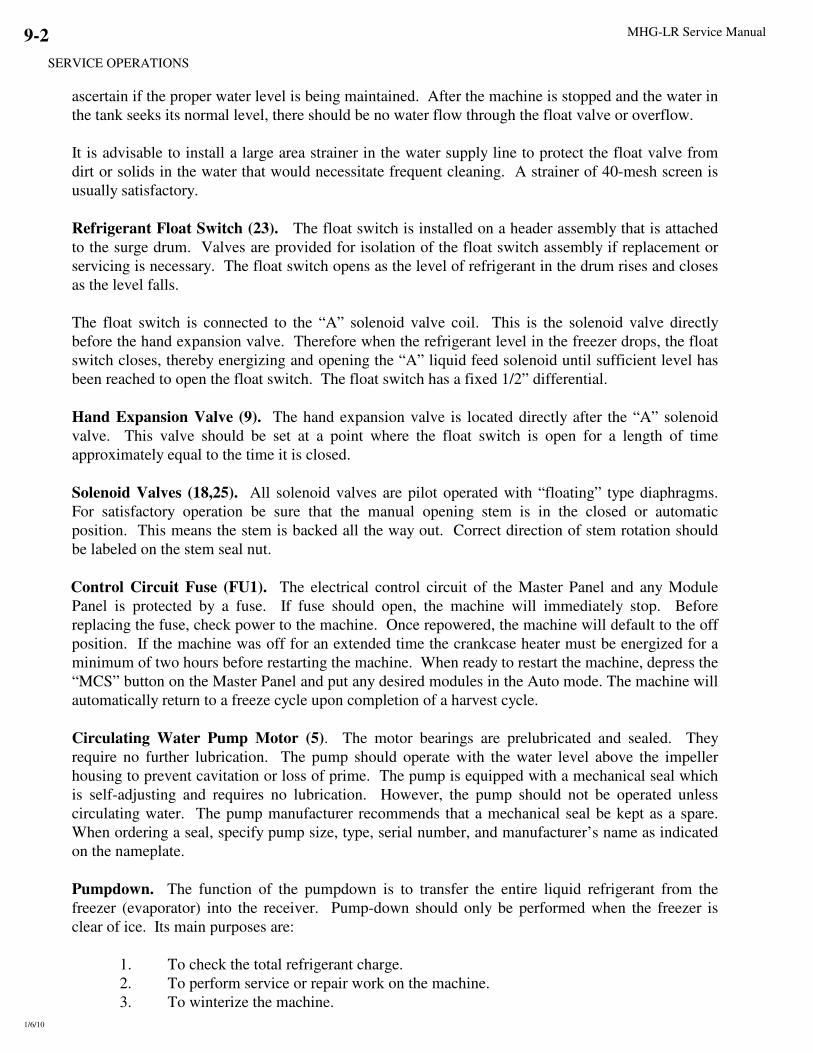
MHG-LR Service Manual
SERVICE OPERATIONS
1/6/10
9-2
ascertain if the proper water level is being maintained. After the machine is stopped and the water in
the tank seeks its normal level, there should be no water flow through the float valve or overflow.
It is advisable to install a large area strainer in the water supply line to protect the float valve from
dirt or solids in the water that would necessitate frequent cleaning. A strainer of 40-mesh screen is
usually satisfactory.
Refrigerant Float Switch (23). The float switch is installed on a header assembly that is attached
to the surge drum. Valves are provided for isolation of the float switch assembly if replacement or
servicing is necessary. The float switch opens as the level of refrigerant in the drum rises and closes
as the level falls.
The float switch is connected to the “A” solenoid valve coil. This is the solenoid valve directly
before the hand expansion valve. Therefore when the refrigerant level in the freezer drops, the float
switch closes, thereby energizing and opening the “A” liquid feed solenoid until sufficient level has
been reached to open the float switch. The float switch has a fixed 1/2” differential.
Hand Expansion Valve (9). The hand expansion valve is located directly after the “A” solenoid
valve. This valve should be set at a point where the float switch is open for a length of time
approximately equal to the time it is closed.
Solenoid Valves (18,25). All solenoid valves are pilot operated with “floating” type diaphragms.
For satisfactory operation be sure that the manual opening stem is in the closed or automatic
position. This means the stem is backed all the way out. Correct direction of stem rotation should
be labeled on the stem seal nut.
Control Circuit Fuse (FU1). The electrical control circuit of the Master Panel and any Module
Panel is protected by a fuse. If fuse should open, the machine will immediately stop. Before
replacing the fuse, check power to the machine. Once repowered, the machine will default to the off
position. If the machine was off for an extended time the crankcase heater must be energized for a
minimum of two hours before restarting the machine. When ready to restart the machine, depress the
“MCS” button on the Master Panel and put any desired modules in the Auto mode. The machine will
automatically return to a freeze cycle upon completion of a harvest cycle.
Circulating Water Pump Motor (5). The motor bearings are prelubricated and sealed. They
require no further lubrication. The pump should operate with the water level above the impeller
housing to prevent cavitation or loss of prime. The pump is equipped with a mechanical seal which
is self-adjusting and requires no lubrication. However, the pump should not be operated unless
circulating water. The pump manufacturer recommends that a mechanical seal be kept as a spare.
When ordering a seal, specify pump size, type, serial number, and manufacturer’s name as indicated
on the nameplate.
Pumpdown. The function of the pumpdown is to transfer the entire liquid refrigerant from the
freezer (evaporator) into the receiver. Pump-down should only be performed when the freezer is
clear of ice. Its main purposes are:
1. To check the total refrigerant charge.
2. To perform service or repair work on the machine.
3. To winterize the machine.

MHG-LR Service Manual
SERVICE OPERATIONS
1/6/10
9-3
4. To prepare the machine for disconnecting and moving.
5. Before cleaning
Pumpdown Procedure To perform a pumpdown, follow this procedure:
1. With the machine running, close the liquid feed stop valve nearest the receiver
2. Put the water pumps in manual operation.
3. Open the water tank drain valve partially to allow a continuous flow of warm make-up water into
the water tank and still maintain a good level in the tank. An auxiliary supply of warm water (not
to exceed 100°F) may be used if available. Warmer water affords a more complete pumpdown.
4. Allow the machine to operate and eventually it will shutdown on low pressure
5. When the suction pressure increases to 70 psig or higher, start the compressor and allow the
machine to stop automatically by the low pressure switch at approximately 15 psig. (Lower
pressure can be obtained by jumping out the pressure switch.) Remove all power from the
machine before opening the control panel cover. With the pressure switch jumped out, the
machine can be manually started and stopped. Do not operate the machine below 2 psig.
6. When the desired pumpdown is obtained, close the thawing gas stop valve, and the compressor
discharge line stop valve. Other valves may also be closed to isolate a particular area that may
require attention.
7. To perform a total pumpdown, it may be necessary to apply heat directly to the oil trap in order to
boil off the liquid ammonia and oil mixture.
Removal of Ammonia Refrigerant from the Machine. Liquid ammonia can be removed from the
machine through the receiver drain valve. Refer to Sections 1, 2 and Appendix A for special
warnings and instructions regarding the handling of ammonia. Make sure you are familiar with and
technically qualified to handle anhydrous-ammonia refrigerant.
! WARNING !
Approved recovery equipment, hoses, gages, and refrigerant containers must be
used to comply with all local and federal EPA regulations.
! WARNING !
! WARNING !
Follow these instructions carefully.
Severe personal injury can result from improper
discharge of refrigerant.
! WARNING !
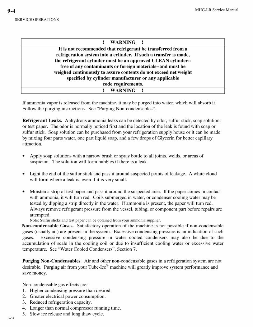
MHG-LR Service Manual
SERVICE OPERATIONS
1/6/10
9-4
! WARNING !
It is not recommended that refrigerant be transferred from a
refrigeration system into a cylinder. If such a transfer is made,
the refrigerant cylinder must be an approved CLEAN cylinder--
free of any contaminants or foreign materials--and must be
weighed continuously to assure contents do not exceed net weight
specified by cylinder manufacturer or any applicable
code requirements.
! WARNING !
If ammonia vapor is released from the machine, it may be purged into water, which will absorb it.
Follow the purging instructions. See “Purging Non-condensables”.
Refrigerant Leaks. Anhydrous ammonia leaks can be detected by odor, sulfur stick, soap solution,
or test paper. The odor is normally noticed first and the location of the leak is found with soap or
sulfur stick. Soap solution can be purchased from your refrigeration supply house or it can be made
by mixing four parts water, one part liquid soap, and a few drops of Glycerin for better capillary
attraction.
• Apply soap solutions with a narrow brush or spray bottle to all joints, welds, or areas of
suspicion. The solution will form bubbles if there is a leak.
• Light the end of the sulfur stick and pass it around suspected points of leakage. A white cloud
will form where a leak is, even if it is very small.
• Moisten a strip of test paper and pass it around the suspected area. If the paper comes in contact
with ammonia, it will turn red. Coils submerged in water, or condenser cooling water may be
tested by dipping a strip directly in the water. If ammonia is present, the paper will turn red.
Always remove refrigerant pressure from the vessel, tubing, or component part before repairs are
attempted. Note: Sulfur sticks and test paper can be obtained from your ammonia supplier.
Non-condensable Gases. Satisfactory operation of the machine is not possible if non-condensable
gases (usually air) are present in the system. Excessive condensing pressure is an indication of such
gases. Excessive condensing pressure in water cooled condensers may also be due to the
accumulation of scale in the cooling coil or due to insufficient cooling water or excessive water
temperature. See “Water Cooled Condensers”, Section 7.
Purging Non-Condensables. Air and other non-condensable gases in a refrigeration system are not
desirable. Purging air from your Tube-Ice
machine will greatly improve system performance and
save money.
Non-condensable gas effects are:
1. Higher condensing pressure than desired.
2. Greater electrical power consumption.
3. Reduced refrigeration capacity.
4. Longer than normal compressor running time.
5. Slow ice release and long thaw cycle.

MHG-LR Service Manual
SERVICE OPERATIONS
1/6/10
9-5
Air collects mostly in high pressure condensers, receivers, and other high-pressure components. It
collects mostly in the coolest, lowest-velocity area of these components. Evaporative condensers
usually have purge points at the top of the outlet header of each circuit. Receivers usually have a
purge point at the top, away from the inlet, where it is coolest and the gas velocity is the lowest.
The freezer can be purged through the valve at the top of the suction line, but should be done only
during the thaw cycle or after the system has been idle at least two hours.
Purging Procedure Follow this procedure when purging:
1. Connect a suitable hose to the purge valve and place the other end in water.
2. Open (slightly) the purge valve and allow air to escape.
3. Air will appear as bubbles in the water rising to the surface.
4. The larger the bubbles, the more air is escaping.
5. DO NOT leave the purge hose unattended.
6. When air bubbles are reduced to a minute size (smaller than 1/16), it can be considered that most
of the air has escaped and purging can be ceased at this point.
7. Additional purging can be done at other purge points.
8. When purging is completed, close the valve, disconnect the hose, and install a plug in the purge
valve.
Draining the Oil Trap. After many hours of operation, the oil which escapes the oil separator will
pass through the receiver and to the freezer where it will settle in the oil trap (22). Indication of oil
in the trap will be evident by the frost line. At the end of a freeze cycle, frost (or ice) will form on
that part of the oil trap where oil is not present. When frost is seen only on the top 1/4 to 1/2 of the
oil trap, the oil trap should be drained. Do not allow the oil trap to fill completely with oil, or it will
cause loss of ice production and possible refrigerant floodback to the compressor.
Oil Trap Draining Procedure
1. Stop the machine and wait 12 hours or more.
2. Attach a suitable hose to the oil trap drain valve #61. Make sure there are no kinks or restrictions
in the hose.
3. Open the valve slightly until oil begins to drain.
4. Continually observe the oil flow, being ready to close the valve quickly.

MHG-LR Service Manual
SERVICE OPERATIONS
1/6/10
9-6
! DANGER !
Do not leave the oil trap drain valve opened or unattended--severe injury may result
! DANGER !
5. When a small amount of liquid ammonia begins to spew out, immediately close the valve.
6. Remove the hose and install a plug in the valve. DO NOT attempt to reuse any oil taken from
the system unless it is properly reclaimed and meets the proper specifications.
Removing Excess Water from Ammonia
If excessive water is in the ammonia, it will cause frost on the suction line to the compressor, and
dilution of the oil. This condition should not go uncorrected and the water needs to be removed.
Water Removal Procedure
1. Perform a total pumpdown of the freezer. See “Pumpdown” page 9-4.
2. A total pumpdown is accomplished when there is no frost or ice on the freezer or oil trap and the
freezer pressure is below that pressure relative to the surrounding temperature. Refer to the
Temperature-Pressure chart for ammonia.
3. With the freezer pressure below 25 PSIG, attach a hose to the oil trap drain valve and extend the
other end into a container (5 gallon bucket, etc.).
4. Open the drain valve a little and drain out the oil and water that is present.
5. Continue to drain oil/water, and purge the freezer and compressor to 0 PSIG.
6. Close the compressor discharge stop valve and the oil return valve. Make sure the power is
disconnected and locked-out.
7. Drain the compressor oil, remove the compressor side cover and clean the inside of all oil and
foreign matter, and reinstall the side cover.
8. Connect a vacuum pump, or pumps to the freezer and compressor, and evacuate them to 2000
microns or below while maintaining 60°F (10°c) or higher room temperature. A 5 CFM or larger
vacuum pump is best.
9. During evacuation, add new oil to the compressor. Also purge the receiver for non-
condensables.
10. After evacuation, break the vacuum by manually opening the liquid line solenoid valve and
gradually opening the liquid line stop valve (24) or at the receiver, letting liquid ammonia enter
the freezer and raise the pressure.

MHG-LR Service Manual
SERVICE OPERATIONS
1/6/10
9-7
11. When the freezer (suction) pressure is up to at least 60 PSI, manually close the liquid line
solenoid valve and restore power to the machine.
12. Open the compressor discharge valve, oil return valve, and all other valves that should be opened
for normal operation.
13. When the receiver liquid level is near its normal operating level or the pressures are near equal
and the compressor crankcase has warmed, the compressor can be started and ice production
resumed.
14. After several cycles, check the system for symptoms of excessive water, and if necessary, repeat
the pumpdown and evacuation procedure.
Note: whenever excessive water is present in the system, the source should be identified and
corrections made prior to further operation.

Appendix A

Material Safety Data Sheet # 4001 LAROCHE INDUSTRIES INC.
2/15/96
SECTION 1: CHEMICAL PRODUCT & COMPANY IDENTIFICATION
CHEMICAL NAME: Anhydrous Ammonia TRADE NAMES/SYNONYMS Ammonia
PRODUCT CODE: 5B81-83
MANUFACTURER AND/OR DISTRIBUTOR: EMERGENCY TELEPHONE NUMBERS:
LaRoche Industries Inc. Transportation (CHEMTREC): (800) 424-9300
1100 Johnson Ferry Rd., NE Environmental/Health/Safety: (800) 528-4963
Atlanta, Ga. 30342 Customer Service: (800) 491-7987
SECTION 2: COMPOSITION/INFORMATION ON INGREDIENTS
CHEMICAL FORMULA % BY WEIGHT CAS OSHA PEL NIOSH REL / ACGIH TLV IDLH
C-grade P-grade
Ammonia NH3 99.5 99.995 7664-41-7 50 ppm (TWA) 25 ppm (TWA) 35 ppm (STEL) 300 ppm
Water H2O 0.4 33 ppm 7732-18-5 None None None
Oil ----- 0.1 2 ppm ------------ None None None
SECTION 3: HAZARDS INDENTIFICATION
EMERGENCY OVERVIEW: 1) Colorless gas or compressed liquid with extremely pungent odor 2) Liquid ammonia reacts violently with
water. Vapor cloud is produced 3) Avoid contact with liquid and vapor 4) Stay upwind and use water spray to absorb vapor
5) Not flammable under conditions likely to be encountered outdoors 6) Stop discharge if possible
POTENTIAL HEALTH EFFECTS:
ROUTES OF ENTRY: Inhalation, Skin Contact, Eye Contact, Ingestion TARGET ORGANS: Eyes, skin and respiratory system
EYE CONTACT: Exposure to liquid or high concentrations of vapor can cause painful, instant and possibly irreversible damage to
tissue such as the conjunctiva, cornea and lens.
SKIN CONTACT: Prolonged contact with high concentrations can cause painful tissue damage, frostbite and serious chemical burns.
INHALATION: Depending on exposure concentration and durationís, effects can vary from none or only mild irritation, to obstruction
of breathing from laryngeal and bronchial spasm, to edema and severe damage of the mucous membranes of the respiratory tract with
possible fatal results. Latent edema and residual reduction in pulmonary function may occur.
INGESTION: Tissue damage, chemical burns, nausea and vomiting can occur. Ammonia is a gas under normal atmospheric conditions
and ingestion is unlikely.
CARCINOGENICITY: NTP? No IARC? No OSHA? No
SECTION 4: FIRST AID MEASURES
EYE CONTACT: Flush with large amount of water for at least 15 minutes then immediately seek medical aid.
SKIN CONTACT: Immediately flush with large quantities of water for at least 15 minutes while removing clothing. Clothing frozen to the
skin should be thawed with water before removal. Seek immediate medical aid.
INHALATION: Remove from exposure. If breathing has stopped or is difficult, administer artificial respiration or oxygen as needed.
Seek immediate medical aid.
INGESTION: Do not induce vomiting. Have the victim drink large quantities of water if conscious. Immediately seek medical aid. Never
give anything by mouth to an unconscious person.
SECTION 5: FIRE FIGHTING MEASURES
FLASH POINT(method used): Not Applicable FLAMMABLE LIMITS: 16-25% in air
EXTINGUISHING MEDIA: With a source of ignition, ammonia will burn in the range of 16-25% in air. Stop flow of gas or liquid.
SPECIAL FIRE FIGHTING PROCEDURES: Move containers from fire zone if possible; if not, use water to cool fire exposed
containers. Use water spray to control vapors. Do not put water directly on liquid ammonia. Personnel must be equipped with
appropriate protective clothing and respiratory protection.
NFPA HAZARD CLASSIFICATION: Health: 3 Flammability: 1 Reactivity: 0 (least-0 ↔↔↔↔ 4-highest)
SECTION 6: ACCIDENTAL RELEASE MEASURES
Release of 100 lbs. or more of ammonia within 24 hours must be immediately (within minutes) reported to the National Response Center at
1-800-424-8802, as well as appropriate local and state agencies. Suggested Local Action: Stop leak if feasible. Avoid breathing ammonia.
Evacuate personnel not equipped with protective clothing and equipment. Use copious amounts of water spray or fog to absorb ammonia
vapor. DO NOT put water on liquid ammonia. Contain run-off to prevent ammonia from entering a stream, lake, sewer, or ditch. Any
release of this material, during the course of loading, transporting, unloading or temporary storage, must be reported to U.S. D.O.T. as
required by CFR 171.15 and 171.16.
SECTION 7: HANDLING AND STORAGE
Refer to the ANSI K61.1 standard for storage and handling information. Protect containers from physical damage and temperatures
exceeding 120∞F. Use only approved storage systems. Zinc, copper, silver, cadmium and their alloys must not be used in ammonia systems
since they can be rapidly corroded by it. Avoid hydrostatic pressure, which can cause equipment rupture, by adhering to proper filling
procedures and the use of hydrostatic pressure relief valves where appropriate.

SECTION 8: EXPOSURE CONTROLS/PERSONAL PROTECTION
RESPIRATORY PROTECTION: Respiratory protection approved by NIOSH/MSHA for ammonia must be used when
exposure limits are exceeded. Whether a chemical cartridge respirator or a self-contained breathing apparatus is sufficient for effective
respiratory protection depends on the type and magnitude of exposure.
EYE PROTECTION: Chemical splash goggles, approved for use with ammonia, must be worn to prevent eye contact with liquid or vapor.
A face shield should be used for increased protection from contact with liquid.
VENTILATION: Local positive pressure and/or exhaust ventilation should be used to reduce vapor concentrations in confined spaces.
Ammonia vapor, being lighter than air, can be expected to dissipate to the upper atmosphere. Ammonia concentrations may also be
reduced by the use of an appropriate absorbent or reactant material.
OTHER EQUIPMENT: Emergency eye wash stations and deluge safety showers must be available in the work area. Post a list of
emergency response contacts and telephone numbers.
SECTION 9: PHYSICAL AND CHEMICAL PROPERTIES
Boiling Point: -28.1°F Vapor Pressure: 4802.9 mm Hg @60°F Vapor Density: 0.60 @ 32°F (Air=1)
Solubility In Water: High Percent Volatile By Volume: 100% pH: Approx. 11.6 for 1 N Soln. in water
Melting Point: -107.9°F Specific Gravity: 0.62 @ 60°F (water=1) Appearance: Colorless (pungent) gas
SECTION 10: STABILITY AND REACTIVITY
STABILITY: Material generally considered stable. However, heating above ambient temperatures causes the vapor pressure of ammonia
to increase rapidly.
INCOMPATIBILITY (Materials to Avoid): Ammonia can react violently with strong acids. Under certain conditions, ammonia reacts
with bromine, chlorine, fluorine or iodine to form compounds which explode spontaneously. Reactions of ammonia with gold, silver or
mercury to form explosive fulminate-like compounds have been reported.
HAZARDOUS DECOMPOSITION PRODUCTS: Hydrogen on heating to over 850°F. The decomposition temperature may be lowered
to 575°F by contact with certain metals such as nickel.
HAZARDOUS POLYMERIZATION: Will not occur. CONDITIONS TO AVOID: Not applicable.
SECTION 11: TOXICOLOGICAL INFORMATION
Ammonia is a strong alkali and readily damages all body tissues. Ammonia is not a cumulative metabolic poison.
SECTION 12: ECOLOGICAL INFORMATION
Aquatic Toxicity:2.0-2.5 ppm/1-4 days/goldfish & yellow perch/LC; 60-80 ppm/3 days/crawfish/LC100; 8.2 ppm/96hr/fatheadminnow/TLm
Waterfowl Toxicity: 120 ppm
Biochemical Oxygen Demand: Not pertinent
Food Chain Concentration Potential: None
SECTION 13: DISPOSAL CONSIDERATIONS
Recover ammonia if feasible. Otherwise, let ammonia evaporate if appropriate. Only personnel experienced in ammonia spills should add
water to liquid ammonia. Dispose of diluted ammonia as a fertilizer or in an industrial process. For Hazardous Waste Regulations call
1-800-424-9346, the RCRA Hotline.
SECTION 14: TRANSPORT INFORMATION
Domestic Shipments International Shipments
Proper shipping name: Ammonia, Anhydrous, Liquefied Ammonia, Anhydrous, Liquefied
DOT Hazard Class: 2.2 (nonflammable gas) 2.3 (poison gas)
Identification Number: UN1005 UN1005
Packing Group: None None
SECTION 15: REGULATORY INFORMATION
NOTICE: This product is subject to the reporting requirements of SARA (1986, Section 313 of Title III) and 40 CFR Part 370.
OSHA HAZARD COMMUNICATION RULE, 29 CFR 1910.1200: Ammonia is considered a hazardous chemical.
OSHA HAZARD COMMUNICATION RULE, 29 CFR 1910.1200: Ammonia is considered a hazardous chemical.
EMERGENCY PLANNING AND COMMUNITY RIGHT-TO-KNOW ACT (SARA, TITLE III): Section 302
Extremely Hazardous Substance: Yes; Section 311/312 Hazardous Categories: Immediate (acute) health hazards;
Section 313 Toxic Chemical: Yes
CERCLA/SUPERFUND, 40 CFR 117,302: This product contains ammonia which if released to the environment in quantities of 100 lbs.
or more requires notification to the National Response Center in Washington, DC at 1-800-424-8802.
WHMIS: One Percent (1%) CALIFORNIA PROPOSITION 65: Reproductive: No Carcinogen: No
OSHA PROCESS SAFETY MANAGEMENT, 29 CFR 1910.119: This product is subject to the Process Safety Management requirements
of 29 CFR 1910.119 if maintained on-site in quantities of 10,000 lbs. or greater.
EPA CHEMICAL ACCIDENT RELEASE PREVENTION, 40 CFR PART 68: This product is subject to the Risk Management Plan
requirements of 40 CFR Part 68 if maintained on-site in quantities of 10,000 lbs. or greater.
DRINKING WATER: Maximum use dosage in potable water is 5 mg/l.
This information is taken from sources or based upon data believed to be reliable, however, LaRoche Industries Inc. makes no warranty as to the absolute correctness or
sufficiency of any of the foregoing or that additional or other measures may not be required under particular conditions.


Copyright 1989 by LaRoche Industries Inc.
All rights reserved.
Quotation or production in whole or part without written permission is expressly prohibited.

i

ii

1

2

3

4

5

6

7

8

9

10
1