Embed Size (px)
Citation preview

MHIMWI FM 23-8Copy 3
DEPARTMENT OF THE ARMY FIELD MANUAL
U.S. RIFLE
7.62MM, M14 AND M14E2
HEADQUAR'ERS, DEPARTMENT OF THE ARMYMAY 1965

*FM 23-8
FIELD MANUAL] HEADQUARTERSDEPARTMENT OF THE ARMY
No. 23-8 WASHINGTON, D.C., 7 May 1965
U.S. RIFLE
7.62MM, M14 AND M14E2
CHAPTER 1. INTRODUCTION Pagrah PapePurpose and scope .-....-- ----------------------------... 1 2Importance of jnechanical training .-........... 2 3Description of the rifles .-........... .... 3 3General data 4 4
2. MECHANICAL TRAININGGeneral- ........... 5 6Clearing the rifle ------------------- 6 6Disassembly into three main groups -....--- - 7 7Assembly of the three main groups .-.-.----- 8 7Disassembly of the barrel and receiver group --------------. 9 9Assembly of the barrel and receiver group.-....----- 10 10Disassembly of the gas system and handguard -.. . 11 13Replacing the stabilizer assembly of the M14E2 rifle ------- 12 13Removing the stabilizer assembly of the M14E2 rifle ........ 13 14Replacing the stabilizer assembly of the M14E2 rifle .----- 14 14Disassembly of the magazine -........... 15 14Assembly of the magazine -.....- 16 14
3. OPERATION AND FUNCTIONINGSection I. Operation
Loading the magazine (out of the rifle) .-.... .......... 17 19Loading the magazine (in the rifle) .-......... 18 19Loading and unloading the rifle __-........... 19 19
II. FunctioningSemiautomatic -.. .....--------....... 20 19Automatic (rifles equipped with selector) ..-........ 21 26
CHAPTER 4. STOPPAGES AND IMMEDIATE ACTIONStoppages ----------------- 22 28Immediate action -....... . 23 29
5. MAINTENANCEGeneral -........... 24 30Cleaning materials, lubricants, and equipment .-..--- 25 30Cleaning the rifle .-........ 26 32Normal maintenance- -.............. 27 33Special maintenance -............... 28 39
6. AMMUNITIONGeneral .-....- 29 40Description- -------------- 30 40Packaging -...- --- 31 40Care, handling, and preservation -.----------------------- 32 40
7. ACCESSORIESM2 bipod -. _....-- - ----.......... 33 42M6 bayonet knife and M8AI bayonet knife scabbard .----- 34 42M76 grenade launcher -....- --. ---- -- 35 42M15 grenade launcher site .------------------------------ 36 42M12 blank firing attachment and M3 breech shield .-.. . 37 45Winter trigger kit -....------------- 38 48
APPENDIx. REFERENCES --.-..............- - - 49
*Thls manual supfnerdes FM 23-8, 7 Decnmber 1959, including C 1, 20 May 1960, and C 2, 15 August 1962.
CHAPTER 1
INTRODUCTION
1. Purpose and Scope the care, cleaning, and handling of each weaponand its ammunition.
a. This manual is a guide for commanders and b. Marksmanship training is covered in FM 28-instructors in presenting instruction in the me- 71 and FM 23-16.chanical operation of the M14 and M14E2 rifles. c. The material contained herein is applicableIt includes a detailed description of the rifle and without modification to both nuclear and nonnu-its general characteristics; procedures for detailed clear warfare.disassembly and assembly; an explanation of func- d. Users of this manual are encouraged to sub-tioning; a discussion of the types of stoppages and mit recommended changes or comments to improvethe immediate action applied to reduce them; a de- the publication. Comments should be keyed toscription of the ammunition; and instructions on the specific page, paragraph, and line of the text
CARTRIDGE CLIP GUIDE REAR SIGHT
FLASH SUPPRESSOR BOLT LOCK \ ELEVATING KNOB SCREW
0 v.~% MAGAZ INE
a a ' : ~, SAFEY L · : ';HINGED SHOULDER RESTTRIGGER GUARDS
:OPERATN FRONT SIGHT:WINDAGEt KNOB NUT. 0' .. NT .S. . .
SELECTOR' 0 0
TRIGGER · /h Yl :;R;
SLING
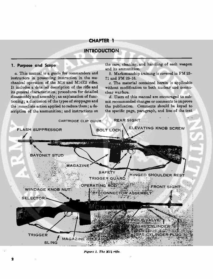
Figure 1. The MI4 rifte.
2
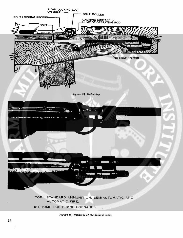
in which the change is recommended. Reasons (4) The lug on the rear of the flash suppres-should be provided for each comment to insure un- sor is used to secure a 'bayonet, a grenadederstanding and complete evaluation. Comments launcher, and a blank firing attachment.should be forwarded direct to the Commandant, (5) The spindle valve is used when launchingUnited States Army Infantry School, Fort Ben- a grenade to prevent gas operation of thening, Ga., 31905. rifle, thus avoiding damage to the weapon.
b. M14EB Rifle.2. Importance of Mechanical Training (1) The U.S. rifle, 7.62mm, M14E2 (fig. 3)
The rifle is the Infantryman's basic weapon. Itis an air-cooled, gas-operated, magaine-gives him an individual and powerful capability fed, shoulder weapon. It is capable offor combat. To benefit the most from this capa-omatic or automatic fire; how-bility, the Infantryman must develop two skills to matic firet i s designed priarilzer autoem-an equal degree: he must be able to fire his weaponwell enough to get hits on battlefield targets, and bly, modified bipod, front and rear hand-he must know enough about its working parts to grip, straight line stock, and a rubberkeep it operating. The Infantryman attains his recoil pad.firing skill in marksmanship training. He learns (2) The M14E2 stock group is the "straighthow to keep his rifle in operable condition through a folding front handgrip which lies flatmechanical training. a folding front handgrip which lies flat
along the bottom of the stock when notin use. The location of the front hand-3. Description of the Rifles grip can be adjusted to one of five posi-
a. M14 Rifle. tions in 1-inch increments to accommo-(1) The U.S. rifle, 7.62mm, M14 (fig. 1) is date all gunners. The rubber recoil pad
a light-weight, air-cooled, gas-operated, reduces the effects of recoil. The hingedmagazine-fed, shoulder weapon. It is de- shoulder rest provides vertical control ofsigned primarily for semiautomatic fire. the butt end of the rifle. The butt swivel
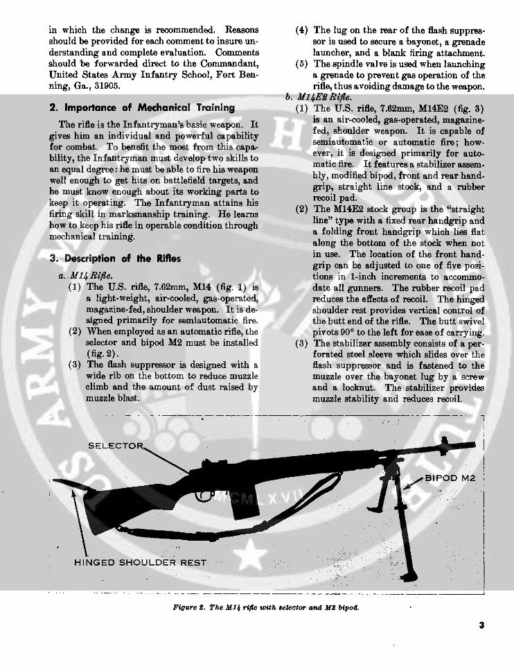
(2) When employed as an automatic rifle, the pivots 90° to the left for ease of carrying.selector and bipod M2 must be installed (3) The stabilizer assembly consists of a per-(fig. 2). forated steel sleeve which slides over the
(3) The flash suppressor is designed with a flash suppressor and is fastened to thewide rib on the bottom to reduce muzzle muzzle over the bayonet lug by a screwclimb and the amount of dust raised by and a locknut. The stabilizer providesmuzzle blast. muzzle stability and reduces recoil.
SELECT OR
; BIPOD M2
HINGED SHOULDER REST
Figure 2. The M14 rife with selector and HM bipod.
3

(4) The M2 bipod is modified by the addition the average firer, by applying rearwardof a sling swivel and a longer pivot pin pressure on the front handgrip, to in-to accommodate the swivel. crease the pressure of the bipod on the
(5) The M14E2 utilizes a sling with an extra ground to approximately 35 pounds, re-hook assembly. The portion of the slingbetween the handgrip and the bipod pro- ducing dispersion considerably. Whenvides additional muzzle control during the weapon is carried at sling arms, thefiring. The portion of the sling between sling must be disconnected from thethe front handgrip and the bipod allows handgrip assembly.
4. General DataWeights in Pounds (approximate): Lengths in Inches (approx.):
M14 rifle with full magazine M14, overall, with flash sup-
and cleaning equipment- 11. Il pressor .------------..- 44yaM14 rifle with full magazine, M14E2, overall, with stabilizer
cleaning equipment, selector, assembly ---------------- 44%and bipod ---------------- 13 Sights:
Empty magazine % Front fixedFull magazine (with ball am- Rear .-..... adjustable (one click
munition) ................- 155 of elevation or
Cleaning equipment .-. . 55 windage moves the
M2 bipod ------------------- 1i strike of the bullet
M14E2 rifle with full maga- .7 centimeter atsine- ------------- 14%4 25 meters).
!iSTABILIZER ASSEMBLY- -E LONG SLINGSHOULDER REST
~~~~~~~~~~' \~~~~~~~~~~
Figure S. The MIIE rifle (to--le st ide view; bottom-right aide vie) ).4
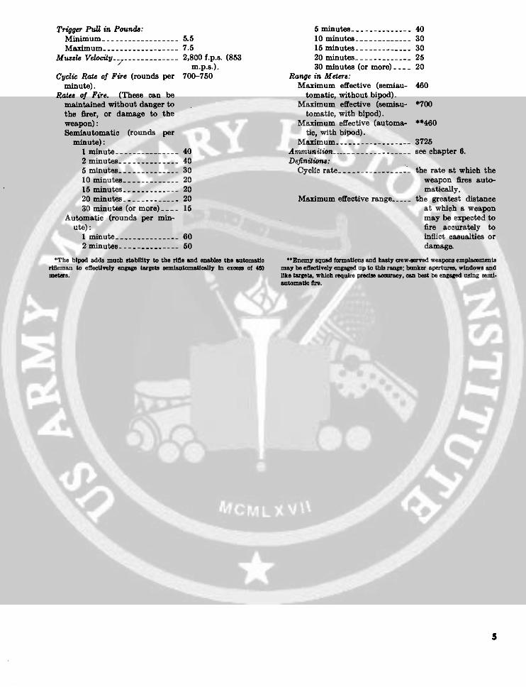
Trigger PuU in Pounds: 5 minutes -.-. . .. 40Minimum ------------------ 5.5 10 minutes ------------ 30Masimum -...... ......- 7.65 15 minutes . 30
Muzzle Vlocity . . ........ 2,800 f.p.s. (853 20 minutes . .......... 25/ m.p.s.). 30 minutes (or more) --- 20
Cyclic Rate of Fire (rounds per 700-750 Range in Meters:minute). Maximum effective (semiau- 460
Rate, of Fire. (These can be tomatic, without bipod).maintained without danger to Maximum effective (semiau- *700the firer, or damage to the tomatic, with bipod).weapon): Maximum effective (automa- **460Semiautomatic (rounds per tic, with bipod).
minute): Maximum .-.. - 37251 minute--------------- 40 Ammunition ....-........ see chapter 6.2 minutes ----.-------- 40 Definitions:5 minutes .- . ......... 30 Cyclic rate -... - -- the rate at which the10 minutes --... . .20 weapon fires auto-15 minutes -. . ..........20 matically.20 minutes -_---------- 20 Maximum effective range .--_ the greatest distance30 minutes (or more) --- 15 at which a weapon
Automatic (rounds per min- may be expected toute): fire accurately to
1 minute -._... . ... 60 inflict casualties or2 minutes .------------ 50 damage.
*The bipod adds much stability to the rifle and enables the satmsto -BEnemy squad formations and hasty crew4erved weapons emplacementarbfl.man to effectively engage tapets secmlutomatlcally In ex of 40 may be effectively engaged up to this range; bunker aperturs, windows andmetls. like taret which requ precise acracy, can best be engaged using smld.
automatic fire.

CHAPTER 2
MECHANICAL TRAINING
5. General curl the remaining fingers around the front of themagazine. Press in on the magazine latch, rotate
a. The individual soldier is authorized to disas- the base of the magazine toward the muzzle endsemble his rifle to the extent called field stripping. of the rifle (fig. 4), and remove it from the maga-Chart I shows the parts he is permitted to dis- zine well. With the knife edge of the right hand,assemble with and without supervision. The pull the operating rod handle all the way to theamount of disassembly he is permitted to perform rear, reach across the receiver with the right thumbwithout supervision is adequate for normal main- and press in on the bolt lock (fig. 5). Verify thetenance.
b. The frequency of disassembly and assembly Chart I. Disassembly Authorizationshould be kept to a minimCum consistent with main-- Main-tenance and instructional requirements. Constant Part ldeu Armorersn.disassembly causes excessive wear of the parts and l pr ,leads to their early unserviceability and to inac-curacy of the weapon. MAIN GROUPS THREE X
c. The rifle has been designed to be taken apart DISASSEMBLY:and put together easily. No force is needed if it BARREL AND RECEIVERis disassembled and assembled correctly. The Gront sight Xparts of one rifle, except the bolt, may be inter- Rear sight Xchanged with those of another when necessary. Flash suppressor .-................. XBolts should never be interchanged for safety Sear release vx- -reasons. Selector and selector
d. As the rifle is disassembled, the parts should shaft lock_ ..-.-.-. ........ XBipod M2 -------------- X
be laid out from left to right, on a clean surface Connector assemblyand in the order of removal. Thismakes assembly (spring and plunger) .- .............. Xeasier because the parts are assembled in the re- Bolt lock- Xverse order of disassembly. The names of the Cartridge clip guide- -... . .... -... I XOperating rod guide-I..C... . .. Xparts (nomenclature) should be taught along with Barrel from receiver .-..-------.------ Xdisassembly and assembly to make further instruc- Stabilizer assemblytion on the rifle easier to understand. M 14E2 Gx
STOCK GROUP:Stock liner -.-.-.- - ------.------ X
6. Clearing the Rifle Upper sling swivelbracket ..-.. X
The first step in handling any weapon is to clear Stock ferrule-------MAGAZINE .-... . ...... X
it. To clear the rifle, first attempt to engage the BOLT - - Xsafety. (If unable to place the safety in the safe Bolt roller from bolt stud ------------- X
position, continue with the second step of remov- FIRING MECHANISM t-.. - . .. .XMagazine latch -------.----..... ..... X
ingthe magazine.) Removethemagazineby plac- Sear from trigger - - Xing the right thumb on the magazine latch and
6

safety, tilt the rifle, and look inside the chamber b. Open the trigger guard and place the firingand receiver to insure that they contain no rounds. mechanism straight down into the receiver, mak-
ing sure that the guide rib on the firing mechanism7. Disassembly Into Three Main Groups enters the recess in the receiver (fig. 9). Place the
butt of the weapon on the left thigh, sights to thea. The three main groups are the filjgwecha- left, insuring the trigger guard has cleared the
nism, e barrel and receiver, and the stock. trigger. With the palm of the right hand, strikeb. After the rifle is cleared, the opeatiniigparts the trigger guard fully engaging it to the receiver.
should be forward for disassembly. To do this,pull back on the operating rod handle and allowthe bolt to go forward.
c. To remove the firing mechanism, grasp therear of the trigger guard with the thumb and fore-finger of your right hand and pull downward andoutward until the mechanism is released (fig. 6).Lift out the firing mechanism. >
d. To separate the barrel and receiver from thestock, lay the weapon on a flat surface with thesights up and muzzle to the left. Grasp the re-ceiver with the left hand over the rear sight and Figure 4. Removing the mnaazine.raise the rifle a few inches. With the right hand,- -strike down on and grasp the small of the stock,separating the barrel and receiver from the stock.The three main groups are shown in figure 7.
e. The components of the M14E2 rifle are shownin figure 8.
8. Assembly of the Three Main Groupsa. Place the barrel and receiver group on a flat
surface, sights down. Pick up the stock group andengage the stock ferrule in the front band, thenlower the stock group onto the barrel and receivergroup. Figure 5. Looking the bolt to the rear.

..
A. RIGHT METHOD a / J _ S -,WR0N04>""
Fgure 6. Removing flring mechanisn.
Figure 7. The three moan groups.
8~ ·,:

BARREL AND RECEIVER GROUP
STABILIZER ASSEMBLY
STOCK GROUP
MODIFIED BIPOD M2FIRING MECHANISM
r
SLING
Figure 8. Components of the M14E2 rifle.
nector assembly (3, fig. 11) clockwise until theelongated hole in the connector assembly is alinedwith the elongated stud on the sear release. Lowerthe front end of the connector assembly and liftthe rear end off the elongated stud of the searrelease.
b. Removing the Operating Rod Spring andOperating Rod Spring Guide. Place the barreland receiver group on a flat surface, sights down,muzzle to the left. With your left hand, pull to-ward the muzzle on the operating rod spring to
Figure 9. Replacing the firing meohanism. relieve pressure on the connector lock (1, fig. 12).
With your right forefinger, pull the connector locktoward you and, allowing the operating rod spring
Group to expand slowly, disconnect and remove the oper-
a. Removing the Connector Assembly. Place ating rod spring and operating rod spring guidethe barrel and receiver group on its left side with (2, fig. 12). Separate these two parts.the operating rod handle up and the muzzle away c. Remnoving the Operating Rod. Turn the bar-from you. On rifles modified for selective firing, rel and receiver group so the sights are up and thepress in and turn the selector until the face marked muzzle is pointing away from you. Pull back the"A" is toward the windage knob (fig. 10). With operating rod handle until the guide lug on its in-the bolt closed, place the right thumb on the rear side surface is ained with the disassembly notchof the connector assembly, the first finger on the on the right side of the receiver. Rotate the oper-sear release bracket and the second finger inside the ating rod downward and outward, then pull it torear of the receiver (fig. 11). Push forward with the rear, disengaging it from the operating rodthe thumb until the forward end of the assembly guide (fig. 13).can be lifted off the connector lock with the thumb d. Removing the Bolt. Grasp the bolt by theand forefinger of the left hand (2, fig. 11). (Note roller and, while sliding it forward, lift it upwardthat the rifle shown in 1, 2, and 3, fig. 11 has not and outward to the right front with a slight rota-been modified for selective firing.) Turn the con- ting motion (fig. 14).
9

e. Rifle Field Stripped. The parts of the bar- away from you. Hold the bolt by the roller andrel and receiver group in their order of disassem- locking lug and place the rear of the bolt on thebly are shown in figure 15. bridge of the receiver, firing pin tang pointed
down. Turn the bolt slightly counterclockwise
10. Assembly of the Barrel and Receiver until the tang of the firing pin clears the bridgeGuide the left locking lug of the bolt into its groove
Group on the left side of the receiver. Lower the righta. Replacing the Bolt. Place the barrel and re- locking lug on its bearing surface and slide the
ceiver on the table, sights up, muzzle pointing bolt halfway to the rear.
A,+~,
Figure 10. Position of the seleotor for removing the con-nector assembly (rifle modified for selective firing).
4d~~~~~~~, /
Figure 11. Removing the connector assembly. Figure 11-Continued.
2 1
Figure 11--COontinued. Figure 12. Removing the operating rod spring and oper-ating rod spring guide.
10

2
Figure 12-COontinued. 7- .
/
/ ~ ' ! Figure 14. Removing the bolt.
Figure 13. Removing operating rod.
b. Replacing the Operating Rod. Holding the hole in the guide can be alined with the connectoroperating rod at the handle, place the front end lock. Lower the guide and push the connectorinto the operating rod guide, and position the rod lock in with the right thumb (fig. 16).
so that the recess in the hump fits over the bolt d. Replacing the Connector Assemrby. Placeroller. Turn the operating rod to the left until the barrel and receiver on its side with the oper-
the guide lug fits into the disassembly notch on the ating rod -handle up, muzzle away from you.receiver, then move the operating rod forward Place the elongated hole in the rear of the con-until the bolt is closed. nector assembly on the elongated stud on the sear
c. Replalcing the, Operating Rod Spring and release (1, fig. 17). Place the thumb of the rightc. Replacing the Operating Rod Spring and hand on the rear of the connector assembly, theOperating Rod Spring Guide. Turn the barrel first finger on the sear release bracket, and theand receiver over so the sights are down and the second finger inside the rear of the receiver.muzzle is to the left. Place the operating rod Pushing toward the muzzle with the right thumbspring guide into the operating rod spring, hump and with the thumb and first finger of the leftup, and feed the loose end of the spring into the hand, turn the front of the connector counterclock-operating rod. Grasp the spring and guide with wise until it can be snapped onto the connectorthe left hand and compress the spring until the lock (2, fig. 17).

IO I- .- 1
Figure 15. Pa,-t of th barel and receiver group i the Order of o:saSembl,.
12

11. Disassembly of the Gas System andHandguard
(fig. 18)Note. Under normal usage the gas cylinder should not
be disassembled as long as the gas piston slides freelywithin the cylinder when the barrel is tilted end-for-endfrom an upright position (bolt should be locked to therear). Disassembly of the gas cylinder is sometimesnecessary after the weapon has been subjected to extremeclimatic conditions.
a. Gas System. Using the wrench of the com-bination tool, loosen and remove the gas cylinderplug. Tilt the muzzle down and remove the gaspiston from the gas cylinder. Unscrew the gas Figue 17. Replaoing the conector assembly.cylinder lock and slide the lock and cylinder for-ward so that the gas port is exposed.
b. Handguard. Slip the front band forward itoward the front sight. Push the handguardtoward the front sight and lift it from the barrel.
12. Assembly of the Gas System and Hand-guard
a. Handguard. Place the rifle on a flat sur-face, sights up and muzzle to the right. Engagethe ends of the band on the handguard with thefront (muzzle) end of the slots that are on therear of the barrel and slide the handguard rear-ward. (Do not snap or force the handguard intoits installed position.) Replace the front band.
.;
2Figure 17ontinued.
Figure 16. Replacing the operating rod spring and oper-ating rod spring guide.
13

FRONT BAND: HAND GUARD
2 Ut I t
GAS CYLINDER GAS PISTON GAS CYLINDER GAS CYLINDERPLUG LOCK
Figure 18. Parts of the gas system; handguard and iront band.
b. GasSystem. Slidethegascylinderrearward tion tool (fig. 21). Slide the combination toolthrough the front band. Tighten the gas cylinder over the head of the screw and place it over thelock by hand to its fully assembled position, then locknut.back it off until the loop is alined with the gas cyl-inder. Replace the gas pisfon with the flat parttoward the barrel and the open end toward themuzzle. When the gas piston is properly seated, a. Use a pointed object to raise the rear of theit will protrude one and one-half inches below the magazine base (fig. 22) until the indentation ongas cylinder (fig. 19). Replace the gas cylinder the base is clear of the magazine. Grasp the maga-plug and tighten it securely with the wrench of zine with either hand, with one finger of the handthe combination tool. covering the base. Remove the base and guide
the spring, one coil at a time, to clear the retain-
13. Removing the Stabilizer Assembly of ing lips of the magazine.the M14E2 Rifle b. Remove and separate the magazine spring
and follower. Figure 23 shows the parts of theTo remove the stabilizer assembly, use the magazine.
wrench end of the combination tool to loosen thelocknut. Then slide the combination tool overthe screw and loosen it. Swing the yoke awayfrom the bayonet lug, and slide the stabilizer as- Reposition the spring inside the follower withsembly off the flash suppressor (fig. 20). the rectangular-shaped end of the spring against
the rear of the follower, and replace the follower14. Replacing the Stabilizer Assembly of and spring inside the magazine. Be sure to fully
the M14E2 Rifle seat the follower. Replace the magazine base (fig.24).
To replace the stabilizer assembly slide it overthe flash suppressor, swing the yoke over the bay- Note. The bolt, rear sight, and the firing mechanism
will not be disassembled by the individual under any cir-onet lug, and tighten the screw with the combina- tumstancs (chart I).
14

Figure 19. Gas piston properly seated.
15

STABILIZER ASSEMBLY
LOCK NUT SCREW
COMBINATION TOOL
V
Figure 20. Removing the stoabilizer asembly.
16

STABILIZER ASSEMBLY
YOKE!LOCK NUT
SCREW
_ i
Figure 21. Replaeing the stabilizer assembly.
17

Figure 24. Replacing the magazine base.
Figure 22. Removing the base of the magazine.
|'< BAS 4MAGAZINE BASE
,< MAGAZINE FOLLOWER
MAGAZINE
MAGAZINE SPRING
Figure 28. Parts of the magazine.
18

CHAPTER 3
OPERATION AND FUNCTIONING
Section I. OPERATION
17. Loading the Magazine (Out of the Rifle) b. A magazine in the weapon can be loadedthrough the top of the receiver with a 5-round
follower (with the bullet end toward the front of clip in the cartridge guide, then exert pressurethe magazine) and apply pressure with the thumb with the thumb or the open end of the combinationto fully seat the round in the magazine (fig. 25). tool on the top round, forcing 5 rounds into the
b. To load the magazine with a 5-round car-. tridge clpoad the magazine with a -round car- magazine (fig. 28). Remove and discard the car-tridge clip, the magazine filler is used (fig. 26). tridge clip. Repeat the process until the maga-Slide the filler over the top rear portion of the zine is loaded pmagazine and insert a 5-round cartridge clip intothe filler. Place either the thumb or the open end 19. Loading and Unloading the Rifleof the combination tool on the top round and pushthe 5 rounds into the magazine. Remove the clip a. Place the safety in the safe position.and repeat the process until 20 rounds have been b. Insert a loaded magazine into the magazineloaded into the magazine, then remove the maga- well, top front first, until the operating rod springzine filler. guide engages the magazine (1, fig. 29), then pull
backward and upward until the magazine snaps18. Loading the Magazine (in the Rifle) into position (2, fig. 29). A click will be heard
which indicates that the magazine is fully seated.a. To load a single round into an empty maga- Pull back and release the operating rod handle,
zine in the weapon, lock the bolt to the rear and allowing the bolt to strip the top round from theengage the safety. Place a round on top of the magazine and load it into the chamber.magazine follower and press down on the round e. Remove the magazine as described in para-and fully seat it in the magazine (fig. 27). graph 6.
Section II. FUNCTIONING
20. Semiautomatic small arms. A knowledge of what happens insidea. Each time a round is fired, the parts inside the rifle during the cycle of operation will help you
the rifle work together in a given order. This is to understand the causes of, and remedies for,the cycle of operation. This cycle is similar in all various stoppages.
19

Figure 217. Loading the magazine with a single round(magazgne in rifle).
Figure 25. Loading the magazine single round (out ofrifle).
Figure 28. Loading the magazine with a 5-rqund cartridgeclip (ma gazine in rifle).
1
Figure 29. Loading the magazine into the rifle.Figure 26. Loading the magazine using the magazine filler
(magazine out of rifle).
20

under pressure of the hammer spring andstrikes the tang of the firing pin, drivingthe firing pin against the primer, and fir-ing the round (fig. 33).
(5) Unlocking. Unlocking (fig. 34) occurs... 34 , - -after the firing of the round. As the
bullet is forced through the barrel by theexpanding gases, a small amount of gasenters the hollow gas piston, the gas cylin-der, and the gas cylinder plug throughthe gas port. The expanding gases force
--.-- the gas cylinder piston to the rear. It in2 turn drives the operating rod and bolt
Figure 29-Continued. rearward. The operating rod cams thebolt roller upward, disengaging the lock-ing lugs on the bolt from the locking re-cesses in the receiver. At this time the
b. The cycle of operation is broken down into bolt is unlocked.eight steps. These steps are listed below, togetherwith a brief description of what occurs inside the Note. The spindle valve must remain in therifle during each step. open position (the slot in the spindle head per-
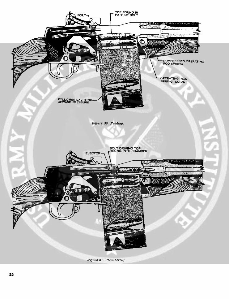
pendicular to the barrel) during all firing, ex-(1) Feeding. Feeding takes place when a cept when launching a grenade (fig. 35).
round is forced into the path of the bolt.round is forced into the path of the bolt. (6) Extracting. Extracting is pulling theThe top round is forced into the path of empty cartridge from the chamber.the bolt by the magazine follower whichthe bolt byf the magazine follower which Slow initial extraction takes place as theis under pressure of the magazine spring bolt unlocks. The bolt in its rearward
(fi2) Charsberg. m30). occurs whenmotion pulls the empty cartridge with it(2) Chamnbering. Chambering occurs when (fig.36).
a round is moved into the chamber. Thistakes place as the bolt goes forward under (7) Ejecting. Ejecting is removing thepressure of the expanding operating rod empty cartridge from the receiver. Asspring, stripping the top round from the soon as the bolt has withdrawn the emptymagazine and driving it forward into the cartridge case clear of the chamber, thechamber (fig. 31). Chambering is com- force of the ejector spring and plungerplete when the extractor snaps into the pushes the bottom edge of the cartridgeextracting groove on the cartridge and base away from the bolt face, throwingthe ejector is forced into the face of the it out and away from the receiver. Whenbolt. the last round has been fired, the bolt is
held in the rearward position by the bolt(3) Locking. Locking begins as the bolt Iroller engages the camming surface in the ock.hump of the operating rod. It is com- (8) Cocking. Cocking is positioning thepleted when the locking lugs of the bolt hammer so that it is ready to fire the nextare fiully seated in the locking recesses of round. The bolt, as it moves to the rear,the receiver (fig. 32). forces the hammer down and rides over
(4) Firing. Firing occurs when the firing it. The hammer is caught by the sear ifpin strikes the primer. As the trigger is the trigger is held to the rear and by thepulled, the trigger lugs are disengaged trigger lugs if the trigger has been re-from the hammer hooks and the hammer leased (fig. 37). In either case, theis released. The hammer moves forward hammer is held in the cocked position.
21
COMPRESSED OPERATINGROD SPRING
OPERATING RODSPRING GUIDE
FOLLOWER EXERTINGUPWARD PRESSURE
Figure 30. Feeding.
BOLT DRIVING TOPEJECTOR NO INTO CHAMBER
Figure 31. Chambering.
22

LOCKING RECESSESIN RECEIVER -- LOCKING LUGS
ER CAMMIN SURFACE INRECESS IN HUMP OF OPERATING ROD
BOLT ROLLER
Figure 82. Locking.
HAMMER HOOK AMMER FIRING PIN
B ROLT7 PRIMER
RIGGER LUGS
TRIGGER
Figure 3S. Firing.
23
RIGHT LOCKING LUGON BOLT
BOLT ROLLERBOLT LOCKING RECESS
CAMMING SURFACE INHUMP OF OPERATING ROD
OPERATING ROD
Figure 54. Unlocking.
TOP: STANDARD AMMUNITION, SEMIAUTOMATIC ANDAUTOMATIC FIRE.
BOTTOM: FOR. FIRING GRENADES
Figure 85. Positiots of the 8pirnde valve.
24
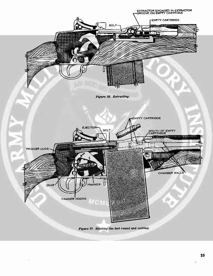
EXTRACTOR ENGAGED IN EXTRACTORROOVE ON EMPTY CARTRIDGE
Figure 36. EBztnating.
EMPTY CARTRIDGE
EJECTOOLTBOLT ~aMOUTH OF EMPTY
ARTRIDGE
TRIGGER LUGS
CHAMBER WALLS
EAR HAMMER
HAMMER HOOKS
Figure 87. Ejecting the last round and cocking.
25

21. Automotic (Rifles Equipped With the sear release allows the sear to move forwardSelector) into a position where it can engage the rear ham-
mer hooks (1, fig. 38). Then, when the bolt drivesa. When the selector is positioned with the face the hammer to the rear, the sear engages the rear
marked "A" to the rear (ear type projection up), hammer hooks and holds the hammer in thethe rifle is set for automatic fire. Turning the se- cocked position.lector to automatic rotates the sear release in posi- c. After the bolt moves forward and locks, thetion to make contact with the sear. shoulder on the operating rod engages the hook
of the connector assembly and forces it forward.b. After the first round has been fired (and with of the connector assembly and forces it forward.This rotates the sear release on the selector shaft,the trigger held to the rear), the operating rod causing the flange on the sear release to push thestarts its rearward movement under pressure of sear to the rear, disengaging it from the rear ham-the expanding gases. As it moves totherear, the mer hooks (2, fig. 38). The hammer will then goconnector assembly moves rearward under pres- forward if the trigger is held to the rear. If thesure of the connector assembly spring. The move- trigger is released at any time prior to the firingment of the connector assembly rotates the sear of the last round, the hammer will be held in therelease on the selector shaft so that the flange on cocked position by the trigger lugs.
SEAR RELEASE @ROTATED FORWARD OPERATING ROD
STARTED REARWARD
CONNECTOR ASSEMBLY MOVEDREARWAAD I l INCH
>- ----- ~" SEAR IN POSITIONTO ENGAGE REARHAMMER HOOKS
1Figure 38. Actions of the connector assembly and its effect on the firing mechanism during automttic flring.
26

SEAR RELEASEROTATED REARWARD
SEAR FORCEDREAR WARD
CONNECTOR ASSEMBLY
FORCED FORWARD
HAMMER RELEASED -
2
Figure J8.-Continued.
27

CHAPTER 4
STOPPAGES AND IMMEDIATE ACTION
22. Stoppages primer. No round should be left in a hotweapon any longer than necessary becausea. A stoppage is any unintentional interruption of the possibility of a cookoffof the possibility of a cookoff.in the cycle of operation. The stoppage may befire. A hangfire is a delay in the
caused by improper functioning of the rifle or functioning of a propelling charge at thefaulty ammunition, time of firing. The amount of delay is
b. Types of Stoppages. unpredictable. A hangfire cannot be dis-(1) Misfire. A misfire is a failure to fire. A tinguished immediately from a misfire
misfire itself is not dangerous, but since (3) Cookoff. A cookoff is the functioning ofit cannot be immediately distinguished a chambered round due to the heat of thefrom a delay in the functioning of the weapon. If the primer or propellingfiring mechanism, or from a hangfire, it charge should cookoff, the projectile willshould be considered as a possible delay be propelled from the weapon with nor-in firing until this possibility has been mal velocity even though no attempt waseliminated. A delay in the functioning made to fire the primer by actuating theof the firing mechanism could result from firing mechanism.the presence of foreign matter such as o. Common Stoppages. The rifle will functionsand, grit, oil and grease. These might efficiently if it is properly cared for. The firercreate a partial mechanical restraint must watch for defects and correct them beforewhich, after some delay, is overcome by they cause a stoppage. Some of the more commoncontinued force applied by the spring, stoppages, their usual causes, and remedies areand the firing pin then striking the shown in chart II.
Chart II. Stoppages: Their Causes and Remedies
stoppo: Cause Remedy
Failure to feed .-.... . Defective or worn part---.... ------------ Replace parts.Dirty or dented magazine ...- . ......... Clean or replace magazsine.Loose gas cylinder plug - -... ---- .-- ..--- Tighten plug.
Failure to chamber ..-..... Lack of lubrication of operating parts -.---- Clean and lubricate parts.Defective ammunition -...--- - Replace ammunition.Dirty chamber .------------------------- Clean chamber.
Failure to lock -.... . .Lack of lubrication of operating parts .----- Clean and lubricate parts.Dirty locking recesses --..... ------------- Clean recesses.Weak operating rod spring .-.... . .... Replace spring.Spindle valve closed -........... ... Open valve.
Failure to fire .-.. - - Defective ammunition --..... . ..... Replace ammunition.Broken firing pin .-...... ------- Replace firing pin.Defective or broken parts in firing mecha- Replace parts or entire firing mechanism.
nism.Failure to unlock -...--- Dirty chamber ----... ------------------- Clean chamber.
Lack of lubrication of operating parts ...-. Clean and lubricate parts.Insufficient gas- -.........- Tighten gas cylinder plug and check spindle
valve.Failure to extract .-..... Dirty chamber ....---------------------- Clean chamber.
Dirty ammunition .--..-- ------.-......-- Replace ammunition.Broken extractor ..-. .................. Replace extractor.
Failure to eject -.... .... Broken ejector or weak ejector spring .-.-- Replace faulty part.Failure to cock .-.... . Defective or broken parts in firing mecha- Replace parts or entire fring mechanism.
nism.
28

23. Immediate Action (1) TAKE the rifle from the shoulder.(2) PULL the operating rod handle slowlyImmediate action is the unhesitating application (2) PULL the operating rod handle slowlyto the rear.
of a probable remedy to reduce a stoppage withoutinvestigating the cause. Immediate action is () LO the r e
taught~in two phas~es. (4) LOCATE the stoppage by observing, asthe operating rod handle is pulled to thea. The first phase is taught as a drill so that the the operating rod handle is pulled to the
rifleman learns to perform it quickly and instinc- rear, what in the chamber, and whattively without thought as to the cause of the stop- has been eected.page. To apply the first phase, with the right fire.hand, palm up, pull the operating rod handle all re.the way to the rear. Release it, aim and attemptto fire. The palm is up to avoid injury to the Normally, the firer will instinctively apply im-hand in event of a cookoff or hangfire (fig. 39). mediate action which in most instances reduces
b. If the first phase of immediate action fails to the stoppage even when caused by a hangfire orreduce a stoppage, the second phase of immediate misfire.action is applied. The five key words used to help d. The normal cause of a misfire is faulty am-remember the steps in the second phase are: munition. Therefore, further use of ammunitionTAKE, PULL, LOOK, LOCATE, and RE- from that lot should be suspended and reported toDUCE. maintenance for disposition.
Figure 39. Applying immediate action.
29

CHAPTER 5
MAINTENANCE
24. Genereal LOCKING RECESSESMaintenance includes all measures taken to keep
the rifle in operating condition. This includesnormal cleaning, inspection for defective parts,repair, and lubrication.
25. Cleaning Materials, Lubricants, andEquipment
a. Cleaning Materials.(1) Bore cleaner (cleaning compound sol-
vent (CR)) is used primarily for clean-ing the bdre; however, it can be used onall metal parts for a temporary (1 day)protection from rust.
CAMMING SURFACES INHUMP OF OPERATING ROD
; zEC E I VRECEIVER
L' K
1 2
Figure 40. Points to apply rifle grease. Figure 40-Continued.
30

(2) Hot, soapy water or plain hot water is (3) OE 10 engine oil may be used as a fieldno substitute for bore cleaner and wril expedient under combat conditions whenonly be used when bore cleaner is not the oils prescribed in (1) and (2) aboveavailable. cannot be obtained. However, as soon as
(3) Drycleaning solvent is used for cleaning possible the weapon should be cleaned andrifles which are coated with grease, oil, lubricated with the proper, authorizedor corrosion-preventive compounds. lubricants.
(4) Carbon-removing compound (PC111-A) (4) Rifle grease should be applied to thoseis used on stubborn carbon deposits by working surfaces shown i figure 40.soaking and brushing. This process c. Epipet.
(1) A complete set of maintenance equip-must be followed by the use of dryclean- ment (fig. 41) is stored in the stock of theing solvent. M14 rifle and consists of a-
b. lubricants. (a) Combination tool.(1) Lubricating oil, general purpose, is used (b) Chamber cleaning brush.t
for lubricating the rifle at normal tem- (c) Plastic case lubricant.peratures (PL special). (d) Small arms cleaning rod case.
(2) Lubricating oil, weapons (LAW) is used (e) Small arms cleaning rod section (4for low temperatures (below 00). each).
-Ns".;1 _ \ R- M
1Figue 41. Maintenance equipment.Figure 41l. Maintennce equipment.
DRIVER RATCHET (f) Cleaning patch holder.(g) Small arms bore cleaning brush.
(2) The combination tool can be used as eithera 20° offset screwdriver or as a gas plugwrench (figs. 42 and 43).
(a) The handle of the combination tool isalso used as the cleaning rod handle.To do this, allow the cleaning rod ex-
~x/ _ tension of the tool to fall from the toolD7790463 handle so that it hangs perpendicular.
BRUSH
2Insure the M14 chamber brush is used to prevent barrel dam-age. The M14 brush is one-balf inch shorter than the M1 chainm-
Figure 41Continued. her brush.
31

Assemble the four sections of the clean- b. Gas Cylinder Plug. Pour a small quantitying rod and screw into the threaded of bore cleaner in the plug, insert and rotate thehole in the cleaning rod extension. bore cleaning brush. Remove the brush, cleanEither the bore brush or the cleaning and dry the plug with patches.patch holder may be attached to the end c. Gas Cylinder. Install the patch holder on aof the cleaning rod. section of the cleaning rod. Put two patches in
(b) The plastic lubricant case (fig. 44) is the holder, moisten them with bore cleaner andclosed with a screw cap which has a swab the cylinder bore. Dry the cylinder borestem (applicator) attached that is used with clean patches. Use no abrasives in cleaningto apply oil drop by drop on one end. the cylinder and do not oil the interior surfaces.The cap is fitted with a gasket to pre- d. Gas Piston. Saturate patches with borevent oil leakage. The other end has cleaner and wipe the exterior surface of the pistonanother screw cap and contains rifle COMBINATION TOOL
grease.BRUSH
26. Cleaning the Rifle LUBRICANT CASEa. Procedures for Cleaning Chamber and Bore.
The rifle must be cleaned after it has been firedbecause firing deposits primer fouling, powderashes, carbon and metal fouling. The ammuni-tion has a noncorrosive primer which makes clean-ing easier, but not less important. The primerstill leaves a deposit that may collect moisture andpromote rust if it is not removed. The proceduresfor cleaning the chamber and bore are described infigures 45 and 46. These procedures will insurethat the bore is cleaned evenly and will prevent CASE, CLEANING RODforeign matter from being pushed into the receiver CONTAINING: 4 SECTIONS
1 BRUSHfrom the bore. Upon completion of firing, bore 1 HOLDERcleaner should be applied for ease of further acleaning. Figure 41--Continued.
Figure 42. Combination tool used as a screwtdriver.
32

Figure 45. Oombination tool used as a wrench.
Otherwise, merely wipe the magazine assemblyclean and dry, then oil it.
h. Stabilizer Assembly. The stabilizer assem-bly should be removed and cleaned with a stiffbrush to remove all carbon or other particles whichmay block the gas ports.
i. All Other Parts. Use a dry cloth to removeall dirt or sand from other parts and exterior sur-faces. Apply a light coat of oil to the metal parts
Figure 44. Plastic lubricant ease. and rub raw linseed oil into the wooden parts.as clean as possible. Install the bore cleaning Care must be taken to prevent linseed oil from get-brush on a section of the cleaning rod. Moisten ting on metal parts.the brush with bore cleaner and clean the interior j. After Firing. The rifle must be thoroughlyof the piston. Wipe the piston dry, but do not oil. cleaned no later than the evening of the day it isThe gas system incorporates a self-cleaning sec- fired. For three consecutive days thereafter, checktion and functions within very close tolerances. for evidence of fouling by running a clean patchA piston does not have to be shiny to function through the bore and inspecting it. The boreproperly. Do not use abrasives to clean the piston. should be lightly oiled after each inspection.
e. Face of the Bolt. Clean the face of the boltwith a patch and bore cleaner, paying particular 27. Normal Maintenanceattention to its inside edges. Remove the bore a. The rifle should be inspected daily, when incleaner with dry patches and oil the part lightly. use, for evidence of rust and general appearance.
f. Spindle Valve. Depress the valve and rotate A light coat of oil should be maintained on allit several times after each day's firing. Do not dis- metal parts, except the gas piston, interior of theassemble it. gas cylinder, and the gas plug.
g. Magazine. Inspect the interior of the maga- b. The daily inspection should also reveal anyzine by depressing the follower with the thumb. defects such as burred, worn or cracked parts.If the interior is dirty, disassemble the magazine Defects should be reported to the armorer for cor-and clean it, then lightly oil the component parts. rection.
33

BRUSH )
SECTION
LOCK HY | ., )BRUSH
/ RVA LOF SECTION AND BRUSH
34.
A.ISTAIND. REMOVAL OF SECTION AND BRUSH
34

TWO PATCHES IN THE PATCH HOLDER
SCREW THE JOINTED CLEANING ROD TOGETHER
FIRMLY (LESS THE PATCH HOLDERI GENTLY INSERT
IT INTO THE BORE ALL THE WAY. (AN AUTHORIZED
SOLID NONJOINTED ROD MAY BE USED). FLARE THE
PATCHES OUT THEN INSERT THE PATCH HOLDER WITH
WET PATCHES INTO THE CHAMBER. PUSH THE
THREADED END INTO THE CHAMBER UNTIL IT
TOUCHES THE CLEANING ROD. HOLD IT THERE
WITH ONE HAND.
2
Figure 45-Continued.
35

SCREW THE ROD AS SHOWN BY ARROW I ON TOTHE PATCH HOLDER. WITH THE OTHER HAND, UNTILTHE PATCHES TURN WITH THE ROD. PULL THE PATCHESINTO THE CHAMBER FIRMLY: AT SAME TIME TURNINGTHE ROD CLOCKWISE, BY GRASPING IT BETWEEN THEHANDLE AND THE MUZZLE OF THE WEAPON, ASSHOWN BY ARROW I & 2 TURN THE ROD SEVERALTIMES CLOCKWISE, PULLING THE PATCHES INTO THECHAMBER FIRMLY, WIPING OUT THE CHAMBERTHOROUGHLY.
3Figure 45--Contnued.
SCREW THE PATCH HOLDER OFF THE ROD.INSERT THE ROD. LESS THE PATCH HOLDER.GENTLY INTO THE BORE, ALL THE WAY.
PULL SINGLE PATCH THROUGH BORESTRAIGHT AND PARALLEL TO BORE.
Figure 46. Cleaning the bore.
36

INSERT THE HOLDER WITH ONE PATCH INTO THECHAMBER UNTIL THE tHREAbS OF it TOUCHES THE ROD:SCREW THE ROD CLOCKWISE INTO THE ,PATCH HOLDER
2
ipure 46--Continued.
PULL PATCH THROUGH BOREIN STRAIGHT LINE WITH AXISOF BORE.AND OUT THE MUZZLE
Figure 46-Continued.
37

c. A muzzle plug should never be used on the knob can be turned without extremerifle. It causes moisture to collect in the bore form- difficulty (1, fig. 47).ing rust and creating a safety hazard. (b) If the elevation knob is extremely loose
d. Obtaining the proper rear sight tension is and the rear sight aperture will notextremely important; without it, the sight will not raise, the windage knob nut must behold its adjustment in elevation. During normal turned in a clockwise direction, onemaintenance, and prior to firing, the rear sight click at a time, until the aperture canmust be checked for correct sight tension. The be raisedindications of improper sight tension are: (a) To check for proper tension, the pro-
(1) Elevation knobextremelydifficulttoturn. cedures listed below should be fol-(2) Elevation knob turns freely without an led
audible click.(a) If the elevation knob is extremely diffi- . Raise the aperture to its full height.
cult to turn, rotate the windage knob Lower the aperture two clicks.nut counterclockwise one click at a tine 3. Grasp the rifle with the fingers aroundwith the screwdriver portion of the the small of the stock and exertcombination tool. After each click at- downward pressure on the aperturetempt to turn the elevation knob. Re- with the thumb of the same handpeat this process until the elevation (2, fig. 47).
Pigure 47. Adjustttg sight tension.
38

(d) If the aperture drops, sight tension be used if necessary to remove oil or grease. Partsmust be adjusted. To do this, the that show signs of wear may be wiped with a patchowindage knob nut must be turned in lightly dampened with lubricating oil (LAW).a clockwise direction, one click' at a It is best to keep the rifle as close as possible totime, until the aperture can no longer outside temperatures at all times to prevent thebe pushed down as indicated in (c)S collection of moisture which occurs when coldabove. If theproper tension cannot be metal comes in contact with warm air. Whenobtained, the rifle must be turned in to the rifle is brought into a warm room, it shouldthe unit armorer. not be cleaned until it has reached room tempera-
ture.28. Special Maintenance d. In hot, humid climates or if exposed to salt
a. Before firing the rifle, the bore and the cham- water or salt water atmosphere, the rifle must bebher should be cleaned and dried. A light coat of inspected thoroughly each day for moisture andoil should be placed on all other metal parts, rust. It should be kept lightly oiled with specialexcept those which come in contact with ammuni- preservative lubricating oil. Raw linseed oiltion, the gas piston, interior of the gas cylinder, should be frequently applied to the wooden partsand the gas plug. to prevent swelling.
b. Before firing, rifle grease should be applied e. In hot, dry climates, the rifle must be cleanedto the parts indicated in figure 40. A small daily or more often to remove sand and/or dustamount of grease is taken up on the stem of the from the bore and working parts. In sandy areas,grease container cap and is applied at each place. the rifle should be kept dry. The muzzle and re-Rifle grease is not used in extremely cold tempera- ceiver should be kept covered during sand andtures or when the rifle is exposed to extremes of dust storms. Wooden parts must be kept oiledsand and dust. with raw linseed oil to prevent drying. The rifle
o. In cold climates (temperatures below freez- should be lightly oiled when sand or dust condi-ing) the rifle must be kept free of moisture and tions decrease.excess oil. Moisture and excess oil on the working /. Special instructions on' caring for the rifleparts cause them to operate sluggishly or fail com- when it is subject to nuclear, biological or chemi-pletely. The rifle must be disassembled and wiped cal contamination can be found in TM 3-220 andwith a clean dry cloth. Drycleaning solvent may FM 21-40.
_--
Figure 47--Contnued.
39

CHAPTER 6
AMMUNITION
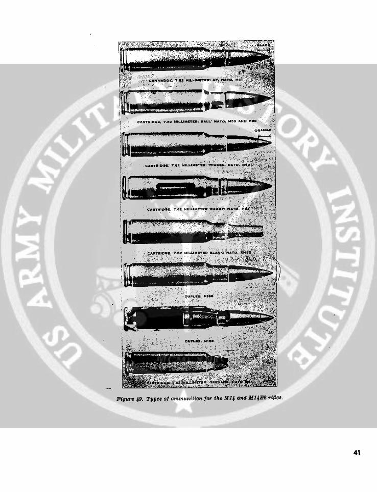
29. General d. Grenade Cartridge. The M64 rifle grenadeThe M14 rifle fires several types of ammunition, cartridge is used for launching grenades and pyro-
The rifleman should be able to recognize them and technics. The cartridge can be identified by itsknow which type is best for certain targets. He five-pointed, star-crimped end.should also know how to care for the ammunition. e. Blank. The M82 blank cartridge is used to
a. Figure 48 shows the parts of a typical car- aid realism in training. It can be identified by itstridge. long narrow neck.
b. The term "bullet" refers only to a small arms f. Dummny. The M63 dummy cartridge has sixprojectile; the term "ball" was originally used to longitudinal corrugations approximately one-describe the ball-shaped bullet of very early small third the length of the case. There are no mark-arms ammunition. The term "ball ammnunition" ings on the bullet and there is no primer in thenow refers to a cartridge with a general purpose base of the cartridge. It is used in training forsolid core bullet intended for use against person- dry firing exercises.nel and material targets.
31. Packaging30. Description a. 5-Round Cartridge Clip. Ammunition is
The types of ammunition can be identified by prepacked in 5-round cartridge clips. Twelvetheir individual markings (fig. 49). clips are packed in a cloth bandoleer. Seven ban-
a. Armor Piercing. The M61 armor piercing doleers are packed in a can and two cans arecartridge is used against lightly armored targets. packed in a case.The cartridge can be identified by its black tip. b. £O-Round Carton. Ammunition is also
b. Ball. The three types of ball ammunition, packed in 20-round cartons. Twenty-three car-(M59, M80 and M198 duplex) are used against tons are packed in a can and two cans are packedpersonnel and unarmored targets. The M59 and in a case.M80 cartridges can be identified by their unpainted c. Magazine Filler. The magazine filler is antips. The M198 duplex round can be identified adapter which fits over the top of an empty maga-by its green tip. zine (when the magazine is not in the weapon) and
c. Tracer. The M62 tracer cartridge is used forc. Trer. TheM62tracercartridgeisusedfor makes it easier to load. One magazine filler isindicating target areas and adjusting fire. Thecartridge can be identified by its orange tip. packed in each case of ammunition.
32. Care, Handling, and PreservationB ff.-.--SULLtET a. Care should be taken to prevent ammunition
boxes fromn becoming broken or damaged.b. Ammunition should not be exposed to the
direct rays of the sun. If the powder is heated,excessive pressure may develop. This conditionwill affect ammunition performance and creates asafety hazard.
NPgure 48. Parts of a oartridge. C. Ammunition should be kept clean and dry.
40
NA TO1 Me\. BAND4
OUPLt. ,,
Figure 49. Type of ammunition for the Mfl and MJ4B2 rife.
41

CHAPTER 7
ACCESSORIES
33. M2 Bipod positions on the launcher. On the bottom portionThe M2 bipod (fig. 50) is a light, folding mount of the muzzle end of the launcher, there is a clip-
which clamps onto the gas cylinder and gas cylin- type retainer spring used to hold the grenade onder lock of the rifle, the launcher at the desired position prior to firing.
a. Installation (fig. 51). Placethejaws of the The unmarked groove located above the retaineryoke assembly so that they encircle the gas cylinder spring is a safety groove that prevents the grenadeat the gas cylinder lock. Tighten the self-locking from slipping off the launcher if the retainer clipbolt with the combination tool, securing the jaws reaks.
to the gas cylinder, a. Installation. To install the grenadeb. Removal. Using the combination tool, loosen launcher, slide the launcher over the flash suppres-
the bolt located beneath the yoke assembly and sor. Push the clip latch rearward securing it tothe bolt located beneath the yoke assembly andremove the bipod from the rifle. the bayonet lug of the flash suppressor (fig. 55).
Caution: Do not remove the cap screw from b. Removal. To remove the grenade launcher,the jaw assembly. pull downward on the handle of the clip latch,
releasing it from the bayonet lug on the flash sup-34. M6 Bayonet Knife and M8A1 Bayonet pressor, and slide the launcher from the flash sup-
Knife Scabbard pressor.The M6 bayonet knife (fig. 52) is utilized for 36. Mi5 Grenade Launcher Sight
close combat, guarding prisoners and riot control. The grenade launcher sight provides an angular
The b 18A1 bayonet scabbard is used to carry the measurement of elevation for firing grenades andbayonet knife. can be used for both low angle (direct firing) and
a. Instcal ationz. Install the bayonet knife to the high angle firing.rifle by aliining the groove of the bayonet handle a. Installation. Install the sight to the mount-with the bayonet lug on the flash suppressor and ing plate, alining notches of the plate with thethe loop of the top portion of the handle on the click springtipsof thesight (fig. 56). Turn sightflash suppressor. Slide the knife rearward until clockwise until the index line is alined with the 0 °
the lugs of the latching lever snap over the bayonet index on the mounting plate. At this position,lug (fig. 53). the leveling bubble should be level. If the bubble
b. Redeoreal. Grasp the handle of the bayonet cannot be leveled, the rifle should be turned in toand depress the latching lever on the handle, re- the unit armorer.
leasing the bayonet lug from the groove in the Note. The mounting plate for the &M-15 sight is in-handle. Slide the bayonet from the rifle. stalled by support maintenance ONLY.
b. Removal. Turn sight counterclockwise un-til the tips of the clip springs are alined with the
The M76 grenade launcher (fig. 54) is attached notches in the mounting plate; remove the sightto the barrel of the rifle for launching grenades. from the mounting plate (fig. 56). When not inThe barrel of the launcher contains nine annular use retain the sight in its carrying case.grooves, numbered 6 to 1, 2A, 3A and 4A. Whengrooves, numbered to 1, 2A, 3A and 4A. When Note. Removal and mounting of the mounting platefiring grenades, these are utilized to obtain dif- from the stock is accomplished by support maintenanceferent ranges by placing the grenade at different personnel ONLY.
42

/ / YOKE ASSEMBLY
ASSEMBLY /.,,OKBOLT
PIVOT PLUNGERBUTTON
PIVOT PLUNGERBUTTON
RIGHT LEG ASSEMBLY
Figure 50. M2 bipod.
Figure 51. Intallation of Mt bipod.43

BAYONET-KNIFE SCABBARD M8A1
BAYONET-KNIFE M6
Figure 52. M6 bayonet knife and M8A1 bayonet scabbard.
BAYONET LUG
BAYONET KNIFE - M6
Figure 53. M14 r nfle with bayonet knife.
44

Figure 54. M76 grenade launcher.
Ai .i r '-
Figure 55. M14 rifle with M76 grenade launcher.
37. M12 Blank Firing Attachment and M3 deflector shield and a guide lug with spring
Breech Shield plunger.The blank firing attachment and breech shield a. Installation (fig. 58).
(fig. 57) are designed for use when firing blank (1) Blank in the muzzle opening of the o-shcartridges. The blank firing attachment, which suppressor. Pull out on the clip latchsecures the attachment to the bayonet lug of the and push down on the top of the orificeflash suppressor, consists of an orifice tube and a tube of the blank firing attachment. Re-spring clip latch. The breech shield, which se- lease the clip spring latch securing thecures the shield to the cartridge clip guide, is used cut away portion of the latch to the bayo-with the blank firing attachment and consists of a net lug.
43

Lb. PO STONING S IE I I.
Figure 56. Installation of M15 grenade launcher sight.
(2) Breech shield. Insert the guide lug of ASPRING CLIP LATCHthe breech shield into the slot of the car-tridge clip guide. Using an empty blankcartridge, press in. on the spring plungerand push down on the breech shield, lock-ing it to the cartridge clip guide.
b. Removal. pJ:ORIFICE TUBE
(1) Blank firing attachment. In removing N FIRIG ATTACHMENTthe blank firing attachment from the rifle,pull outward on the spring clip latchreleasing it from the bayonet lug. Turnthe attachment either to the left or theright of the bayonet lug and slide the at-tachment from the flash suppressor. \i'3-
(2) Breech shield. Using an empty blank SPRINGcartridge, or any suitable object, press in PLUNGERon the spring plunger located on the HIELDguide lug of the breech shield. Lift the BREE Sbreech shield from the cartridge clipguide. Figure 57. M12 blank ftring attachment and MS breeol~~~~~~~guide. ~~~~~~~~shield
46

EMPTY RLANK ICARTRIDGE I
SRING PLUNGER
,-/GUIDE LUG
BREECH SHIELD
FLASH SUPPRESSOR
SPIN CUPP
ORITUBE
Pigures 58. Imtaallatlon of blankL fltnp attachmm and breechiek
47

38. Winier Trigger Kit /The winter trigger kit (figs. 59 and 60) is util-
ized during cold weather and arctic operations byspecial authorization of the theater commander.It consists of two woodscrews, a winter triggerassembly and a winter safety. The safety can beeasily operated by the firer while wearing heavygloves or mittens because of its long protrudingtang which extends approximately one and one-half inches below the firing mechanism. Figure 59. Winter trigger t.
Figure 60. M14 rifle wich winter trigger kit.
48

APPENDIX
REFERENCES
FM 21-5 Military Training Management.FM 21-6 Techniques of Military Instruction.FM 21-40 Small Unit Procedures in Chemical, Biological, and Radiological (CBR)
Operations.FM 22-5 Drill and Ceremonies.FM 23-71 Rifle Marksmanship.TM 3-220 Chemical, Biological, and Radiological (CBR) Decontamination.TM 9-1005-223-12 Operator and Organizational Maintenance Manual 7.62-mm Rifle M14 and
Rifle Bipod M2.TM 9-1005-223-20P Organizational Maintenance Repair Parts and Special Tool Lists.TM 9-1305--200 Small-Arms Ammunition.TM 9-2205 Fundamentals of Small Arms.TM 38-230 Preservation, Packaging, and Packing of Military Supplies and Equipment.AR 385-40 Accident Reporting and Records.AR 38543 Regulations for Firing Ammunition for Training, Target Practice, and
Combat.
49

By Order of the Secretary of the Army:
HAROLD K. JOHNSON,General, United States Army,
Official: Chief of Staff.J. C. LAMBERT,Major General, United States Army,The Adjutant General.
Distribution:Active Army:
DCSPER (2) LOGCOMD (1) MFSS (1)DCSPR (2) USACDC (2) USAOC&S (1)ACSI (2) Armies (25) USAQMS (1)DSCLOG (2) Corps (3) USASCS (1)DCSOPS (2) Div (10 USACHS (1)CORC (2) Div Arty (5) USAES (1)CRD (1) Bde (5) USATSCH (1)COA (1) Regt (5) USACMLCS (1)CINFO (1) Gp (1) USASESCS (1)TIG (1) BG (5) USMA (2)TJAGSA (1) CC (5) Svc Colleges (5)CNGB (2) Bn (5) Mil Msn (1)ACSFOR (2) Co/Btry (5) USATC (10) exceptUSCONARC (5) Br Sve Sch (5) except USATC Inf (25)ARADCOM (2) USAMPS (1)ARADCOM Rgn (1)
NG: State AG (3); units-same as Active Army except allowance is four copies to each unit.USAR: Units-same as Active Army except allowance is two copies to each unit.For explanation of abbreviations used, see AR 320-50.
50* U.S. GOVERNMENT PRINTINGG FFI: 195 O-7770


![Army fm 5-472 c2 [materials testing]](https://img.pdfslide.net/doc/110x75/58a392f21a28abb1348b4833/army-fm-5-472-c2-materials-testing.jpg)