Embed Size (px)
Citation preview
Publ. MHV...K-E-06/07
MHV PROPORTIONAL DIRECTIONAL CONTROL VALVEManual operationSizes 12, 16, 20, 25, 32 Series MHV...K
FEATURES
* The load independent output flow is proportionalto the input signal (lever position).
* The pump pressure always corresponds to theuser pressure, +3,6,8 or 12 bar (43, 86, 114 or172 psi) Dp compensator.
* The built-in pump-unloading valve results in:- very low power turned into heat;- minimum loading of the prime mover.
* User speed is precisely controlled under all loadconditions.
* Progressive regulating curve; no pressure peakswhen switching; sensitive control even foralternating pressures.
* Constant working speed of differential cylindersat the different regulating flow to the valve bygrinding angle.
* Constant recirculation pressure independent of thenumber of units.
* Any limiting of flow for every user port.
* Proportional directional control valves alsoavailable as:
· Hydraulic proportional series MOV and· Electrical proportional series MEV.
Any combination of these control options ispossible.
* The sandwich system allows a construction upto 8 control valves.
* Electrical pressure cut off at port A, B or A andB, available on request.
2
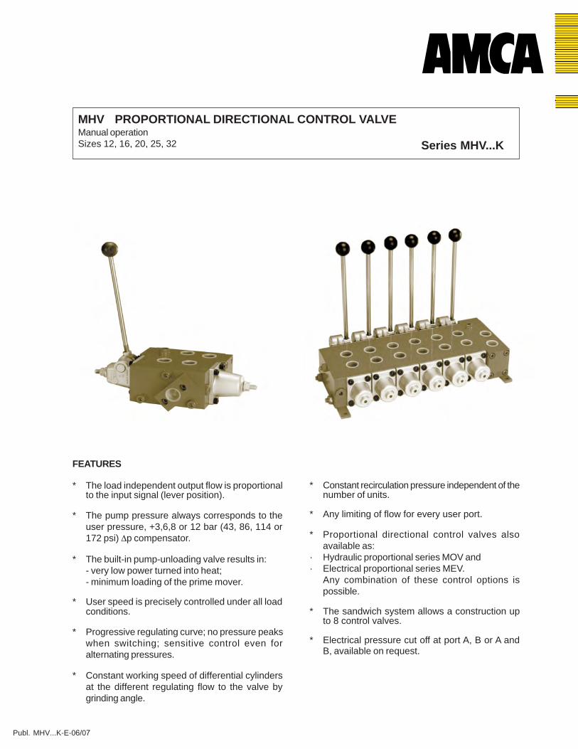
Operating pressure (P,A,B) ...350 bar (5000 psi)Maximum return pressure (T): - aluminium endcaps 15 bar (214 psi) - cast iron endcaps 30 bar (428 psi)Dp compensator 3; 6; 8 or 12 bar (43; 86; 114 or 172 psi)Pressure setting range 5...350 bar (72...5000 psi)Flow range ...800 l/min (...211 USgpm)- with 32 cSt at 40°CFluid Mineral oil according to DIN 51524/51525Fluid temperature range -35...+80°C (-31°...+176°F)Viscosity range 2,8...380 cSt, optimal 30 cSt
Contamination level max. according to NAS 1638 Class 9 or ISO 18/15Mounting position optionalLever, std. Stainless steel
Size working ports: MHV12 : 1/2" BSP (SAE optional)MHV16 : 3/4" BSP (SAE optional)MHV20 : 1" BSP (SAE optional)MHV25 : 1 1/4" BSP (SAE optional)MHV32 : 1 1/2" BSP (SAE optional)
Max. flow in l/min. (USgpm) related to the Dp in bar (psi) over the compensator, per nominal bore:
TECHNICAL DATA
3 (43) 1) 6 (86) 8 (114) 12 (172) 2) MHV12 50 (13) 80 (21) 90 (24) 100 (26) MHV16 100 (26) 140 (37) 155 (41) 180 (47) MHV20 160 (42) 225 (59) 250 (66) 300 (79) MHV25 250 (66) 350 (92) 390 (103) 500 (132) MHV32 400 (106) 500 (132) 550 (145) 800 (211)
Size
∆p compensator lever force[N] lbs
2.2 - 4.940 - 8.933 - 7.456 - 12.680 - 18.0
P
A
P
P
AP
A
A
P
aA
T
B
T
T
BT
B
B
T
b0B
Spool Symbols Operation Characteristic
A In neutral position all4/3 way ports blocked 3)
4/3 wayB In neutral position,
A - T,20% of nominal
4/3 wayC
A+B - T,In neutral position,
20% of nominal
4/3 wayD
B - T,In neutral position,
20% of nominal
4/2 wayE
70% of nominal boreP - B and A - T,
3/2 wayO
3/2 way
4/3 way
M
(3/3)
K
4/2 way
4/2 way
G
F
B
T
T
P
AP
B
B
B
B
T
T
T
P
AP
A
P
A
A
port T leakage flow 3)Port B out of function
P-B,Port A out of function
position a additional 3)Port A out of function
In neutral position,A+B - T,
In neutral position allports blocked 3)
20% of nominal
types
bore 3)
bore 3)
bore 3)
bore 3)
70% of nominal bore
Operation CharacteristicSymbolstypesSpool
a 0 b
XX
X
1) Standard2) Due to loss of pressure c.q. energy conversion into
heat, we recommend the next largest series.
3) Recirculation at low pressure only with MUV
3
DESCRIPTION
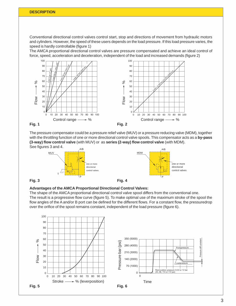
Conventional directional control valves control start, stop and directions of movement from hydraulic motorsand cylinders. However, the speed of these users depends on the load pressure. If this load pressure varies, thespeed is hardly controllable (figure 1)The AMCA proportional directional control valves are pressure compensated and achieve an ideal control offorce, speed, acceleration and deceleration, independent of the load and increased demands (figure 2)
The pressure compensator could be a pressure relief valve (MUV) or a pressure reducing valve (MDM), togetherwith the throttling function of one or more directional control valve spools. This compensator acts as a by-pass(3-way) flow control valve (with MUV) or as series (2-way) flow control valve (with MDM).See figures 3 and 4.
100
90
80
70
60
50
40
30
20
10
1000
20 4030 50 7060 80 10090
Load
235
bar
(335
7 ps
i)
Load
185
bar
(264
3 ps
i)
Load
5 b
ar (7
1 ps
i)
Load
245 b
ar (35
00 ps
i)
Load
1 to
350 b
ar (14
,29 to
5000
psi)
0
20
10
40
30
50
60
70
80
90
100
0 10 3020 40 8050 60 70 90 100
Advantages of the AMCA Proportional Directional Control Valves:The shape of the AMCA proportional directional control valve spool differs from the conventional one.The result is a progressive flow curve (figure 5). To make optimal use of the maximum stroke of the spool theflow angles of the A and/or B port can be defined for the different flows. For a constant flow, the pressuredropover the orifice of the spool remains constant, independent of the load pressure (figure 6).
MUV
Tcontrol valvesdirectionalone or more
A/B
P
one or moredirectionalcontrol valves
P
A/BMDM
Pre
ssur
e di
ff.co
nsta
nt350 (5000)
280 (4000)
210 (3000)
140 (2000)
(43, 86, 114 or 172 psi)Recirculation pressure 3,6,8 or 12 bar
70 (1000)
00
Loadpressure
Pumppressure
100 20 4030 50 7060 80 90 1000
10
20
30
40
50
60
70
80
100
90
Stroke % (leverposition)
Flow
%
Time
Pres
sure
bar
(psi
)Fig. 1
Control range %
Flow
%
Control range %Fl
ow
%Fig. 2
Fig. 3 Fig. 4
Fig. 5 Fig. 6
4
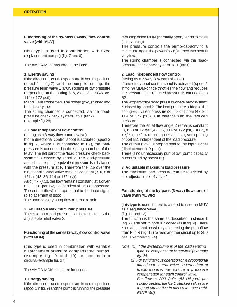
Functioning of the by-pass (3-way) flow controlvalve (with MUV)
(this type is used in combination with fixeddisplacement pumps) (fig. 7 and 8)
The AMCA-MUV has three functions:
1. Energy savingIf the directional control spools are in neutral position(spool 1 in fig.7), and the pump is running, thepressure relief valve 1 (MUV) opens at low pressure(depending on the spring 3, 6, 8 or 12 bar (43, 86,114 or 172 psi)).P and T are connected. The power (pxqv) turned intoheat is very low.The spring chamber is connected, via the “load-pressure check back system”, to T (tank).(example fig.26)
2. Load independent flow control(acting as a 3-way flow control valve)If one directional control spool is actuated (spool 2in fig. 7, where P is connected to B2), the load-pressure is connected to the spring chamber of theMUV. The left part of the “load pressure check backsystem” is closed by spool 2. The load-pressureadded to the spring-equivalent pressure is in balancewith the pressure at P. Therefore the Dp over thedirectional control valve remains constant (3, 6, 8 or12 bar (43, 86, 114 or 172 psi)).As qv = k. Dp, the flow remains constant, at a givenopening of port B2, independent of the load-pressure.The output (flow) is proportional to the input signal(displacement of spool).The unnecessary pumpflow returns to tank.
3. Adjustable maximum load pressureThe maximum load-pressure can be restricted by theadjustable relief valve 2.
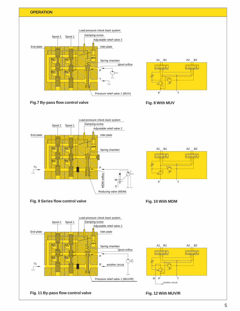
Functioning of the series (2-way) flow control valve(with MDM)
(this type is used in combination with variabledisplacement/pressure compensated pumps,(example fig. 9 and 10) or accumulatorcircuits.(example fig. 27)
The AMCA-MDM has three functions:
1. Energy savingIf the directional control spools are in neutral position(spool 1 in fig. 9) and the pump is running, the pressure
OPERATION
reducing valve MDM (normally open) tends to close(is balancing).The pressure controls the pump-capacity to aminimum. Again the power (p x qv) turned into heat isvery low.The spring chamber is connected, via the “load-pressure check back system” to T (tank).
2. Load independent flow control(acting as a 2-way flow control valve)If one directional control spool is actuated (spool 2in fig. 9) MDM-orifice throttles the flow and reducesthe pressure. This reduced pressure is connected toB2.The left part of the “load pressure check back system”is closed by spool 2. The load pressure added to thespring-equivalent pressure (3, 6, 8 or 12 bar (43, 86,114 or 172 psi)) is in balance with the reducedpressure.Therefore the Dp at flow angle 2 remains constant(3, 6, 8 or 12 bar (42, 86, 114 or 172 psi)). As qv =k. Dp, the flow remains constant at a given openingof port B2, independent of the load pressure.The output (flow) is proportional to the input signal(displacement of spool).There is no unnecessary pumpflow (pump capacityis controlled by pressure).
3. Adjustable maximum load pressureThe maximum load pressure can be restricted bythe adjustable relief valve 2.
Functioning of the by-pass (3-way) flow controlvalve (with MUV/R)
(this type is used if there is a need to use the MUVas a sequence valve)(fig. 11 and 12)The function is the same as described in clause 1(fig. 7). The return bore is blocked (as in fig. 9). Thereis an additional possibility of directing the pumpflowfrom P to R (fig. 12) to feed another circuit up to 350bar. (Example fig. 24)
Note: (1) If the systempump is of the load sensingtype. no compensator is required (examplefig. 28).
(2) For simultanious operation of te proportionaldirectional control valve, independent ofloadpressure, we advice a pressurecompensator for each control valve.For flows < 200 l/min. (53 USgpm) percontrol secton, the MFC stacked valves area good alternative in this case. (see Publ.F12/F18K)
5
OPERATION
another circuit
Spool 2
B2
End plate
A2
MD
M o
rific
e
Pressure relief valve 1 (MUV)
Pressure relief valve 1 (MUV/R)
Reducing valve (MDM)
0
M
Inlet plate
Spring chamber
B1
T
P
A1
spool orifice
T1
End plate
Load-pressure check back system
Adjustable relief valve 2Spool 1 Damping-screw
B1B2
A1A2
spool orifice
another circuitR
P
Spring chamber
Inlet plate
Damping-screwLoad-pressure check back system
Spool 1Spool 2Adjustable relief valve 2
Adjustable relief valve 2
Load-pressure check back system
T1
B2 B1
End plate
A2 A1
P
Spring chamber
Inlet plate
Spool 1Spool 2 Damping-screw
P
A1 B1
P
T
T
A1 B1
A2 B2
A2 B2
A1
R TP
B1 A2 B2
Fig. 9 Series flow control valve Fig. 10 With MDM
Fig.7 By-pass flow control valve Fig. 8 With MUV
Fig. 11 By-pass flow control valve Fig. 12 With MUV/R
6
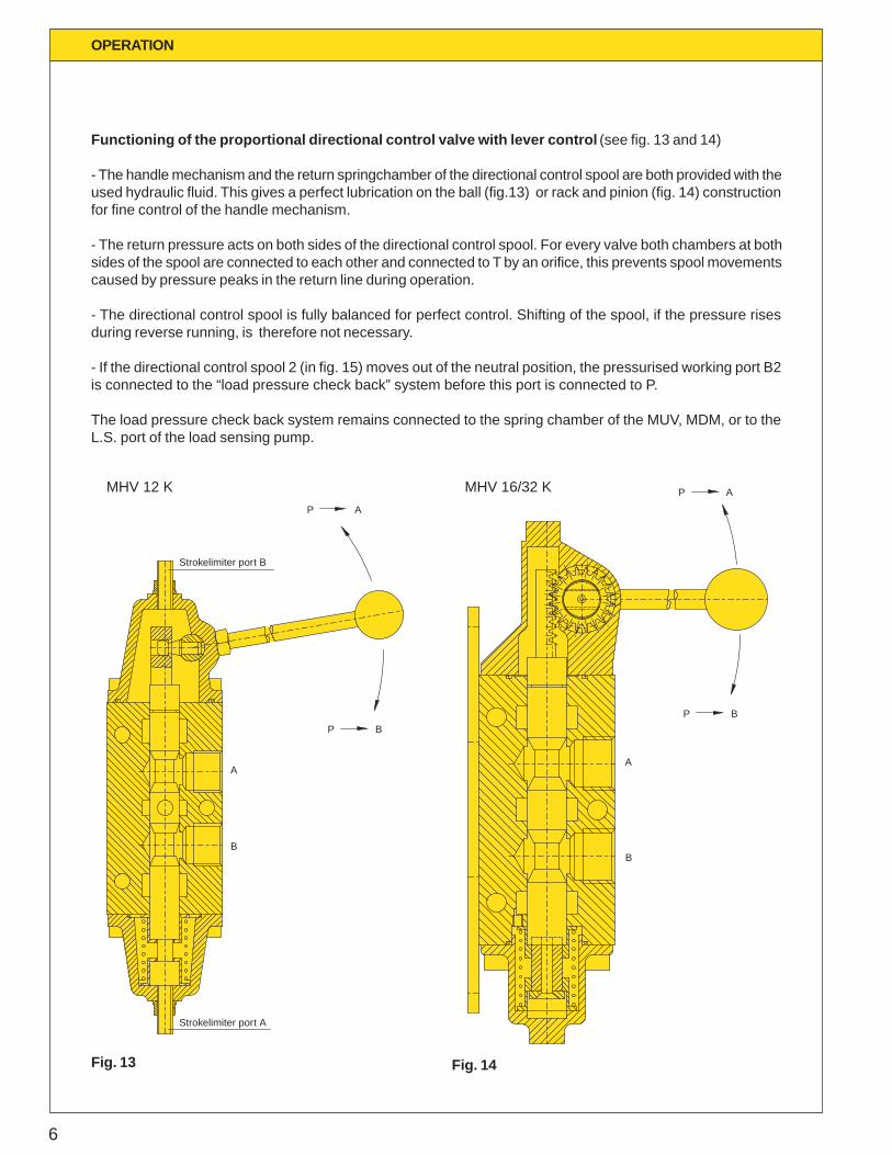
Functioning of the proportional directional control valve with lever control (see fig. 13 and 14)
- The handle mechanism and the return springchamber of the directional control spool are both provided with theused hydraulic fluid. This gives a perfect lubrication on the ball (fig.13) or rack and pinion (fig. 14) constructionfor fine control of the handle mechanism.
- The return pressure acts on both sides of the directional control spool. For every valve both chambers at bothsides of the spool are connected to each other and connected to T by an orifice, this prevents spool movementscaused by pressure peaks in the return line during operation.
- The directional control spool is fully balanced for perfect control. Shifting of the spool, if the pressure risesduring reverse running, is therefore not necessary.
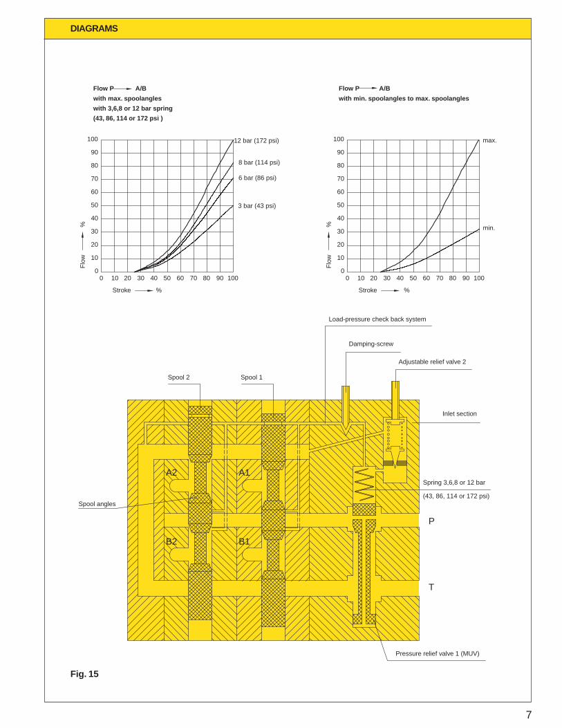
- If the directional control spool 2 (in fig. 15) moves out of the neutral position, the pressurised working port B2is connected to the “load pressure check back” system before this port is connected to P.
The load pressure check back system remains connected to the spring chamber of the MUV, MDM, or to theL.S. port of the load sensing pump.
OPERATION
Strokelimiter port A
B
A
B
A
Strokelimiter port B
P B
P A
P B
P AMHV 12 K MHV 16/32 K
Fig. 13 Fig. 14
7
DIAGRAMS
Flow P A/B
with min. spoolangles to max. spoolangles
with 3,6,8 or 12 bar spring
with max. spoolangles
Flow P A/B
8 bar (114 psi)
3 bar (43 psi)
6 bar (86 psi)
12 bar (172 psi)
min.
max.
(43, 86, 114 or 172 psi )
100
90
80
70
60
50
40
30
20
10
Flow
%
0
Stroke %
100
90
80
70
60
50
40
30
20
10
Flow
%
050200 10 30 40 8060 70 90 100 50200 10 30 40 8060 70 90 100
Stroke %
Spool angles
Spring 3,6,8 or 12 bar
B2 B1
T
P
A2 A1
Spool 2 Spool 1
(43, 86, 114 or 172 psi)
Load-pressure check back system
Damping-screw
Adjustable relief valve 2
Inlet section
Pressure relief valve 1 (MUV)
Fig. 15
8
DIAGRAMS
0
0
50 100 150 200
3 (43)
6 (86)
9 (129)
12 (172)
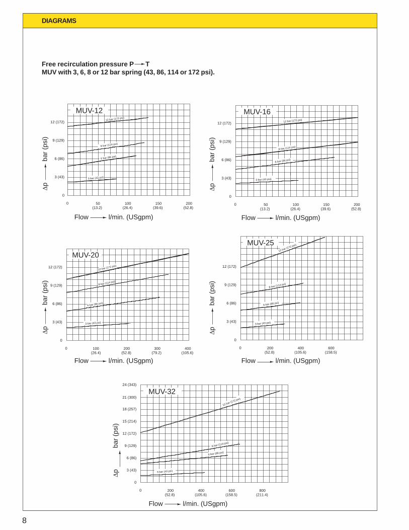
3 bar (43 psi)
6 bar (86 psi)
8 bar (114 psi)
12 bar (172 psi)
MUV-12
(13.2) (26.4) (39.6) (52.8)
MUV-1612 bar (172 psi)
8 bar (114 psi)
6 bar (86 psi)
3 bar (43 psi)
9 (129)
3 (43)
0
6 (86)
12 (172)
(26.4)0
(13.2)50 100
(39.6)150
(52.8)200
400300
MUV-20
(79.2) (105.6)
12 bar (172 psi)
8 bar (114 psi)
6 bar (86 psi)
3 bar (43 psi)
9 (129)
3 (43)
0
6 (86)
12 (172)
0(26.4)100
(52.8)200 400 600
MUV-25
(52.8)200
(105.6) (158.5)
12 bar (172 psi)
8 bar (114 psi)
6 bar (86 psi)
3 bar (43 psi)
9 (129)
6 (86)
3 (43)
0
12 (172)
0
3 bar (43 psi)
6 bar (86 psi)
12 bar (172 psi)
8 bar (114 psi)
800
15 (214)
18 (257)
21 (300)
24 (343)
MUV-32
(211.4)
3 (43)
6 (86)
9 (129)
12 (172)
0
0(52.8)
200(105.6)
400(158.5)
600
Flow l/min. (USgpm)
Dp
b
ar (p
si)
Flow l/min. (USgpm)D
p
bar
(psi
)
Flow l/min. (USgpm)
Dp
b
ar (p
si)
Flow l/min. (USgpm)
Dp
b
ar (p
si)
Flow l/min. (USgpm)
Dp
b
ar (p
si)
Free recirculation pressure P TMUV with 3, 6, 8 or 12 bar spring (43, 86, 114 or 172 psi).
9
DIAGRAMS
A1-TMHV-25
25 (357)
MHV-12A1-T
20 (286)
15 (214)
10 (143)
∆p
bar (
psi)
5 (72)
00
A6-T
B6-T
50Flow l/min. (USgpm)
B1-T
80
A1-T
MHV-16
00 100 140
A6-T
B6-T
B1-T
00
MHV-20
A6-T
A1-T
B6-T
B1-T
225160
A1-T
00
MHV-32
A6-T
B6-T
400
B1-T
560
00
250
A6-T
B6-T
B1-T
350
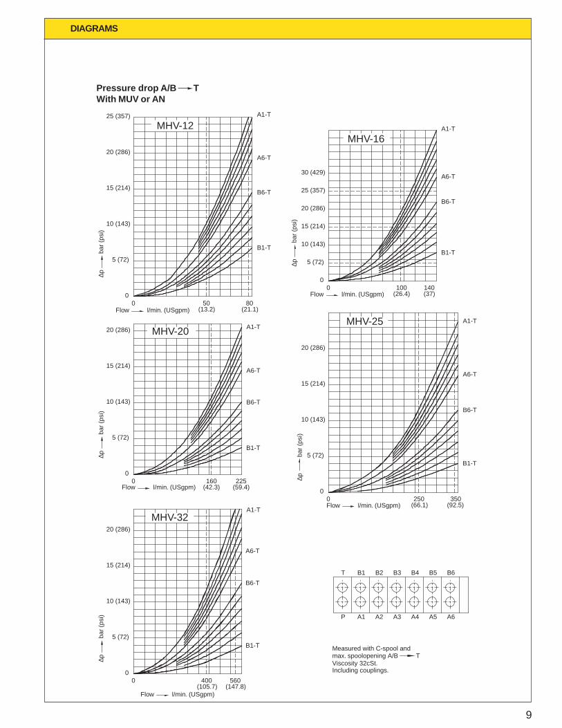
max. spoolopening A/B TMeasured with C-spool and
T B1 B2 B3 B4 B5
Including couplings.Viscosity 32cSt.
P A1 A2 A3 A4 A5
B6
A6
(13.2) (21.1)
5 (72)
10 (143)
15 (214)
20 (286)
25 (357)
30 (429)
(26.4) (37)Flow l/min. (USgpm)
5 (72)
10 (143)
15 (214)
20 (286)
Flow l/min. (USgpm) (42.3) (59.4)
5 (72)
10 (143)
15 (214)
20 (286)
Flow l/min. (USgpm) (66.1) (92.5)
5 (72)
10 (143)
15 (214)
20 (286)
Flow l/min. (USgpm)(105.7) (147.8)
∆p
bar (
psi)
∆p
bar (
psi)
∆p
bar (
psi)
∆p
bar (
psi)
Pressure drop A/B TWith MUV or AN
10
DIAGRAMS
MHV-16
MHV-25
MHV-12A1,B1-T1
A2,B2-T1
MHV-20
00 50
A3,B3-T1
A4,B4-T1
A5,B5-T1
A6,B6-T1
80 900
0
A1,B1-T1
A2,B2-T1
A3,B3-T1A4,B4-T1
A5,B5-T1
A6,B6-T1
100 140
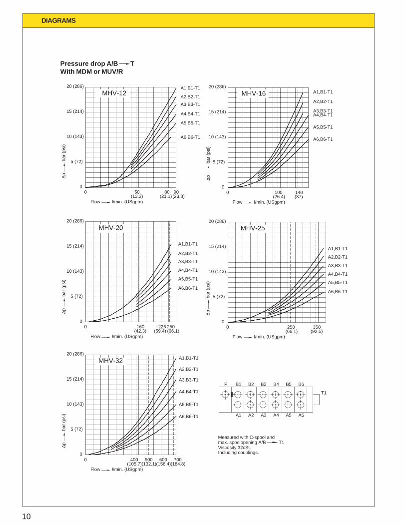
Measured with C-spool and
Including couplings.
225
MHV-32
00 160
A1,B1-T1
A2,B2-T1
A3,B3-T1
A4,B4-T1
A5,B5-T1
A6,B6-T1
250
A1,B1-T1
00
6000
0 400 500
A2,B2-T1
A3,B3-T1
A4,B4-T1
A5,B5-T1
A6,B6-T1
P B1 B2 B3
A1 A3A2
Viscosity 32cSt.
700
A3,B3-T1
A1,B1-T1
A2,B2-T1
A4,B4-T1
A5,B5-T1
A6,B6-T1
250 350
B4 B5 B6
A5A4 A6
T1
5 (72)
10 (143)
15 (214)
20 (286)
(13.2) (21.1) (23.8)Flow l/min. (USgpm)
5 (72)
10 (143)
15 (214)
20 (286)
(26.4) (37)Flow l/min. (USgpm)
5 (72)
10 (143)
15 (214)
20 (286)
(42.3) (59.4) (66.1)Flow l/min. (USgpm)
5 (72)
10 (143)
15 (214)
20 (286)
(66.1) (92.5)Flow l/min. (USgpm)
5 (72)
10 (143)
15 (214)
20 (286)
(105.7)(132.1)(158.4)(184.8)Flow l/min. (USgpm)
∆p
bar (
psi)
∆p
bar (
psi)
∆p
bar (
psi)
∆p
bar (
psi)
∆p
bar (
psi)
max. spoolopening A/B T1
Pressure drop A/B TWith MDM or MUV/R
11
DIAGRAMS
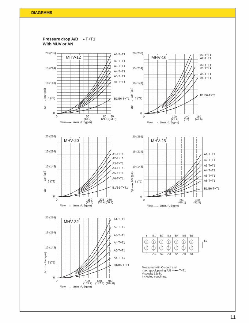
3502500225 2501600
A1-T+T1A2-T+T1
A3-T+T1A4-T+T1
A5-T+T1
A6-T+T1
A1-T+T1
A2-T+T1
A3-T+T1
A4-T+T1
A5-T+T1
B1/B6-T+T1
B1/B6-T+T1
A6-T+T1
00
MHV-12
50 80 90
0
MHV-20
MHV-16
00
A1-T+T1A2-T+T1
A3-T+T1A4-T+T1
A5-T+T1A6-T+T1
180140100
B1/B6-T+T1
MHV-25
0
A2-T+T1
A1-T+T1
A3-T+T1
A4-T+T1
A5-T+T1
A6-T+T1
B1/B6-T+T1
A1-T+T1
A2-T+T1
A3-T+T1
A4-T+T1
A5-T+T1
A6-T+T1
B1/B6-T+T1
MHV-32
00 400 560 700
Viscosity 32cSt.
Measured with C-spool and
A1
B1
P
T
A4A3A2
B2 B3 B4
A6A5
B5 B6
T1
Including couplings.
5 (72)
10 (143)
15 (214)
20 (286)
(13.2) (21.1)(23.8)Flow l/min. (USgpm)
5 (72)
10 (143)
15 (214)
20 (286)
Flow l/min. (USgpm)(26.4) (37) (47.6)
5 (72)
10 (143)
15 (214)
20 (286)
(42.3) (59.4)(66.1)Flow l/min. (USgpm)
5 (72)
10 (143)
15 (214)
20 (286)
(66.1) (92.5)Flow l/min. (USgpm)
5 (72)
10 (143)
15 (214)
20 (286)
(105.7) (147.8) (184.8)Flow l/min. (USgpm)
∆p
bar (
psi)
∆p
bar (
psi)
∆p
bar (
psi)
∆p
bar (
psi)
∆p
bar (
psi)
max. spoolopening A/B T+T1
Pressure drop A/B T+T1With MUV or AN
12
T
P
MUV MHV A B AP
AP/TBAMHVMDM
P T1
3: AP-12-K
1: MUV-12-K2: MHV-12-KSFWA-30/30
B
A
P
T
2
BA
P T
A
P T
B
3
1
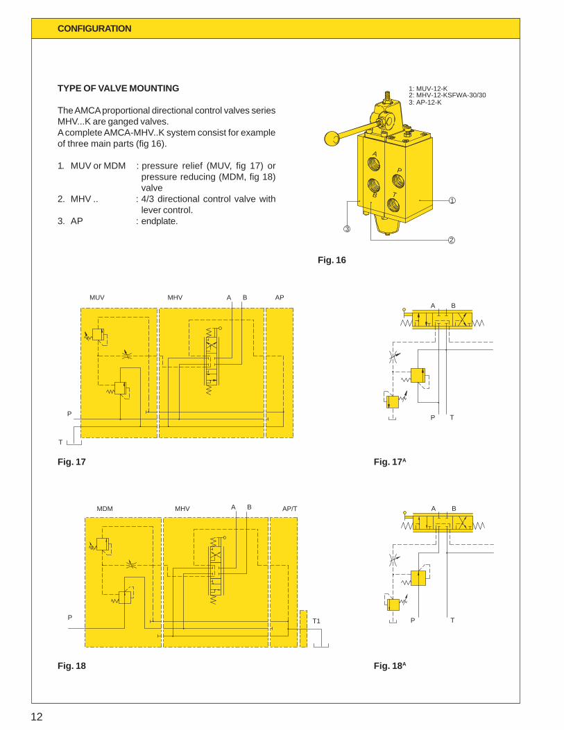
TYPE OF VALVE MOUNTING
The AMCA proportional directional control valves seriesMHV...K are ganged valves.A complete AMCA-MHV..K system consist for exampleof three main parts (fig 16).
1. MUV or MDM : pressure relief (MUV, fig 17) orpressure reducing (MDM, fig 18)valve
2. MHV .. : 4/3 directional control valve withlever control.
3. AP : endplate.
CONFIGURATION
Fig. 16
Fig. 17 AFig. 17
Fig. 18 AFig. 18
13
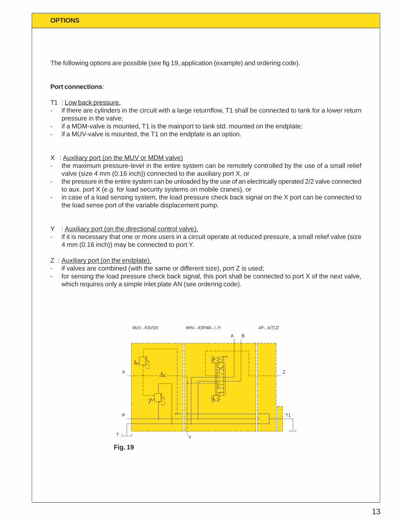
The following options are possible (see fig 19, application (example) and ordering code).
Port connections :
T1 : Low back pressure.- if there are cylinders in the circuit with a large returnflow, T1 shall be connected to tank for a lower return
pressure in the valve;- if a MDM-valve is mounted, T1 is the mainport to tank std. mounted on the endplate;- if a MUV-valve is mounted, the T1 on the endplate is an option.
X : Auxiliary port (on the MUV or MDM valve)- the maximum pressure-level in the entire system can be remotely controlled by the use of a small relief
valve (size 4 mm (0.16 inch)) connected to the auxiliary port X, or- the pressure in the entire system can be unloaded by the use of an electrically operated 2/2 valve connected
to aux. port X (e.g. for load security systems on mobile cranes), or- in case of a load sensing system, the load pressure check back signal on the X port can be connected to
the load sense port of the variable displacement pump.
Y : Auxiliary port (on the directional control valve).- if it is necessary that one or more users in a circuit operate at reduced pressure, a small relief valve (size
4 mm (0.16 inch)) may be connected to port Y.
Z : Auxiliary port (on the endplate).- if valves are combined (with the same or different size), port Z is used;- for sensing the load pressure check back signal, this port shall be connected to port X of the next valve,
which requires only a simple inlet plate AN (see ordering code).
OPTIONS
MHV-..-KSFWA-../../Y
T
P
X
Y
MUV-..-KSVS/X
T1
Z
AP-..-K/T1/Z
A B
Fig. 19
14
VARIANTS / OPTIONS
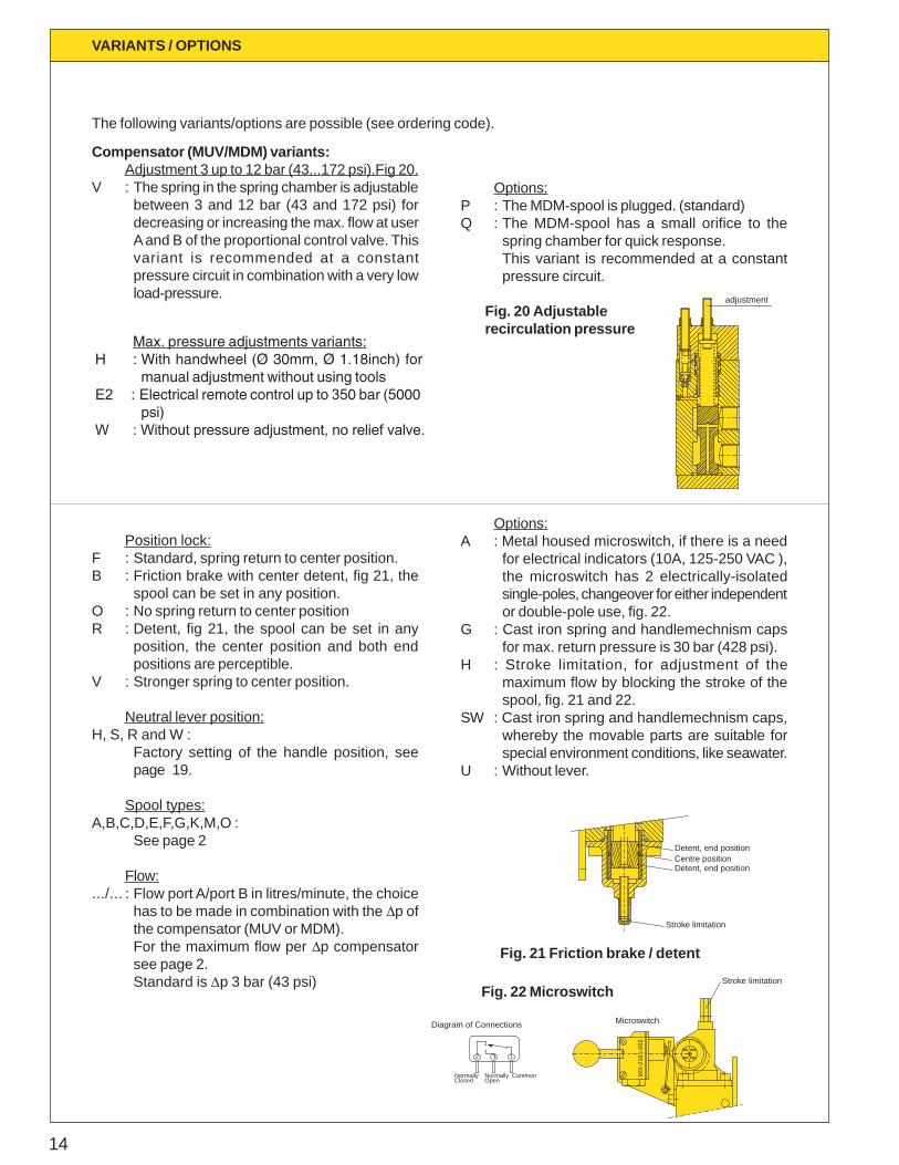
Compensator (MUV/MDM) variants:Adjustment 3 up to 12 bar (43...172 psi).Fig 20.
V : The spring in the spring chamber is adjustablebetween 3 and 12 bar (43 and 172 psi) fordecreasing or increasing the max. flow at userA and B of the proportional control valve. Thisvariant is recommended at a constantpressure circuit in combination with a very lowload-pressure.
Position lock:F : Standard, spring return to center position.B : Friction brake with center detent, fig 21, the
spool can be set in any position.O : No spring return to center positionR : Detent, fig 21, the spool can be set in any
position, the center position and both endpositions are perceptible.
V : Stronger spring to center position.
Neutral lever position:H, S, R and W :
Factory setting of the handle position, seepage 19.
Spool types:A,B,C,D,E,F,G,K,M,O :
See page 2
Flow:.../... : Flow port A/port B in litres/minute, the choice
has to be made in combination with the Dp ofthe compensator (MUV or MDM).For the maximum flow per Dp compensatorsee page 2.Standard is Dp 3 bar (43 psi)
Options:P : The MDM-spool is plugged. (standard)Q : The MDM-spool has a small orifice to the
spring chamber for quick response.This variant is recommended at a constantpressure circuit.
Options:A : Metal housed microswitch, if there is a need
for electrical indicators (10A, 125-250 VAC ),the microswitch has 2 electrically-isolatedsingle-poles, changeover for either independentor double-pole use, fig. 22.
G : Cast iron spring and handlemechnism capsfor max. return pressure is 30 bar (428 psi).
H : Stroke limitation, for adjustment of themaximum flow by blocking the stroke of thespool, fig. 21 and 22.
SW : Cast iron spring and handlemechnism caps,whereby the movable parts are suitable forspecial environment conditions, like seawater.
U : Without lever.
The following variants/options are possible (see ordering code).
Fig. 20 Adjustablerecirculation pressure
Fig. 21 Friction brake / detent
Detent, end positionCentre positionDetent, end position
Stroke limitation
Stroke limitation
WX
-216
1-00
2
Microswitch
Normally NormallyClosed Open
32 1
Common
Diagram of Connections
adjustment
Fig. 22 Microswitch
Max. pressure adjustments variants:H : With handwheel (Ø 30mm, Ø 1.18inch) for
manual adjustment without using toolsE2 : Electrical remote control up to 350 bar (5000
psi)W : Without pressure adjustment, no relief valve.
15
APPLICATIONS
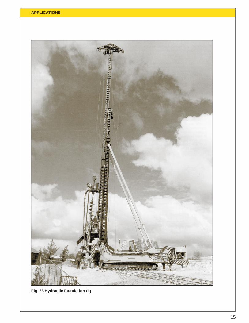
Fig. 23 Hydraulic foundation rig
16
ACFFAMCAConstantFlowFilter
MUV
MU
V
MHV AP
T1
MH
VM
HV
MH
V
MUV/R MHV MHV
MUV MHV MHV
AP/T
MHV MHV
MH
VA
P
MHV AP
APPLICATIONS
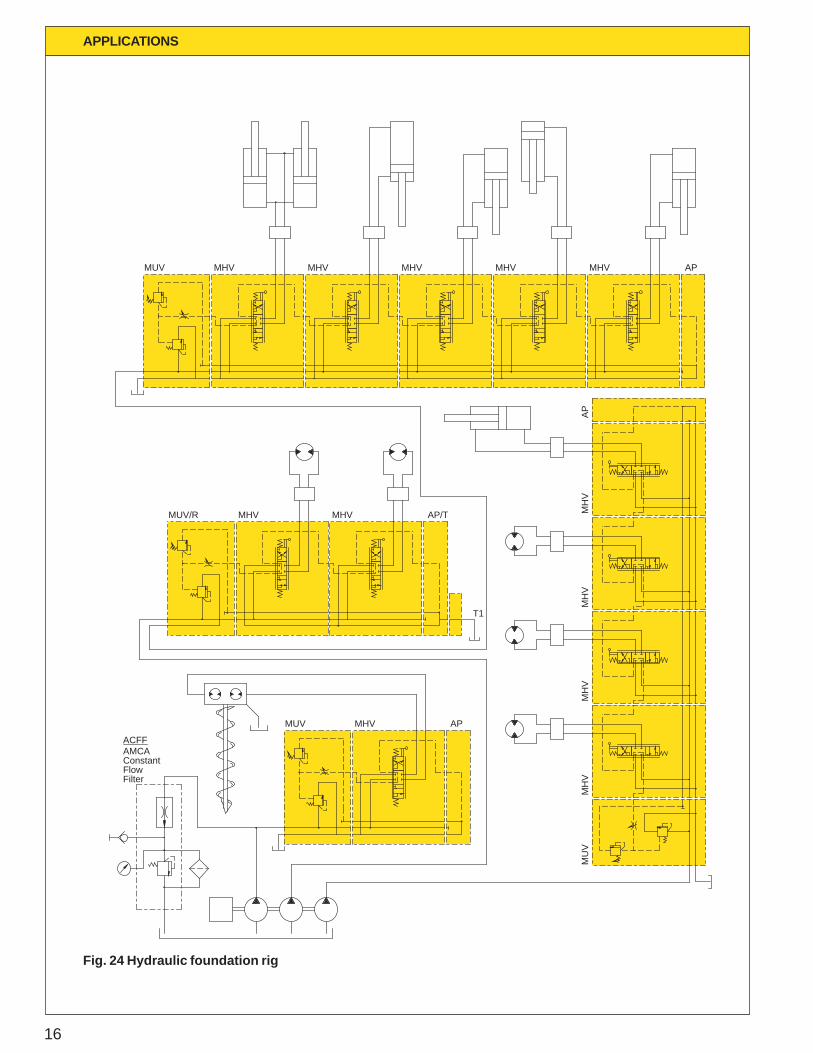
Fig. 24 Hydraulic foundation rig
17
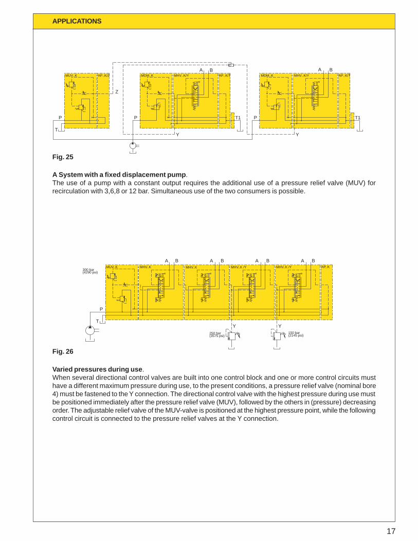
A System with a fixed displacement pump .The use of a pump with a constant output requires the additional use of a pressure relief valve (MUV) forrecirculation with 3,6,8 or 12 bar. Simultaneous use of the two consumers is possible.
TY
MUV..K
P
Z
AP..K/Z MHV..K/Y
P
MDM..K
T1
A BAP..K/T
Y
AP..K/T
P
MDM..K MHV..K/YA B
T1
MHV..K /Y
YT
P
Y
MUV..K MHV..K
BBA AMHV..K
A BMHV..K /Y
A BAP..K
300 bar(4290 psi)
250 bar(3575 psi)
150 bar(2145 psi)
APPLICATIONS
Fig. 25
Varied pressures during use .When several directional control valves are built into one control block and one or more control circuits musthave a different maximum pressure during use, to the present conditions, a pressure relief valve (nominal bore4) must be fastened to the Y connection. The directional control valve with the highest pressure during use mustbe positioned immediately after the pressure relief valve (MUV), followed by the others in (pressure) decreasingorder. The adjustable relief valve of the MUV-valve is positioned at the highest pressure point, while the followingcontrol circuit is connected to the pressure relief valves at the Y connection.
Fig. 26
18
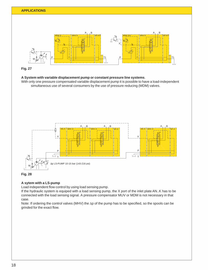
A System with variable displacement pump or constant pressure line systems .With only one pressure compensated variable displacement pump it is possible to have a load-independent
simultaneous use of several consumers by the use of pressure reducing (MDM) valves.
M
MHV..K
P
MDM..K MHV..K
T1
BAAP..K/T
P
X
MDM..K/XA B
AP..K/T
T1
Fig. 27
M
P
AN..K MHV..K MHV..KA B A
AP..K
T
P
MHV..K
X
AN..K AP..KBB A
T
X
∆p LS-PUMP 10-15 bar (143-216 psi)
A sytem with a LS-pumpLoad independent flow control by using load sensing pump.If the hydraulic system is equiped with a load sensing pump, the X port of the inlet plate AN..K has to beconnected with the load sensing signal. A pressure compensator MUV or MDM is not necessary in thatcase.Note: If ordering the control valves (MHV) the Dp of the pump has to be specified, so the spools can begrinded for the exact flow.
Fig. 28
APPLICATIONS
19
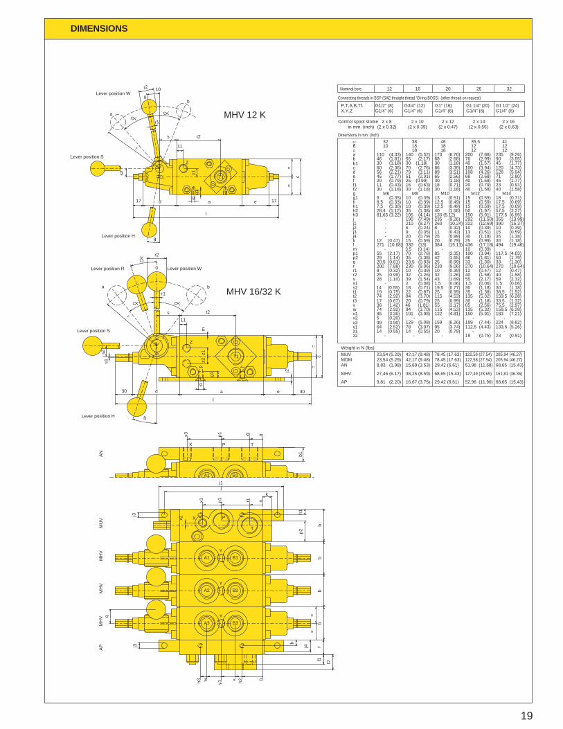
DIMENSIONS
j3
q
j3
j1j
x1 p1 t1
k
x2
h3 w y1
v h2 0
f2f1fj4
h
==
bb
bb
p2h1
l
d30
s2s1
r
r1
r2
t2s11
mz1
z2
g1
g
a e 30
j2
==
c
17 d
l
ag
g1z1
11
t2s
r1
r
s2
e 17
==
c
r2 10
0
x3 p1 t3 0
b1
Z
Lever position S
X
Lever position H
A3 B3Y
A2Y
B2
MH
VA
PM
HV
P
A1Y
B1
T
T1
MH
VM
UV
Lever position R
a
Lever position W0
Lever position H
Lever position S
a
H
AMCA 12
Z
0b
Lever position W
MHV 16/32 Kb
MHV 12 K
T1
A1
X
B1
P T
AN
19,5 (0.77)
115 (4.53)
115 (4.53)122 (4.81)
205,94 (46.27)205,94 (46.27)
170 (6.70)
12,5 (0.49)12,5 (0.49)
M10
2 x 12
260 (10.24)
130 (5.12)
384 (15.13)
230 (9.06)
x1
z1z2
x2
y1
t2
vw
s2t1
q
r2ss1
r1r
p1p2
klm
85 (3.35)
14 (0.55)64 (2.52)
-
5 (0.20)
74 (2.92)
74 (2.92)36 (1.42)
14 (0.55)19 (0.75)
101 (3.98)
14 (0.55)-
-
78 (3.07)20 (0.79)
-
-
95 (3.74)
94 (3.70)
46 (1.81)94 (3.70)
18 (0.71)22 (0.87)
55 (2.17)
25 (0.99)
20,5 (0.81)200 (7.88)
25 (0.99)
-28 (1.10)
8 (0.32)
271 (10.68)
55 (2.17)29 (1.14)
12 (0.47)
-
25 (0.99)23,5 (0.93)
32 (1.26)
2 (0.08)39 (1.54)
230 (9.06)10 (0.39)
32 (1.26)
1,5 (0.06)43 (1.69)
10 (0.39)
3,5 (0.14)70 (2.76)35 (1.38)
330 (13)15 (0.59)
85 (3.35)42 (1.65)
20 (0.79)
-
f2
h2
j2j3j4
j1
h3
g1hh1
g
eff1
cd
ab
30 (1.18)30 (1.18)30 (1.18)
28,4 (1.12)81,65 (3.22)
--
--
8,5 (0.33)7,5 (0.30)
M69 (0.35)
40 (1.58)35 (1.38)
6 (0.24)
20 (0.79)9 (0.35)
105 (4.14)
210 (8.27)8 (0.32)11 (0.43)25 (0.99)
10 (0.39)10 (0.39)10 (0.39)
M813 (0.51)
45 (1.77)20 (0.79)11 (0.43)
30 (1.18)
56 (2.21)
1032
110 (4.33)-
46 (1.81)
51 (2.01)25 (0.99)16 (0.63)
30 (1.18)
79 (3.11)65 (2.56)30 (1.18)18 (0.71)
30 (1.18)
89 (3.51)
18140 (5.52)55 (2.17)
1838
18
68 (2.68)
1846
42,17 (9.48)42,17 (9.48)
38,25 (8.59)
15,69 (3.53)
16,67 (3.75)
Control spool stroke
AP
MHV
MDMAN
MUV
27,46 (6.17)
9,81 (2.20)
23,54 (5.29)23,54 (5.29)
8,83 (1.98)
2 x 102 x 8
68,65 (15.43)
29,42 (6.61)
78,45 (17.63)78,45 (17.63)
29,42 (6.61)
52,96 (11.90)
127,49 (28.65)
68,65 (15.43)
161,81 (36.36)
122,58 (27.54)51,98 (11.68)
122,58 (27.54)
68,65 (15.43)
Weight in N (lbs)
150 (5.91)
-19 (0.75)
112,5 (4.43)
-
30 (1.18)35 (1.38)
65 (2.56)
135 (5.32)
135 (5.32)183 (7.21)
133,5 (5.26)-
23 (0.91)
-
159,5 (6.28)
159,5 (6.28)75,5 (2.97)
30 (1.18)38,5 (1.52)
33 (1.30)
55 (2.17)
270 (10.64)
40 (1.58)
1,5 (0.06)
12 (0.47)
25 (0.99)
46 (1.81)
10 (0.39)436 (17.18)
100 (3.94)
33 (1.30)
40 (1.58)
1,5 (0.06)59 (2.32)
12 (0.47)270 (10.64)
117,5 (4.63)50 (1.79)
30 (1.18)494 (19.46)
-
40 (1.58)40 (1.58)
50 (1.97)
30 (1.18)
322 (12.69)10 (0.39)13 (0.51)
150 (5.91)
M12
15 (0.59)15 (0.59)15 (0.59)
57,5 (2.27)177,5 (6.99)
10 (0.39)
35 (1.38)15 (0.59)
390 (15.37)
17,5 (0.69)17,5 (0.69)
18 (0.71)M14
40 (1.58)20 (0.79)
68 (2.68)
40 (1.57)
108 (4.26)
35,5
76 (2.99)200 (7.88)
1212
71 (2.80)45 (1.77)23 (0.91)
45 (1.77)
128 (5.04)
12
90 (3.55)235 (9.26)
1241
2 x 14 2 x 16
190 (7.49)j - 235 (9.26) 292 (11.50) 355 (13.99)
Nominal bore 12 16 20 25 32
G1/2" (8)G1/4" (6)
Connecting threads in BSP (SAE thraight thread ’O’ring BOSS) (other thread on request)
P,T,A,B,T1X,Y,Z G1/4" (6)
G3/4" (12)G1/4" (6)G1" (16)
G1/4" (6)G1 1/4" (20) G1 1/2" (24)
G1/4" (6)
in mm. (inch) (2 x 0.32) (2 x 0.39) (2 x 0.47) (2 x 0.55) (2 x 0.63)
Dimensions in mm. (inch)
b160 (2.36) 70 (2.76) 86 (3.39) 100 (3.94) 120 (4.73)
t3 17 (0.67) 20 (0.79) 25 (0.99) 30 (1.18) 33,5 (1.32)
x3 99 (3.90) 129 (5.08) 159 (6.26) 189 (7.44) 224 (8.82)
20
MAINTENANCE DATA
Mounting procedure
- AMCA-valves shall not be mounted byovertightening of mounting bolts, causingmechanical distortion and thus spool lock. (seetightening torques on page 23).
- Don’t use conical thread for port-fittings.- For sealing purposes, use o-rings.- At the port-connections, the B-port shall be
connected to the line with the largest return-flow(e.g. piston-side of differential cylinder),because in the valve the distance B-T isshorter than A-T.
- Avoid ingression of contaminants duringmounting.
Start-up procedure
- Start the system-flushing procedure with theadjustment-screw of relief valve 2 (see page 5)fully released to achieve the minimumpressure.
- Turning the adjustment-screw clockwise (360°turn = ca. 100 bar (1430 psi)), the maximumload-pressure rises up to the desired level.(max. 350 bar (5000 psi)). During thisadjustment the end-users (cylinder and/ormotor) should be blocked.
- Check the valve-function and the tightness offittings etc.
- Use the stroke limiting screws to bleed the end-caps, during system bleeding.
Adjustment procedure
MDM / MUV
To avoid instability of the MDM- or MUV-spool, thedamping-screw (see fig. 7 and 9) is factory-setted. Adjustment on location is possible asfollows:
- Remove the cover-screw (width 8 mm (0.32inch))
- Adjust the damping with the damping-screw(width 5 mm (0.2 inch)), turning clockwise oranti-clockwise for more or less throttling.
Note: Don’t throttle too much especially in thecase of MDM otherwise the load signalcan be disturbed.
Flow-adjustment
Factory-setting of flows, as ordered in orderingcode.
If, after long life-cycle, re-adjustment should benecessary, two possibilities are available,depending on the configuration:
1. Stroke limiter (see fig. 30, 5)- Remove cover-screw of stroke limiter- Loosen the lock-nut (width 13 mm (0.51 inch))- Turn the stroke limiting screw with (width 4 mm
(0.16 inch)) clockwise to reduce flow and anti-clockwise to enlarge flow.
2. Dp-adjustment (see fig. 28, 1)- Loosen the lock-nut (width 13 mm (0.51 inch)- Turn the adjustment screw with (width 4 mm
(0.16 inch) clockwise to enlarge the presetspring-force, to achieve more flow. (anti-clockwise to reduce flow)
- Tighten lock-nut.
Note: If the flow through A-port is sufficient andthe flow through B-port should beenlarged, adjust first the B-flow by Dp-adjustment and reduce after that the A-flow by stroke limitation.
Fluid maintenance
Due to the construction, these AMCA-valves, arenot highly susceptible to particulate (silt type) lock,nor to contaminant wear. Therefore the contaminantsensitivity is very low.
- Use mineral oil (recommended ISO/VG-32).Other fluids on request.
- Keep the contamination level better or equalNAS 1638 class 9 or ISO 18/15.
21
TROUBLE SHOOTING
MHV 16/32 K
6
A
9
5
MHV 12 K
MUV MUV or MDM
BA
7
B
8
5
21
P T3 4
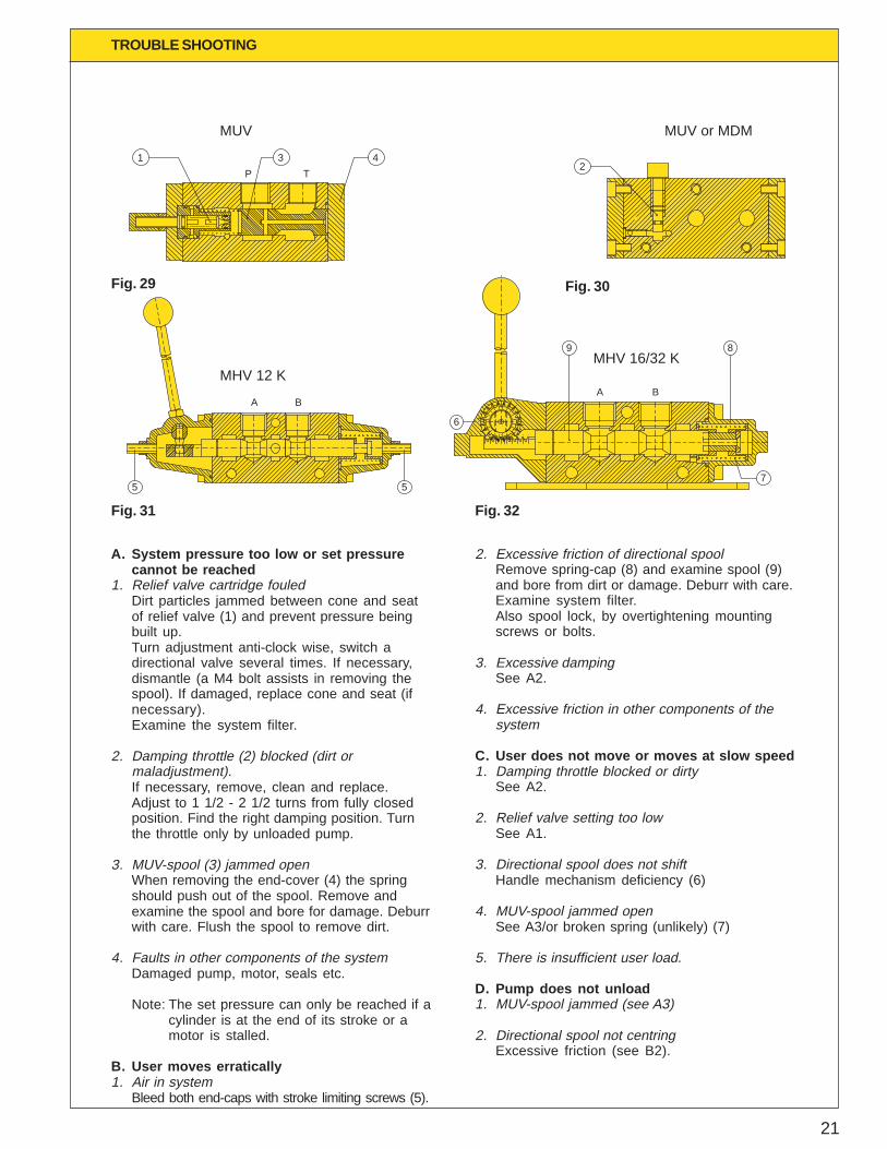
A. System pressure too low or set pressurecannot be reached
1. Relief valve cartridge fouledDirt particles jammed between cone and seatof relief valve (1) and prevent pressure beingbuilt up.Turn adjustment anti-clock wise, switch adirectional valve several times. If necessary,dismantle (a M4 bolt assists in removing thespool). If damaged, replace cone and seat (ifnecessary).Examine the system filter.
2. Damping throttle (2) blocked (dirt ormaladjustment).If necessary, remove, clean and replace.Adjust to 1 1/2 - 2 1/2 turns from fully closedposition. Find the right damping position. Turnthe throttle only by unloaded pump.
3. MUV-spool (3) jammed openWhen removing the end-cover (4) the springshould push out of the spool. Remove andexamine the spool and bore for damage. Deburrwith care. Flush the spool to remove dirt.
4. Faults in other components of the systemDamaged pump, motor, seals etc.
Note: The set pressure can only be reached if acylinder is at the end of its stroke or amotor is stalled.
B. User moves erratically1. Air in system
Bleed both end-caps with stroke limiting screws (5).
2. Excessive friction of directional spoolRemove spring-cap (8) and examine spool (9)and bore from dirt or damage. Deburr with care.Examine system filter.Also spool lock, by overtightening mountingscrews or bolts.
3. Excessive dampingSee A2.
4. Excessive friction in other components of thesystem
C. User does not move or moves at slow speed1. Damping throttle blocked or dirty
See A2.
2. Relief valve setting too lowSee A1.
3. Directional spool does not shiftHandle mechanism deficiency (6)
4. MUV-spool jammed openSee A3/or broken spring (unlikely) (7)
5. There is insufficient user load.
D. Pump does not unload1. MUV-spool jammed (see A3)
2. Directional spool not centringExcessive friction (see B2).
Fig. 29 Fig. 30
Fig. 31 Fig. 32
22
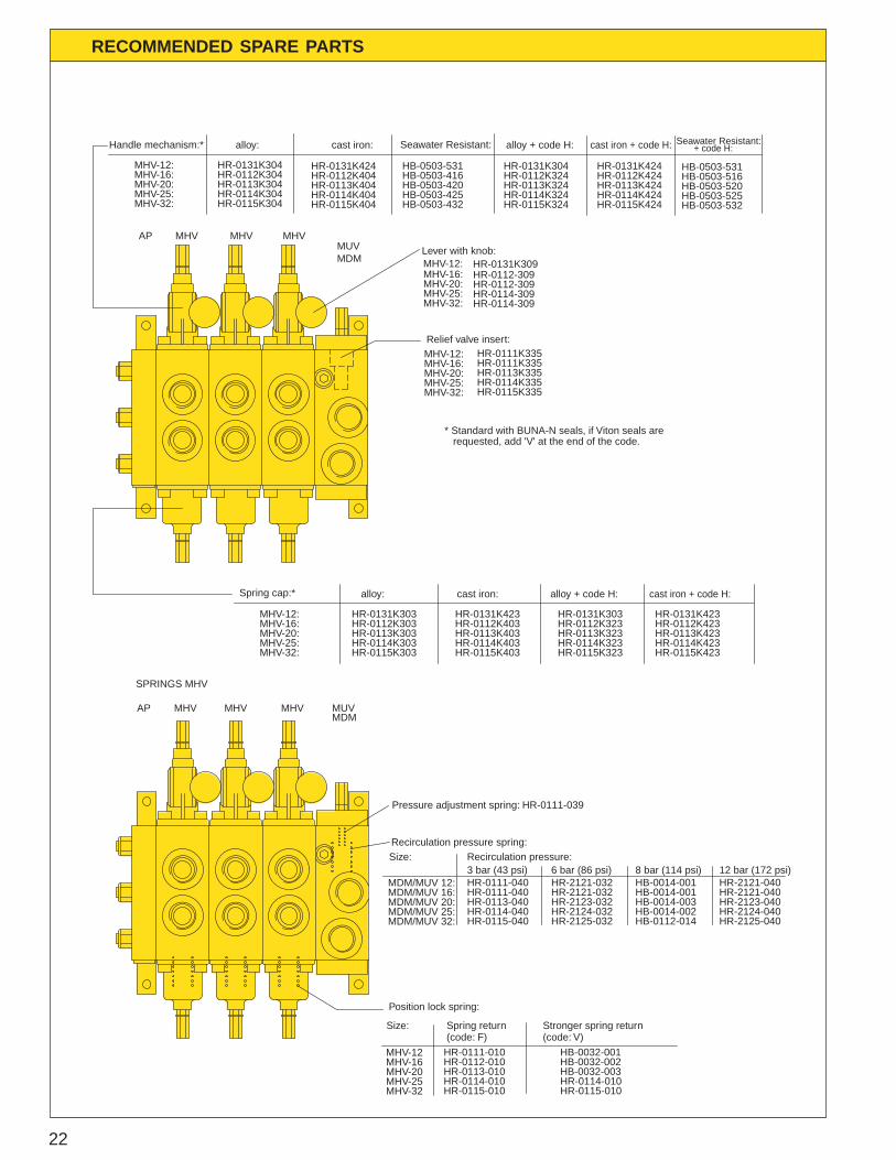
RECOMMENDED SPARE PARTS
HR-2121-040HR-2121-040HR-2123-040HR-2124-040HR-2125-040
cast iron + code H:
HR-0131K424HR-0112K424HR-0113K424HR-0114K424HR-0115K424
MHVAP MHV
SPRINGS MHV
MHV
HB-0014-003HR-2123-032MDM/MUV 20: HR-0113-040
Position lock spring:
HR-0113-010
HR-0115-010HR-0114-010
HR-0112-010HR-0111-010
HR-0114-040HR-0115-040
MHV-20
MHV-32MHV-25
MHV-16MHV-12
MDM/MUV 32:MDM/MUV 25:
HB-0032-003HR-0114-010HR-0115-010
HB-0032-001HB-0032-002
HR-2124-032HR-2125-032
HB-0014-002HB-0112-014
Recirculation pressure:
HR-0111-040HR-0111-040
Pressure adjustment spring: HR-0111-039
Recirculation pressure spring:
MDM/MUV 16:MDM/MUV 12:
Size:3 bar (43 psi)
MDMMUV
HR-2121-032HR-2121-032
6 bar (86 psi)HB-0014-001HB-0014-001
8 bar (114 psi)
alloy:
MHV-12:MHV-16:MHV-20:MHV-25:MHV-32:
AP
HR-0131K304HR-0112K304HR-0113K304HR-0114K304HR-0115K304
HR-0114-309HR-0112-309HR-0112-309
HR-0114-309
HR-0131K309
HR-0111K335HR-0111K335
HR-0114K335HR-0115K335
HR-0113K335
MHV-12:
MHV-25:MHV-20:MHV-16:
MHV-32:
Relief valve insert:
Lever with knob:
alloy + code H:cast iron:
HR-0131K424HR-0112K404HR-0113K404HR-0114K404HR-0115K404
HR-0131K304HR-0112K324HR-0113K324HR-0114K324HR-0115K324
12 bar (172 psi)
MHV MHV MHVMUVMDM
Handle mechanism:*
MHV-12:
MHV-25:MHV-20:MHV-16:
MHV-32:
MHV-16: HR-0112K303 HR-0112K403 HR-0112K323 HR-0112K423HR-0113K403HR-0114K403HR-0115K403
MHV-20:MHV-25:MHV-32: HR-0115K303
HR-0114K303HR-0113K303 HR-0113K323
HR-0114K323HR-0115K323 HR-0115K423
HR-0114K423HR-0113K423
cast iron:
HR-0131K423
Spring cap:*
MHV-12: HR-0131K303
alloy: alloy + code H:
HR-0131K303
cast iron + code H:
HR-0131K423
Size: Spring return Stronger spring return(code: V)(code: F)
HB-0503-531HB-0503-416HB-0503-420HB-0503-425HB-0503-432
Seawater Resistant:
HB-0503-531HB-0503-516HB-0503-520HB-0503-525HB-0503-532
Seawater Resistant: + code H:
* Standard with BUNA-N seals, if Viton seals are requested, add 'V' at the end of the code.
23
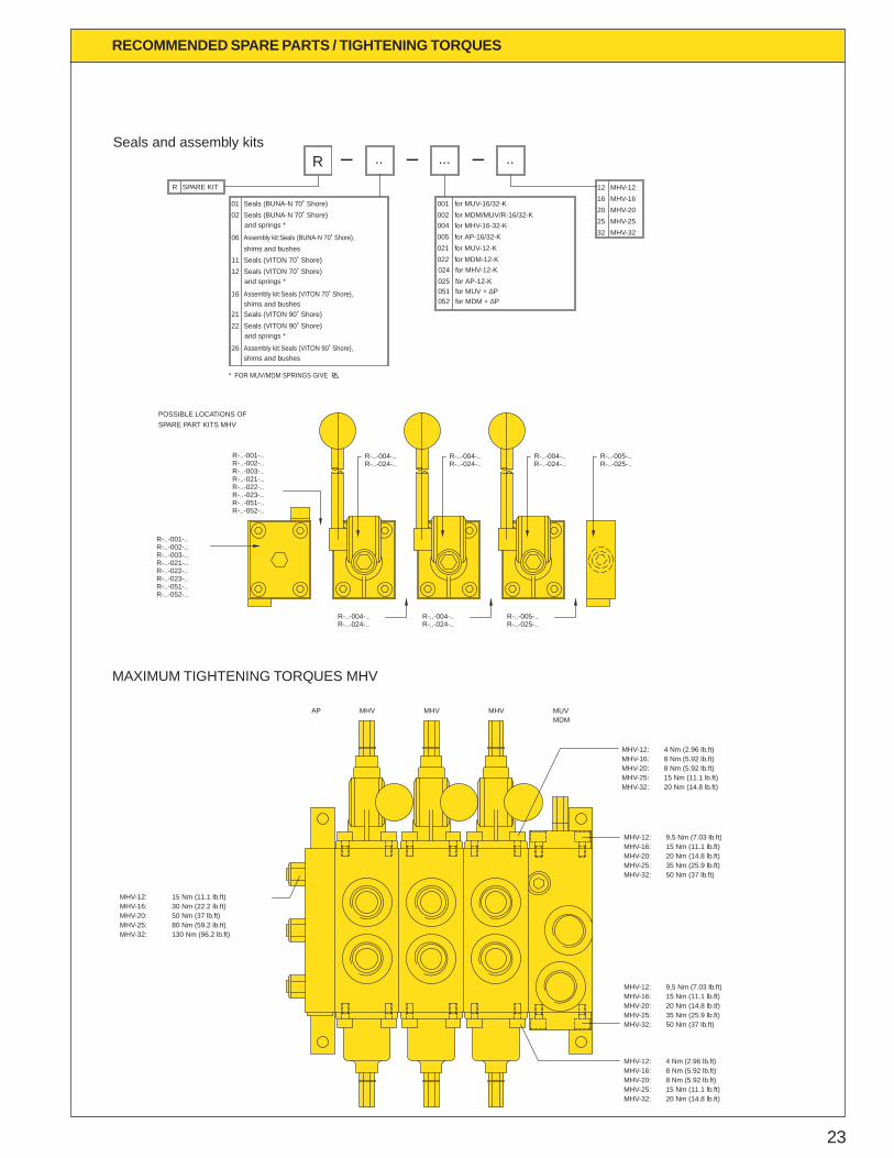
RECOMMENDED SPARE PARTS / TIGHTENING TORQUES
MAXIMUM TIGHTENING TORQUES MHV
130 Nm (96.2 lb.ft)80 Nm (59.2 lb.ft)50 Nm (37 lb.ft)30 Nm (22.2 lb.ft)15 Nm (11.1 lb.ft)
MHV-16:
MHV-25:MHV-20:
MHV-32:
MHV-12:
MHVAP MHV
4 Nm (2.96 lb.ft)8 Nm (5.92 lb.ft)8 Nm (5.92 lb.ft)15 Nm (11.1 lb.ft)20 Nm (14.8 lb.ft)
9,5 Nm (7.03 lb.ft)15 Nm (11.1 lb.ft)20 Nm (14.8 lb.tf)35 Nm (25.9 lb.ft)50 Nm (37 lb.ft)
9,5 Nm (7.03 lb.ft)
20 Nm (14.8 lb.ft)
50 Nm (37 lb.ft)35 Nm (25.9 lb.ft)
15 Nm (11.1 lb.ft)
MHV-16:MHV-12:
MHV-25:MHV-20:
MHV-32:
MHV-12:
MHV-20:
MHV-32:MHV-25:
MHV-16:
MHV-16:MHV-20:
MHV-12:
MHV-32:MHV-25:
4 Nm (2.96 lb.ft)8 Nm (5.92 lb.ft)8 Nm (5.92 lb.ft)15 Nm (11.1 lb.ft)20 Nm (14.8 lb.ft)
MDMMHV MUV
MHV-20:
MHV-32:MHV-25:
MHV-12:MHV-16:
R-..-001-..R-..-002-..R-..-003-..R-..-021-..R-..-022-..R-..-023-..
R-..-052-..R-..-051-..
shims and bushes for MDM + ∆Pfor MUV + ∆P
for MHV-16-32-K
for MDM-12-Kfor MUV-12-K
for MDM/MUV/R-16/32-K
for AP-16/32-K
for MUV-16/32-K
for AP-12-Kfor MHV-12-K
051052
025024022
* FOR MUV/MDM SPRINGS GIVE P
shims and bushesAssembly kit:Seals (VITON 90˚ Shore),
Seals (VITON 90˚ Shore)Seals (VITON 90˚ Shore)
26
2221
005021
004002001
and springs *
Assembly kit:Seals (BUNA-N 70˚ Shore),
Seals and assembly kits
SPARE KIT
shims and bushes
Assembly kit:Seals (VITON 70˚ Shore),
Seals (VITON 70˚ Shore)Seals (VITON 70˚ Shore)
Seals (BUNA-N 70˚ Shore)Seals (BUNA-N 70˚ Shore)
06
12
16
11
0102
R
and springs *
and springs *
R ..
POSSIBLE LOCATIONS OF
25 MHV-2532 MHV-32
1612
20
MHV-12
MHV-20MHV-16
R-..-002-..
R-..-023-..R-..-051-..R-..-052-..
R-..-003-..R-..-021-..R-..-022-..
SPARE PART KITS MHV
R-..-001-..
... ..
R-..-025-..R-..-005-..R-..-004-..
R-..-024-..R-..-004-..R-..-024-..
R-..-004-..R-..-024-.. R-..-024-..
R-..-004-.. R-..-005-..R-..-025-..R-..-024-..
R-..-004-..
24
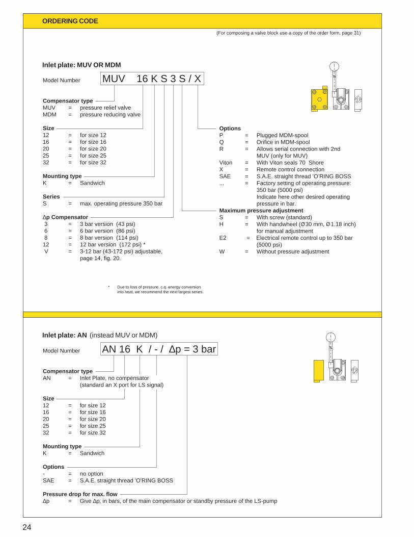
MUV 16 K S 3 S / X Model Number
Compensator typeMUV = pressure relief valve MDM = pressure reducing valve Size 12 = for size 1216 = for size 1620 = for size 2025 = for size 2532 = for size 32 Mounting type K = Sandwich
Series S = max. operating pressure 350 bar ∆p Compensator 3 = 3 bar version (43 psi) 6 = 6 bar version (86 psi) 8 = 8 bar version (114 psi)12 = 12 bar version (172 psi) * V = 3-12 bar (43-172 psi) adjustable,
page 14, fig. 20.
* Due to loss of pressure, c.q. energy conversion into heat, we recommend the next largest series.
Options P = Plugged MDM-spoolQ = Orifice in MDM-spool R = Allows serial connection with 2nd
MUV (only for MUV)Viton = With Viton seals 70 Shore X = Remote control connectionSAE = S.A.E. straight thread ’O’RING BOSS... = Factory setting of operating pressure:
350 bar (5000 psi) Indicate here other desired operating
pressure in bar.Maximum pressure adjustment S = With screw (standard) H = With handwheel ( 30 mm, 1.18 inch)
for manual adjustment E2 = Electrical remote control up to 350 bar (5000 psi)W = Without pressure adjustment
(For composing a valve block use a copy of the order form, page 31)
ORDERING CODE
Inlet plate: MUV OR MDM
AN 16 K / - / ∆p = 3 barModel Number
Compensator type AN = Inlet Plate, no compensator (standard an X port for LS signal) Size 12 = for size 1216 = for size 1620 = for size 2025 = for size 2532 = for size 32
Mounting type K = Sandwich
Options- = no optionSAE = S.A.E. straight thread 'O'RING BOSS
Pressure drop for max. flow∆p = Give ∆p, in bars, of the main compensator or standby pressure of the LS-pump
Inlet plate: AN (instead MUV or MDM)
25
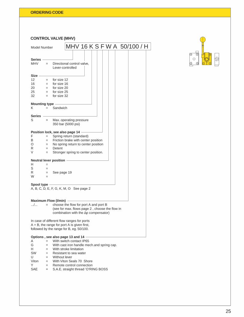
MHV 16 K S F W A 50/100 / HModel Number
Series MHV = Directional control valve, Lever-controlled
Size 12 = for size 1216 = for size 1620 = for size 2025 = for size 2532 = for size 32
Mounting type K = Sandwich Series S = Max. operating pressure 350 bar (5000 psi)
Position lock, see also page 14F = Spring return (standard)B = Friction brake with center positionO = No spring return to center positionR = DetentV = Stronger spring to center position.
Neutral lever positionH =S = R = See page 19 W = Spool type A, B, C, D, E, F, G, K, M, O See page 2
Maximum Flow (l/min).../... = choose the flow for port A and port B (see for max. flows page 2 , choose the flow in combination with the ∆p compensator)
In case of different flow ranges for ports A + B, the range for port A is given first,followed by the range for B, eg. 50/100.
Options , see also page 13 and 14A = With switch contact IP65G = With cast iron handle mech.and spring cap.H = With stroke limitationSW = Resistant to sea waterU = Without leverViton = With Viton Seals 70 Shore Y = Remote control connection SAE = S.A.E. straight thread ’O’RING BOSS
ORDERING CODE
CONTROL VALVE (MHV)
26
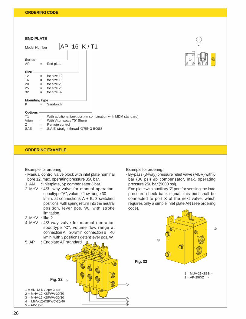
END PLATE
Example for ordering:- Manual control valve block with inlet plate nominalbore 12, max. operating pressure 350 bar.
1. AN : Inletplate, Dp compensator 3 bar.2. MHV : 4/3 -way valve for manual operation,
spooltype “A”, volume flow range 30l/min. at connections A + B, 3 switchedpositions, with spring return into the neutralposition, lever pos. W., with strokelimitation.
3. MHV : like 2.4. MHV : 4/3-way valve for manual operation
spooltype “C”, volume flow range atconnection A = 20 l/min, connection B = 40l/min, with 3 positions detent lever pos. W.
5. AP : Endplate AP standard
AP 16 K / T1 Model Number
SeriesAP = End plate
Size 12 = for size 1216 = for size 1620 = for size 2025 = for size 2532 = for size 32
Mounting type K = Sandwich
OptionsT1 = With additional tank port (in combination with MDM standard)Viton = With Viton seals 70˚ ShoreZ = Remote controlSAE = S.A.E. straight thread 'O'RING BOSS
5 BB
B
AA
4
T
32
1
P
X
2
T
P
Z 1
Example for ordering:- By-pass (3-way) pressure relief valve (MUV) with 6bar (86 psi) Dp compensator, max. operatingpressure 250 bar (5000 psi).
- End plate with auxiliary ‘Z’ port for sensing the loadpressure check back signal, this port shall beconnected to port X of the next valve, whichrequires only a simple inlet plate AN (see orderingcode).
1 = AN-12-K / Dp= 3 bar2 = MHV-12-KSFWA-30/303 = MHV-12-KSFWA-30/304 = MHV-12-KSRWC-20/405 = AP-12-K
Fig. 32
Fig. 33
1 = MUV-25KS6S >2 = AP-25K/Z >
ORDERING CODE
ORDERING EXAMPLE
27
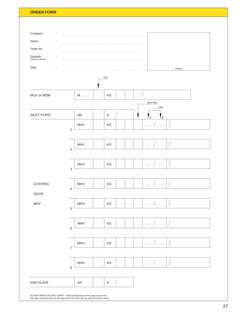
ORDER FORM
Company
Name
Order No.
Quantity(complete system)
Date :
:
:
:
:
(stamp)
MUV or MDM
INLET PLATE
M
AN
MHV1
2MHV
3MHV
4MHV
5MHV
6MHV
7MHV
8MHV
END PLATE AP
KS
K
KS
K
KS
KS
KS
KS
KS
KS
KS
MHV
VALVE
CONTROL
Size
Spool type
Flow
DO NOT WRITE ON THIS CHART - make a photocopy of this page and recordthe valve ordering code on the copy (then the chart can be used more than once)
. . . . . .
. .
. . . . . .
. . . . . .
. . . . . .
. . . . . .
. . . . . .
. . . . . .
. . . . . .
A B
Your local representative