Embed Size (px)
Citation preview
MI, Mineral InsulatedPipe Heating Cable, Installation & Maintenance Manual
P-116-2B
C O R P.
02/26/15


TABLE OF CONTENTS
Phone: (800) 324-1551 Fax: (918) 251-6079 www.trasor.com Page 3
General Information ................................................................................................................... 4
Receipt and Storage .................................................................................................................. 4
Heater Construction and Operation ........................................................................................... 5
Heater Operation, Variables and Formulas ................................................................................ 5
Heater Forms ............................................................................................................................. 6
Heater Part Numbers and Special Features .............................................................................. 7
Heater Connections ............................................................................................................. 8 & 9
Heater Testing .......................................................................................................................... 10
Installation Guidelines and Tips ................................................................................................ 11
Tools for Installation .................................................................................................................. 11
General Installation ..........................................................................................................12 & 13
Installation Details ........................................................................................................... 14 to 19
Heat Sink Adder Table ............................................................................................................. 20
Trouble Shooting ............................................................................................................. 21 & 22
Terms and Definitions .............................................................................................................. 23
Heater Installation and Inspection Log .................................................................................... 24
Heater Maintenance and Inspection Log ................................................................................. 25

GENERAL INFORMATION
Phone: (800) 324-1551 Fax: (918) 251-6079 www.trasor.com Page 4
General Information:This installation manual is for use with Trasor Mineral Insulated (MI) heat tracing systems installed on metal pipes and piping components.
Since 1969, Trasor has been building safe and dependable heat tracing systems. A safe and reliable heat tracing system requires quality products, proper design, installation and maintenance. Please carefully follow these detailed instructions and do not hesitate to contact the factory or your local representative.
Trasor Corporation P.O. Box 470522 Tulsa, OK, 74147, USA Tel (800) 324-1551 Fax (918) 251-6079 [email protected] www.trasor.com
Electric Heat Trace Systems:Electric heat trace systems replace the heat that is lost through the thermal insulation. One or multiple electric resistive elements trace the length of the pipe. This allows the pipe to be maintained at a specific temperature. Freeze protection systems are designed to prevent the pipe from freezing, such as water or steam lines. Process heating systems are designed to maintain contents of a pipe at elevated temperatures, such as wax, caustics or asphalt.
Important:All information contained in this manual is believed to be accurate and reliable. Users should independently evaluate this information for suitability for their particular application. Trasor Corporation makes no warranties as to the accuracy or completeness of the information, and disclaims any liability regarding its use. Trasor Corporations' only obligations are those such expressed in the sale of the particular product. In no case will Trasor Corporation be liable for any incidental, indirect, or consequential damages arising from the sale, resale, use or misuse of the product.
Electrical Codes:Articles 427 and 500 of the National Electrical Code govern the installation of electric heat tracing systems in hazardous and non-hazardous areas. Installation of heat tracing system must comply will all national and local codes. Ground fault equipment protection is required for all pipe heating systems to prevent arching, fire, and shock if the cable is damaged or improperly installed.
Controls and Accessories:All related controls and associated components must be properly rated and approved for the area and application.
Controls should carry UL# XAPX or QUYX certification for non-hazardous areas and XBDV or QUZW for Hazardous areas.
Receiving and Storage:Compare all received materials against the packing list. Verify that no items have been damaged. It is recommended to field test all MI heaters as shown on page 10 and complete the heater installation and inspection record on page 24. Do not remove any tagging information. Store all materials in a clean dry area protected from weather and mechanical abuse.
Maintenance:Heater, junction boxes, control system and insulation sealing should be inspected annually. Follow the procedures in Heater Maintenance & Inspection Log on page 24.

Cold Lead
Hot to ColdJoint End Cap
TerminationGland Fitting
Pigtails
General Heater Construction
Internal View
HEATER CONSTRUCTION AND OPERATION
Phone: (800) 324-1551 Fax: (918) 251-6079 www.trasor.com Page 5
V Voltage = I * R
I Current = V ÷ R
W Wattage = V * I = I ² * R = V² ÷ R
w/ft Watts per foot = W ÷ L = I² * Ω/ft
R Resistance = L * Ω/ft = V ÷ I
L Heater length = R ÷ Ω/ft
Ω/ft Published heater resistance ≈ R ÷ L
Variables and Formulas:
Copper Conductors Resistive Conductors
SupplyVoltage
V
Figure 1
Figure 2
Heater Output (w/ft)
Hot Section
Note, Form “A” two conductor heater is shown in the above figures. There is also form “B” and “C” heaters. See page 6.
General Operation:MI heating cable is a series resistance heater that has a constant output along the entire length of the heater. It’s operation is consistent with Ohm’s Law.

HEATER FORMS
Phone: (800) 324-1551 Fax: (918) 251-6079 www.trasor.com Page 6
Cold Lead
Form ATwo Conductor
Cold Lead
Cold Lead
Hot Section
Hot Section Cold Lead
Hot Section Cold Lead
Heater Forms:
Form BTwo Conductor
Form BOne Conductor
End Cap
Cold Lead
Hot Section (Loop)
Form COne Conductor
Termination Gland ½” NPT Standard
Hot to Cold Joint PigtailsFigure 3
Figure 4
Figure 5
Figure 6

HEATER PART NUMBER SYSTEM
MISS-K752-AN-105-07-U2Special features (See table 1)
Cold Lead Length (ft), form “B” heaters specify two lengths
Heater length (ft)
Heating cable reference (See Cable Data Sheet)
Heater form (See page 6)
Heater Catalog Number System:
Phone: (800) 324-1551 Fax: (918) 251-6079 www.trasor.com Page 7
Table 1
Type Description
U2 E
R
Q
C1C2
PT
Special Features:
E
R
Q
C1C2
T
C1 ½” NPT reversed brass gland on hot to cold joint C2 3/4” NPT reversed brass gland on hot to cold joint E Puller eye end cap (form A only) P High Density Polyethylene jacketed cold lead Q High temperature adaptor R Reel mounted on non-returnable reel T** Extended pigtail length (** Tail length in ft) U2 Div 2 termination gland fitting X Special feature, specify
Cold Lead Length
Form ATwo Conductor
Cold Lead Length
Cold Lead Length
Cold Lead Length
Hot Section Length
Hot Section Length Cold Lead Length
Hot Section Length Cold Lead Length
Hot Section Length
Form BTwo Conductor
Form BOne Conductor
Form COne Conductor
End Cap
Cold Termination w/ ½” NPT GlandConnector
Hot to Cold Joint 11” Pigtails
MI heating cable, stainless steel sheath (Alloy 825)

HEATER CONNECTIONS
Phone: (800) 324-1551 Fax: (918) 251-6079 www.trasor.com Page 8
L1L2 / N
L1L2L3
L1
L2
L3N
Single phase
Single phase parallel
Three phase delta
Three phase wye, with neutral
Single phase, (one conductor)
Three phase wye, (one conductor)
Figure 7
Figure 8
Figure 9
Figure 10
Figure 11
Figure 12
NOTE: Ground fault equipment protection or monitoring is required for all pipe heating systems.
Typical connection configurations:
L1L2 / N
L1
L2 / N
L1
L2
L3
HEATER CONNECTIONS
Phone: (800) 324-1551 Fax: (918) 251-6079 www.trasor.com Page 9
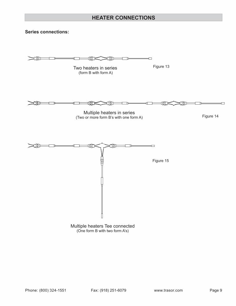
Series connections:
Figure 13
Multiple heaters in series(Two or more form B’s with one form A)
Two heaters in series (form B with form A)
Multiple heaters Tee connected(One form B with two form A’s)
Figure 15
Figure 14

HEATER TESTING
Phone: (800) 324-1551 Fax: (918) 251-6079 www.trasor.com Page 10
Hot-Cold Joint
IMPORTANT:If heater is installed, tests should be conducted with all power disconnected to the circuit. Test must be conducted with heater pigtails removed from terminal blocks or feed wiring.
Figure 16
Figure 17
Heater Insulation Resistance (Megger) Test:Use 500Vdc or 1000Vdc Megohmmeter (megger). Connect one lead to a pigtail and the other lead to the cold lead sheath or cold lead termination. Field readings should be above 200 Megohms. Low readings could indicate damage or break in the sheath.
Insulation resistance tests should be done throughout the installation as follows:
1) When it is received. 2) Prior to installing. 3) After it has been installed and prior to insulating pipe. 4) After thermal insulation is installed. 5) At time of commissioning.
Note: Meggers operate at high voltage. This voltage can be hazardous. Read and follow all instructions included with the instrument.
Testing:The following tests are important to verify the integrity of the heater throughout the installation. Use copies of the Inspection Log on page 24 to record these values for each heater. An annual inspection and maintenance log is provided on page 25.
Heater Resistance and Continuity Test:Use multi meter to check resistance and continuity of heater. Connect one lead on each pigtail of the heater.
Resistance and continuity test should be done throughout the installation as follows:
1) When it is received. 2) Prior to installing. 3) After it has been installed and prior to insulating pipe. 4) After thermal insulation is installed. 5) At time of commissioning.
Conductor resistance should be within 10% of the rated value.
Pigtail
Termination gland fittingCold lead terminationCold Lead

INSTALLATION GUIDELINES
Phone: (800) 324-1551 Fax: (918) 251-6079 www.trasor.com Page 11
Tools for installation:Leather GlovesScrew DriverLineman PliersAdjustable WrenchSoft Rubber or Wooden Mallet
General Installation Guidelines: 1. Follow all installation and layout drawings. Verify
actual pipe routing and piping dimensions are consistent with the drawings.
2. Unpack and test all heaters to verify there was no damage during shipping. Reference testing procedures on page 10 and record values in table 3 on page 24. Make copies of table 3 for each heater. Test heaters again before installation, after they are secured to the pipe (prior to the thermal insulation is applied), after the thermal insulation is complete, and at time of commissioning.
2. Prior to heater installation, review piping system and plan routing of cable. Consider all heat sinks valves, flanges, supports etc.
3. The cold lead termination and pigtails must be kept dry and protected from the weather before, during and after installation.
4. Minimum bending radius of heating cable is 6 x the cable diameter.
5. Handle hot to cold joint carefully. Support both sides when moving and positioning cold lead.
6. Do not bend the cable within 3” of any hot to cold joint, termination or splice joint.
7. Do not repeatedly bend and straighten cable. Cable can be work harden and break. See detail 22 on page 19 for straightening cable.
8. Do not over tighten banding or pipe straps when securing heating cable. They should only be snug to allow for expansion and contraction.
9. Do not install cable so that it may touch or overlap. This is important in hazardous areas.
10. Do not pull cable from center of coil into a spiral. Uncoil heater along the length of the pipe.
11. When installing cable on heat sinks such as pumps, valves, strainer, etc apply cable so that it can be easily removed with minimal bending if the equipment is serviced.
12. Hand form cable on heat sinks. A soft rubber or wooden mallet may be used to help conform cable to the heat sinks. Note, on valves and flanges it is not possible to have complete contact of the heating
cable and the object. Small gaps are okay. Fill gaps larger 1” with foil.
13. When adding cable to heat sinks use lengths provided on project drawings. When project drawings are not provided, use adder lengths in table 2, page 20.
14. Any excess heating cable must be distributed evenly along pipe or on heat sinks such as valves, flanges and supports.
15. Heating cables can not be randomly switched. Heating cables are design for a specific application based on several variables such as voltage, wattage, pipe size and maintenance temperatures.
16. Leave all tags on heating cables. They contain valuable electrical data, part numbers and approvals.
17. Protect heating cable from welding. Weld slag can burn small holes in heating cable. When welding, keep ground clamp close to weld area.
18. Junction boxes and entries must be properly sealed to prevent moisture entry. Install breather and drains at junction boxes and controllers.
19. If heater sheath or joint is cracked or broken, seal exposed areas with silicon until repair can be made. Do not energize damaged heater.
20. Some installations require heat transfer aids such as foil tape or heat transfer cement. Follow details 19 & 21 on pages 20 & 21 respectively.
21. IMPORTANT: The termination gland fitting is the grounding mechanism for the heater. This must be connect by an NEC approved grounding method.
22. Junction boxes and enclosures for electrical connections to the heating cable must be listed and approved for the environment in which they are installed.

Phone: (800) 324-1551 Fax: (918) 251-6079 www.trasor.com Page 12
1. Hot-Cold Joint, Detail 2, 3 & 4
2. Heater Termination, Detail 5 & 24
3. Flanged Valve, Detail 7
4. Shoe Support, Detail 10
5. Drain, Detail 16
6. Gauge, Detail 15
7. Flange Pair, Detail 13
8. Welded Valve, Detail 8
9. Blind Flange, Detail 14
5
314 7 9
8
6
2
GENERAL INSTALLATION
Figure 18
Step 1: Secure the hot to cold joint, (Reference Details 2, 3 & 4). Do not band within three inches of this joint. When possible, uncoil the heating cable and lay it alongside the pipe. If pipe mounted junction box or controller is used, secure it before securing the hot-cold joint.
Step 2:Temporarily secure the heating cable to the pipe approximately every ten feet, starting at the hot-cold joint and working towards the end of the pipe. Provide a loop of heating cable of the proper length at each heat sink, (valves, supports, etc), reference adder table 1, page 20. Redistribute any excess cable at heat sinks or uniformly along the length of the pipe.
Step 3:Form cable at heat sinks as shown in the installation details on the following pages. Do not overlap cable or allow it to touch itself. Avoid sharp bends and maintain a minimum bending radius of 6 times the cable diameter.
Step 4:Secure entire cable length with pipe straps, bands or tie wire every twelve to eighteen inches. Test heating cable and terminate into junction box or controller.
Installation Steps:

Phone: (800) 324-1551 Fax: (918) 251-6079 www.trasor.com Page 13
GENERAL INSTALLATION
Step 1
Step 2
Step 3
Step 4
Figure 19
Figure 20
Figure 21
Figure 22

Notes:
Typical installation of an MI heating cable when process temperatures are less than 300°F.
Secure the hot to cold joint as shown. Do not band within three inches of joint.
Exit the cold section at the bottom of the pipe to prevent moisture penetration.
Pipe
Insulation
Hot to Cold Joint
3”
Terminate to junction box or controller.
Trace Orientation
Phone: (800) 324-1551 Fax: (918) 251-6079 www.trasor.com Page 14
INSTALLATION DETAILS
Hot-Cold Joint on Pipe
Hot-Cold Joint Outside Insulation
Hot-Cold Joint
Notes:
This is a typical installation for MI cable on a high temperature freeze protection application, when the process temperatures are greater than 300ºF.
Use a high temperature adapter when heater wattage is greater than 20 watts/heater foot. See Detail 3.
Hot to Cold Joint
Terminate to junction boxor controller.
1” +/-
Pipe
Heating Cable
12” to 18” Spacing Secure with pipe straps,
Bands or tie wire.
Pipe
Double TraceSingle TraceTemperature
Sensor
Pipe Straps, Banding or Tie wire
Triple trace
Heating Cable
Notes:
It is typically easier to install heating cable on the top of the pipe. There is minimal gain in efficiency installing the cable on the bottom of the pipe.
Keep 90° separation between heating cable and temperature sensor.
Detail 1 Detail 2
Detail 3 Detail 4
Cold Lead
Cold Lead
Heating Cable
Secure with pipe straps, bands or tie wire.
Pipe
Insulation
Heating Cable
Secure with pipe straps, bands or tie wire.
Proprietary Information Proprietary Information
Proprietary Information
High Temperature Adapter
Terminate to junction boxor controller.
High Temperature Adapter
IMPORTANT: Be carful not to spin or twist Cold Lead when tightening adaptor compression fitting.
Optional method if aboveis not conducive.
Cold Lead
Notes:High temperature adapters should be used to isolate the hot to cold joint from process temperatures greater than 300°F.
Secure the adapter so that it exits the bottom side of the pipe.
Pipe
Insulation
Heating Cable
Secure with pipe straps, bands or tie wire.
Proprietary Information
Hot to Cold Joint

Phone: (800) 324-1551 Fax: (918) 251-6079 www.trasor.com Page 15
INSTALLATION DETAILS
Power
Junction Box, shownwith pipe mount bracket
Cold Lead
HeatingCable
Secure with pipe straps, bands or tie wire
Adder length from Table 2, Page 20
Pipe
Notes:
Extra cable is added on valves to compensate for greater heat loss. The amount of cable applied is equal to the flange to flange distance plus the value shown in Table 2, Page 20. On projects always follow manufactures drawings for adders.
Heating Cable
Pipe
Pipe
Heating Cable Secure with pipe straps, bands, tape or tie wire.
Temperature Sensor
Pipe Straps, Banding, Tape or Tie Wire
Heating Cable
Notes:
Locate temperature sensor within the heated zone. Keep away from heat sinks such as supports and valves.
Keep at least 90° separation between heating cable and temperature sensor.
Secure for good thermal contact with pipe. Do not crush or damage sensor as to cause calibration error.
Exit sensor lead at bottom of pipe to prevent moisture entry
Detail 5 Detail 6
Welded or Screwed Valve
Detail 8
welded or screwed valve
Detail 7
Adder length from Table 2, Page 20
Notes:
Extra cable is added on valves to compensate for greater heat loss. The amount of cable applied is equal to the length of the valve the value shown in Table 2, Page 20. On projects always follow manufactures drawings for adders.
Large Flanged Valve
Junction Box on Pipe Temperature Sensor Location
Notes:
Locate junction box within reach of the cold lead termination.
Do not cross cable with pipe straps used to mount junction box bracket. Tension is much greater than what should be used on heating cable.
Secure with pipe straps, bands or tie wire.
Wrap with tie wire
Heating Cable
Wrap with tie wire Flanged valve
Secure with pipe straps, bands or tie wire.
Proprietary Information Proprietary Information
Proprietary Information Proprietary Information
Notes:
Locate temperature sensor within the heated zone. Keep away from heat sinks such as supports and valves.
Keep at least 90° separation between heating cable and temperature sensor.
Secure for good thermal contact with pipe. Do not crush or damage sensor as to cause calibration error.
Notes:
Locate junction box within reach of the cold lead termination.
Do not cross cable with pipe straps used to mount junction box bracket. Tension is much greater than what should be used on heating cable.
Secure with pipe straps or banding
Pipe
Pipe
Lightly secure sensing bulb with pipe straps, bands, tie wire or tape

Phone: (800) 324-1551 Fax: (918) 251-6079 www.trasor.com Page 16
INSTALLATION DETAILS
Heating Cable
Pipe
Notes:
Extra cable is added on valves to compensate for greater heat loss. The amount of cable applied is equal to the flange to flange distance plus the value shown in Table 2, Page 20. On projects always follow manufactures drawings for adders.
Notes:
Extra cable is added at supports to compensate for greater heat loss. The amount of cable applied is equal to the support length plus the value shown in Table 2, Page 20. On projects always follow manufactures drawings for adders.
Shoe Support
Secure with pipe straps, bands or
Notes:
Extra cable is added at hangers to compensate for greater heat loss. The amount of cable applied is equal to the value shown in Table 2, Page 20. On projects always follow manufactures drawings for adders.
Notes:
Extra cable is added at supports to compensate for greater heat loss. The amount of cable applied is equal to the value shown in Table 2, Page 20. On projects always follow manufactures drawings for adders.
Secure with pipe straps, bands or tie wire.
Detail 9 Detail 10
Detail 11 Detail 12
Dummy Leg SupportHanger Support
Butterfly Valve Shoe Support
Adder length from Table 2, Page 20
Adder length from Table 2, Page 20
Heating Cable
Pipe
Secure with pipe straps, bands or
Butterfly Valve
Adder length from Table 2, Page 20
Heating Cable
Pipe
Dummy LegSupport
Secure with pipe straps, bands or tie wire.
Adder length from Table 2, Page 20
Heating Cable
Pipe
Proprietary Information Proprietary Information
Proprietary Information Proprietary Information

Phone: (800) 324-1551 Fax: (918) 251-6079 www.trasor.com Page 17
INSTALLATION DETAILS
Notes:
Extra cable is added on flanges to compensate for greater heat loss. The amount of cable applied is equal to the length of the valve the value shown in Table 2, Page 20. On projects always follow manufactures drawings for adders.
Notes:
Extra cable is added on blind flanges to compensate for greater heat loss. The amount of cable applied is equal to the length of the valve the value shown in Table 2, Page 20. On projects always follow manufactures drawings for adders.
GENERAL:Extra cable is applied on pressure gauges and vents to compensate for heat loss.
Secure with pipe straps, bands or tie wire.
PipeHeating Cable
Secure with pipe straps, bands or tie wire.
PipeHeating Cable
Detail 13 Detail 14
Detail 15 Detail 16
Drain ValveGauges and Vents
Flange Pair Blind Flange
Adder length from Table 2, Page 20
Heating Cable
Pipe
Flange Pair
Secure with pipe straps, bands or tie wire.
Adder length from Table 2, Page 20
Heating Cable
Pipe
Blind Flange
Secure with pipe straps, bands or tie wire.
Notes:
Extra cable is added on gauges and vents to compensate for greater heat loss. Follow project drawings for adder length.
Notes:
Extra cable is added on drains to compensate for greater heat loss. Follow project drawings for adder length.
Adder length
Adder length
Proprietary Information Proprietary Information
Proprietary Information Proprietary Information

Phone: (800) 324-1551 Fax: (918) 251-6079 www.trasor.com Page 18
INSTALLATION DETAILS
Notes:Install cold lead at bottom of pump. Secure heating cable with tie wire or banding.
Cold Lead
Heating Cable
Heating Cable
Pump
Secure with Tie wire or Banding
Heating Cable
Cover heating cable with Heat
Transfer Foil tape.
Pipe
Detail 17 Detail 18
Detail 19 Detail 20
Heat Transfer Foil
Strainer Pump
Adder length
Notes:
Extra cable is added on strainers to compensate for greater heat loss. On projects always follow manufactures drawings for adders.
Notes:
Heat transfer foil tape should be used when a soft pipe insulation such as fiberglass is used. The foil will prevent the cable from being encapsulated in insulation.
Heat transfer foil is also used to enhance heat transfer and reduce sheath temperatures.
Secure with pipe straps, bands or tie wire.
Heating Cable
Pipe
Strainer
Secure with pipe straps, bands or tie wire.
Proprietary Information Proprietary Information
Proprietary Information
Spacer Strip
Heating Cable
Bend tabs over to hold cable in place.
1” Tab spacing
Notes: Spacer strip is used to hold heating cable at uniform spacing on flat surfaces, large pipes or vessel walls. The strip can be welded to the surface or held in place with banding or weld studs.
½”
Spacer Strip
Proprietary Information
Heating Cable

Phone: (800) 324-1551 Fax: (918) 251-6079 www.trasor.com Page 19
INSTALLATION DETAILS
Pipe
Heat Transfer Cement
Heating Cable
Straightening 180º Bends
Straightening 90º Bends
R Cable Diameter
R = 6 x Cable diameter, recommended minimum bending radius.
Notes:When reforming MI heating cable, it is important to not to overwork heating cable.
Bends should be reformed as shown. Leave major bends as small wiggles. These small bends will not affect the performance of the cable.
Excessive bending will work harden the cable. The cable can crack when overworked. Consult factory if a cable cracks or breaks.
Detail 21 Detail 22
Thermostat InstallationTie Wire
Heat Transfer Cement Straightening MI Cable
Detail 23 Detail 24
Proprietary Information Proprietary Information
Proprietary Information Proprietary Information
Secure with pipe straps, bands or tie wire.
Notes:
Heat transfer cement is used to enhance heat transfer and significantly reduces sheath temperatures. It is often used on high wattage heaters or heat up applications.
Pipe surface must be clean prior to application of cement. Remove all loose paint, grease, and oil.
After heater is secured in place, apply generous portions of cement to both sides of cable as shown. Fill all voids.
Wet tools with water for smoother application.
Before insulating, allow cement to cure at least 24 to 48 hours or until cement is rock hard.
Notes:
Hairpin ties provide maximum strength. Pre-cut ties to length. Length is equal to 2 x pipe circumference + 12”.
Secure heating cable every 12” to 18”.
Twist tie until cable is held in place.
Cut of excess wire and fold over the remaining nub to prevent cut hazard.
Heating Cable
Bulk tie wire
Pipe
Completed tie
Coil extra capillary under thermostat
Power
DrainHeating Cable
Lightly secure sensing bulb with pipe straps, bands, tie wire or tape
Thermostat, shown with pipe mounting bracket
Notes:
Locate temperature sensor within the heated zone. Keep away from heat sinks such as supports and valves.
Keep at least 90° separation between heating cable and temperature sensor.
Do not cross cable with pipe straps used to mount junction box bracket. Tension is much greater than what should be used on heating cable.
Pipe
Secure with pipe straps or banding
Cold lead

Phone: (800) 324-1551 Fax: (918) 251-6079 www.trasor.com Page 20
1. The lengths above are the recommended amount of extra cable (Adder) to be added on these fittings to compensate for greater heat loss at these fittings. On projects always follow manufactures drawings for adders.
2. The total amount of cable applied to the fitting is equal to the value in the table plus the flange-to-flange distance of that fitting. (Eq: 4”Φ x 1’ long flanged valve will require a total of 4' of heating cable, 1’ for the valve length plus 3’ for the adder.).
3. If there are multiple traces, the total length is to be divided among the individual traces of cable. (Eq: 8”Φ x 1.5’ long flanged valve with two traces of cable will require a total of 11' of heating cable, 3’ for the length of the valve with two traces plus 8’ for the adder.).
4. For some applications, it may be physically impossible to install all of the recommended heating cable directly on the fitting or support. In this case, install the excess heating cable on either side of the fitting or support.
6. Values are based on average fitting sizes.
3’ Adder length, From table
4” Flanged Φ
1’ 4’ of Cable
Adder Example:
Figure 24Figure 23Total
INSTALLATION DETAILS
.5” 1 0.5 0.5 1 1 0.5 1
.75” 1.5 0.75 .5 1.5 1 0.5 1
1” 2 1 1 1.5 1 0.5 1
1.5” 2 1.5 1.5 1.5 1.5 0.5 1
2” 2.5 2 2 2 1.5 1 1.5
3” 3 2.5 2.5 2 2 1 1.5
4” 3 3 3 2.5 2 1 1.5
6” 6 5 3.5 3 3 1 2
8” 8 6 4 3 3 1.5 2
10” 9 6 4.5 3 3 1.5 3
12” 12 8 5 3 3 1.5 3
14” 12 8 5.5 3 3 1.5 3
16” 15 10 6 4 3 1.5 3
18” 18 10 6.5 4 4 1.5 3
20” 20 12 7 4 4 2 4
24” 24 14 8 4 4 2 4
Heat Sink Adder Lengths (ft.)
Table 2
Flanged Valve
Welded Valve
ButterflyValve
Shoe Support
HangerSupport
Flange(Pair)
Pipe Size(N.P.S.) Blind
Flange
Heat Sink Adder Table:
Actual fitting length

TROUBLE SHOOTING
Phone: (800) 324-1551 Fax: (918) 251-6079 www.trasor.com Page 21
A. Circuit breaker trips. 1. Circuit breaker under sized.
2. Defective circuit breaker.
3. Short circuit in feed wiring or circuit connections.
4. Moisture in connection box.
5. Damaged heating cable, nicks or cuts in sheath, kinked or crushed sheath, crack at termination or hot to cold joint.
6. Ground fault protection devise is undersized, less than 30mA. Devise may wired incorrectly.
1. Calculate total current load and resize breaker. Verify feed wiring is compatible for larger breaker.
2. Replace circuit breaker
3. Locate and repair faulty wiring or connections. Check with megger.
4. Dry all connections, check all entry seals and implement conduit drains.
5. Immediately seal brake or crack with silicon and consult factory for repair or replace heating cable.
6. Replace with 30 mA GFPD or adjust controller trip point value to 30 mA. Check wiring.
Symptoms: Possible Cause: Corrective Action:
B. No power output or power is lower than rated value.
1. Low or no input voltage.
2. Connection to temperature controller on normally open (NO) contact.
3. Improper crimping of power connections causing high resistance.
4. Heater may have been severed.
5. Wrong heater was used.
6. Pipe temperature is above the set point of the controller.
7. Some heating cables have significant resistance change at elevated temperatures.
1. Repair electrical supply or replace equipment.
2. Confirm connection to the temperature controller is on the normally closed (NC) contact. Contacts close when temperature drops.
3. Recrimp connection using proper procedure.
4. Repair or replace heater.
5. Replace with proper heater.
6. Heater should energize when pipe temperature drops below set point of controller.
7. Consult factory with heater and process information.
Symptoms: Possible Cause: Corrective Action:

TROUBLE SHOOTING
Phone: (800) 324-1551 Fax: (918) 251-6079 www.trasor.com Page 22
C. Power output appears to be correct but p ipe temperature is below design temperature.
1. Wet or missing insulation.
2. Insufficient amount of heating cable was applied on valves, supports and other heat sinks.
3. Temperature controller set point is incorrect.
4. Temperature sensor in wrong location.
5. Low product temperature entering pipe.
6. Different thermal insulation was used or insufficient thickness.
1. Remove wet insulation and replace with dry insulation and cover and seal with proper weather proofing.
2. Confirm compliance with system design. If it is only one heat sink an additional heater can be applied and wired in series with the existing heater. If there are multiple heat sinks, the heater will have to be replaced with a longer heater.
3. Reset temperature controller.
4. Sensor may be to close to heating cable or may be to close to heat sink. Relocate sensor. See page 15, detail 6.
5. Check product temperature entering pipe.
6. Modify as needed. Consult factory for recommendations.
Symptoms: Possible Cause: Corrective Action:
D. H e a t e r i n s u l a t i o n res is tance low, low megger reading.
1. Rainy or high humidity.
2. Crack at termination joint.
3. Crack at hot to cold joint.
4. Nick, cut or crack in sheath.
5. Physical damage causing direct short.
1. Dry tails and termination seal.
2. Seal crack with silicon and replace termination.
3. Seal crack with silicon and replace cold lead.
4. Visually check heating cable at valves, flanges, supports and other heat sinks for damage. Replace damaged section or replace heater.
5. Replace damaged section or replace heater.
Symptoms: Possible Cause: Corrective Action:

TERMS AND DEFINITIONS
Phone: (800) 324-1551 Fax: (918) 251-6079 www.trasor.com Page 23
Adder: Extra length of heating cable applied at heat sinks to compensate for addition heat loss.
Cold lead: Non-heating section of the heating cable that terminates heating section of the heater to the connection point. It is equivalent to extension cord.
Ground Fault: A condition when unsafe currents are passing from heater conductors or power wiring to ground, typically greater than 30 milliamps. Ground fault breakers or sensing devices are required on all pipe heating circuits.
Heat Loss: Energy lost to the environment from the pipe through the thermal insulation, typical units are in Watts/foot.
Heat Sink: Components of a piping system that draw extra heat away from pipe, such as valves, flanges, supports etc.. Extra heating cable must be added on these components to offset heat loss.
Hot Section: Segment of the heater that has resistive conductors that generate heat.
Hot to Cold Joint: The transition point of the heating cable where the resistive heat generating conductors are joined to copper non-heating conductors.
Megger: Megohmmeter, primary test instrument used to test MI heaters. Measures insulation resistance between heater conductors and sheath with 500 to 1000 Volt DC. Resistance values are in Megohms (1000 Ohms).
MI: Stands for Mineral Insulated heating cable, a series resistant constant wattage heating cable. The insulation between the conductors and the sheath is a pure inorganic mineral Magnesium Oxide (MgO).

HEATER INSTALLATION & INSPECTION LOG
Phone: (800) 324-1551 Fax: (918) 251-6079 www.trasor.com Page 24
Heater Catalog Number:
Tag or Circuit Number:
Line or Pipe Number:
Breaker / Panel Number:
Heater Design Resistance: ______ Ohms
Rating: ____Volts ____ Amps _____Watts
Heater Length: _____ Ft
Trasor Order Number, B- _____________
This document is used to track individual heater integrity throughout installation and checkout.
Contractor:
Client:
Comments:
1. Inspect heater for physical damage.
2. Heater resistance between conductors.
3. Insulation resistance between conductors and sheath.
Resistance should be within 10% of design value. See page 10, Figure 17.Use 500VDC megger, 200 megohms minimum. See page 10, Figure 16.Use megger or ohm meter to verify continuity. See page 10, Figure 17.
Pre Installation Testing:
Post Installation Testing (Before insulating pipe):
Final Testing and Commissioning:
Circuit Approval (Heater tested, documented and approved for service):
1. Thermal insulation complete and all penetrations properly sealed.
2. Insulation resistance between conductors and sheath.
3. Energized testing, Heater voltage
4. Energized testing, Heater current after 10 minutes
1. Inspect heater for physical damage.
2. Continuity between conductors.
3. Insulation resistance between conductors and sheath.
4. Cable properly installed on pipe.
5. Cable correctly installed on valves, supports and other heat sinks per system design.
6. Junction box or controller correctly installed and heater terminated.
1. Continuity between conductors.
2. Insulation resistance between conductors and sheath.
Thermal insulation complete:
1
2
3
2
3
2
1
2
3
2
Initial Date Values / Remarks 1. Inspect heater for physical damage.
2. Heater resistance between conductors.
3. Insulation resistance between conductors and sheath. 2
Testing at Time Heaters Received:
1

HEATER MAINTENANCE & INSPECTION LOG
Phone: (800) 324-1551 Fax: (918) 251-6079 www.trasor.com Page 25
Heater Catalog Number:
Tag or Circuit Number:
Line or Pipe Number:
Breaker / Panel Number:
Heater Design Resistance: ______ Ohms
Rating: ____Volts ____ Amps _____Watts
Heater Length: _____ Ft
Trasor Order Number, B- _____________
This document is used for periodic inspection.
Initial
Date
Thermal insulation free of damage, moisture, missing insulation or cladding.
Initial
Date
Water tight seals at valves, hangers, supports or any entries into the insulation.
Initial
Date
Inside connection box is clear of moisture and corrosion.
Initial
Date
Heater is properly connected and grounded at power connection.
Initial
Date
Test ground fault device for circuit.
Value
Initial
Date
Megger test between heater conductors and sheath with lead wires disconnected. (Megohms)
Heater Voltage at power connection.
Heater current after 5 minutes.
Initial
Date
All connection boxes and controllers have been properly sealed.
Set Pt.
Initial
Date
Controller checked for moisture, corrosion, set point, switch operation and sensor lead damage.
Value
Initial
Date
Value
Initial
Date
Use 500VDC megger, 200 megohms minimum. See page 10, figure 16. 1
1
Comments:
NOTES
Phone: (800) 324-1551 Fax: (918) 251-6079 www.trasor.com Page 26

NOTES
Phone: (800) 324-1551 Fax: (918) 251-6079 www.trasor.com Page 27

Phone: (800) 324-1551 Fax: (918) 251-6079 www.trasor.com