Embed Size (px)
Citation preview

1556-603X/10/$26.00©2010IEEE FEBRUARY 2011 | IEEE COMPUTATIONAL INTELLIGENCE MAGAZINE 55
Michael MargaliotTel Aviv University, Israel
Rami AbielmonaLarus Technologies, CANADA Emil M. PetriuUniversity of Ottawa, CANADA
Moufid Harb Larus Technologies, CANADA
Slawo WesolkowskiDRDC CORA, CANADA
Abstract–Territorial security deals with the prevention, detection and response to unauthorized persons and/or goods from crossing a perimeter. It deals with large territo-ries of strategic importance, such as international borders, transportation and critical infrastructure. Multi-agent systems provide flexibility, fault-tolerance, high sensing fidelity, low-cost and rapid deployment. In this paper, we concentrate on the challenges presented in applying the concepts of multi-agent systems to those presented by territorial security. We first introduce the overall system as well as prevalent agent architectures. We then briefly present our novel agent archi-tecture, its experimental embodiment and the virtualized reality model that accepts physical sensor data and updates a global model of the environment in real-time.
© BRAND X PICTURES
I. Introduction
P reventing, detecting, and responding to unauthorized
persons and/or goods crossing a perimeter is a security
concern of individual, corporate, and international
scope. State-of-the-art perimeter-security solutions use
physical barriers, sensors (indoor motion, cameras, audio/vibra-
tion), and human personnel (a camera operator, entrance guard,
and patrolling security guards). These procedures are effective
in a limited scenario, where a few entrance points are con-
strained by well-delineated physical boundaries.
Territorial security, however, deals with large territories of stra-
tegic importance, such as international borders, transportation
(airports, rail yards, public transit), and critical infrastructure (mili-
tary bases, nuclear facilities, emergency services, etc.) [1]. When
trying to monitor such large geographically-distributed
Mi ssion-Driven Robotic Intelligent Sensor Agents
for Territorial Security
Digital Object Identifier 10.1109/MCI.2010.939580
Date of publication: 17 January 2011
1556-603X/11/$26.00©2011IEEE FEBRUARY 2011 | IEEE COMPUTATIONAL INTELLIGENCE MAGAZINE 55

56 IEEE COMPUTATIONAL INTELLIGENCE MAGAZINE | FEBRUARY 2011
infrastructure, a number of challenges present themselves. First, a
linked network of this size is inflexible and expensive to setup.
Second, security operators frequently suffer from overload, stress,
and inattention due to the substantial influx of data. Finally, it is
increasingly important for territorial security systems to allow for
the sharing of knowledge to specified entities [2].
The complexity of securing an unpredictable and continu-
ously changing natural environment is a function of the nature,
number, and characteristics of the parameters of interest and of
the desired measurement data properties. The types of sensors,
their number and their bandwidth, their deployment in the
field, the expected performance levels of the sensor data acquisi-
tion system and of the data communication network are all
requirements that have to be considered when designing a multi-
agent system [3] for territorial security. Additionally, in order to
avoid wasting the limited power resources, the
agents should have a selective perception capa-
bility focusing only on the parameters that are
of interest for the specific securing task. Spe-
cially designed sensor planning strategies are
used to place the fixed and mobile sensor
agents in such a way as to get optimum performance during
specific tasks and for the real-time selection of sensing opera-
tions to minimize the observed system entropy [4].
A multi-agent system (MAS) is one where individual
agents coordinate their activities and cooperate with each
other, to avoid duplication of effort and to exploit other
agents’ capabilities [3]. Multi-agent systems have been pro-
posed and implemented for use in distributed sensing and
information retrieval and management [5]. A Distributed intelli-
gent sensor system (DISS) [6] was developed to integrate robotic
intelligent sensor agents (ISAs), the wireless communications
network, as well as the virtualized reality model of the environment
(VRME). ISAs could either be mobile (mISAs) or stationary
(sISAs). The virtualized reality concept introduced by Kanade
et al. [7] represents an extension of the typically computer-
generated, but synthetic virtual reality
concept. VRME integrates natural envi-
ronment information captured by the
ISAs in the field. DISS’ design require-
ments are broken up into five major cat-
egories (refer to Figure 1):
1) Distributed agent-based resource management: This framework pro-
vides a flexible, extensible and open
mechanism allowing for agent
interoperability. Work has already
been completed on such a framework
[8], that assumes a limited amount of
computational and communication
resources on each ISA;
2) Local intelligence: A reactive-
behavior paradigm [9] has been
investigated and implemented in
[10]. The agent reacts to sensory
inputs from its environment, by actu-
ating upon the latter, without rea-
soning about the performed actions.
A novel retroactive agent architecture has
been devised and tested in experi-
mental scenarios and will be present-
ed in this article;
3) Network intelligence: Since all
our ISAs are instinctive information
seeking agents, some of them will
cooperate together towards the
achievement of the overall goal, that
is to maximize the information
acquired from the environment
about objects or events;F IGURE 1 DISS flow diagram.
Distributed Agent-Based Management (1)
Agent
1
Agent
2
Agent
4
Agent
3
Agent
5
Agent
n
LI (2)
R-ISA Real-World Environment
LI–Local Intelligence
NI–Network Intelligence
Ethernet Access Points (EAPs)
Wireless Communication Network (InterRCom) (4)
Multi-Sensor Fusion (Centralized and Decentralized) (5)
Virtualized Reality Model of the Environment (VRME)
Ethernet (802.3)
NI (3)
Territorial security deals with large territories of strategic importance, such as international borders, transportation, and critical infrastructure.

FEBRUARY 2011 | IEEE COMPUTATIONAL INTELLIGENCE MAGAZINE 57
1) Wireless communication: A network
protocol, referred to as Intelligent Robotic
Communication (InteRCom), has been
devised to allow for the efficient utiliza-
tion of the available wireless channels;
and
2) Multi-sensor fusion: This mechanism
is used to integrate heterogeneous sen-
sory data into a composite and coherent model of the
environment. As human beings are valuable partners to
the ISAs to the degree that their capabilities comple-
ment those of the ISAs, the VRME should allow the
human operators to feel their own sense of vision, hear-
ing, smell, taste and touch. The latter can be accom-
plished by forcing a direct feeling of the contact
phenomena that a specific ISA experiences while in the
field [7]. However, we currently only support sensory
feedback to a workstation VRME. In the future, head-
mounted displays and haptic feedback gloves will allow
the human monitors to incrementally immerse them-
selves into the VRME.
Abielmona et al. have previously described an environment
mapping method called Tree-In-Motion Mapping (TIMM) that
combines environment mapping through entropy reduction
with a quadtree-based data structure to present a multi-
resolution and multi-dimensional view of the environment [6].
The method, which integrates simplicity and speed of compu-
tation, as well as low storage and communications require-
ments, is ideal for the targeted platform of fixed and mobile
agents. This article will concentrate on the local intelligence
and the VRME.
II. State of the ArtAs aforementioned, a MAS provides an effective solution to
distributed sensing applications. Shown in Table 1 is a com-
parison of the relevant MAS implementations, including
their agent architecture (AA) (i.e., R is a reactive one, P is a
proactive one, and H is a hybrid one), and the system’s most
prevalent pros and cons. In comparison with the systems pre-
sented above, DISS possesses a hybrid agent architecture, as
both reactive and retroactive agent architectures are utilized,
that provides system flexibility in choosing the best
architecture for particular applications. DISS clearly outlines
a communications protocol that allows for the agents to
communicate with system access points, as well as with each
other. The communication of incomplete results is performed
through a blackboard architecture, the latter being a major
component in synthesizing the global map from local
incomplete ones.
The agents are hardware independent, as the entire sys-
tem was specified using a hybrid formal specification lan-
guage, allowing for a level of abstraction that does not
constrain the designer to a particular architecture. This has
been demonstrated by the realization of three different
design implementations of the physical agents: a purely soft-
ware spin running on a microcontroller, a hardware/software
spin running on a programmable device (e.g. FPGA) and an
off-chip microcontroller, and finally, a hardware/software co-
design running on a programmable device and an on-chip,
soft-core microprocessor. Finally, DISS presents separate sim-
ulation and virtualization engines. The simulation engine
allows the user to simulate MAS-based scenarios to optimize
design factors while extracting environmental parameters.
Once the system has been optimized and realized, a separate
virtualization engine is used to seamlessly immerse the
remote user into the MAS environment, even across the
Internet, if required.
After reviewing the advantages and disadvantages of previ-
ous and related solutions, it was concluded that success within
an MAS was mainly achieved due to blackboard-based knowl-
edge sharing, odometric error correction, simulation engine
presence, and real-time mapping representation and searching
techniques [14]. Conversely, it was found that problems with
scalability, robustness and emergent behaviors resulted mainly
from static agent organizations, customized agent designs,
homogeneous agent architectures and incomplete results com-
munications [14].
TABLE 1 Comparison of MASes.
AUTHORS AA ADVANTAGES DISADVANTAGESLESSER AND ERMAN [11] H FOUNDATIONAL WORK IN DAI
TWO-TIERED BLACKBOARD ARCHITECTUREROBUST AND FAULT-TOLERANT SYSTEM
PRE-DESIGNED (STATIC) AGENT ORGANIZATIONSIMPRACTICALITY OF COMMUNICATING INCOMPLETE RESULTSHOMOGENEOUS AAS A HINDRANCE
PAULY AND KRAISS [12] H SUCCESSFUL QUADTREE AND AA* COMBINATIONEKF AIDS IN REDUCING ODOMETRIC ERRORSHYBRID AND FLEXIBLE AA
OVERBURDENING CUSTOMIZATION IN THE DESIGN OF AGENTSLACK OF EXPLICIT COMMUNICATIONS DETAILSHARDWARE-DEPENDENT AGENTS
DUDENHOEFFER AND BRUEMMER [13]
R ROBUST SIMULATION ENGINE IN SIMAGENTSOLID SOCIAL POTENTIAL FIELDS METHODONLINE LEARNING RESOLVED
CRUDE ROBOTIC POSENO SOLUTION TO RECURSIVE OR OMISSIVE SENSINGREACTIVE AA A DETRIMENT
The communication of incomplete results is performed through a blackboard architecture, the latter being a major component in synthesizing the global map from local incomplete ones.
58 IEEE COMPUTATIONAL INTELLIGENCE MAGAZINE | FEBRUARY 2011
III. Agent ArchitecturesAgent architectures define the approach that one takes in the
building of intelligent systems, including the internal structure
and operation of the agent. They are typically divided into
logic-based, reactive, belief-desire-intention and layered archi-
tectures. However, a more concrete division outlines proactive,
reactive and hybrid agent architectures. Proactive agent archi-
tectures are intuitive and easily decompose into subsystems;
however, they suffer from the problem of calculative rationality
and are usually difficult to realize [9]. Reactive agent architec-
tures are simple, economical and computationally tractable;
however they suffer from the problem of a short-term view
and are usually difficult to implement if they contain many
layers. Hybrid agent architectures are either horizontally-or
vertically-layered, and combine advantages from both proac-
tive and reactive architectures; however, they suffer from other
problems, such as the absence of a semantic or conceptual
clarity and the difficulty of inter-layer interactions. Other
techniques involving the evolution of the agent’s architecture
[15] are outside the scope of this article.
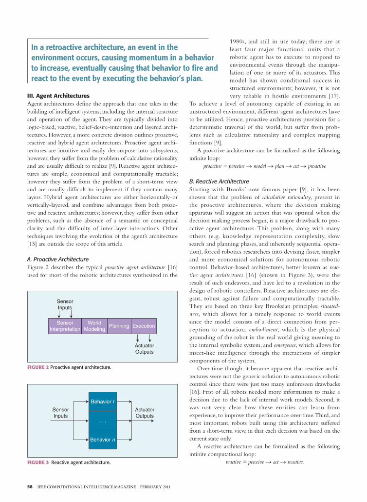
A. Proactive ArchitectureFigure 2 describes the typical proactive agent architecture [16]
used for most of the robotic architectures synthesized in the
1980s, and still in use today; there are at
least four major functional units that a
robotic agent has to execute to respond to
environmental events through the manipu-
lation of one or more of its actuators. This
model has shown conditional success in
structured environments; however, it is not
very reliable in hostile environments [17].
To achieve a level of autonomy capable of existing in an
unstructured environment, different agent architectures have
to be utilized. Hence, proactive architectures provision for a
deterministic traversal of the world, but suffer from prob-
lems such as calculative rationality and complex mapping
functions [9].
A proactive architecture can be formalized as the following
infinite loop:
proactive = perceive S model S plan S act S proactive
B. Reactive ArchitectureStarting with Brooks’ now famous paper [9], it has been
shown that the problem of calculative rationality, present in
the proactive architectures, where the decision making
apparatus will suggest an action that was optimal when the
decision making process began, is a major drawback to pro-
active agent architectures. This problem, along with many
others (e.g. knowledge representation complexity, slow
search and planning phases, and inherently sequential opera-
tion), forced robotics researchers into devising faster, simpler
and more economical solutions for autonomous robotic
control. Behavior-based architectures, better known as reac-
tive agent architectures [16] (shown in Figure 3), were the
result of such endeavors, and have led to a revolution in the
design of robotic controllers. Reactive architectures are ele-
gant, robust against failure and computationally tractable.
They are based on three key Brooksian principles: situated-
ness, which allows for a timely response to world events
since the model consists of a direct connection from per-
ception to actuation, embodiment, which is the physical
grounding of the robot in the real world giving meaning to
the internal symbolic system, and emergence, which allows for
insect-like intelligence through the interactions of simpler
components of the system.
Over time though, it became apparent that reactive archi-
tectures were not the generic solution to autonomous robotic
control since there were just too many unforeseen drawbacks
[16]. First of all, robots needed more information to make a
decision due to the lack of internal work models. Second, it
was not very clear how these entities can learn from
experience, to improve their performance over time. Third, and
most important, robots built using this architecture suffered
from a short-term view, in that each decision was based on the
current state only.
A reactive architecture can be formalized as the following
infinite computational loop:
reactive = perceive S act S reactive.
Sensor
Inputs
Sensor
Interpretation
World
ModelingPlanning Execution
Actuator
Outputs
FIGURE 2 Pro active agent architecture.
FIGURE 3 Reactive agent architecture.
Sensor
Inputs
Actuator
Outputs
Behavior l
Behavior n
. . .
In a retroactive architecture, an event in the environment occurs, causing momentum in a behavior to increase, eventually causing that behavior to fire and react to the event by executing the behavior’s plan.

FEBRUARY 2011 | IEEE COMPUTATIONAL INTELLIGENCE MAGAZINE 59
C. Hybrid ArchitectureDue to the aforementioned hindrances, researchers began
combining the two extremes into 3-layer systems (reactive
near the bottom, proactive near the top and an intermediate
layer connecting the two), that have been dubbed hybrid agent
architecture [16]. Today, they are the most popular [18] class of
robotic agent architectures due to their natural decomposition
of functionality into the individual reactive, proactive or
abstract layers. Two types of hybrid architectures exist, one
with horizontal layering and the other with vertical layering.
The former has each layer connected to the sensors and actua-
tors, with a mediator deciding which layer has control over the
body at any time, while the latter has a one or two-pass orga-
nizational scheme where information and command both flow
upwards (one-pass) or information flows upwards and com-
mands flow downwards (two-pass). Vertically layered hybrid
agent architectures suffer from a loss of flexibility and weak
fault-tolerance, whilst horizontally-layered hybrid agent archi-
tectures suffer from complex mediation modules in the case of
real-world robots.
D. Retroactive ArchitectureWe now take a look at a novel agent architecture that combines
both proactive and reactive characteristics. In a retroactive architec-
ture, an event in the environment occurs, causing momentum in
a behavior to increase, eventually causing that behavior to fire and
react to the event by executing the behavior’s plan. The events of
importance are changes in the perceived world attributes that the
mind is concerned with; i.e., ones that conflict with its world
goals. The reactive characteristic of this architecture involves pre-
cisely knowing which behavior to fire through momentum resolu-
tion, while the proactive characteristic of this architecture involves
precisely knowing how to behave through plan execution. Figure 4
depicts the retroactive agent architecture, which augments both
Actuator Outputs
Mind Outputs
Perception
Action
ExpectationWorld
Modelling
Validity
Sensor
Inputs
Mind
Inputs
FIGURE 4 Retroacti ve agent architecture.
Actuators
ActionReconfigurable
Subsumption
Architecture
Sensor Processing
Architecture
Sensor
DataSensor
Data
Filtered Config.
Parameters
World
Perception Expectation
Deliberation
Architecture
Sensor Fusion
Architecture
Assertions
Reasserti
on
Retroaction
Mind
Data
Mind
Validation
Proaction
Proassertion
Reaction
Retroassertion
Fire
d B
ehavio
rs
FIGURE 5 Retroactiv e agent architecture—synaptic acts.
60 IEEE COMPUTATIONAL INTELLIGENCE MAGAZINE | FEBRUARY 2011
reactive and proactive architectures, through its validation block
by feeding back into the mind and predicting the next event that
will occur, based on previous experiences.
The retroactive agent architecture builds
on the importance of synaptic feedback,
where, for example, every sensed event elicits
a reaction by the agent onto the world to
handle the event, a retroassertion (i.e., future
validation) onto the agent’s mind to compartmentalize the
new or old data, and subsequently a possible proaction onto
the world again to seek more information about the event.
The authors have identified six synaptic acts, namely reactions,
proactions, retroactions, reassertions, proassertions and retroas-
sertions, which if observed from the outside, ascribe intelli-
gent behavior to machines. To better visualize the synaptic
acts, the reader is pointed towards Figure 5. A retroactive
architecture allows an autonomous robot to learn over time,
solving the short-term view of reactive systems, and to
respond in real-time to world events, solving the calculative
rationality of proactive systems.
A retroactive architecture can be formalized as the follow-
ing infinite loops:
retroactive = React i Proact i Retroact
React = Perceive S Act S React
Proact = (Perceive S Expect) S Model S Act S Proact
Retroact = Expect 4 Model S Act S Retroact
Perceive = see i hear i smell i taste i feel i range i retrieveMem
Act = translate i rotate i storeMem i touch
Expect = momentum i memory i frustration i conflict
where
React process describing reactive characteristics;
Proact process describing proactive characteristics;
Retroact process describing retroactive characteristics;
Perceive process describing perceptual capabilities;
Act process describing actuation capabilities; and
Expect process describing expectation capabilities.
IV. Experimental SetupTo support a MAS-based architecture, the ISA’s hardware has
to be flexible, as well as reliable, while its software has to be
scaleable, as well as robust. After careful deliberations, it was
decided that the Altera Nios development kit [19] would be
the ideal hardware platform, as it provides flexibility of design
updates through its Stratix field-programmable gate array
(FPGA), as well as reliability through its soft-core 32-bit
reduced instruction set computer (RISC) Nios processor.
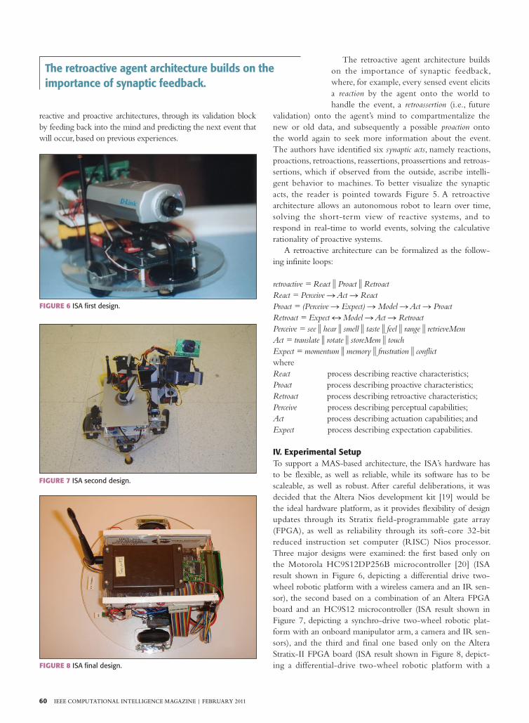
Three major designs were examined: the first based only on
the Motorola HC9S12DP256B microcontroller [20] (ISA
result shown in Figure 6, depicting a differential drive two-
wheel robotic platform with a wireless camera and an IR sen-
sor), the second based on a combination of an Altera FPGA
board and an HC9S12 microcontroller (ISA result shown in
Figure 7, depicting a synchro-drive two-wheel robotic plat-
form with an onboard manipulator arm, a camera and IR sen-
sors), and the third and final one based only on the Altera
Stratix-II FPGA board (ISA result shown in Figure 8, depict-
ing a differential-drive two-wheel robotic platform with a
FIGURE 6 ISA first design.
FIGURE 7 ISA second design.
FIGURE 8 ISA final design.
The retroactive agent architecture builds on the importance of synaptic feedback.
FEBRUARY 2011 | IEEE COMPUTATIONAL INTELLIGENCE MAGAZINE 61
digital compass, an IR sensor, a temperature
sensor and a RF modem).
The robot controller designs allowed us
more flexibility as we progressed, until we
reached the final solution, which currently
allows adding any digital interface in the
FPGA, as well as any software interface
in the soft-core microprocessor. The
latter is a 50 MHz 32-bit RISC proces-
sor that can be instantiated more than
once on the Stratix-II FPGA, easily
provisioning for a multiprocessor sys-
tem-on-chip. The robot controller also
contains 16 MB of flash memory, 1 MB
of static RAM, 16 MB of SDRAM, a
CompactFlash connector for Type I
CompactFlash cards and an on-board
Ethernet MAC/PHY device. This
board also serves as a development
platform due to its on-board Mictor connectors for
hardware and software debug and 5V-tolerant expansion/
prototype headers for simple and fast sensor and experimen-
tal device addition.
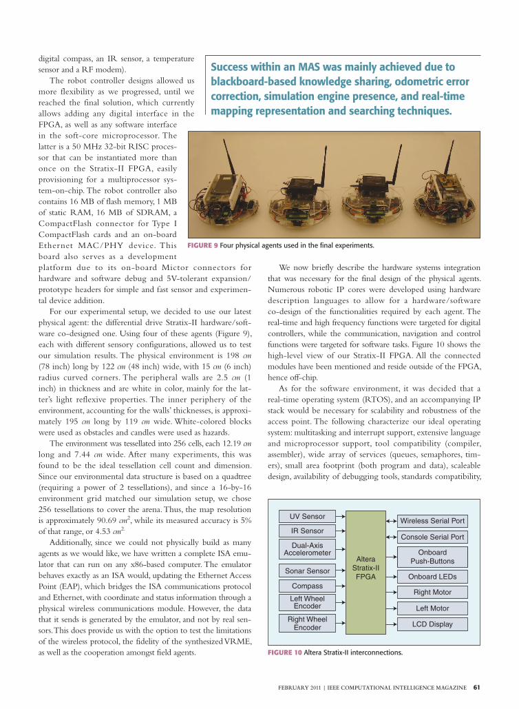
For our experimental setup, we decided to use our latest
physical agent: the differential drive Stratix-II hardware/soft-
ware co-designed one. Using four of these agents (Figure 9),
each with different sensory configurations, allowed us to test
our simulation results. The physical environment is 198 cm
(78 inch) long by 122 cm (48 inch) wide, with 15 cm (6 inch)
radius curved corners. The peripheral walls are 2.5 cm (1
inch) in thickness and are white in color, mainly for the lat-
ter’s light reflexive properties. The inner periphery of the
environment, accounting for the walls’ thicknesses, is approxi-
mately 195 cm long by 119 cm wide. White-colored blocks
were used as obstacles and candles were used as hazards.
The environment was tessellated into 256 cells, each 12.19 cm
long and 7.44 cm wide. After many experiments, this was
found to be the ideal tessellation cell count and dimension.
Since our environmental data structure is based on a quadtree
(requiring a power of 2 tessellations), and since a 16-by-16
environment grid matched our simulation setup, we chose
256 tessellations to cover the arena. Thus, the map resolution
is approximately 90.69 cm2, while its measured accuracy is 5%
of that range, or 4.53 cm2.
Additionally, since we could not physically build as many
agents as we would like, we have written a complete ISA emu-
lator that can run on any x86-based computer. The emulator
behaves exactly as an ISA would, updating the Ethernet Access
Point (EAP), which bridges the ISA communications protocol
and Ethernet, with coordinate and status information through a
physical wireless communications module. However, the data
that it sends is generated by the emulator, and not by real sen-
sors. This does provide us with the option to test the limitations
of the wireless protocol, the fidelity of the synthesized VRME,
as well as the cooperation amongst field agents.
We now briefly describe the hardware systems integration
that was necessary for the final design of the physical agents.
Numerous robotic IP cores were developed using hardware
description languages to allow for a hardware/software
co-design of the functionalities required by each agent. The
real-time and high frequency functions were targeted for digital
controllers, while the communication, navigation and control
functions were targeted for software tasks. Figure 10 shows the
high-level view of our Stratix-II FPGA. All the connected
modules have been mentioned and reside outside of the FPGA,
hence off-chip.
As for the software environment, it was decided that a
real-time operating system (RTOS), and an accompanying IP
stack would be necessary for scalability and robustness of the
access point. The following characterize our ideal operating
system: multitasking and interrupt support, extensive language
and microprocessor support, tool compatibility (compiler,
assembler), wide array of services (queues, semaphores, tim-
ers), small area footprint (both program and data), scaleable
design, availability of debugging tools, standards compatibility,
FIGURE 9 Fo ur physical agents used in the final experiments.
UV Sensor
IR Sensor
Dual-AxisAccelerometer
Sonar Sensor
Compass
Left WheelEncoder
Right WheelEncoder
Altera
Stratix-II
FPGA
Wireless Serial Port
Console Serial Port
Onboard
Push-Buttons
Onboard LEDs
Right Motor
Left Motor
LCD Display
FIGURE 10 Al tera Stratix-II interconnections.
Success within an MAS was mainly achieved due to blackboard-based knowledge sharing, odometric error correction, simulation engine presence, and real-time mapping representation and searching techniques.

62 IEEE COMPUTATIONAL INTELLIGENCE MAGAZINE | FEBRUARY 2011
extensive device driver support and industrial and academic
support. It is imperative to have a low interrupt latency to
allow for re-entrancy and to support pre-emptive scheduling
as all those characteristics help us meet real-time constraints
when dealing with the agent’s computational requirements;
hence, after much deliberation, it was found that the uC/
OS-II [21] RTOS met most of these requirements. As for the
IP stack, lightweight IP (lwIP) [22] was also selected as the
most suitable candidate.
Let us now briefly explain the agent’s SLAM software struc-
ture that is depicted in Figure 11. The world model holds the
agent’s current view of the external environment surrounding
it. It feeds the control subsumption architecture, which reactively
behaves to the world’s sensory inputs by controlling the agent’s
motors. A navigation module decides how to freely navigate in
the world, by localizing the agent (localizer module) and driv-
ing the proportional-integrator controller (PIC) in charge of keeping
the physical agent moving at a constant velocity and in a
straight forward direction. The utilized motors are servo
motors, requiring pulse-width modulation (PWM) controllers. A
separate, but analogous, communication subsumption architecture
controls the on-board modems to react to multi-sensor fusion
requests and acknowledgements, as well as to broadcast sensory
and positioning information.
The control subsumption architecture is shown in Figure 12
and contains six behaviors that, if fired, subsume the lower prior-
ity behaviors, and control the servo motors accordingly. An arbi-
tration task periodically wakes up and decides which behavior
fires, depending on the current sensor inputs. The latter task
sleeps for 10 ms; hence, providing the agent with a sampling fre-
quency of 100 Hz. The realized control behaviors are:
1) Escape behavior fires if a bump is felt by the dual-axis
accelerometer;
2) Avoid behavior fires if an object is detected to be too
close to the agent;
3) Contain behavior fires if an environmental sensor value
increases beyond a certain threshold;
4) Drive behavior fires whenever a wheel encoder or digital
compass sensor value changes, and is the main driving
behavior of the agent, allowing it to reach its goals;
5) Explore behavior fires if there are additional unexplored
regions in the environment. It consists of randomly
moving the agent within the environment; and
6) Monitor behavior is the default one, and is fired if no other
higher priority behavior fires. It allows the agent to drive
back and forth within a certain path to monitor its local
environment.
The communication subsumption architecture is shown in
Figure 13 and contains four behaviors that, if fired, subsume the
lower priority behaviors, and control the wireless modem
accordingly. The two lower priority behaviors, Request and
Acknowledge, only appear in the distributed scenarios. An arbi-
tration task periodically wakes up and decides which behavior
fires, depending on the current sensor inputs. The realized
communication behaviors are as follows:
1) Localize behavior fires if a change occurs in the agent’s pose;
2) Announce behavior fires if a change occurs in the agent’s
sensors;
3) Request behavior fires when additional mapping or status
information is required by the agent; and
4) Acknowledge behavior fires when a request has been processed
and accepted.
FIGURE 12 Cont rol subsumption architecture.
Bumper
IR/Sonar
UV/Temperature
Enc./Compass
Escape
Avoid
Contain
Drive
Explore
Monitor Motors
S
S
S
S
S
FIGURE 13 Commu nication subsumption architecture.
Encoders/Compass
Bump/IRSonar/UV
Localize
Announce
Request
Acknowledge Modem
S
S
S
WorldModel
ControlSubsumptionArchitecture
NavigationModule
LocalizerModule
Pose
Proportional IntegratorController
Optical Encoders
Magnetic Compass
PWMController
ServoMotors
Velocities
FIGURE 11 Age nt SLAM software.

FEBRUARY 2011 | IEEE COMPUTATIONAL INTELLIGENCE MAGAZINE 63
The experimental setup included a territory with a sample
scenario that the agents were securing. Lit candles were used to
indicate hazards while objects were used to indicate obstacles.
Building blocks were used to indicate perimeters to be secured.
The four physical agents proceed to map
the environment using the TIMM meth-
odology, then continuously monitor and
secure the designated perimeters, and pro-
duce a VRME output such as the one
shown in Figure 14. The obstacles were
modeled as grey vertical strips, while haz-
ards were modeled as red horizontal strips.
Figure 15 shows the path taken by
one physical agent as it traverses the envi-
ronment while mapping and monitoring
it. The path cells are modeled as green
horizontal strips (a different green hue is
used for each agent), and were placed at
each coordinate in the environment
whenever an agent sent an InteRCom
coordinate update packet to the EAP.
Finally, the ISAs form a mobile ad-
hoc network and communicate using our
devised Intelligent Robotic Communication
(InteRCom) protocol. InteRCom is a cost
effective protocol that attempts to meet
the policies set forth in [23]. Those poli-
cies are summarized below:
❏ Connection establishment and
resource allocation;
❏ Quality-of-service capable sensor traf-
fic delivery;
❏ ”Intelligent networking” on distribut-
ed architectures; and
❏ Ad-hoc networking infrastructure
support.
The protocol was designed to be sca-
leable and robust. It is scaleable because
it is extremely easy to incorporate het-
erogeneous sensor, as well as haptic
feedback, information through InteR-
Com’s packet structure. The protocol is
robust because it is built on top of the
UDP/IP stack that was aforementioned,
and it adds error checking at the appli-
cation level, to counter the no reliability
constraint of the UDP network layer
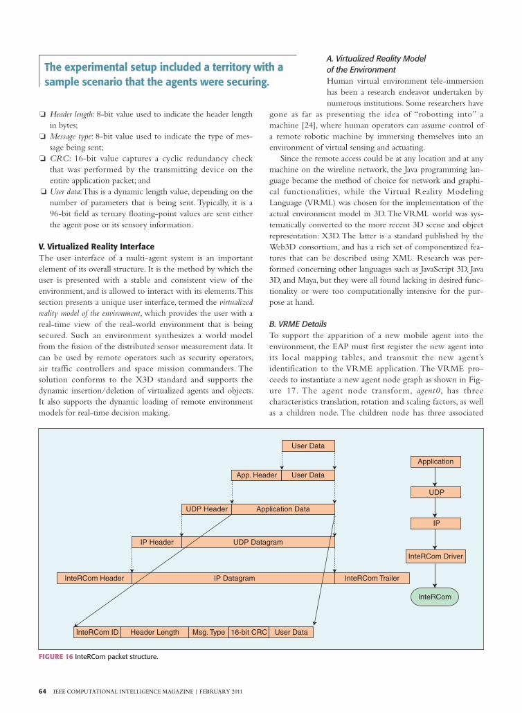
protocol. Figure 16 shows InteRCom’s
packet structure. InteRCom currently
operates over an augmented wireless
serial line IP (SLIP) protocol that allows
for multiple devices to communicate by
sharing a common wireless channel.
This is accomplished through the addi-
tions of the InteRCom header and
trailer to every IP datagram. As can be seen in the figure, the
packet is subdivided into 5 main fields:
❏ InteRCom ID: 8-bit value used to uniquely identify the
communicating device;
FIGURE 15 VRME ex perimental snapshot—an agent’s path.
FIGURE 14 VRME e xperimental snapshot—discovering a perimeter.
64 IEEE COMPUTATIONAL INTELLIGENCE MAGAZINE | FEBRUARY 2011
❏ Header length: 8-bit value used to indicate the header length
in bytes;
❏ Message type: 8-bit value used to indicate the type of mes-
sage being sent;
❏ CRC: 16-bit value captures a cyclic redundancy check
that was performed by the transmitting device on the
entire application packet; and
❏ User data: This is a dynamic length value, depending on the
number of parameters that is being sent. Typically, it is a
96-bit field as ternary floating-point values are sent either
the agent pose or its sensory information.
V. Virtualized Reality InterfaceThe user interface of a multi-agent system is an important
element of its overall structure. It is the method by which the
user is presented with a stable and consistent view of the
environment, and is allowed to interact with its elements. This
section presents a unique user interface, termed the virtualized
reality model of the environment, which provides the user with a
real-time view of the real-world environment that is being
secured. Such an environment synthesizes a world model
from the fusion of the distributed sensor measurement data. It
can be used by remote operators such as security operators,
air traffic controllers and space mission commanders. The
solution conforms to the X3D standard and supports the
dynamic insertion/deletion of virtualized agents and objects.
It also supports the dynamic loading of remote environment
models for real-time decision making.
A. Virtualized Reality Model of the EnvironmentHuman virtual environment tele-immersion
has been a research endeavor undertaken by
numerous institutions. Some researchers have
gone as far as presenting the idea of “robotting into” a
machine [24], where human operators can assume control of
a remote robotic machine by immersing themselves into an
environment of virtual sensing and actuating.
Since the remote access could be at any location and at any
machine on the wireline network, the Java programming lan-
guage became the method of choice for network and graphi-
cal functionalities, while the Virtual Reality Modeling
Language (VRML) was chosen for the implementation of the
actual environment model in 3D. The VRML world was sys-
tematically converted to the more recent 3D scene and object
representation: X3D. The latter is a standard published by the
Web3D consortium, and has a rich set of componentized fea-
tures that can be described using XML. Research was per-
formed concerning other languages such as JavaScript 3D, Java
3D, and Maya, but they were all found lacking in desired func-
tionality or were too computationally intensive for the pur-
pose at hand.
B. VRME DetailsTo support the apparition of a new mobile agent into the
environment, the EAP must first register the new agent into
its local mapping tables, and transmit the new agent’s
identification to the VRME application. The VRME pro-
ceeds to instantiate a new agent node graph as shown in Fig-
ure 17. The agent node transform, agent0, has three
characteristics translation, rotation and scaling factors, as well
as a children node. The children node has three associated
FIGURE 16 InteRCom packet structure.
User Data
User Data
Application Data
App. Header
UDP Header
IP Header
InteRCom Header
InteRCom ID Header Length Msg. Type 16-bit CRC User Data
InteRCom Trailer
InteRCom Driver
InteRCom
IP Datagram
UDP Datagram
IP
UDP
Application
The experimental setup included a territory with a sample scenario that the agents were securing.
FEBRUARY 2011 | IEEE COMPUTATIONAL INTELLIGENCE MAGAZINE 65
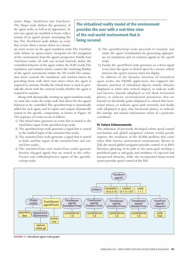
nodes: Shape, TouchSensor and TimeSensor.
The Shape node defines the geometry of
the agent node, as well as its appearance. In
our case, agents are modeled as boxes with a
texture of an agent’s picture enveloping the
box. The TouchSensor node defines an event
that occurs when a mouse down or a mouse
up event occurs on the agent transform node. The ViewPoint
node defines an agent-centric viewpoint for the navigation
of the environment from the agent’s perspective. Finally, four
TimeSensor nodes, all with one second intervals, define the
controlled behavior of the agent within the X3D world. The
translation and rotation timers control the rendering fluidity
of the agent’s movements within the 3D world. The anima-
tion timer controls the translation and rotation timers by
providing them with their start times when the agent is
required to animate. Finally, the reload timer is used to peri-
odically check with the external world, whether the agent is
required to animate.
Along with dynamically creating an agent transform node,
we must also create the script node that allows for the agent’s
behavior to be controlled. The agentMoveScript is dynamically
added for each agent, and its inputs and outputs dynamically
routed to the specific components, as shown in Figure 18.
The sequence of events occurs as follows:
1) The reload timer generates an event that is routed to the
reloadValues input of the agentMoveScript node;
2) The agentMoveScript node generates a signal that is routed
to the enabled input of the animationTimer node;
3) The animationTimer node generates a signal that is routed
to both startTime inputs of the translationTimer and rota-
tionTimer nodes;
4) The translationTimer and rotationTimer nodes generate
fraction changed signals that are routed to the setPos-
Fraction and setHeadingFraction inputs of the agentMo-
veScript node;
5) The agentMoveScript node proceeds to translate and
rotate the agent virtualization by generating appropri-
ate set translation and set rotation signals to the agent0
node;
6) Finally, the agent0Touch node generates an isActive signal
every time the agent is clicked upon by a mouse, which
retrieves the agent’s sensory status for display.
In addition to the dynamic insertion of virtualized
agent nodes, the VRME application also supports the
dynamic insertion of virtualized objects, mainly obstacles
(displayed as white thin vertical stripes), to indicate walls
and barriers, hazards (displayed as red thick horizontal
plates), to indicate environmental parameters that are
beyond set thresholds, paths (displayed as colored thin hori-
zontal plates), to indicate agent path traversals, and finally,
cells (displayed as grey thin horizontal plates), to indicate
the entropy and mutual information values of a particular
coordinate.
VI. Future EnhancementsThe utilization of previously developed robust speed control
mechanism and global navigation scheme would greatly
improve the resolution of the SLAM problem that exists
when ISAs traverse unstructured environments. Shown in
[25], the neural global navigation provides control of an ISA’s
direction, planning of its path to the main goal, tracking a
predefined path as sub-goals, and avoidance of expected and
unexpected obstacles, while the incorporated fuzzy-neural
system provides speed control of the ISA.
Transform
agent0
childern translation
10 0.3 10
rotation
0 1 0 1.57
scale
1 1 1
Shape
mISA0TouchSensor
agent0Touch
TimeSensoragent0
TranslationTimer
TimeSensoragent0
RotationTimer
TimeSensoragent0
AnimationTimer
TimeSensoragent0
ReloadTimer
ViewPointagent0
Viewpoint
geometry
BoxappearanceAppearance
active
true
texture
mISA.gif
cycleInterval1.0
cycleInterval1.0
cycleInterval1.0
cycleInterval1.0
jumptrue
FIGURE 17 Virtualiz ed agent node graph.
The virtualized reality model of the environment provides the user with a real-time view of the real-world environment that is being secured.

66 IEEE COMPUTATIONAL INTELLIGENCE MAGAZINE | FEBRUARY 2011
On another front, there are two ways that operations
research concepts can be used to enhance the MAS models
presented: sensor management and risk analysis. Sensor manage-
ment deals with the operational aspects of deploying a sensor
network in the field. In other words, it allows us to determine
among other factors the number of sensors, and their mix for
use in territorial security or defense systems using an optimi-
zation framework [26].
Risk often refers to the effect of uncertainty on a system’s
objectives; in this case, the uncertainty of the MAS being able
to effectively monitor and secure the large geographic area.
Risk of an event is traditionally defined as the multiplication
of the likelihood of an event occurring by its impact [27].
Risk analysis allows us to take into consideration the varia-
tions (both negative and positive) due to future unknown
events. Often, large numbers of scenarios with various
degrees of variability are generated in order
to examine future uncertainty [28]. This is
referred to as massive scenario generation
(MSG). Thus, one interesting area to investi-
gate would be the use of MSG in MAS sce-
nario evaluation in order to determine the
degree to which a particular sensor configuration is able to
mitigate risks for the application at hand.
While MSG would be a good method to assess the risk
associated with particular sensor configurations simulated
using a MAS, the high computational cost of repeatedly run-
ning a MAS does not allow a MAS to be used as a fitness
evaluation within a sensor management optimization frame-
work. Even for a very simplistic MAS-based MSG evaluation
of a single configuration, a large number of computations
would be used in the evaluation of optimization fitness
functions. Thus, as was done in the case of discrete event
simulation [29][30], creating simplified MAS models in
order to carry out sensor management-type analysis would
also be of interest.
We can also consider, within a MAS, the addition of vari-
ous risk-producing events such as external or environmental
Risk analysis allows us to take into consideration the variations (both negative and positive) due to future unknown events.
FIGURE 18 Virtualize d agent state diagram.
cycleTime (1s)
1
reloadValues
posChanged
set_translation
6b
6a
set_rotation
getStatusagent0
7
isActive
agent0Touch
headingchanged
coordChangedsetPosfraction
setHeadfraction
startTime
startTime
fraction_changed
fraction_changed
cycleTime (1s)
5a
5b
4
2
enabled
3
reloadTimer
agentMove
Scipt
agent0
Translation
Timer
agent0
Rotation
Timer
animationTimer
FEBRUARY 2011 | IEEE COMPUTATIONAL INTELLIGENCE MAGAZINE 67
risks (e.g. chemical spills, potholes, hostility measures), as well
as internal risks (e.g. power failure, sensor failure) which
impact on the good working order of a particular sensor con-
figuration. MAS models could thus be enhanced by the
inclusion of this random event mix which would further
contribute to adding a risk dimension to multi-agent sensor
models and systems.
Finally, we can also consider a dynamic sensor management
problem which is similar to dynamic vehicle routing [31]
where instead of passengers or parcels to pick up we have vari-
ous sensor types that need to be placed in various locations. In
dynamic sensor management, sensors are dynamically allocated
to perform urgently required tasks. The urgency of such a
dynamic deployment or re-deployment of a sensor would be
determined by the perceived risk of not having a sensor present
over some time period in a particular location or area. In addi-
tion, sensor cueing and hand-off between sensors would also be
important research areas.
VII. ConclusionsIn this article, a multi-agent system composed of agents that
each possess a limited amount of computational power and
communications bandwidth for a territorial security applica-
tion was designed, developed and experimentally verified.
A novel agent architecture has been presented. The retro-
active agent architecture describes a novel concept in the
design of intelligent machines. Originally attributed to Vernon
B. Mountcastle, who suggested that every part of the human’s
cortex is made up of the same structure, the common cortical
theory is now being viewed, by some neuroscientists, as the
elusive link to building truly intelligent machines [32].
Finally a virtualized reality model of the environment was
developed, created and validated by feeding real-world and
real-time sensory data begotten from physical agents, and
dynamically creating a world filled with virtualized agents,
paths, obstacles, hazards, perimeters and cells. The synchroni-
zation between the VRME and the various access points (e.g.,
EAP) also allows for agents to drop in and out of range, or in
and out of the environment completely, without affecting the
virtualized world. This seamless immersion aids human moni-
tors to remotely get safer and better acquainted with
unknown, and possibly hostile, environments, by deploying a
foraging society of robotic agents that synthesizes the VRME
in real-time.
VIII. AcknowledgmentsThis work was funded in part by the Natural Sciences and Engi-
neering Research Council (NSERC) of Canada, the Communi-
cations Research Centre Canada (CRC), and the
Communications and Information Technology Ontario (CITO).
References [1] USBX Advisory Services, “HSIC 2006; The state of play in homeland security: Criti-cal infrastructure—The next frontier,” 2006.
[2] Larus Technologies and GE Fanuc Intelligent Platforms, “21st Century Territorial Security: A sensor network approach,” White Paper, Nov. 2008.
[3] M. Woolridge, An Introduction to Multi-Agent Systems. Hoboken, NJ: Wiley, 2002.
[4] K. A. Tarabanis, P. K. Allen, and R. Y. Tsai, “A survey of sensor planning in computer vision,” IEEE Trans. Robot. Automat., vol. 11, no. 1, pp. 86–104, 1995.
[5] P. G. Balaji and D. Srinivasan, “Multi-agent system in urban traff ic signal control,” IEEE Comput. Intell. Mag., vol. 5, no. 4, pp. 43–51, Nov. 2010.
[6] R. Abielmona, E. M. Petriu, and T. E. Whalen, “Multi-Agent System Information Fusion for Environment Monitoring,” in Proc. IEEE Instrumentation and Measurement Tech-nology Conf. (IMTC’06), Sorrento, Italy, 2006, pp. 1774–1779.
[7] T. Kanade, P. Rander, and P. J. Narayanan, “Virtualized reality: Constructing virtual worlds from real scenes,” IEEE Multimedia, vol. 4, no. 1, pp. 34–47, 1997.
[8] A. Assal and V. Groza, “Agent-based resource management for smart robotic sensors,” in IEEE Canadian Conf. Electrical and Computer Engineering (CCECE’04), May 2004, vol. 4, pp. 2239–2242.
[9] R. Brooks, “A robust layered control system for a mobile robot,” IEEE J. Robot. Au-tomat., pp. 14–23, 1986.
[10] E. M. Petriu, R. Abielmona, and V. Z. Groza, “Agent-based control for a dynami-cally reconfigurable mobile robotic structure,” in Proc. IEEE Int. Workshop on Robotic Sensing (ROSE’04), May 2004, pp. 24–29.
[11] V. R. Lesser and L. D Erman, “Distributed interpretation: A model and an experi-ment,” IEEE Trans. Comput., vol. C29, no. 12, pp. 1144–1163, Dec. 1980.
[12] M. Pauly and K.-F. Kraiss, “Monitoring indoor environments using intelligent mo-bile sensors,” in Proc. 24th IECON Conf. IEEE Industrial Electronics Society, Feb. 1998, vol. 4, no. 4, pp. 2198–2203.
[13] D. J. Bruemmer, D. D. Dudenhoeffer, and M. L. Davis, “Modeling and simulation for exploring human-robot team interaction requirements,” in Proc. 2001 Winter Simula-tion Conf., 2001.
[14] F. Amigoni and M. Somalvico, “Multiagent systems for environment perception,” in Proc. AI Environmental Application Conf., 2003.
[15] K. A. de Jong, “Evolving intelligence agents: A 50 year quest,” IEEE Comput. Intell. Mag., vol. 3, no. 1, pp. 12–17, Feb. 2008.
[16] G. Weiss, Ed., Multiagent Systems: A Modern Approach to Distributed Artificial Intelligence. Cambridge, MA: MIT Press, 2001.
[17] J. Leng, J. Li, and L. C. Jain, “A role-based framework for multi-agent teaming,” Lect. Notes Comput. Sci., vol. 5179, pp. 642–649, 2008.
[18] M. Luck and M. d’Inverno, Understanding Agent Systems, 2nd ed. Berlin: Springer-Verlag, 2004.
[19] Altera Corp. (2010, Sept. 20). Nios Development Kit (Stratix Professional Edition) [Online]. Available: www.altera.com/products/devkits/kit-dev_platforms.jsp
[20] Technological Arts. (2010, Sept. 20). 9S12 C microcontroller family overview [On-line]. Available: www.technologicalarts.ca/catalog/index.php/cPath/50_75
[21] J. Labrosse, MicroC/OS-II, CMP Books, 2nd ed. 2002.
[22] A. Dunkels, “Minimal TCP/IP implementation with proxy support,” M.S. thesis, SICS—Swedish Institute of Computer Science, 2001.
[23] E. M. Petriu, N. D. Georganas, D. C. Petriu, D. Makrakis, and V. Z. Groza, “Sen-sor-based information appliances,” IEEE Instrum. Meas. Mag., vol. 3, no. 4, pp. 31–35, 2000.
[24] R. Brooks, Flesh and Machines: How Robots will Change Us. New York: Pantheon Books, 2002.
[25] M. Harb, R. Abielmona, and E. M, Petriu, “Speed control of a mobile robot using neural networks and fuzzy logic,” in Proc. Int. Joint Conf. Neural Networks (IJCNN’09), Atlanta, Georgia, June 2009, pp. 1115–1121.
[26] S. Sen, S. Narasimhan, and K. Deb, “Sensor network design of linear processes using genetic algorithms,” Comput. Chem. Eng., pp. 385–390, 1998.
[27] D. Hubbard, The Failure of Risk Management: Why It’s Broken and How to Fix It. Hobo-ken, NJ: Wiley, 2009.
[28] P. K. Davis, S. C. Bankes, and M. Egner, “Enhancing strategic planning with massive scenario generation: Theory and experiments,” RAND Corporation, 2007.
[29] S. Wesolkowski and A. Billyard, “The stochastic f leet estimation (SaFE) model,” in Proc. SpringSim, Ottawa, Canada, Apr. 2008.
[30] K. Willick, S. Wesolkowski, and M. Mazurek, “Multiobjective evolutionary algo-rithm with risk minimization applied to a f leet mix problem,” in Proc. IEEE CEC, Bar-celona, Spain, July 2010.
[31] D. Sáez , C. E. Cortés, and A. Núñez, “Hybrid adaptive predictive control for the multi-vehicle dynamic pick-up and delivery problem based on genetic algorithms and fuzzy cluster-ing,” Comput. Oper. Res., vol. 35, no.11, pp. 3412–3438, Nov. 2008.
[32] V. Mountcas tle, “An organizing principle for cerebral function: The unit model and the distributed system,” in The Mindful Brain, G. M. Edelman and V. B. Mountcastle, Eds. Cambridge, MA: MIT Press, 1978.


![Interfacing Toolbox for Robotic Arms with Real-Time ... · toolbox [2] includes functionalities for robotic manipulators, such as homogeneous transformations, direct and inverse kinematics,](https://img.pdfslide.net/doc/110x75/5e3d49b52ab5f82c814b433a/interfacing-toolbox-for-robotic-arms-with-real-time-toolbox-2-includes-functionalities.jpg)