Embed Size (px)
Citation preview

MICE Collaboration Meeting at Frascati, Jun 26~29, 2005
Iron Shield Mounting Design
Stephanie Yang
S Yang, 26-Jun-2005 2
Background to this design revision:
The previous support for the Iron Shield has the following concerns and the new design must be able to overcome these concerns :-
Its height to base width is so large that it is not considered stable for practical use. It sits there like a lollipop;
New design must be stable enough that the iron shield will not topple due to any unexpected sideway force before it is assembled into the tracker solenoid.
It requires constant use of overhead cranes during assembly to the tracker solenoid. There may be occasions when overhead crane is not available. The new design must be adaptive to smaller mobile lifting unit or fork lift etc.
S Yang, 26-Jun-2005 3
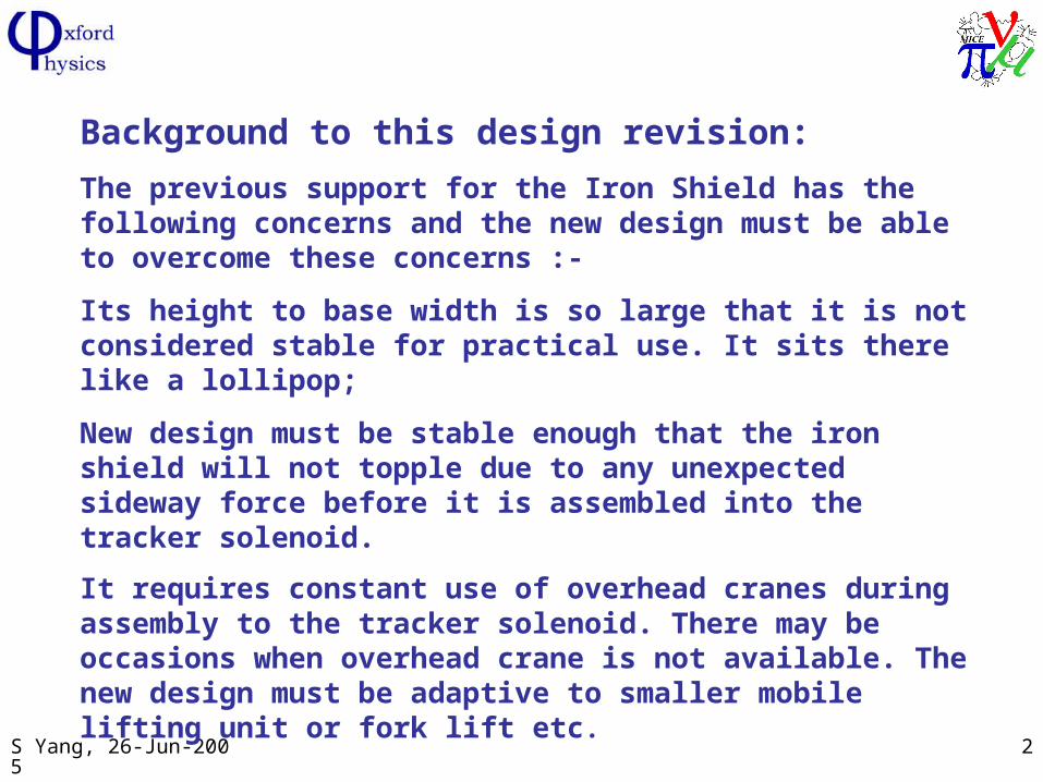
The existing design has the iron shield sitting on a frame structure before it is bolted to the Tracker solenoid cover plate via a set of spacers
S Yang, 26-Jun-2005 4
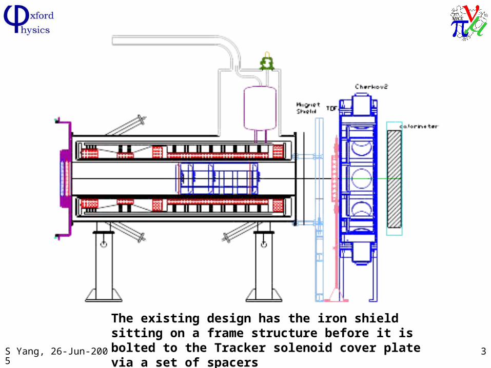
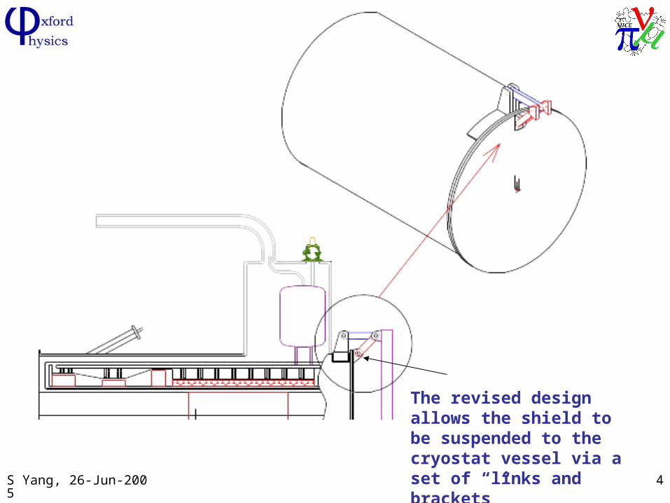
The revised design allows the shield to be suspended to the cryostat vessel via a set of “links and brackets”
S Yang, 26-Jun-2005 5
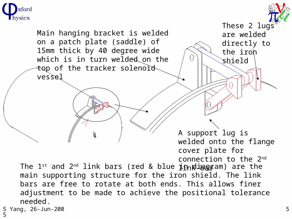
A support lug is welded onto the flange cover plate for connection to the 2nd link-bar
Main hanging bracket is welded on a patch plate (saddle) of 15mm thick by 40 degree wide which is in turn welded on the top of the tracker solenoid vessel
These 2 lugs are welded directly to the iron shield
The 1st and 2nd link bars (red & blue in diagram) are the main supporting structure for the iron shield. The link bars are free to rotate at both ends. This allows finer adjustment to be made to achieve the positional tolerance needed.
S Yang, 26-Jun-2005 6
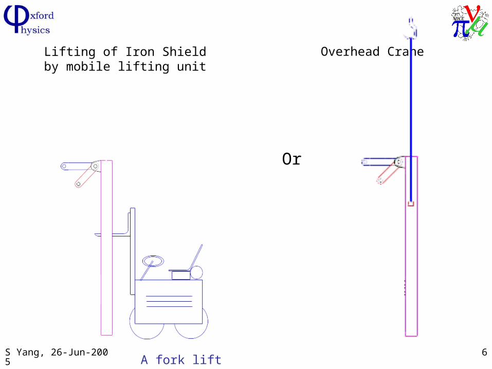
Lifting of Iron Shield by mobile lifting unit
Or
Overhead Crane
A fork lift truck, e.g.
S Yang, 26-Jun-2005 7
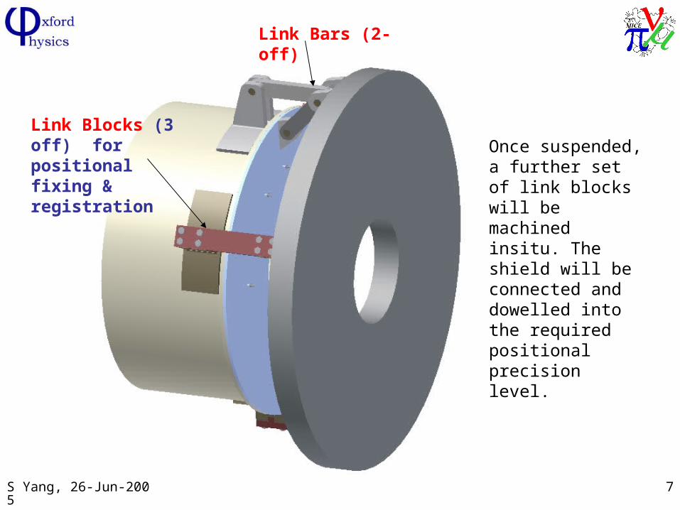
Once suspended, a further set of link blocks will be machined insitu. The shield will be connected and dowelled into the required positional precision level.
Link Blocks (3 off) for positional fixing & registration
Link Bars (2-off)
S Yang, 26-Jun-2005 8
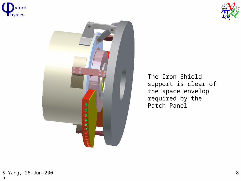
The Iron Shield support is clear of the space envelop required by the Patch Panel
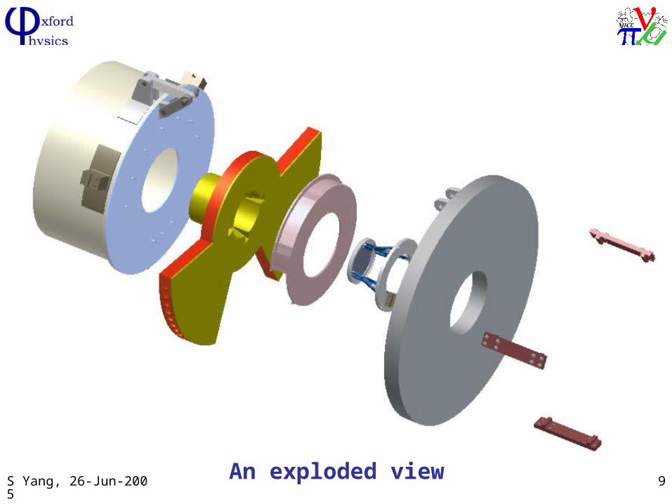
S Yang, 26-Jun-2005 9An exploded view
S Yang, 26-Jun-2005 10
How safe is the support system?
We believe it is very safe. A series of FEA calculations have been carried out to ensure that design is safe to use and allows easy assembly
S Yang, 26-Jun-2005 11
The FEA results (1)
The Truss model –At the beginning when the Shield is being hung by the two link bars, the links behave like a bar, i.e. no bending moment. In this case study, all the links are modelled with truss elements
S Yang, 26-Jun-2005 12
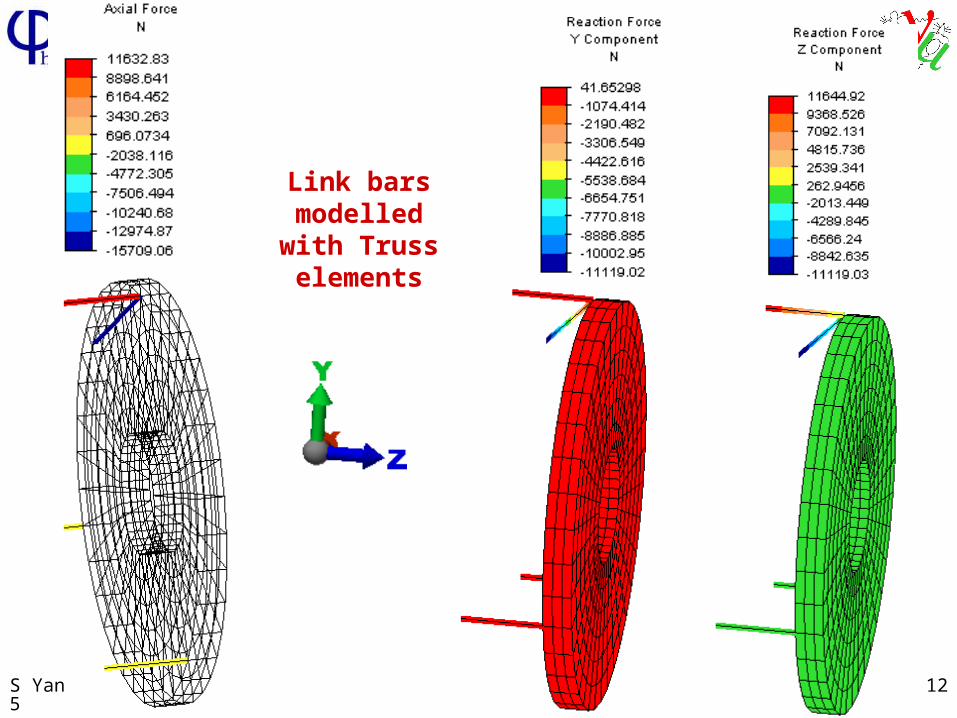
Link bars modelled with
Truss elements
S Yang, 26-Jun-2005 13
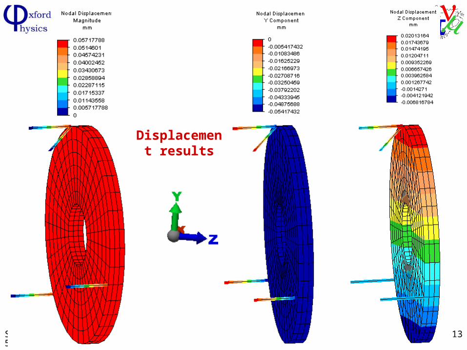
Displacement results
S Yang, 26-Jun-2005 14
The tightening of the links at the pivot points to take up and slack or positional adjustment for the shield means that these bars will behave between a truss and a beam (with bending moments and stresses). It is for this reason that the 4 links were modelled with beam elements to see if there is any build-up in stresses.
The Beam model
S Yang, 26-Jun-2005 15
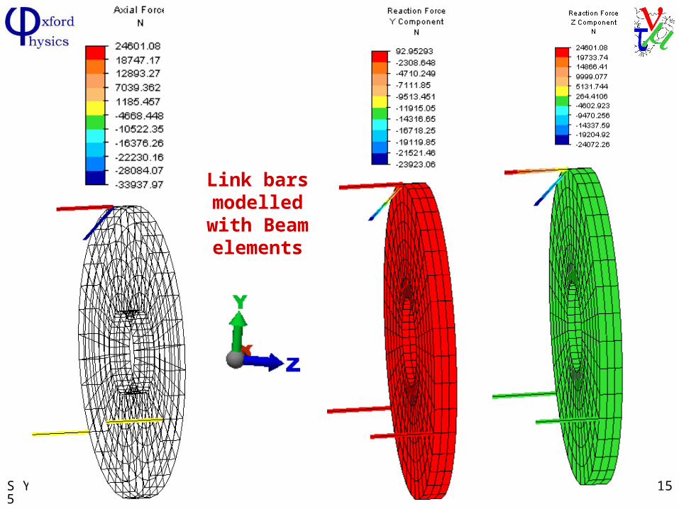
Link bars modelled
with Beam elements
S Yang, 26-Jun-2005 16
When all the link bars are modelled as truss elements, i.e. no bending stresses
Max. axial compression force in the truss members is 15710 N Max. Compressive stress is 8.72 MPa
Max axial tension force in the truss is members is 11632NMax. tensile stress is 6.24 MPa
Based on the self-weight of the magnetic shielding (~1.3 tonnes), the max. deflection (vertical drop) is 0.054mm
Results indicate that majority of the weight is supported by the top 2 link bars
When all the link bars are modelled as beam elements (allowing bending to develop):
Max. axial compression force is 33,037N causing a stress of 18.5 MPa
Max. tensile force is 24,500N causing a stress of 13.6 MPa
S Yang, 26-Jun-2005 17
FEA Result (2)
The integrity of the tracker solenoid cryostat due to a large local load
S Yang, 26-Jun-2005 18
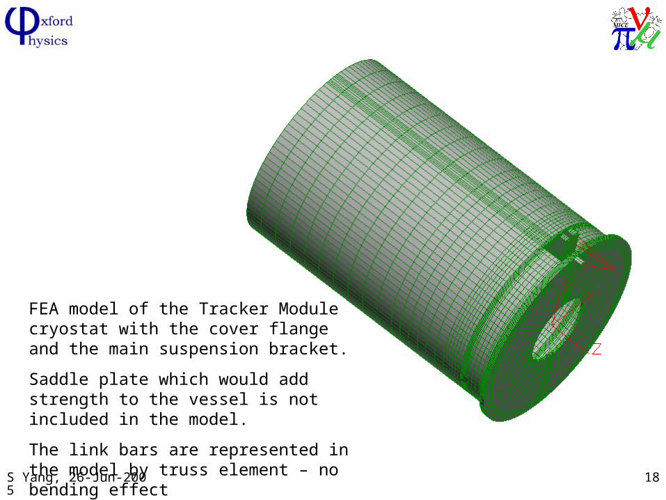
FEA model of the Tracker Module cryostat with the cover flange and the main suspension bracket.
Saddle plate which would add strength to the vessel is not included in the model.
The link bars are represented in the model by truss element – no bending effect
S Yang, 26-Jun-2005 19
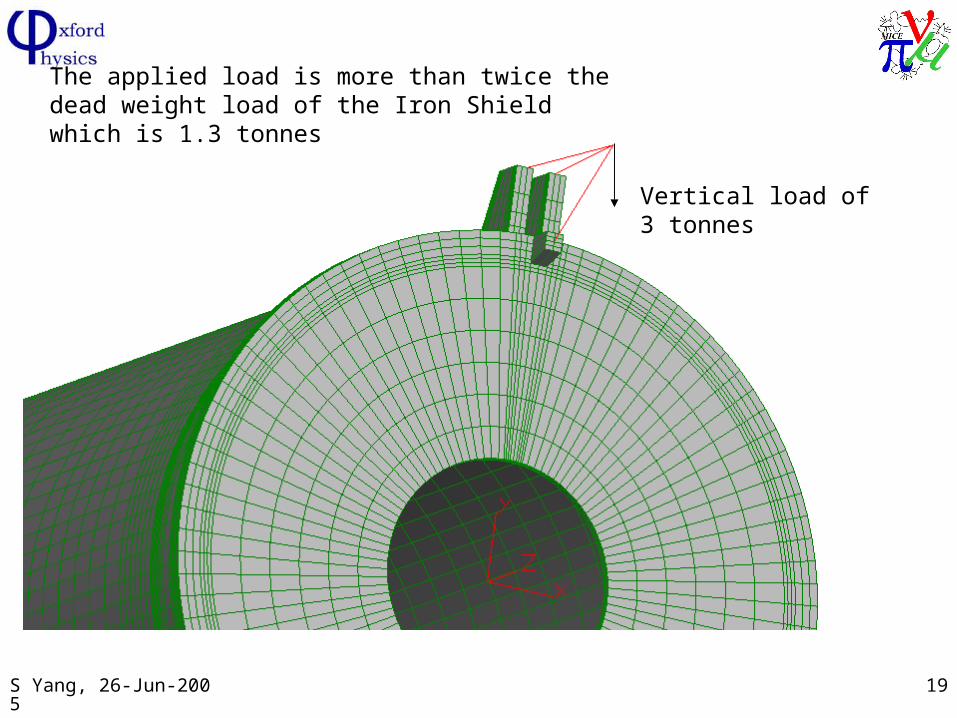
Vertical load of 3 tonnes
The applied load is more than twice the dead weight load of the Iron Shield which is 1.3 tonnes
S Yang, 26-Jun-2005 20
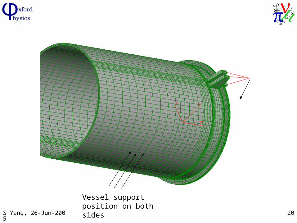
Vessel support position on both sides
S Yang, 26-Jun-2005 21
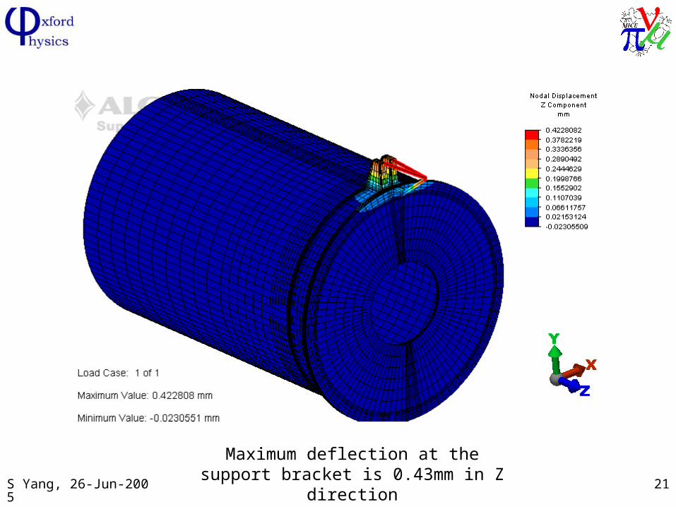
Maximum deflection at the support bracket is 0.43mm in Z direction
S Yang, 26-Jun-2005 22
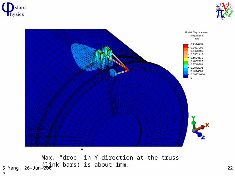
Max. “drop” in Y direction at the truss (link bars) is about 1mm.
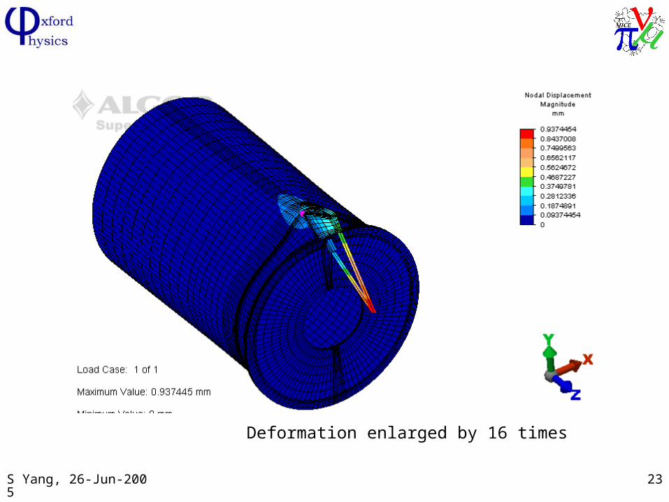
S Yang, 26-Jun-2005 23
Deformation enlarged by 16 times
S Yang, 26-Jun-2005 24
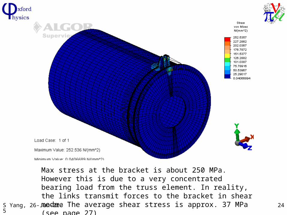
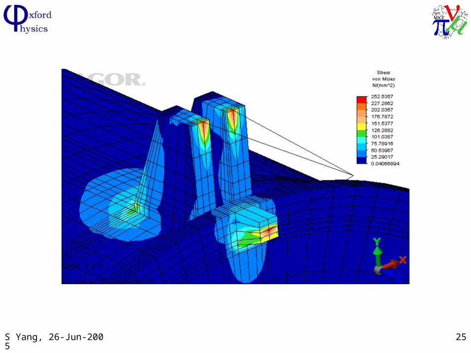
Max stress at the bracket is about 250 MPa. However this is due to a very concentrated bearing load from the truss element. In reality, the links transmit forces to the bracket in shear mode. The average shear stress is approx. 37 MPa (see page 27)
S Yang, 26-Jun-2005 25
S Yang, 26-Jun-2005 26
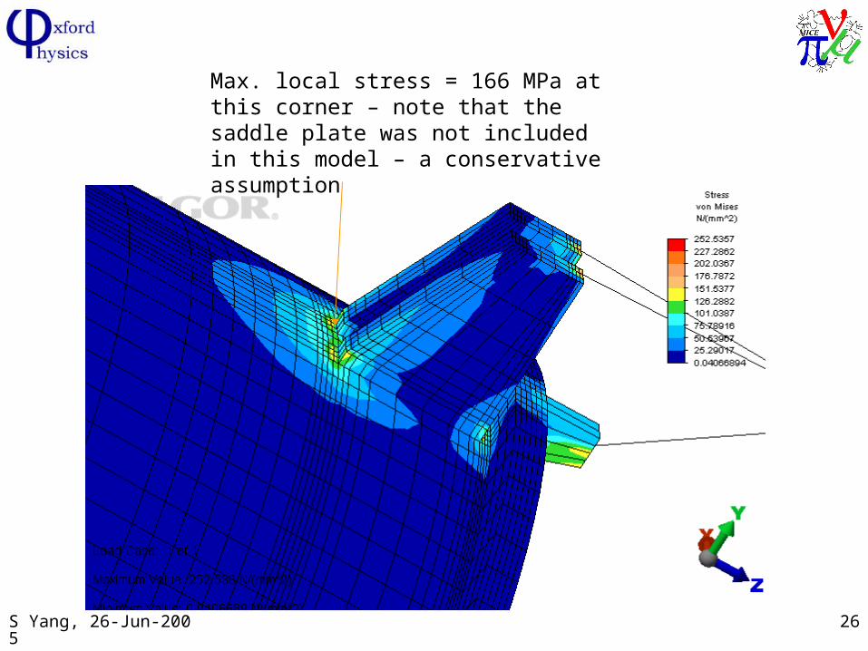
Max. local stress = 166 MPa at this corner – note that the saddle plate was not included in this model – a conservative assumption
S Yang, 26-Jun-2005 27
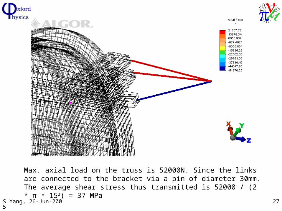
Max. axial load on the truss is 52000N. Since the links are connected to the bracket via a pin of diameter 30mm. The average shear stress thus transmitted is 52000 / (2 * π * 152) = 37 MPa

S Yang, 26-Jun-2005 28
Summary:
The latest support design allows an easy and safe assembly of the Iron Shield to the tracker module;
The purpose of the top link bars allows the Iron Shield to be suspended temporarily while the final positional adjustments are achieved by the 3 link blocks which are machined insitu for precision reason;
They are then dowelled in to provide a safe and secure attachment to the tracker module.
The FEA results show that both the link bars, the support brackets and the cryostat vessel are strong enough for the anticipated loads;