Embed Size (px)
Citation preview

| AUTOMATION
GRID
MiCOM ALSTOM P141, P142, P143, P144 & P145
Feeder Management Relay
Software Version: 36
Hardware Version: J
Update Documentation
P14x/EN AD/D84

Note: The technical manual for this device gives instructions for its installation, commissioning, and operation. However, the manual cannot cover all conceivable circumstances or include detailed information on all topics. In the event of questions or specific problems, do not take any action without proper authorization. Contact the appropriate Alstom Grid technical sales office and request the necessary information.
Any agreements, commitments, and legal relationships and any obligations on the part of Alstom Grid including settlements of warranties, result solely from the applicable purchase contract, which is not affected by the contents of the technical manual.
This device MUST NOT be modified. If any modification is made without the express permission of Alstom Grid, it will invalidate the warranty, and may render the product unsafe.
The Alstom Grid logo and any alternative version thereof are trademarks and service marks of Alstom Grid.
All trade names or trademarks mentioned herein whether registered or not, are the property of their owners.
This manual is provided for informational use only and is subject to change without notice.
© 2010, Alstom Grid. All rights reserved.

Update Documentation P14x/EN AD/D84 MiCOM P141, P142, P143, P144 & P145
UPDATE DOCUMENTATION
Date: 20th August 2007
Hardware Suffix: J
Software Version: 36
Connection Diagrams: 10P141/2/3/4/5xx (xx = 01 to 07)

P14x/EN AD/D84 Update Documentation
MiCOM P141, P142, P143, P144 & P145

Update Documentation P14x/EN AD/D84 MiCOM P141, P142, P143, P144 & P145
(AD) -1
P14x UPDATE DOCUMENTATION
In the firmware version 0360J of P14x, several changes on existing features have been added. These are described with reference to the documentation listed below:
Release Version Documentation
13.02.2007 P14x/EN M/D74 Technical Manual
Document Ref. Section Page No. Description
P14x/EN SS/H11
6.2 7
Protective class
Minor formatting change
P14x/EN TD/D74
- 2-9
Power supply
Battery Backup: description extended
Digital (“opto”) Inputs: description amended and extended
Electromagnetic compatibility (EMC)
Conducted Emissions: Class A added
Radiated Emissions: Class A added
EU directives
Product Safety: 73/23/EEC amended to 2006/95/EC
EN61010-1: 2001 amended to EN60255-27: 2005
EN60950-1: 2002 amended to EN60255-5: 2001
R&TTE Compliance: new section added
ATEX Compliance: new section added
P14x third party compliances (UL/CUL, ENA)
New section and diagrams added
Earth/sensitive fault protection
SEF cos(PHI)/: new section added
SEF sin(PHI): new section added
Under voltage protection
Accuracy: DT Pick-up and IDMT Pick-up lines amended
Over voltage protection
Accuracy: DT Pick-up and IDMT Pick-up lines amended
Date and time
New data added after Battery Alarm
P14/EN GS/D74
1.2.1 4
Front panel
Hotkeys button after figure 2 amended

P14x/EN AD/D84 Update Documentation (AD) -2
MiCOM P141, P142, P143, P144 & P145
Document Ref. Section Page No. Description
1.3.3 41
Date and time
Local Time adjustment and Daylight Saving settings added
P14x/EN ST/D74
1.3.7.4 47
Communications settings for DNP3.0 protocol
New cells added after RP1 Time Sync
P14x/EN PL/D74
1.7 25
Logic nodes
New DDB signals 592-639 descriptions added
5.2 37
DNP3.0 menu setting
New cell added after Time Sync
5.5 38
Object 20 binary counters
Description amended and additional text added
5.6 38
Object 30 analogue counters
Description amended in paragraph 1
Last sentence deleted in paragraph 2
5.7 38
Object 40 analog output
New section
5.7.1 38 Object 1 Section deleted
5.7.2 38-39
Object 20
Section deleted
5.7.3 39
Object 30
Section deleted
P14x/EN SC/D74
5.8 38
DNP3.0 configuration using MiCOM S1
Description amended in paragraph 1
New paragraph added

Update Documentation P14x/EN AD/D84 MiCOM P141, P142, P143, P144 & P145
(AD) -3
SAFETY SECTION (P14x/EN SS/H11)
6.2 Protective class
IEC 60255-27: 2005 Class I (unless otherwise specified in the equipment documentation).
EN 60255-27: 2005 This equipment requires a protective conductor (earth) connection to ensure user safety.
TECHNICAL DATA (P14x/EN TD/D74)
Power Supply
Auxiliary Voltage (Vx) Three ordering options: (i) Vx: 24 to 48 Vdc (ii) Vx: 48 to 110 Vdc, and 30 to
100Vac (rms) (iii) Vx: 110 to 250 Vdc, and 100 to
240Vac (rms) Operating Range (i) 19 to 65V (dc only for this variant) (ii) 37 to 150V (dc), 24 to 110V (ac) (iii) 87 to 300V (dc), 80 to 265V (ac) With a tolerable ac ripple of up to 12% for a dc supply, per IEC 60255-11: 1979.
Nominal Burden Quiescent burden: 11W. (Extra 1.25W when fitted with second rear Courier) Additions for energized binary inputs/outputs: Per opto input: 0.09W (24 to 54V), 0.12W (110/125V), 0.19W (220/120V). Per energized output relay: 0.13W
Power-up Time Time to power up < 11s.
Power Supply Interruption Per IEC 60255-11: 1979 The relay will withstand a 20ms interruption in the DC auxiliary supply, without de-energizing. Per IEC 61000-4-11: 1994 The relay will withstand a 20ms interruption in an AC auxiliary supply, without de-energizing.
Battery Backup Front panel mounted Type ½ AA, 3.6V (SAFT advanced battery reference LS14250) Battery life (assuming relay energized for 90% time) >10 years

P14x/EN AD/D84 Update Documentation (AD) -4
MiCOM P141, P142, P143, P144 & P145
Field Voltage Output Regulated 48Vdc Current limited at 112mA maximum output Digital (“Opto”) Inputs Universal opto inputs with programmable voltage thresholds (24/27, 30/34, 48/54, 110/125, 220/250V). May be energized from the 48V field voltage, or the external battery supply. Rated nominal voltage: 24 to 250Vdc Operating range: 19 to 265Vdc Withstand: 300Vdc, 300Vrms.
Peak current of opto input when energized is 3.5mA (0-300V) Nominal pick-up and reset thresholds: Nominal battery 24/27: 60 - 80% DO/PU (logic 0) <16.2 (logic 1) >19.2 Nominal battery 24/27: 50 - 70% DO/PU (logic 0) <12.0 (logic 1) >16.8 Nominal battery 30/34: 60 - 80% DO/PU (logic 0) <20.4 (logic 1) >24.0 Nominal battery 30/34: 50 - 70% DO/PU (logic 0) <15.0 (logic 1) >21.0 Nominal battery 48/54: 60 - 80% DO/PU (logic 0) <32.4 (logic 1) >38.4 Nominal battery 48/54: 50 - 70% DO/PU (logic 0) <24.0 (logic 1) >33.6 Nominal battery 110/125: 60 - 80% DO/PU (logic 0) <75.0 (logic 1) >88.0 Nominal battery 110/125: 50 - 70% DO/PU (logic 0) <55.0 (logic 1) >77.0 Nominal battery 220/250: 60 - 80% DO/PU (logic 0) <150.0 (logic 1) >176.0 Nominal battery 220/250: 50 - 70% DO/PU (logic 0) <110 (logic 1) >154 Recognition time: <2ms with long filter removed, <12ms with half cycle ac immunity filter on
Electromagnetic Compatibility (EMC)
1 MHz Burst High Frequency Disturbance Test Per IEC 60255-22-1: 1988, Class III, Common-mode test voltage: 2.5 kV, Differential test voltage: 1.0 kV, Test duration: 2s, Source impedance: 200Ω EIA(RS)232 ports excepted. Immunity to Electrostatic Discharge Per IEC 60255-22-2: 1996, Class 4, 15kV discharge in air to user interface, display, and exposed metalwork. Per IEC 60255-22-2: 1996, Class 3, 8kV discharge in air to all communication ports. 6kV point contact discharge to any part of the front of the product.

Update Documentation P14x/EN AD/D84 MiCOM P141, P142, P143, P144 & P145
(AD) -5
Electrical Fast Transient or Burst Requirements Per IEC 60255-22-4: 2002. Test severity Class III and IV: Amplitude: 2 kV, burst frequency 5kHz (Class III), Amplitude: 4 kV, burst frequency 2.5kHz (Class IV). Applied directly to auxiliary supply, and applied to all other inputs. EIA(RS)232 ports excepted. Surge Withstand Capability IEEE/ANSI C37.90.1:2002: 4kV fast transient and 2.5kV oscillatory applied common mode and differential mode to opto inputs (filtered), output relays, CTs, VTs, power supply, field voltage. 4kV fast transient and 2.5kV oscillatory applied common mode to communications, IRIG- B. Surge Immunity Test EIA(RS)232 ports excepted. Per IEC 61000-4-5: 2002 Level 4, Time to half-value: 1.2/50 µs, Amplitude: 4kV between all groups and case earth, Amplitude: 2kV between terminals of each group.
Immunity to Radiated Electromagnetic Energy Per IEC 60255-22-3: 2000, Class III: Test field strength, frequency band 80 to 1000 MHz: 10 V/m, Test using AM: 1 kHz / 80%, Spot tests at 80, 160, 450, 900 MHz Per IEEE/ANSI C37.90.2: 1995: 25MHz to 1000MHz, zero and 100% square wave modulated. Field strength of 35V/m.
Radiated Immunity from Digital Communications Per EN61000-4-3: 2002, Level 4: Test field strength, frequency band 800 to 960 MHz, and 1.4 to 2.0 GHz: 30 V/m, Test using AM: 1 kHz / 80%.
Radiated Immunity from Digital Radio Telephones Per ENV 50204: 1995 10 V/m, 900MHz and 1.89GHz. Immunity to Conducted Disturbances Induced by Radio Frequency Fields Per IEC 61000-4-6: 1996, Level 3, Disturbing test voltage: 10 V

P14x/EN AD/D84 Update Documentation (AD) -6
MiCOM P141, P142, P143, P144 & P145
Power Frequency Magnetic Field Immunity Per IEC 61000-4-8: 1994, Level 5, 100A/m applied continuously, 1000A/m applied for 3s. Per IEC 61000-4-9: 1993, Level 5, 1000A/m applied in all planes. Per IEC 61000-4-10: 1993, Level 5, 100A/m applied in all planes at 100kHz/1MHz with a burst duration of 2s. Conducted Emissions Per EN 55022: 1998: Class A: 0.15 - 0.5MHz, 79dBV (quasi peak) 66dBV (average) 0.5 - 30MHz, 73dBV (quasi peak) 60dBV (average). Radiated Emissions Per EN 55022: 1998: Class A: 30 - 230MHz, 40dBV/m at 10m measurement distance 230 - 1GHz, 47dBV/m at 10m measurement distance.
EU Directives
EMC Compliance Per 89/336/EEC: Compliance to the European Commission Directive on EMC is claimed via the Technical Construction File route. Product Specific Standards were used to establish conformity: EN50263: 2000 Product Safety Per 2006/95/EC: Compliance with European Commission Low Voltage Directive. Compliance is demonstrated by reference to generic safety standards: EN60255-27: 2005 EN60255-5: 2001.
93/68/EEC
R&TTE Compliance Radio and Telecommunications Terminal Equipment (R & TTE) directive 95/5/EC. Compliance demonstrated by compliance to the Low Voltage Directive, 2006/95/EC amended by 93/68/EEC, down to zero volts by reference to safety standards. Applicable to rear communications ports. ATEX Compliance ATEX Potentially Explosive Atmospheres directive 94/9/EC, for equipment. The equipment is compliant with Article 1(2) of European directive 94/9/EC. It is approved for operation outside an ATEX

Update Documentation P14x/EN AD/D84 MiCOM P141, P142, P143, P144 & P145
(AD) -7
hazardous area. It is however approved for connection to Increased Safety, “Ex e”, motors with rated ATEX protection, Equipment Category 2, to ensure their safe operation in gas Zones 1 and 2 hazardous areas.
CAUTION - Equipment with this marking is not itself suitable for operation within a potentially explosive atmosphere. Compliance demonstrated by Notified Body certificates of compliance.
II (2) G
P14x Third Party Compliances (UL/CUL, ENA)
File Number: E202519 Issue Date: 21-04-2005 (Complies with Canadian and US requirements).
Certificate Number: 101 Issue 3 Assessment Date: 10-12-2004
Earth/Sensitive Fault Protection
Earth Fault 1 DT Pick-up: Setting 5% Minimum IDMT trip level: 1.05 x Setting 5% Drop-off: 0.95 x Setting 5% IDMT shape: 5% or 40ms whichever is greater * IEEE reset: 5% or 50ms whichever is greater DT operation: 2% or 50ms whichever is greater DT reset: 5% Repeatability: 2.5% * Reference conditions TMS = 1, TD = 1 and IN> setting of 1A operating range 2-20In
Earth Fault 2 DT Pick-up: Setting 5% Minimum IDMT Trip level: 1.05 x Setting 5% Drop-off: 0.95 x Setting 5% IDMT shape:

P14x/EN AD/D84 Update Documentation (AD) -8
MiCOM P141, P142, P143, P144 & P145
5% or 40ms whichever is greater * IEEE reset: 10% or 40ms whichever is greater DT operation: 2% or 50ms whichever is greater DT reset: 2% or 50ms whichever is greater Repeatability: 5% * Reference conditions TMS = 1, TD = 1 and IN > setting of 1A, operating range 2-20In SEF DT Pick-up: Setting 5% Minimum IDMT Trip level: 1.05 x Setting 5% Drop-off: 0.95 x Setting 5% IDMT shape: 5% or 40ms whichever is greater * IEEE reset: 7.5% or 60ms whichever is greater DT operation: 2% or 50ms whichever is greater DT reset: 5% Repeatability: 5% * Reference conditions TMS = 1, TD = 1 and IN > setting of 100mA, operating range 2-0In REF Pick-up: Setting formula 5% Drop-off: 0.80 x setting formula 5% Operating time: <60ms High pick up: Setting 5% High operating time: <30ms Repeatability: <15% Wattmetric SEF Pick-up For P=0W ISEF> 5% or P> 5% Drop off: For P>0W (0.95 x ISEF>) 5% or 0.9 x P> 5% Boundary accuracy: 5% with 1o hysteresis Repeatability: 5%
SEF Cos(PHI)/ Pick-up: Setting ±5% for angles RCA±60o Drop-off: 0.90 x Setting IDMT shape: 5% or 50ms whichever is greater * IEEE reset: 7.5% or 60ms whichever is greater DT operation: 2% or 50ms whichever is greater DT reset: 5% Repeatability:2% * Reference conditions TMS = 1, TD = 1 and IN > setting of 100mA, operating range 2-0In
SEF Sin(PHI) Pick-up: Setting ±5% for angles from RCA±60o to RCA±90o Drop-off: 0.90 x Setting IDMT shape: 5% or 50ms whichever is greater * IEEE reset:

Update Documentation P14x/EN AD/D84 MiCOM P141, P142, P143, P144 & P145
(AD) -9
7.5% or 60ms whichever is greater DT operation: 2% or 50ms whichever is greater DT reset: 5% Repeatability: 2% Reference conditions TMS = 1, TD = 1 and IN > setting of 100mA, operating range 2-0In Zero Polarizing Operating pick-up: 2%o of RCA 90% Hysteresis: <3o VN > Pick-up: Setting 10% VN > Drop-off: 0.9 x Setting 10% Negative Polarizing Operating Pick-up: 2%o of RCA 90% Hysteresis: <3o VN 2 > Pick-up: Setting 10% VN 2 > Drop-off: 0.9 x Setting 10% I2 > Pick up: Setting 10% I2 > Drop-off: 0.9 x Setting 10%
Under Voltage Protection
Accuracy DT Pick-up: Setting 5% IDMT Pick-up: Setting 5% Drop-off: 1.02 x Setting 5% IDMT shape: 2% or 50ms whichever is greater DT operation: 2% or 50ms whichever is greater Reset: <75ms Repeatability: <1%
Over Voltage Protection
Accuracy DT Pick-up: Setting 5% IDMT Pick-up: Setting 5% Drop-off: 0.98 x Setting 5% IDMT shape: 2% or 50ms whichever is greater DT operation: 2% or 50ms whichever is greater Reset: <75ms Repeatability: <1%

P14x/EN AD/D84 Update Documentation (AD) -10
MiCOM P141, P142, P143, P144 & P145
Date and Time
IRIG-B Sync: Disabled/Enabled Battery Alarm: Disabled/Enabled LocalTime Enable: Disabled/Fixed/Flexible LocalTime Offset: -720 min…720min DST Enable: Disabled/Enabled DST Offset: 30min…60min DST Start: First/Second/Third/ Fourth/Last DST Start Day: Sun/Mon/Tues/Wed/ Thurs/Fri/Sat DST Start Month: Jan/Feb/Mar/Apr/May/ Jun/Jul/Aug/Sept/Oct/ Nov/Dec DST Start Mins: 0min…1425min DST End: First/Second/Third/ Fourth/Last DST End Day: Sun/Mon/Tues/Wed/ Thurs/Fri/Sat DST End Month: Jan/Feb/Mar/Apr/ May/Jun/Jul/Aug/Sept/ Oct/Nov/Dec DST End Mins: 0min…1425min RP1 Time Zone: UTC/Local RP2 Time Zone: UTC/Local Tunnel Time Zone: UTC/Local
GETTING STARTED (P14x/EN GS/D74)
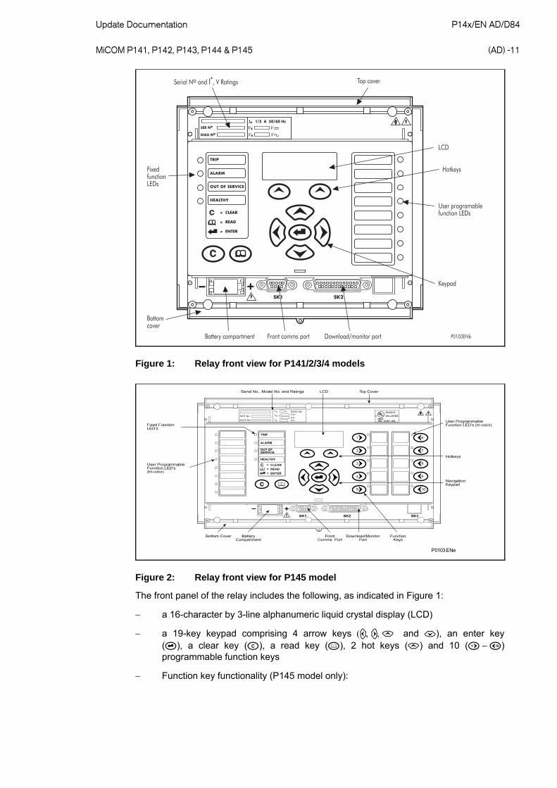
1.2.1 Front panel
The front panel of the relay is shown in Figure 1, with the hinged covers at the top and bottom of the relay shown open. Extra physical protection for the front panel can be provided by an optional transparent front cover. With the cover in place read only access to the user interface is possible. Removal of the cover does not compromise the environmental withstand capability of the product, but allows access to the relay settings. When full access to the relay keypad is required, for editing the settings, the transparent cover can be unclipped and removed when the top and bottom covers are open. If the lower cover is secured with a wire seal, this will need to be removed. Using the side flanges of the transparent cover, pull the bottom edge away from the relay front panel until it is clear of the seal tab. The cover can then be moved vertically down to release the two fixing lugs from their recesses in the front panel.
Update Documentation P14x/EN AD/D84 MiCOM P141, P142, P143, P144 & P145
(AD) -11
!"
#
#$ ! % &
'$
(
)*$
Figure 1: Relay front view for P141/2/3/4 models
P0103ENe
Figure 2: Relay front view for P145 model
The front panel of the relay includes the following, as indicated in Figure 1:
a 16-character by 3-line alphanumeric liquid crystal display (LCD)
a 19-key keypad comprising 4 arrow keys and ), an enter key (), a clear key (), a read key (), 2 hot keys () and 10 () programmable function keys
Function key functionality (P145 model only):

P14x/EN AD/D84 Update Documentation (AD) -12
MiCOM P141, P142, P143, P144 & P145
The relay front panel features control pushbutton switches with
programmable LEDs that facilitate local control. Factory default settings associate specific relay functions with these 10 direct-action pushbuttons and LEDs e.g. Enable/Disable the auto-recloser function. Using programmable scheme logic, the user can readily change the default direct-action pushbutton functions and LED indications to fit specific control and operational needs.
Hotkey functionality:
SCROLL
Starts scrolling through the various default displays.
STOP
Stops scrolling the default display.
For control of setting groups, control inputs and circuit breaker operation
P141/2/3/4 models: 12 LEDs; 4 fixed function LEDs on the left hand side of the front panel and 8 programmable function LEDs on the right hand side
P145 model: 22 LEDs; 4 fixed function LEDs, 8 tri-color programmable function LEDs on the left hand side of the front panel and 10 tri-color programmable function LEDs on the right hand side associated with the function keys
Under the top hinged cover:
The relay serial number, and the relay’s current and voltage rating information
Under the bottom hinged cover:
Battery compartment to hold the 1/2 AA size battery which is used for memory back-up for the real time clock, event, fault and disturbance records
A 9-pin female D-type front port for communication with a PC locally to the relay (up to 15m distance) via an EIA(RS)232 serial data connection
A 25-pin female D-type port providing internal signal monitoring and high speed local downloading of software and language text via a parallel data connection
SETTINGS (P14x/EN ST/D74)
1.3.3 Date and Time
Displays the date and time as well as the battery condition.
Setting Range Menu Text Default Setting
Min. Max. Step Size
Date/Time Data
Displays the relay’s current date and time.
IRIG-B Sync. Disabled Disabled or Enabled
Enable IRIG-B time synchronization.
IRIG-B Status Data Card not fitted/Card failed/Signal healthy/ No signal
Displays the status of IRIG-B.

Update Documentation P14x/EN AD/D84 MiCOM P141, P142, P143, P144 & P145
(AD) -13
Setting Range Menu Text Default Setting
Min. Max. Step Size
Battery Status Data
Displays whether the battery is healthy or not.
Battery Alarm Enabled Disabled or Enabled
Setting that determines whether an unhealthy relay battery condition is alarmed or not.
SNTP Status Data Disabled, Trying server 1, Trying server 2, Server 1 OK, Server 2 OK, No response, No valid clock
Displays information about the SNTP time synchronization status.
LocalTime Enable Disabled Disabled/Fixed/Flexible
Setting to turn on/off local time adjustments.
Disabled - No local time zone will be maintained. Time synchronization from any interface will be used to directly set the master clock and all displayed (or read) times on all interfaces will be based on the master clock with no adjustment.
Fixed - A local time zone adjustment can be defined using the LocalTime offset setting and all interfaces will use local time except SNTP time synchronization and IEC61850 timestamps.
Flexible - A local time zone adjustment can be defined using the LocalTime offset setting and each interface can be assigned to the UTC zone or local time zone with the exception of the local interfaces which will always be in the local time zone and IEC61850/SNTP which will always be in the UTC zone.
LocalTime Offset 0 -720 720 15
Setting to specify an offset of -12 to +12 hrs in 15 minute intervals for local time zone. This adjustment is applied to the time based on the master clock which is UTC/GMT
DST Enable Disabled Disabled or Enabled
Setting to turn on/off daylight saving time adjustment to local time.
DST Offset 60mins 30 60 30min
Setting to specify daylight saving offset which will be used for the time adjustment to local time.
DST Start Last First, Second, Third, Fourth, Last
Setting to specify the week of the month in which daylight saving time adjustment starts
DST Start Day Sunday Monday, Tuesday, Wednesday, Thursday,
Friday, Saturday
Setting to specify the day of the week in which daylight saving time adjustment starts
DST Start Month March January, February, March, April, May,
June, July, August, September, October, November, December
Setting to specify the month in which daylight saving time adjustment starts
DST Start Mins 60min 0 1425 15min
Setting to specify the time of day in which daylight saving time adjustment starts. This is set relative to 00:00 hrs on the selected day when time adjustment is to start.
DST End Last First, Second, Third, Fourth, Last
Setting to specify the week of the month in which daylight saving time adjustment ends.
DST End Day Sunday Monday, Tuesday, Wednesday, Thursday,
Friday, Saturday
Setting to specify the day of the week in which daylight saving time adjustment ends

P14x/EN AD/D84 Update Documentation (AD) -14
MiCOM P141, P142, P143, P144 & P145
Setting Range Menu Text Default Setting
Min. Max. Step Size
DST End Month October January, February, March, April, May,
June, July, August, September, October, November, December
Setting to specify the month in which daylight saving time adjustment ends
DST End Mins 60 0 1425 15min
Setting to specify the time of day in which daylight saving time adjustment ends. This is set relative to 00:00 hrs on the selected day when time adjustment is to end.
RP1 Time Zone Local UTC or Local
Setting for the rear port 1 interface to specify if time synchronization received will be local or universal time co-ordinated
RP2 Time Zone Local UTC or Local
Setting for the rear port 2 interface to specify if time synchronization received will be local or universal time co-ordinated
Tunnel Time Zone Local UTC or Local
Setting to specify if time synchronization received will be local or universal time co-ordinate when ‘tunneling’ courier protocol over ethernet.
1.3.7.4 Communications settings for DNP3.0 protocol
Setting Range Menu Text Default Setting
Min. Max. Step Size
COMMUNICATIONS
RP1 Protocol DNP 3.0
Indicates the communications protocol that will be used on the rear communications port.
RP1 Address 3 0 65519 1
This cell sets the unique address for the relay such that only one relay is accessed by master station software.
RP1 Baud Rate 19200 bits/s 1200 bits/s, 2400 bits/s, 4800 bits/s, 9600 bits/s, 19200 bits/s or 38400 bits/s
This cell controls the communication speed between relay and master station. It is important that both relay and master station are set at the same speed setting.
RP1 Parity None Odd, Even or None
This cell controls the parity format used in the data frames. It is important that both relay and master station are set with the same parity setting.
RP1 Physical Link Copper Copper or Fiber Optic
This cell defines whether an electrical EIA(RS) 485 or fiber optic connection is being used for communication between the master station and relay. If ‘Fiber Optic’ is selected, the optional fiber optic communications board will be required.
RP1 Time Sync. Disabled Disabled or Enabled
If set to ‘Enabled’ the DNP3.0 master station can be used to synchronize the time on the relay. If set to ‘Disabled’ either the internal free running clock, or IRIG-B input are used.

Update Documentation P14x/EN AD/D84 MiCOM P141, P142, P143, P144 & P145
(AD) -15
Setting Range Menu Text Default Setting
Min. Max. Step Size
Meas Scaling Primary Primary, Secondary or Normalized
Setting to report analog values in terms of primary, secondary or normalized(with respect to the CT/VT ratio setting) values
PROGRAMMABLE LOGIC (P14x/EN PL/D74)
1.7 Description of logic nodes
DDB No. English Text Source Description
0 Output Label 1 (Setting) Output Conditioner Output signal from output relay 1 when activated
31 Output Label 32 (Setting) Output Conditioner Output signal from output relay 32 when activated
32 Opto Label 1 (Setting) Opto Input From opto input 1 - when opto energized
63 Opto Label 32 (Setting) Opto Input From opto input 32 - when opto energized
64 - 71 Unused
72 Relay Cond. 1 PSL Input to relay output conditioner
73 Relay Cond. 2 PSL Input to relay output conditioner
74 Any Trip PSL Input to Relay Output Conditioner
75 Relay Cond. 4 PSL Input to relay output conditioner
103 Relay Cond. 4 PSL Input to relay output conditioner
104 - 111 Unused
112 Timer in 1 PSL Input to auxiliary timer 1
127 Timer in 16 PSL Input to auxiliary timer 16
128 Timer out 1 Auxiliary Timer Output from auxiliary timer 1
129 - 242 Timer out 2 …15 Auxiliary Timer Output from auxiliary timer 2 …15
143 Timer out 16 Auxiliary Timer Output from auxiliary timer 16
144 Fault REC TRIG PSL Input Trigger for Fault Recorder
145 SG-opto Invalid Group Selection Setting group selection opto inputs have detected an invalid (disabled) settings group
146 Prot'n. Disabled Commissioning Test Protection disabled - typically out of service due to test mode
147 F out of Range Frequency Tracking Frequency out of range alarm
148 VT Fail Alarm VT Supervision VTS indication alarm- failed VT (fuse blow) detected by VT supervision
149 CT Fail Alarm CT Supervision CTS indication alarm (CT supervision alarm)
150 CB Fail Alarm CB Fail Circuit breaker fail alarm
151 I^ Maint. Alarm CB Monitoring Broken current maintenance alarm - circuit breaker cumulative duty alarm set-point
152 I^ Lockout Alarm CB Monitoring Broken current lockout alarm - circuit breaker cumulative duty has been exceeded

P14x/EN AD/D84 Update Documentation (AD) -16
MiCOM P141, P142, P143, P144 & P145
DDB No. English Text Source Description
153 CB Ops Maint. CB Monitoring No of circuit breaker operations maintenance alarm - indicated due to circuit breaker trip operations threshold
154 CB Ops Lockout CB Monitoring No of circuit breaker operations maintenance lockout - excessive number of circuit breaker trip operations, safety lockout
155 CB Op Time Maint. CB Monitoring Excessive circuit breaker operating time maintenance alarm - excessive operation time alarm for the circuit breaker (slow interruption time)
156 CB Op Time Lock CB Monitoring Excessive circuit breaker operating time lockout alarm - excessive operation time alarm for the circuit breaker (too slow interruption)
157 Fault Freq. Lock CB Monitoring Excessive fault frequency lockout alarm
158 CB Status Alarm CB Status Indication of problems by circuit breaker state monitoring - example defective auxiliary contacts
159 Man CB Trip Fail CB Control Circuit breaker failed to trip (after a manual/operator trip command)
160 Man CB Cls. Fail CB Control Circuit breaker failed to close (after a manual/operator or auto-reclose close command)
161 Man CB Unhealthy CB Control
Manual circuit breaker unhealthy output signal indicating that the circuit breaker has not closed successfully after a manual close command. (A successful close also requires the circuit breaker healthy signal to reappear within the "healthy window" timeout)
162 Man No Check Sync. CB Control Indicates that the check synchronism signal has failed to appear for a manual close
163 AR Lockout Auto-Reclose Indicates an auto-reclose lockout condition - no further auto-reclosures possible until resetting
164 AR CB Unhealthy Auto-Reclose
Auto-reclose circuit breaker unhealthy signal, output from auto-reclose logic. Indicates during auto-reclose in progress, if the circuit breaker has not become healthy within the circuit breaker healthy time window
165 AR No Sys. Checks Auto-Reclose Indicates during auto-reclose in progress, if system checks have not been satisfied within the check synchronizing time window
166 System Split Check Sync. System split alarm - will be raised if the system is split (remains permanently out of synchronism) for the duration of the system split timer
167 SR User Alarm 1 PSL Triggers user alarm 1 message to be alarmed on LCD display (self-resetting)
199 SR User Alarm 32 PSL Triggers user alarm 32 message to be alarmed on LCD display (self-resetting)
200 MR User Alarm 34 PSL Triggers user alarm 34 message to be alarmed on LCD display (manual-resetting)
202 MR User Alarm 36 PSL Triggers user alarm 36 message to be alarmed on LCD display (manual-resetting))
203 I>1 Timer Block PSL Block phase overcurrent stage 1 time delay
204 I>2 Timer Block PSL Block phase overcurrent stage 2 time delay
205 I>3 Timer Block PSL Block phase overcurrent stage 3 time delay
206 I>4 Timer Block PSL Block phase overcurrent stage 4 time delay
207 Unused
208 IN1>1 Timer Blk. PSL Block earth fault measured stage 1 time delay
209 IN1>2 Timer Blk. PSL Block earth fault measured stage 2 time delay
210 IN1>3 Timer Blk. PSL Block earth fault measured stage 3 time delay
211 IN1>4 Timer Blk. PSL Block earth fault measured stage 4 time delay

Update Documentation P14x/EN AD/D84 MiCOM P141, P142, P143, P144 & P145
(AD) -17
DDB No. English Text Source Description
212 IN2>1 Timer Blk. PSL Block earth fault derived stage 1 time delay
213 IN2>2 Timer Blk. PSL Block earth fault derived stage 2 time delay
214 IN2>3 Timer Blk. PSL Block earth fault derived stage 3 time delay
215 IN2>4 Timer Blk. PSL Block earth fault derived stage 4 time delay
216 ISEF>1 Timer Blk. PSL Block sensitive earth fault stage 1 time delay
217 ISEF>2 Timer Blk. PSL Block sensitive earth fault stage 2 time delay
218 ISEF>3 Timer Blk. PSL Block sensitive earth fault stage 3 time delay
219 ISEF>4 Timer Blk. PSL Block sensitive earth fault stage 4 time delay
220 VN>1 Timer Blk. PSL Block residual overvoltage stage 1 time delay
221 VN>2 Timer Blk. PSL Block residual overvoltage stage 2 time delay
222 V<1 Timer Block PSL Block phase undervoltage stage 1 time delay
223 V<2 Timer Block PSL Block phase undervoltage stage 2 time delay
224 V>1 Timer Block PSL Block phase overvoltage stage 1 time delay
225 V>2 Timer Block PSL Block phase overvoltage stage 2 time delay
226 CLP Initiate PSL Initiate cold load pick-up
227 Ext. Trip 3ph PSL External trip 3 phase - allows external protection to initiate breaker fail, circuit breaker condition monitoring statistics, and internal auto-reclose (if enabled)
228 CB Aux. 3ph(52-A) PSL 52-A (CB closed) CB auxiliary input (3 phase)
229 CB Aux. 3ph(52-B) PSL 52-B (CB open) CB auxiliary input (3 phase)
230 CB Healthy PSL Circuit breaker healthy (input to auto-recloser - that the CB has enough energy to allow re-closing)
231 MCB/VTS PSL VT supervision input - signal from external miniature circuit breaker showing MCB tripped
232 Init. Trip CB PSL Initiate tripping of circuit breaker from a manual command
233 Init. Close CB PSL Initiate closing of circuit breaker from a manual command
234 Reset Close Dly. PSL Reset manual circuit breaker close time delay
235 Reset Relays/LED PSL Reset latched relays & LEDs (manual reset of any lockout trip contacts, auto-reclose lockout, and LEDs)
236 Reset Thermal PSL Reset thermal state to 0%
237 Reset Lockout PSL Manual control to reset auto-recloser from lockout
238 Reset CB Data PSL Reset circuit breaker maintenance values
239 Block A/R PSL Block the auto-reclose function from an external input
240 Live Line Mode PSL
Auto-reclose live line mode operation-switches the auto-reclose out of service and protection functions are not blocked. If DDB is active, the scheme is forced to live line mode, irrespective of the
auto-reclose mode select setting and auto mode and telecontrol input DDBs
241 Auto Mode PSL Auto-recloser auto mode operation-switches the auto-reclose in service

P14x/EN AD/D84 Update Documentation (AD) -18
MiCOM P141, P142, P143, P144 & P145
DDB No. English Text Source Description
242 Telecontrol Mode PSL Telecontrol mode operation selection-whereby the auto and non-auto modes of auto-reclose can be selected remotely
243 I>1 Trip Phase Overcurrent 1st stage overcurrent trip 3ph
244 I>1 Trip A Phase Overcurrent 1st stage overcurrent trip A
245 I>1 Trip B Phase Overcurrent 1st stage overcurrent trip B
246 I>1 Trip C Phase Overcurrent 1st stage overcurrent trip C
247 I>2 Trip Phase Overcurrent 2nd stage overcurrent trip 3ph
248 I>2 Trip A Phase Overcurrent 2nd stage overcurrent trip A
249 I>2 Trip B Phase Overcurrent 2nd stage overcurrent trip B
250 I>2 Trip C Phase Overcurrent 2nd stage overcurrent trip C
251 I>3 Trip Phase Overcurrent 3rd stage overcurrent trip 3ph
252 I>3 Trip A Phase Overcurrent 3rd stage overcurrent trip A
253 I>3 Trip B Phase Overcurrent 3rd stage overcurrent trip B
254 I>3 Trip C Phase Overcurrent 3rd stage overcurrent trip C
255 I>4 Trip Phase Overcurrent 4th stage overcurrent trip 3ph
256 I>4 Trip A Phase Overcurrent 4th stage overcurrent trip A
257 I>4 Trip B Phase Overcurrent 4th stage overcurrent trip B
258 I>4 Trip C Phase Overcurrent 4th stage overcurrent trip C
259 Unused
260 Broken Line Trip Broken Conductor Broken conductor trip
261 IN1>1 Trip Earth Fault 1 1st stage measured earth fault trip
262 IN1>2 Trip Earth Fault 1 2nd stage measured earth fault trip
263 IN1>3 Trip Earth Fault 1 3rd stage measured earth fault trip
264 IN1>4 Trip Earth Fault 1 4th stage measured earth fault trip
265 IN2>1 Trip Earth Fault 2 1st stage derived earth fault trip
266 IN2>2 Trip Earth Fault 2 2nd stage derived earth fault trip
267 IN2>3 Trip Earth Fault 2 3rd stage derived earth fault trip
268 IN2>4 Trip Earth Fault 2 4th stage derived earth fault trip
269 ISEF>1 Trip Sensitive Earth Fault 1st stage sensitive earth fault trip
270 ISEF>2 Trip Sensitive Earth Fault 2nd stage sensitive earth fault trip
271 ISEF>3 Trip Sensitive Earth Fault 3rd stage sensitive earth fault trip
272 ISEF>4 Trip Sensitive Earth Fault 4th stage sensitive earth fault trip
273 IREF> Trip Restricted Earth Fault Restricted earth fault trip
274 VN>1 Trip Residual Overvoltage 1st stage residual overvoltage trip
275 VN>2 Trip Residual Overvoltage 2nd stage residual overvoltage trip
276 Thermal Trip Thermal Overload Thermal overload trip

Update Documentation P14x/EN AD/D84 MiCOM P141, P142, P143, P144 & P145
(AD) -19
DDB No. English Text Source Description
277 V2> Trip Neg. Sequence O/V Negative sequence overvoltage trip
278 V<1 Trip Undervoltage 1st stage phase undervoltage trip 3ph
279 V<1 Trip A/AB Undervoltage 1st stage phase undervoltage trip A/AB
280 V<1 Trip B/BC Undervoltage 1st stage phase undervoltage trip B/BC
281 V<1 Trip C/CA Undervoltage 1st stage phase undervoltage trip C/CA
282 V<2 Trip Undervoltage 2nd stage phase undervoltage trip 3ph
283 V<2 Trip A/AB Undervoltage 2nd stage phase undervoltage trip A/AB
284 V<2 Trip B/BC Undervoltage 2nd stage phase undervoltage trip B/BC
285 V<2 Trip C/CA Undervoltage 2nd stage phase undervoltage trip C/CA
286 V>1 Trip Overvoltage 1st stage phase overvoltage trip 3ph
287 V>1 Trip A/AB Overvoltage 1st stage phase overvoltage trip A/AB
288 V>1 Trip B/BC Overvoltage 1st stage phase overvoltage trip B/BC
289 V>1 Trip C/CA Overvoltage 1st stage phase overvoltage trip C/CA
290 V>2 Trip Overvoltage 2nd stage phase overvoltage trip 3ph
291 V>2 Trip A/AB Overvoltage 2nd stage phase overvoltage trip A/AB
292 V>2 Trip B/BC Overvoltage 2nd stage phase overvoltage trip B/BC
293 V>2 Trip C/CA Overvoltage 2nd stage phase overvoltage trip C/CA
294 Any Start All Protection Any start
295 I>1 Start Phase Overcurrent 1st stage overcurrent start 3ph
296 I>1 Start A Phase Overcurrent 1st stage overcurrent start A
297 I>1 Start B Phase Overcurrent 1st stage overcurrent start B
298 I>1 Start C Phase Overcurrent 1st stage overcurrent start C
299 I>2 Start Phase Overcurrent 2nd stage overcurrent start 3ph
300 I>2 Start A Phase Overcurrent 2nd stage overcurrent start A
301 I>2 Start B Phase Overcurrent 2nd stage overcurrent start B
302 I>2 Start C Phase Overcurrent 2nd stage overcurrent start C
303 I>3 Start Phase Overcurrent 3rd stage overcurrent start 3ph
304 I>3 Start A Phase Overcurrent 3rd stage overcurrent start A
305 I>3 Start B Phase Overcurrent 3rd stage overcurrent start B
306 I>3 Start C Phase Overcurrent 3rd stage overcurrent start C
307 I>4 Start Phase Overcurrent 4th stage overcurrent start 3ph
308 I>4 Start A Phase Overcurrent 4th stage overcurrent start A
309 I>4 Start B Phase Overcurrent 4th stage overcurrent start B
310 I>4 Start C Phase Overcurrent 4th stage overcurrent start C
311 VCO Start AB Voltage Controlled O/C Voltage controlled overcurrent start AB

P14x/EN AD/D84 Update Documentation (AD) -20
MiCOM P141, P142, P143, P144 & P145
DDB No. English Text Source Description
312 VCO Start BC Voltage Controlled O/C Voltage controlled overcurrent start BC
313 VCO Start CA Voltage Controlled O/C Voltage controlled overcurrent start CA
314 Unused
315 IN1>1 Start Earth Fault 1 1st stage measured earth fault start
316 IN1>2 Start Earth Fault 1 2nd stage measured earth fault start
317 IN1>3 Start Earth Fault 1 3rd stage measured earth fault start
318 IN1>4 Start Earth Fault 1 4th stage measured earth fault start
319 IN2>1 Start Earth Fault 2 1st stage derived earth fault start
320 IN2>2 Start Earth Fault 2 2nd stage derived earth fault start
321 IN2>3 Start Earth Fault 2 3rd stage derived earth fault start
322 IN2>4 Start Earth Fault 2 4th stage derived earth fault start
323 ISEF>1 Start Sensitive Earth Fault 1st stage sensitive earth fault start
324 ISEF>2 Start Sensitive Earth Fault 2nd stage sensitive earth fault start
325 ISEF>3 Start Sensitive Earth Fault 3rd stage sensitive earth fault start
326 ISEF>4 Start Sensitive Earth Fault 4th stage sensitive earth fault start
327 VN>1 Start Residual Overvoltage 1st stage residual overvoltage start
328 VN>2 Start Residual Overvoltage 2nd stage residual overvoltage start
329 Thermal Alarm Thermal Overload Thermal overload alarm
330 V2> Start Neg. Sequence O/V Negative sequence overvoltage start
331 V<1 Start Undervoltage 1st stage phase undervoltage start 3ph
332 V<1 Start A/AB Undervoltage 1st stage phase undervoltage start A/AB
333 V<1 Start B/BC Undervoltage 1st stage phase undervoltage start B/BC
334 V<1 Start C/CA Undervoltage 1st stage phase undervoltage start C/CA
335 V<2 Start Undervoltage 2nd stage phase undervoltage start 3ph
336 V<2 Start A/AB Undervoltage 2nd stage phase undervoltage start A/AB
337 V<2 Start B/BC Undervoltage 2nd stage phase undervoltage start B/BC
338 V<2 Start C/CA Undervoltage 2nd stage phase undervoltage start C/CA
339 V>1 Start Overvoltage 1st stage phase overvoltage start 3ph
340 V>1 Start A/AB Overvoltage 1st stage phase overvoltage start A/AB
341 V>1 Start B/BC Overvoltage 1st stage phase overvoltage start B/BC
342 V>1 Start C/CA Overvoltage 1st stage phase overvoltage start C/CA
343 V>2 Start Overvoltage 2nd stage phase overvoltage start 3ph
344 V>2 Start A/AB Overvoltage 2nd stage phase overvoltage start A/AB
345 V>2 Start B/BC Overvoltage 2nd stage phase overvoltage start B/BC
346 V>2 Start C/CA Overvoltage 2nd stage phase overvoltage start C/CA

Update Documentation P14x/EN AD/D84 MiCOM P141, P142, P143, P144 & P145
(AD) -21
DDB No. English Text Source Description
347 CLP Operation Cold Load Pickup Indicates the cold load pick-up logic is in operation
348 I> BlockStart CBF & POC I> blocked overcurrent start
349 IN/SEF>Blk Start CBF & IN1/IN2/SEF IN/ISEF> blocked overcurrent start
350 VTS Fast Block VT Supervision VT supervision fast block - blocks elements which would otherwise mal-operate immediately a fuse failure event occurs
351 VTS Slow Block VT Supervision VT supervision slow block - blocks elements which would otherwise mal-operate some time after a fuse failure event occurs
352 CTS Block CT Supervision CT supervision block (current transformer supervision)
353 Bfail1 Trip 3ph CB Fail tBF1 trip 3Ph - three phase output from circuit breaker failure logic, stage 1 timer
354 Bfail2 Trip 3ph CB Fail tBF2 trip 3Ph - three phase output from circuit breaker failure logic, stage 2 timer
355 Control Trip CB Control Control trip - operator trip instruction to the circuit breaker, via menu, or SCADA. (Does not operate for protection element trips)
356 Control Close CB Control
Control close command to the circuit breaker. operates for a manual close command (menu, SCADA), and additionally is driven by the auto-reclose close command
357 Close in Prog. CB Control
Control close in progress - the relay has been given an instruction to close the circuit breaker, but the manual close timer delay has not yet finished timing out
358 Block Main Prot. Auto-Reclose Auto-reclose block main protection during
auto-reclose cycle. Can be used to block external protection via relay output contacts
359 Block SEF Prot. Auto-Reclose Auto-reclose block sensitive earth fault protection during auto-reclose cycle. Can be used to block external protection via relay output contacts
360 AR In Progress Auto-Reclose Auto-reclose in progress
361 AR In Service Auto-Reclose Auto-reclose in/out of service - the auto-reclose function has been enabled either in the relay menu, or by an opto input
362 Seq. Counter = 0 Auto-Reclose
Auto-reclose sequence counter is at zero - no previous faults have been cleared within recent history. The sequence count is at zero because no reclaim times are timing out, and the auto-recloser is not locked out. The recloser is awaiting the first protection trip, and all programmed cycles are free to follow
363 Seq. Counter = 1 Auto-Reclose The first fault trip has happened in a new auto-reclose sequence. Dead time 1, or reclaim time 1 are in the process of timing out
366 Seq. Counter = 4 Auto-Reclose Auto-reclose sequence counter is at 4. This means that the initial fault trip happened, and then 3 trips followed, moving the counter on to 4
367 Successful Close Auto-Reclose
Successful re-closure indication. The circuit breaker was re-closed by the auto-reclose function, and stayed closed. This indication is raised at the expiry of the reclaim time
368 Dead T in Prog. Auto-Reclose Indicates dead time in progress
369 Protection Lockt. Auto-Reclose Indicates a protection lockout of auto-reclose when the AR is set to live line or non-auto modes
370 Reset Lckout Alm. Auto-Reclose Auto-reclose reset lockout alarm indication
371 Auto Close Auto-Reclose Auto-reclose command to the circuit breaker
372 A/R Trip Test Auto-Reclose Auto-reclose trip test which initiates an auto-reclose cycle

P14x/EN AD/D84 Update Documentation (AD) -22
MiCOM P141, P142, P143, P144 & P145
DDB No. English Text Source Description
373 IA< Start Undercurrent A phase undercurrent start
374 IB< Start Undercurrent B phase undercurrent start
375 IC< Start Undercurrent C phase undercurrent start
376 IN< Start Undercurrent Earth fault undercurrent start
377 ISEF< Start Undercurrent Sensitive earth fault undercurrent start
378 CB Open 3 ph CB Status Three phase circuit breaker open status
379 CB Closed 3 ph CB Status Three phase circuit breaker closed status
380 All Poles Dead Poledead Pole dead logic detects 3 phase breaker open condition
381 Any Pole Dead Poledead Pole dead logic detects at least one breaker pole open
382 Pole Dead A Poledead Phase A pole dead
383 Pole Dead B Poledead Phase B pole dead
384 Pole Dead C Poledead Phase C pole dead
385 VTS Acc. Ind. VT Supervision
Voltage transformer supervision accelerate indication signal form a fast tripping voltage dependent function used to accelerate indications when the indicate only option is selected
386 VTS Volt Dep. VT Supervision Input
Outputs from any function that utilizes the system voltage, if any of these elements operate before a VTS is detected; the VTS is blocked from operation. The outputs include starts and trips
387 VTS Ia> VT Supervision VTS A phase current level detector is over threshold
388 VTS Ib> VT Supervision VTS B phase current level detector is over threshold
389 VTS Ic> VT Supervision VTS C phase current level detector is over threshold
390 VTS Va> VT Supervision VTS A phase voltage level detector is over threshold
391 VTS Vb> VT Supervision VTS B phase voltage level detector is over threshold
392 VTS Vc> VT Supervision VTS C phase voltage level detector is over threshold
393 VTS I2> VT Supervision VTS negative sequence current level detector is over threshold
394 VTS V2> VT Supervision VTS negative sequence voltage level detector is over threshold
395 VTS Ia delta> VT Supervision Superimposed A phase current over threshold
396 VTS Ib delta> VT Supervision Superimposed B phase current over threshold
397 VTS Ic delta > VT Supervision Superimposed C phase current over threshold
398 CBF SEF Trip Breaker Fail
(Fixed Logic)
Internal signal for the circuit breaker fail logic to indicate general sensitive earth fault trip condition
399 CBF Non I Trip Breaker Fail
(Fixed Logic)
Internal signal for the circuit breaker fail logic to indicate general non-current based protection trip
400 CBF SEF Trip-1 Breaker Fail
(Fixed Logic)
Internal signal for the circuit breaker fail logic to indicate a sensitive earth fault stage trip condition
401 CBF Non I Trip-1 Breaker Fail
(Fixed Logic)
Internal signal for the circuit breaker fail logic to indicate non-current protection stage trip
402 Man Check Sync. PSL Input to the circuit breaker control logic to indicate manual check synchronization conditions are satisfied
403 AR SysChecks OK PSL Input to the auto-reclose logic to indicate auto-reclose check synchronization conditions are satisfied

Update Documentation P14x/EN AD/D84 MiCOM P141, P142, P143, P144 & P145
(AD) -23
DDB No. English Text Source Description
404 Lockout Alarm CB Monitoring Composite lockout alarm
405 Pre-Lockout CB Monitoring Pre-lockout alarm indicates the auto-reclose will lockout on the next shot
406 Freq. High Frequency Tracking Frequency tracking detects frequency above the allowed range
407 Freq. Low Frequency Tracking Frequency tracking detects frequency below the allowed range
408 Stop Freq. Track Fixed Logic
Stop frequency tracking signal - indicates under legitimate conditions when the relay suspends frequency tracking on the instruction of the protection elements
409 Start N EF1/EF2/SEF/VN/YN Composite earth fault start
410 Field Volts Fail Field Voltage Monitor 48V field voltage failure
411 Freq. Not Found Frequency Tracking Frequency not found by the frequency tracking
412 F<1 Timer Block PSL Block underfrequency stage 1 timer
413 F<2 Timer Block PSL Block underfrequency stage 2 timer
414 F<3 Timer Block PSL Block underfrequency stage 3 timer
415 F<4 Timer Block PSL Block underfrequency stage 4 timer
416 F>1 Timer Block PSL Block overfrequency stage 1 timer
417 F>2 Timer Block PSL Block overfrequency stage 2 timer
418 F<1 Start Frequency Protection Underfrequency stage 1 start
419 F<2 Start Frequency Protection Underfrequency stage 2 start
420 F<3 Start Frequency Protection Underfrequency stage 3 start
421 F<4 Start Frequency Protection Underfrequency stage 4 start
422 F>1 Start Frequency Protection Overfrequency stage 1 start
423 F>2 Start Frequency Protection Overfrequency stage 2 start
424 F<1 Trip Frequency Protection Underfrequency stage 1 trip
425 F<2 Trip Frequency Protection Underfrequency stage 2 trip
426 F<3 Trip Frequency Protection Underfrequency stage 3 trip
427 F<4 Trip Frequency Protection Underfrequency stage 4 trip
428 F>1 Trip Frequency Protection Overfrequency stage 1 trip
429 F>2 Trip Frequency Protection Overfrequency stage 2 trip
430 YN> Timer Block PSL Block overadmittance timer
431 GN> Timer Block PSL Block overconductance timer
432 BN> Timer Block PSL Block oversusceptance timer
433 YN> Start Admittance Protection Overadmittance start
434 GN> Start Admittance Protection Overconductance start
435 BN> Start Admittance Protection Oversusceptance start
436 YN> Trip Admittance Protection Overadmittance trip
437 GN> Trip Admittance Protection Overconductance trip

P14x/EN AD/D84 Update Documentation (AD) -24
MiCOM P141, P142, P143, P144 & P145
DDB No. English Text Source Description
438 BN> Trip Admittance Protection Oversusceptance trip
439 Ext. AR Prot. Trip PSL Initiate auto-reclose from an external protection device trip
440 Ext. AR Prot. Strt. PSL Initiate auto-reclose from an external protection device start
441 Test Mode PSL Initiate test mode which takes the relay out of service and allows secondary injection testing of the relay
442 Inhibit SEF PSL Inhibit sensitive earth fault protection - all stages
443 Live Line Voltage Monitors Indicates live line condition is detected
444 Dead Line Voltage Monitors Indicates dead line condition is detected
445 Live Bus Voltage Monitors Indicates live bus condition is detected
446 Dead Bus Voltage Monitors Indicates dead bus condition is detected
447 Check Sync. 1 OK Check Synchronization Check sync. stage 1 OK
448 Check Sync. 2 OK Check Synchronization Check sync. stage 2 OK
449 SysChks Inactive Check Synchronization System checks inactive (output from the check synchronism, and other voltage checks)
450 CS1 Enabled PSL Check Sync. stage 1 enabled
451 CS2 Enabled PSL Check sync. stage 2 enabled
452 SysSplit Enabled PSL System split function enabled
453 DAR Complete PSL Delayed auto-reclose complete
454 CB In Service PSL Circuit breaker is in service
455 AR Restart PSL Auto-reclose restart input to initiate an auto-reclose cycle irrespective of the normal AR interlock conditions
456 AR In Progress 1 Auto-Reclose
Auto-reclose in progress indication which is active during AR cycle and is reset by the ‘DAR Complete’ DDB if mapped or otherwise by the ‘AR in Progress’ DDB
457 DeadTime Enabled PSL Dead time enabled
458 DT OK To Start PSL Dead time OK to start input to the dead time initiation logic. Allows an interlock condition besides CB open and protection reset to ‘prime’ the dead time logic
459 DT Complete Auto-Reclose Dead time complete indication and operates at the end of the set dead time period
460 Reclose Checks Auto-Reclose Re-close checks indicates the dead time logic is ‘primed’
461 Circuits OK PSL Input to the auto-reclose logic to indicate live/dead circuit conditions are satisfied when AR with ‘Live/Dead Ccts’ is enabled
462 AR Sync. Check Auto-Reclose Auto-reclose check synchronism OK (system checks passed)
463 AR SysChecksOK Auto-Reclose Auto-reclose system check OK conditions are confirmed by the system checks function
464 AR Init. TripTest PSL Initiates a trip and auto-reclose cycle and is usually mapped to an opto input
465 Monitor Block PSL For IEC-870-5-103 protocol only, used for "Monitor Blocking" (relay is quiet - issues no messages via SCADA port)
466 Command Block PSL For IEC-870-5-103 protocol only, used for "Command Blocking" (relay ignores SCADA commands)
467 ISEF>1 Start 2 Sensitive Earth Fault 1st stage sensitive earth fault second start indication

Update Documentation P14x/EN AD/D84 MiCOM P141, P142, P143, P144 & P145
(AD) -25
DDB No. English Text Source Description
468 ISEF>2 Start 2 Sensitive Earth Fault 2nd stage sensitive earth fault second start indication
469 ISEF>3 Start 2 Sensitive Earth Fault 3rd stage sensitive earth fault second start indication
470 ISEF>4 Start 2 Sensitive Earth Fault 4th stage sensitive earth fault second start indication
471 CS1 Slipfreq.> Check Synchronization Operates when 1st stage check sync. slip frequency is above the check sync. 1 slip frequency setting
472 CS1 Slipfreq.< Check Synchronization Operates when 1st stage check sync. slip frequency is below the check sync. 1 slip frequency setting
473 CS2 Slipfreq.> Check Synchronization Operates when 2nd stage check sync. slip frequency is above the check sync. 2 slip frequency setting
474 CS2 Slipfreq.< Check Synchronization Operates when 2nd stage check sync. slip frequency is below the check sync. 2 slip frequency setting
475 Time Sync. PSL Time synchronism by opto pulse
476 df/dt> Inhibit PSL Inhibit input for the rate of change of frequency function
477 df/dt>1 Tmr. Blk. PSL Block rate of change of frequency stage 1 timer
478 df/dt>2 Tmr. Blk. PSL Block rate of change of frequency stage 2 timer
479 df/dt>3 Tmr. Blk. PSL Block rate of change of frequency stage 3 timer
480 df/dt>4 Tmr. Blk. PSL Block rate of change of frequency stage 4 timer
481 df/dt>1 Start df/dt Protection 1st stage rate of change of frequency start indication
482 df/dt>2 Start df/dt Protection 2nd stage rate of change of frequency start indication
483 df/dt>3 Start df/dt Protection 3rd stage rate of change of frequency start indication
484 df/dt>4 Start df/dt Protection 4th stage rate of change of frequency start indication
485 df/dt>1 Trip df/dt Protection 1st stage rate of change of frequency trip
486 df/dt>2 Trip df/dt Protection 2nd stage rate of change of frequency trip
487 df/dt>3 Trip df/dt Protection 3rd stage rate of change of frequency trip
488 df/dt>4 Trip df/dt Protection 4th stage rate of change of frequency trip
489 CS Vline< Check Synchronization Indicates the line voltage is less than the check sync. undervoltage setting
490 CS Vbus< Check Synchronization Indicates the bus voltage is less than the check sync. undervoltage setting
491 CS Vline> Check Synchronization Indicates the line voltage is greater than the check sync. overvoltage setting
492 CS Vbus> Check Synchronization Indicates the bus voltage is greater than the check sync. overvoltage setting
493 CS Vline>Vbus Check Synchronization Indicates that the line voltage is greater than bus voltage + check sync. differential voltage setting
494 CS Vline<Vbus Check Synchronization Indicates the bus voltage is greater than line voltage + check sync. differential voltage setting
495 CS1 Fline>Fbus Check Synchronization Indicates the line frequency is greater than the bus frequency + check sync. 1 slip frequency setting where check sync. 1 slip control is set to frequency
496 CS1 Fline<Fbus Check Synchronization Indicates the bus frequency is greater than line frequency + check sync. 1 slip frequency setting where check sync. 1 slip control is set to frequency
497 CS1 Ang. Not OK + Check Synchronization Indicates the line angle leads the bus angle and falls in range + CS1 phase angle (deg.) to 180
498 CS1 Ang. Not OK - Check Synchronization Indicates if the line angle lags the bus angle and falls in range - CS1 phase angle (deg.) to -180

P14x/EN AD/D84 Update Documentation (AD) -26
MiCOM P141, P142, P143, P144 & P145
DDB No. English Text Source Description
499 External Trip A PSL External trip A input
500 External Trip B PSL External trip B input
501 External Trip C PSL External trip C input
502 External Trip EF PSL External trip earth fault input
503 External TripSEF PSL External trip sensitive earth fault input
504 I2> Inhibit PSL Inhibit all negative sequence overcurrent stages
505 I2>1 Tmr. Blk. PSL Block negative sequence overcurrent stage 1 timer
506 I2>2 Tmr. Blk. PSL Block negative sequence overcurrent stage 2 timer
507 I2>3 Tmr. Blk. PSL Block negative sequence overcurrent stage 3 timer
508 I2>4 Tmr. Blk. PSL Block negative sequence overcurrent stage 4 timer
509 I2>1 Start Neg. Sequence O/C 1st stage negative sequence overcurrent start
510 I2>2 Start Neg. Sequence O/C 2nd stage negative sequence overcurrent start
511 I2>3 Start Neg. Sequence O/C 3rd stage negative sequence overcurrent start
512 I2>4 Start Neg. Sequence O/C 4th stage negative sequence overcurrent start
513 I2>1 Trip Neg. Sequence O/C 1st stage negative sequence overcurrent trip
514 I2>2 Trip Neg. Sequence O/C 2nd stage negative sequence overcurrent trip
515 I2>3 Trip Neg. Sequence O/C 3rd stage negative sequence overcurrent trip
516 I2>4 Trip Neg. Sequence O/C 4th stage negative sequence overcurrent trip
517 V2> Accelerate PSL Input to accelerate negative sequence overvoltage (V2> protection) instantaneous operating time
518 Trip LED PSL Input to trigger trip LED (other than relay 3)
519 CS2 Fline>Fbus Check Synchronization
Indicates the line frequency is greater than the bus
frequency + check sync. 2 slip frequency setting where check sync. 2 slip control is set to frequency
520 CS2 Fline<Fbus Check Synchronization Indicates the bus frequency is greater than line frequency + check sync. 2 slip frequency setting where check sync. 2 slip control is set to frequency
521 CS2 Ang. Not OK + Check Synchronization Indicates the line angle leads the bus angle and falls in range + check sync. 2 phase angle (deg.) to 180
522 CS2 Ang. Not OK - Check Synchronization Indicates the line angle lags the bus angle and falls in range - check sync. 2 phase angle (deg.) to -180
523 CS Ang. Rot ACW Check Synchronization The direction of rotation of line angle, using bus as a reference, is anti-clockwise (ACW)
524 CS Ang. Rot CW Check Synchronization The direction of rotation of line angle, using bus as a reference, is clockwise (CW)
525 Blk. Rmt. CB Ops PSL Block remote CB trip/close commands
526 SG Select x1 PSL
Setting group selector X1 (low bit)-selects SG2 if only DDB 526 signal is active.
SG1 is active if both DDB 526 & DDB 527=0
527 SG Select 1x PSL
Setting group selector 1X (high bit)-selects SG3 if only DDB 527 is active.
SG1 is active if both DDB 526 & DDB 527=0
528 IN1> Inhibit PSL Inhibit earth fault 1 protection
529 IN2> Inhibit PSL Inhibit earth fault 2 protection

Update Documentation P14x/EN AD/D84 MiCOM P141, P142, P143, P144 & P145
(AD) -27
DDB No. English Text Source Description
530 AR Skip Shot 1 PSL When active skips the first auto-reclose shot in an auto-reclose cycle
531 Logic 0 Ref. Reference DDB Signal Logic zero reference DDB signal
532 - 591 Unused
592 Latch 1 Set PSL
Latch 1 Set input. All latches have the following logic:
593 Latch 1 Reset PSL Latch 1 Reset input
594 Latch 1 output PSL Latch 1 Output the status of which is stored in
non-volatile memory.
595 Latch 2 Set PSL Latch 2 Set input.
596 Latch 2 Reset PSL Latch 2 Reset input
597 Latch 2 output PSL Latch 2 Output the status of which is stored in
non-volatile memory.
598 Latch 3 Set PSL Latch 3 Set input:
599 Latch 3 Reset PSL Latch 3 Reset input
600 Latch 3 output PSL Latch 3 Output the status of which is stored in
non-volatile memory.
601 Latch 4 Set PSL Latch 4 Set input:
602 Latch 4 Reset PSL Latch 4 Reset input
603 Latch 4 output PSL Latch 4 Output the status of which is stored in
non-volatile memory.
604 Latch 5 Set PSL Latch 5 Set input:
605 Latch 5 Reset PSL Latch 5 Reset input
606 Latch 5 output PSL Latch 5 Output the status of which is stored in
non-volatile memory.
607 Latch 6 Set PSL Latch 6 Set input:
608 Latch 6 Reset PSL Latch 6 Reset input
609 Latch 6 output PSL Latch 6 Output the status of which is stored in
non-volatile memory.
610 Latch 7 Set PSL Latch 7 Set input.
611 Latch 7 Reset PSL Latch 7 Reset input
612 Latch 7 output PSL Latch 7 Output the status of which is stored in
non-volatile memory.
613 Latch 8 Set PSL Latch 8 Set input
614 Latch 8 Reset PSL Latch 8 Reset input
615 Latch 8 output PSL Latch 8 Output the status of which is stored in
non-volatile memory.

P14x/EN AD/D84 Update Documentation (AD) -28
MiCOM P141, P142, P143, P144 & P145
DDB No. English Text Source Description
616 Latch 9 Set PSL Latch 9 Set input.:
617 Latch 9 Reset PSL Latch 9 Reset input
618 Latch 9 output PSL Latch 9 Output the status of which is stored in
non-volatile memory.
619 Latch 10 Set PSL Latch 10 Set input.
620 Latch 10 Reset PSL Latch 10 Reset input
621 Latch 10 output PSL Latch 10 Output the status of which is stored in
non-volatile memory.
622 Latch 11 Set PSL Latch 11 Set input.
623 Latch 11 Reset PSL Latch 11 Reset input
624 Latch 11 output PSL Latch 11 Output the status of which is stored in
non-volatile memory.
625 Latch 12 Set PSL Latch 12 Set input.
626 Latch 12 Reset PSL Latch 12 Reset input
627 Latch 12 output PSL Latch 12 Output the status of which is stored in
non-volatile memory.
628 Latch 13 Set PSL Latch 13 Set input.
629 Latch 13 Reset PSL Latch 13 Reset input
630 Latch 13 output PSL Latch 13 Output the status of which is stored in
non-volatile memory.
631 Latch 14 Set PSL Latch 14 Set input.
632 Latch 14 Reset PSL Latch 14 Reset input
633 Latch 14 output PSL Latch 14 Output the status of which is stored in
non-volatile memory.
634 Latch 15 Set PSL Latch 15 Set input.
635 Latch 15 Reset PSL Latch 15 Reset input
636 Latch 15 output PSL Latch 15 Output the status of which is stored in
non-volatile memory.
637 Latch 16 Set PSL Latch 16 Set input.
638 Latch 16 Reset PSL Latch 16 Reset input
639 Latch 16 output PSL Latch 16 Output the status of which is stored in
non-volatile memory.
640 LED1 Red Output Conditioner Programmable LED 1 red is energized
641 LED1 Grn. Output Conditioner Programmable LED 1 green is energized
654 LED8 Red Output Conditioner Programmable LED 8 red is energized
655 LED8 Grn. Output Conditioner Programmable LED 8 green is energized
656 FnKey LED1 Red Output Conditioner Programmable function key LED 1 red is energized
657 FnKey LED1 Grn. Output Conditioner Programmable function key LED 1 green is energized
674 FnKey LED10 Red Output Conditioner Programmable function key LED 10 red is energized

Update Documentation P14x/EN AD/D84 MiCOM P141, P142, P143, P144 & P145
(AD) -29
DDB No. English Text Source Description
675 FnKey LED10 Grn. Output Conditioner Programmable function key LED 10 green is energized
676 LED1 Con R PSL Assignment of input signal to drive output LED 1 red
677 LED1 Con G PSL Assignment of signal to drive output LED 1 green to drive LED 1 yellow DDB 676 and DDB 677 must be driven at the same time
690 LED8 Con R PSL Assignment of signal to drive output LED 8 red
691 LED8 Con G PSL Assignment of signal to drive output LED 8 green. To drive LED 8 yellow DDB 690 and DDB 691 must be active at the same time
692 FnKey LED1 ConR PSL Assignment of signal to drive output function key LED 1 red. This LED is associated with function key 1
693 FnKey LED1 ConG PSL
Assignment of signal to drive output function key LED 1 green. This LED is associated with function key 1. To drive function key LED, yellow DDB 692 and DDB 693 must be active at the same time
710 FnKey LED10 ConR PSL Assignment of signal to drive output function key LED 10 red. This LED is associated with function key 10
711 FnKey LED10 ConG PSL
Assignment of signal to drive output function key LED 10 green. This LED is associated with function key 10. To drive function key LED 1 yellow, DDB 710 and DDB 711 must be active at the same time
712 Function Key 1 Function Key Function key 1 is activated. In ‘Normal’ mode it is high on keypress and in ‘Toggle’ mode remains high/low on single keypress
721 Function Key 10 Function Key Function key 10 is activated. In ‘Normal’ mode it is high on keypress and in ‘Toggle’ mode remains high/low on single keypress
722 - 768 Unused
769 Battery Fail Battery fail alarm
770 Unused
771 GOOSE IED Absent The IED is not subscribed to a publishing IED in the current scheme
772 NIC Not Fitted Ethernet board not fitted
773 NIC No Response Ethernet board not responding
774 NIC Fatal Error Ethernet board unrecoverable error
775 NIC Soft Reload Ethernet card software reload Alarm
776 Bad TCP/IP Cfg. Bad TCP/IP configuration alarm
777 Bad OSI Config. Bad OSI configuration alarm
778 NIC Link Fail Ethernet link lost
779 NIC SW Mis-Match Ethernet board software not compatible with main CPU
780 IP Addr Conflict The IP address of the IED is already used by another IED
781-784 Unused
785 Backup Setting Backup settings in use alarm
786 - 799 Unused
800 Control Input 1 Control Input Command Control input 1 - for SCADA and menu commands into PSL
831 Control Input 32 Control Input Command Control input 32 - for SCADA and menu commands into PSL

P14x/EN AD/D84 Update Documentation (AD) -30
MiCOM P141, P142, P143, P144 & P145
DDB No. English Text Source Description
832 Virtual Input 1 GOOSE Input Command GOOSE input 1 (reserved for future use when IEC 61850 implemented)
833 - 862 Virtual Input 2-31 GOOSE Input Command
GOOSE input 1 - allows binary signals that are mapped to virtual inputs to interface into PSL (reserved for future use when IEC 61850 implemented)
863 Virtual Input 32 GOOSE Input Command
GOOSE input 2-31 - allows binary signals that are mapped to virtual inputs to interface into PSL
(reserved for future use when IEC 61850 implemented)
864 Virtual Output 1 PSL
GOOSE input 32 - allows binary signals that are mapped to virtual inputs to interface into PSL (reserved for future use when IEC 61850 implemented)
865 - 894 Virtual Output 2 - 31 PSL GOOSE output 2 - 31 - output allows user to control a binary signal which can be mapped via SCADA protocol output to other devices
895 Virtual Output 32 PSL GOOSE output 32 - output allows user to control a binary signal which can be mapped via SCADA protocol output to other devices
SCADA COMMUNICATIONS (P14x/EN SC/D74)
5.2 DNP 3.0 menu setting
The settings shown below are available in the menu for DNP3.0 in the ‘Communications’ column.
Setting Range Description
Remote Address 0 – 65534 DNP3.0 address of relay (decimal)
Baud Rate 1200, 2400, 4800,
9600, 19200, 38400 Selectable baud rate for DNP3.0 communication
Parity None, Odd, Even Parity setting
Time Sync. Enabled, Disabled Enables or disables the relay requesting time sync. from the master via IIN bit 4 word 1
Meas Scaling Primary, Secondary, Normalized
Setting to report analog values in terms of primary, secondary or normalized (with respect to the CT/VT ratio setting) values
5.5 Object 20 binary counters
Object 20, binary counters, contains cumulative counters and measurements. The binary counters can be read as their present ‘running’ value from object 20, or as a ‘frozen’ value from object 21. The running counters of object 20 accept the read, freeze and clear functions. The freeze function takes the current value of the object 20 running counter and stores it in the corresponding object 21 frozen counter. The freeze and clear function resets the object 20 running counter to zero after freezing its value. Binary counter and frozen counter change event values are available for reporting from object 22 and object 23 respectively. Counter change events (object 22) only report the most recent change, so the maximum number of events supported is the same as the total number of counters. Frozen counter change events (object 23) are generated when ever a freeze operation is performed and a change has occurred since the previous freeze command. The frozen counter event queues will store the points for up to two freeze operations.

Update Documentation P14x/EN AD/D84 MiCOM P141, P142, P143, P144 & P145
(AD) -31
5.6 Object 30 analog input
Object 30, analog inputs, contains information from the relay’s measurements columns in the menu. All object 30 points can be reported as 16 or 32 bit integer values with flag, 16 or 32 bit integer without flag as well as short floating-point values. Analogue values can be reported to the master station as primary, secondary or normalized values (which takes into account the relay’s CT and VT ratios) and this is settable in the DNP3.0 Communications Column on the relay. Corresponding deadband settings can be displayed in terms of a primary, secondary or normalized value. Deadband point values can be reported and written too using Object 34 variations. The deadband is the setting used to determine whether a change event should be generated for each point. The change events can be read via object 32 or object 60 and will be generated for any point whose value has changed by more than the deadband setting since the last time the data value was reported.
Any analog measurement that is unavailable at the time it is read will be reported as offline, e.g. the frequency when the current and voltage frequency is outside the tracking range of the relay or the thermal state when the thermal protection is disabled in the configuration column.
5.7 Object 40 analog output
The conversion to fixed-point format requires the use of a scaling factor, which is configurable for the various types of data within the relay e.g. current, voltage, phase angle etc. Object 40 points report the integer scaling values and Object 41 is available to configure integer scaling quantities.
5.8 DNP3.0 configuration using MiCOM S1
A PC support package for DNP3.0 is available as part of the settings and records module of MiCOM S1. The S1 module allows configuration of the relay’s DNP3.0 response. The PC is connected to the relay via a serial cable to the 9-pin front part of the relay – see Introduction (P14x/EN IT). The configuration data is uploaded from the relay to the PC in a block of compressed format data and downloaded to the relay in a similar manner after modification. The new DNP3.0 configuration takes effect in the relay after the download is complete. The default configuration can be restored at any time by choosing ‘All Settings’ from the ‘Restore Defaults’ cell in the menu ‘Configuration’ column. In S1, the DNP3.0 data is displayed on a three main tabbed screens, one screen each for the point configuration, integer scaling and default variation (data format). The point configuration also includes tabs for binary inputs, binary outputs, counters and analogue input configuration.
Please refer to the DNP3.0 Configurator User guide (S1V2DNP/EN HI/A11) for details regarding the configuration of binary points, analogues and reporting format.

P14x/EN AD/D84 Update Documentation (AD) -32
MiCOM P141, P142, P143, P144 & P145


Alstom Grid Substation Automation Solutions Business www.alstom.com/grid Alstom Grid Worldwide Contact Centre online 24 hours a day: +44 (0) 1785 250 070 www.alstom.com/grid/contactcentre/
PUBL
ICAT
ION:
P1
4x/E
N AD
/D84


![MiCOM P14 x - electroautomatica.ruelectroautomatica.ru/img/documentation/MiCOM_P14x_LS.pdf · [ТЕРМИНАЛ РЗА] micom p14x 2 ansi iec 61850 Свойства p141 p142 p143](https://img.pdfslide.net/doc/110x75/5a788bc67f8b9a852c8c515d/micom-p14-x-micom-p14x-2-ansi-iec-61850-.jpg)


![Horváth Ignác kézzel írt jegyzete [1868] [p141]](https://img.pdfslide.net/doc/110x75/55cf91cb550346f57b90c156/horvath-ignac-kezzel-irt-jegyzete-1868-p141.jpg)


