Embed Size (px)
Citation preview
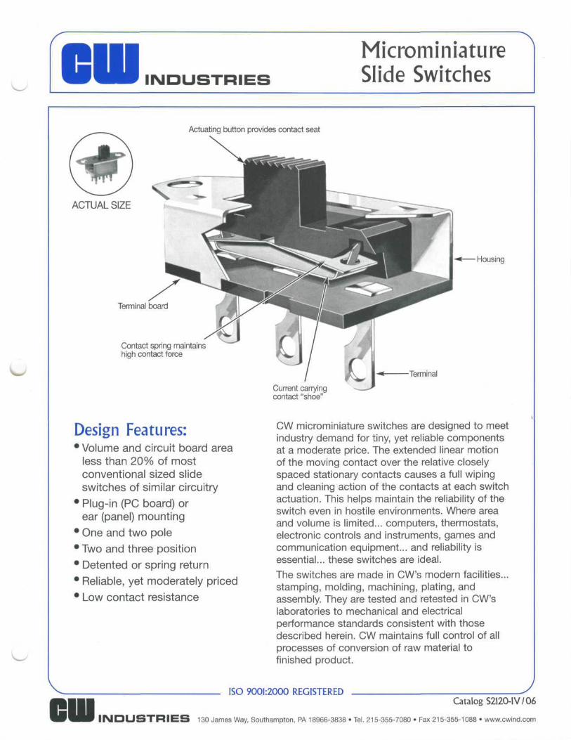
MicrominiatureSlide Switches
Actuating button provides contact seat
ACTUAL SIZE
Terminal board
Contact spring maintainshigh contact force
Design Features:•Volume and circuit board area
less than 20% of mostconventional sized slideswitches of similar circuitry
• Plug-in (PC board) orear (panel) mounting
• One and two pole
• Two and three position
• Detented or spring return
• Reliable, yet moderately priced
• Low contact resistance
• Housing
Terminal
Current carryingcontact "shoe"
CW microminiature switches are designed to meetindustry demand for tiny, yet reliable componentsat a moderate price. The extended linear motionof the moving contact over the relative closelyspaced stationary contacts causes a full wipingand cleaning action of the contacts at each switchactuation. This helps maintain the reliability of theswitch even in hostile environments. Where areaand volume is limited... computers, thermostats,electronic controls and instruments, games andcommunication equipment... and reliability isessential... these switches are ideal.The switches are made in CW's modern facilities...stamping, molding, machining, plating, andassembly. They are tested and retested in CW'slaboratories to mechanical and electricalperformance standards consistent with thosedescribed herein. CW maintains full control of allprocesses of conversion of raw material tofinished product.
ISO 9001:2000 REGISTEREDCatalog S2120-IV/06
INDUSTRIES 130 James Way, Southampton, PA 18966-3838 • Tel. 215-355-7080 • Fax 215-355-1088 • www.cwind.com
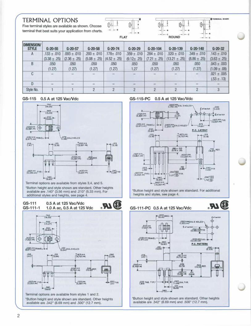
TERMINAL OPTIONSFive terminal styles are available as shown. Choose
terminal that best suits your application from charts.
FLAT ROUND
TERMINAL IDAHO
P
DIMENSION/STYLE
A
B
C
D
Style No.
G-20-55
.133 ±.010
(3.38 ± .25)
.050
(1.27)
—
-
1
G-20-57
.093 ±.010
(2.36 ± .25)
.050
(1.27)
—
-
1
G-20-58
.200 ±.010
(5.08 ± .25)
.050
(1.27)
—
-
2
G-20-74
.178+ .010
(4.52 ± .25)
.050
(1.27)
—
-
2
G-20-29
.359 ±.010
(9.12±.25)
.050
1.27
—
-
2
G-20-104
.284 ±.010
(7.21 ± .25)
.050
(1.27)
—
-
2
G-20-139
.520 ±.010
(13.21 ±.25)
.050
(1.27)
—
-
2
G-20-140
.349 ±.010
(8.86 ± .25)
.050
(1.27)
—
-
2
G-20-32
.143 ±.010
(3.63 ± .25)
.043 ± .003
(1.09 ±.08)
.021 ± .005
(.53 ±.13)
-
3
GS-115 0.5 A at 125 Vac/Vdc
•
* —
H
1.2201.00 '(,-,(5.591.25) \\<r
t
tfSS&T
Cfr
.1201.010 T p .
7i9.9o°5) '_.593 y
(15.06)
[Hjl
w| >-(-p||,DIA.2 HOLES
l__j .125 *.1251.ois u- i .125(3.18) n3.l81.») 13.18)
" i t n(5.081-25) (U.89)REF- | 3yj|
jjj Lj y '; [ Tj
.1431.010 L.043TVD
(3.051.2S)TVR i T (3.631-25) " '-(1.09)""
Terminal options are available from styles 3,4, and 5.
"Button height and style shown are standard. Other heightsavailable are .140" (3.56 mm) and .210" (5.33 mm). Foradditional styles and heights, see page 4.
GS-111 0.5 A at 125 Vac/VdcGS-111-1 1.0 A ac, 0.5 A at 125 Vdc
T7.921.25)
OK&.016(.41)
t
.762 j(19.35)
n.562 j14.27)
&
fRAVE
.1201-010 TYP_(3.051.2»TYR
41 .260 u_^ (6.60) p
1 * I T >
.pJWjU vrt"41
nlf|fgi
-*-4
-~
2"54)D'A'2HOLES
*I874.0I5 .090T4.751.5") T12.29)
I T.228^-010 .548 ,,EF
L____JL____iL.I331X)io JL.020TV[,(3.381.25) "^(.Sl)'"5
Terminal options are available from styles 1 and 2.
'Button height and style shown are standard. Other heightsavailable are .342" (8.69 mm) and .500" (12.7 mm).
GS-115-PC 0.5 A at 125 Vac/Vdc
.040l.02)
.1201 005 TYp
;3.051.0«)"K
"Button height and style shown are standard. For additionalheights and styles, see page 4.
GS-111 -PC 0.5 A at 125 Vac/Vdc
.3121.010(7.92*.'5)
.05|jr)0,A.5HOLESA ~f
*Button height and style shown are standard. Other heightsavailable are .342" (8.69 mm) and .500" (12.7 mm).
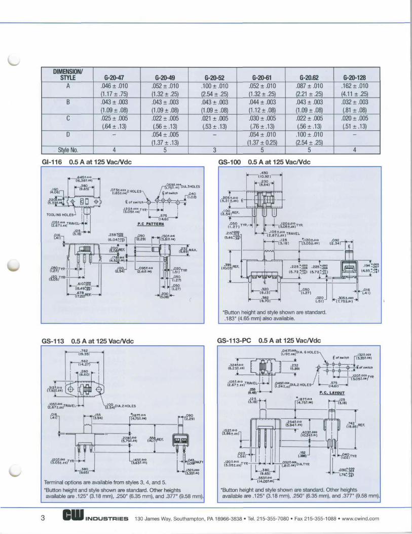
DIMENSION/STYLE
A
B
C
0
Style No.
G-20-47
.046 ±.010(1.1 7 ±75).043 ± .003(1.09 ±.08).025 ± .005(.64 ±.13)
—
4
G-20-49
.052 ±.010(1.32 ±.25).043 ± .003(1.09 ±.08).022 ± .005(.56 ±.13)
.054 ± .005(1.37 ±.13)
5
G-20-52
.100 ±.010(2.54 ± .25).043 ± .003(1.09 ±.08).021 ± .005(.53 ±.13)
—
3
G-20-61
.052 ±.010(1.32 ±.25).044 ± .003(1.1 2 ±.08).030 ± .005(.76 ±.13)
.054 ±.010(1.37 + 0.25)
5
G-20.62
.087 ±.010(2.21 ± .25).043 ± .003(1.09 ±.08).022 ± .005(.56 ±.13).100 ±.010(2.54 ± .25)
5
G-20-128.162 ±.010(4.11 ±.25).032 ± .003(.81 ± .08)
.020 ± .005(.51 ±.13)
—
4
GI-116 0.5 A at 125 Vac/Vdc GS-100 0.5 A at 125 Vac/Vdc
.2051(5.211
I
*I201.0IOr(3.05t.2»)
9PK+.000 99J+.000•"O-.OOB •2Z5-,008
(5.72_' I 9) 15.7 2*^20)
L.05(1.2.050
.27).020(.51)
*Button height and style shown are standard..183" (4.65 mm) also available.
GS-113 0.5 A at 125 Vac/Vdc GS-113-PC 0.5 A at 125 Vac/Vdc
L
.016(.4 in Mp,
n :L ,
iTi:tJU
L .380 ,
_*187t.oi5(4.75±.3»)
m „
I431.0IO13.63L")
ul IPIS^EF. IE
i 1i
Terminal options are available from styles 3, 4, and 5.'Button height and style shown are standard. Other heightsavailable are .125" (3.18 mm), .250" (6.35 mm), and .377" (9.58 mm)
"Button height and style shown are standard. Other heightsavailable are .125" (3.18 mm), .250" (6.35 mm), and .377" (9.58 mm)
INDUSTRIES 130 James Way, Southampton, PA 18966-3838 • Tel. 215-355-7080 • Fax 215-355-1088 • www.cwind.com
DIMENSION/STYLE
A
B
C
D
Style No.
G-20-63
.052 + .010(1.32 ±.25).044 ± .033(1.1 2 ±.08).030 ± .005(.76 ±.13).08 ±.010
(2.03 ± .25)5
G-20-64
.077 ±.010(1.96 ±.25).043 ± .003(1.09 ±.08).025 ± .005(.64 ±.13)
—
4
G-20-73
.052 ±.010(1.32 ±.25).044 ± .003(1.1 2 ±.08).030 ± .005(.76 ±.13).125 ±.005
(3.1 8 ±.13)5
G-20-78
.031 ±.010(.79 ± .25)
.043 ± .003(1.09 ±.08).022 ± .005(.56 ±.13)
.066 ± .005(1.68 ±.13)
5
G-20-85
.243 ±.010(6.1 7 ±.25).043 ± .003(1.09 ±.08).021 ± .005(.53 ±.13)
—
3
G-20-90
.200 ±.010(5.08 ± .25).044 ± .003(1.1 2 ±.08).030 ± .005(.76 ±.13)
.080 ± .005(2.03 ±.13)
5
G-20-95
.286 ±.010(7.26 ± .25).043 ± .003(1.09 ±.08).022 ± .005(.56 ±.13)
.054 ± .005(1.37 ±.13)
5
G-20-102
.145 ±.010(3.68 ± .25).043 ± .003(1.09 ±.08).025 ± .005(.64 ±.13)
—
4
GS-118 0.5 A at 125 Vac/Vdc
Terminal options are available from styles 1 and 2."Button height and style shown are standard. Other heightsavailable are .140" (3.56 mm) and .210" (5.33 mm). Foradditional styles and heights, see below.
GS-118-PC 0.5 A at 125 Vac/Vdc
.020T(.51)
"Button height and style shown are standard. Other heightsavailable are .125" (3.18 mm) and .140" (3.56 mm). Foradditional styles and heights, see below.
Button options... for switches charted only
Button Part No.G-02-239
G-02-284G-02-372 for
use with topperG-02-383
Available"A" Dimension
.125, .140.169.197.147
GS-115X
XX
GS-1 15-0073
X
XX
GS-1 18X
XX
GS-1 18-0008
X
XX
G-02-239 G-02-284 G-02-372
For material specifications, accessories, and how to order, seeback page.
cFc£
Fc
tc
1il
v^
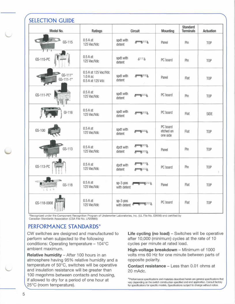
SELECTION GUIDE
Model No.m.m
GS-115
| ^^^^^^^P xGS-115-PC
fill "
^Jfe^GS-nriHpl GS-111-1*
JLGs-m-pc* ir^ff
GS-100 1 =j
^S j GS-113
^^f
GS-113-PC jI ,
1 ' GS-118
GS-1 18-0008 I
Ratings
0.5 A at125Vac/Vdc
0.5 A at125VacA/dc
0.5Aat125Vac/VdcLOAac0.5Aat125Vdc
0.5 A at125Vac/Vdc
0.5 A at125Vac/Vdc
0.5 A at125Vac/Vdc
0.5 A at125Vac/Vdc
0.5 A at125Vac/Vdc
0.5 A at125Vac/Vdc
0.5 A at125Vac/Vdc
Circuit
spdtwith r~~r— -,detent
spdtwith 5— £detent
spdtwith (F™ --detent
spelt with x""t. — a
spdtwith gzzzz£-=idetent
spdtwith T-^T—Ldetent
dpdtwith &*"&—!>detent 3""A--^)
dpdt with «"~fr— *detent ffF1^
sp-3-pos fW0^—^with detent
sp-3-poswith detent
Mounting
Panel
PC board
Panel
PC board
PC board
PC boardetched onone side
Panel
PC board
Panel
PC board
StandardTerminals
Pin
Pin
Flat
Pin
Flat
Flat
Pin
Pin
Flat
Flat
Actuation
TOP
TOP
TOP
TOP
SIDE
TOP
TOP
TOP
TOP
TOP
"Recognized under the Component Recognition Program of Underwriter Laboratories, Inc. (UL File No. E9556) and certified byCanadian Standards Association (CSA File No. LR20985)
PERFORMANCE STANDARDS+
j\N switches are designed and manufactured to Life cycling (no load) - Switches will be operative>erform when subjected to the following after 10,000 (minimum) cycles at the rate of 10onditions: Operating temperature - 104°C cycles per minute at rated load,imbient maximum. High-voltage breakdown - Minimum of 1000Relative humidity - After 1 00 hours in an volts rms 60 Hz for one minute between parts ofitmosphere having 95% relative humidity and a opposite polarity,emperature of 50°C, switches will be operative Contact resistance - Less than 0.01 ohms atind insulation resistance will be greater than 20 mAdc.00 megohms between contacts and housing,: allowed tO drV for a Deriod Of One hOUr at +Performance specifications and materials described herein are general specifications that
vary depending on the switch construction specified and end application. Consult factory5°C (rOOm temperature). for specifications for specific models. Specifications subject to change without notice. J
MATERIALS OF CONSTRUCTIONActuator - Type 6/6 black nylon, othercolors available
Housing - Cold-rolled steel, plated
Housing plating - Panel: zinc, PC board: Electro-tin
Terminal board - N.E.M.A. Grade XPPhenolic Laminate
Terminals - Copper, silver-plated
Moving contact - Copper alloys, silver-plated
Contact spring - Beryllium copper orphosphor bronze"""Materials described herein are general specifications that vary dependingon the switch construction specified and end application. Consult factoryfor specifications for specific models. Specifications subject to changewithout notice.
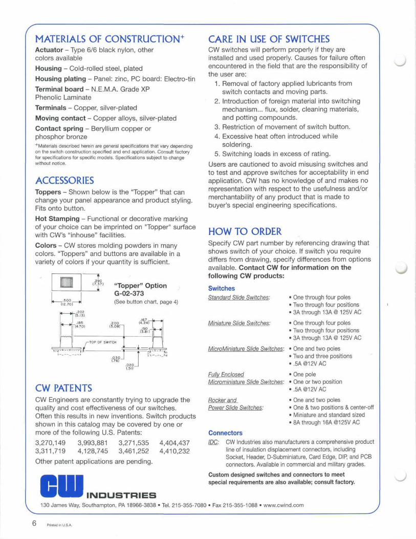
ACCESSORIESToppers - Shown below is the "Topper" that canchange your panel appearance and product styling.Fits onto button.
Hot Stamping - Functional or decorative markingof your choice can be imprinted on "Topper" surfacewith CW's "inhouse" facilities.
Colors - CW stores molding powders in manycolors. "Toppers" and buttons are available in avariety of colors if your quantity is sufficient.
_.500_(12.70)
.290
?7) "Topper" OptionG-02-373(See button chart, page 4)
1 ^
< »
» — »
"
(5.13)
.185"(4.70)
---fi-
.200(5.08)~~
-TOP OF SWITCH
.030_
.167 _J(4.24)
.150 _(3.81)
^ 1 ^-L
« »
« — »
~'v-
.020_(.51)
CW PATENTSCW Engineers are constantly trying to upgrade thequality and cost effectiveness of our switches.Often this results in new inventions. Switch productsshown in this catalog may be covered by one ormore of the following U.S. Patents:
3,270,149 3,993,881 3,271,535 4,404,4373,311,719 4,128,745 3,461,252 4,410,232
Other patent applications are pending.
CARE IN USE OF SWITCHESCW switches will perform properly if they areinstalled and used properly. Causes for failure oftenencountered in the field that are the responsibility ofthe user are:
1. Removal of factory applied lubricants fromswitch contacts and moving parts.
2. Introduction of foreign material into switchingmechanism... flux, solder, cleaning materials,and potting compounds.
3. Restriction of movement of switch button.4. Excessive heat often introduced while
soldering.5. Switching loads in excess of rating.
Users are cautioned to avoid misusing switches andto test and approve switches for acceptability in endapplication. CW has no knowledge of and makes norepresentation with respect to the usefulness and/ormerchantability of any product that is made tobuyer's special engineering specifications.
HOW TO ORDERSpecify CW part number by referencing drawing thatshows switch of your choice. If switch you requirediffers from drawing, specify differences from optionsavailable. Contact CW for information on thefollowing CW products:
SwitchesStandard Slide Switches:
Miniature Slide Switches:
MicroMiniature Slide Switches:
Fully EnclosedMicrominiature Slide Switches:
• One through four poles• Two through four positions• 3A through 13A@ 125V AC
• One through four poles• Two through four positions• 3A through 13A@ 125V AC
• One and two poles• Two and three positions•.5AO12VAC
• One pole• One or two position«.5A@12VAC
Rocker andPower Slide Switches:
• One and two poles• One & two positions & center-off• Miniature and standard sized• 8A through 16A@125V AC
ConnectorsIDC: CW Industries also manufacturers a comprehensive product
line of insulation displacement connectors, includingSocket, Header, D-Subminiature, Card Edge, DIP, and PCBconnectors. Available in commercial and military grades.
Custom designed switches and connectors to meetspecial requirements are also available; consult factory.
INDUSTRIES130 James Way, Southampton, PA 18966-3838 • Tel. 215-355-7080 • Fax 215-355-1088 • www.cwind.com
Printed in U.S.A.