Embed Size (px)
Citation preview

Product Data SheetPS-00400, Rev X
January 2020
Micro Motion™ 1000 and 2000 Transmitterswith MVD™ Technology
Advanced architecture with flexible installation options
■ Integral or remote mounting provides maximum flexibility
■ Cost-effective 4-wire interface reduces installation costs
■ Remote field mount models available with stainless steel housing for harsherenvironments
■ DIN rail option reduces complexity and increases versatility
VIEW PRODUCT >
Wide variety of I/O and application capabilities to fit your needs
■ High-speed DSP for accuracy under the toughest conditions—entrained gas, high noise, high turndown,and more
■ Concentration and net flow measurement eliminate the need for additional instruments
■ Approved for custody transfer and certified for SIL2 and SIL3, which provides measurement confidenceand reliability
■ WirelessHART® option allows you to gain access to additional diagnostics and process informationwithout added wiring costs
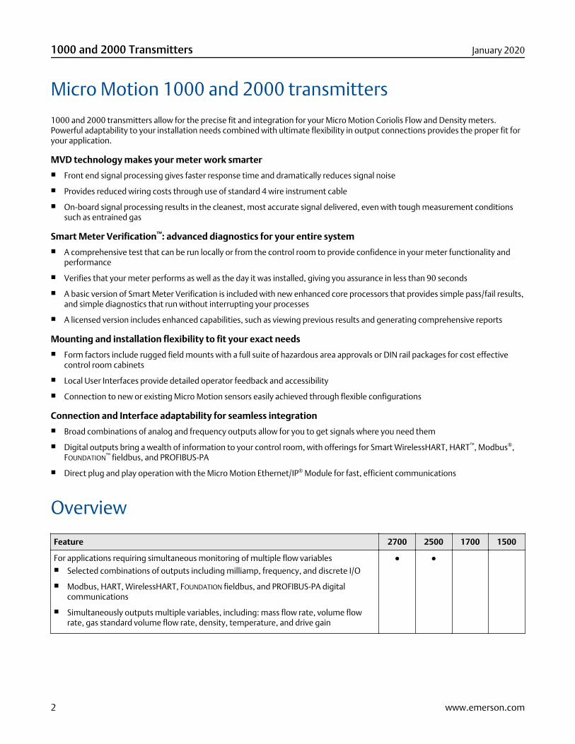
Micro Motion 1000 and 2000 transmitters1000 and 2000 transmitters allow for the precise fit and integration for your Micro Motion Coriolis Flow and Density meters.Powerful adaptability to your installation needs combined with ultimate flexibility in output connections provides the proper fit foryour application.
MVD technology makes your meter work smarter■ Front end signal processing gives faster response time and dramatically reduces signal noise
■ Provides reduced wiring costs through use of standard 4 wire instrument cable
■ On-board signal processing results in the cleanest, most accurate signal delivered, even with tough measurement conditionssuch as entrained gas
Smart Meter Verification™: advanced diagnostics for your entire system■ A comprehensive test that can be run locally or from the control room to provide confidence in your meter functionality and
performance
■ Verifies that your meter performs as well as the day it was installed, giving you assurance in less than 90 seconds
■ A basic version of Smart Meter Verification is included with new enhanced core processors that provides simple pass/fail results,and simple diagnostics that run without interrupting your processes
■ A licensed version includes enhanced capabilities, such as viewing previous results and generating comprehensive reports
Mounting and installation flexibility to fit your exact needs■ Form factors include rugged field mounts with a full suite of hazardous area approvals or DIN rail packages for cost effective
control room cabinets
■ Local User Interfaces provide detailed operator feedback and accessibility
■ Connection to new or existing Micro Motion sensors easily achieved through flexible configurations
Connection and Interface adaptability for seamless integration■ Broad combinations of analog and frequency outputs allow for you to get signals where you need them
■ Digital outputs bring a wealth of information to your control room, with offerings for Smart WirelessHART, HART™, Modbus®,FOUNDATION™ fieldbus, and PROFIBUS-PA
■ Direct plug and play operation with the Micro Motion Ethernet/IP® Module for fast, efficient communications
Overview
Feature 2700 2500 1700 1500
For applications requiring simultaneous monitoring of multiple flow variables■ Selected combinations of outputs including milliamp, frequency, and discrete I/O
■ Modbus, HART, WirelessHART, FOUNDATION fieldbus, and PROFIBUS-PA digitalcommunications
■ Simultaneously outputs multiple variables, including: mass flow rate, volume flowrate, gas standard volume flow rate, density, temperature, and drive gain
● ●
1000 and 2000 Transmitters January 2020
2 www.emerson.com
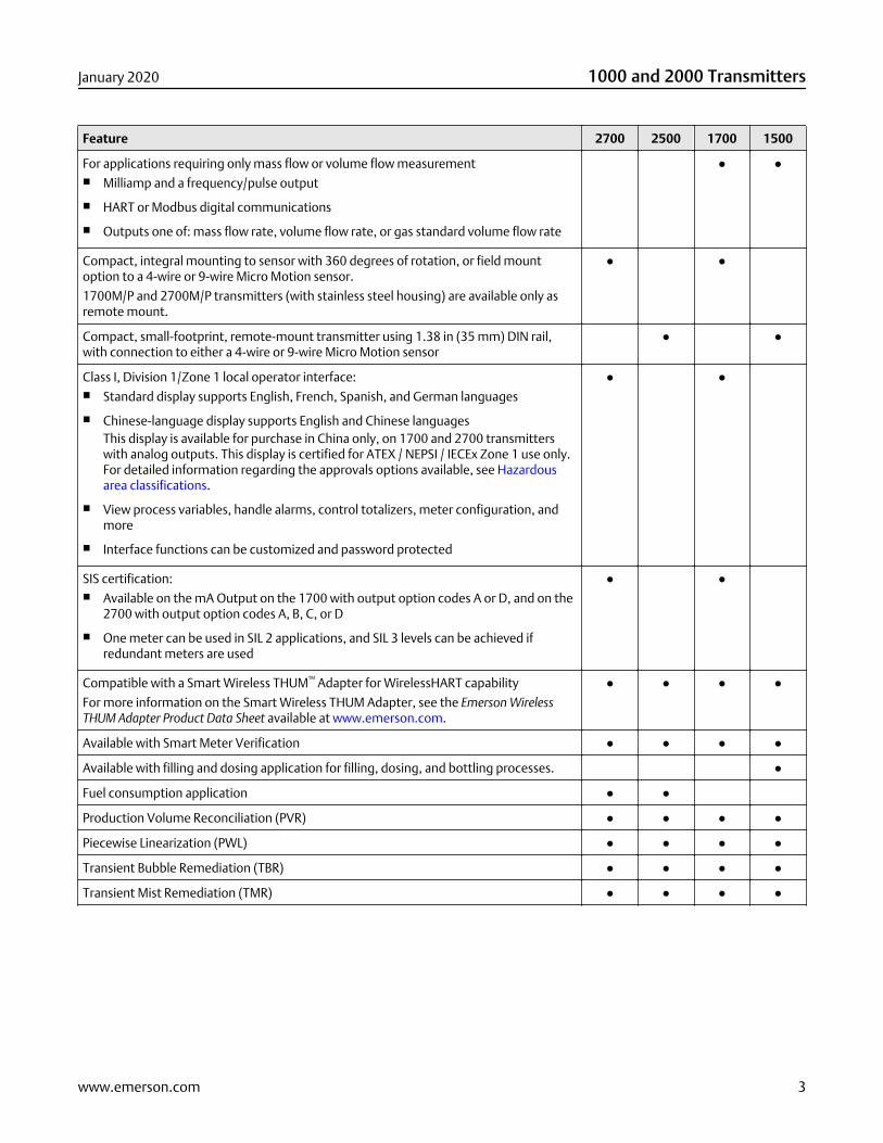
Feature 2700 2500 1700 1500
For applications requiring only mass flow or volume flow measurement■ Milliamp and a frequency/pulse output
■ HART or Modbus digital communications
■ Outputs one of: mass flow rate, volume flow rate, or gas standard volume flow rate
● ●
Compact, integral mounting to sensor with 360 degrees of rotation, or field mountoption to a 4-wire or 9-wire Micro Motion sensor.
1700M/P and 2700M/P transmitters (with stainless steel housing) are available only asremote mount.
● ●
Compact, small-footprint, remote-mount transmitter using 1.38 in (35 mm) DIN rail,with connection to either a 4-wire or 9-wire Micro Motion sensor
● ●
Class I, Division 1/Zone 1 local operator interface:■ Standard display supports English, French, Spanish, and German languages
■ Chinese-language display supports English and Chinese languagesThis display is available for purchase in China only, on 1700 and 2700 transmitterswith analog outputs. This display is certified for ATEX / NEPSI / IECEx Zone 1 use only.For detailed information regarding the approvals options available, see Hazardousarea classifications.
■ View process variables, handle alarms, control totalizers, meter configuration, andmore
■ Interface functions can be customized and password protected
● ●
SIS certification:■ Available on the mA Output on the 1700 with output option codes A or D, and on the
2700 with output option codes A, B, C, or D
■ One meter can be used in SIL 2 applications, and SIL 3 levels can be achieved ifredundant meters are used
● ●
Compatible with a Smart Wireless THUM™ Adapter for WirelessHART capability
For more information on the Smart Wireless THUM Adapter, see the Emerson WirelessTHUM Adapter Product Data Sheet available at www.emerson.com.
● ● ● ●
Available with Smart Meter Verification ● ● ● ●
Available with filling and dosing application for filling, dosing, and bottling processes. ●
Fuel consumption application ● ●
Production Volume Reconciliation (PVR) ● ● ● ●
Piecewise Linearization (PWL) ● ● ● ●
Transient Bubble Remediation (TBR) ● ● ● ●
Transient Mist Remediation (TMR) ● ● ● ●
January 2020 1000 and 2000 Transmitters
www.emerson.com 3

ApplicationsApplication are custom designed programs and software available to offer additional functionality and performance totransmitters. These applications are available through options in the transmitter model code, see the ordering information sectionfor details.
Smart Meter Verification (SMV)■ Provides a quick, complete assessment of a Coriolis meter, determining whether the meter has been affected by erosion,
corrosion, or other influences affecting meter calibration.
■ No secondary references are required to perform this operation, and the meter can continue normal process measurementwhile the test is in progress.
■ A basic version of Smart Meter Verification is included with new enhanced core processors that provides simple pass/fail results,and simple diagnostics that run without interrupting your processes.
Discrete batch control■ Simple batch control based on totalizer values
■ For transmitters with analog or intrinsically safe outputs, the Frequency Output can be configured as a Discrete Output.
■ For transmitters with configurable I/O, a channel can be configured as a Discrete Output.
Weights & Measures custody transfer■ Physical and software security
■ Security-alarm posting
■ Mass or volume totalizer that can be configured by the user
■ Compliant with MID 2014/32/EU Annex MI-005
■ Certified by NTEP and OIML
Concentration measurement
Provides concentration measurement based on either industry-specific or liquid-specific units and relationships. Standardmeasurement options include:
■ Industry-specific:— °Brix
— °Plato
— °Balling
— °Baumé at SG60/60
— Specific gravity
■ Liquid-specific:— %HFCS
— Concentration derived from reference density
— Concentration derived from specific gravity
Additionally, the application can be customized for site-specific concentration measurement (such as %HNO3 , %NaOH).
1000 and 2000 Transmitters January 2020
4 www.emerson.com

Petroleum measurement
Adds the following calculations to the standard software:
■ Calculates base density (corrected API Gravity) and Ctl (the correction for the effect of temperature on a liquid)
■ Calculates gross volume at standard temperature
■ Calculates flow-weighted average temperature and flow-weighted average observed gravity (flowing density)
Fuel consumption■ Automatically calculates the fluid consumption between two Coriolis flow sensors, typically for recirculating fuel consumption
loops
■ Eliminates the need to program an external calculation system and minimizes common inaccuracies related to time lag,sampling issues and cumulative errors
■ Uses a proprietary algorithm that adapts to the unique calibration of each pair of Coriolis flow sensors
Production Volume Reconciliation (PVR)■ Provides oil and water volumes through density-based calculations for both line and reference conditions
■ Detects bubble entrainment or flashing in the sensor, and can correct volumes accordingly
■ Best for undersized three-phase separators that frequently have intermittent gas or water contamination in the oil leg
■ Offers a simple, low-cost solution for net oil and net water measurement for two-phase separators
Transient Bubble Remediation (TBR)■ Used with single-component liquid streams that may experience intermittent low levels of gas entrainment, that is, gas
carryunder
■ Enables accurate measurement of a single fluid during periods of entrained gas by providing a substitute density value based onthe immediately preceding process density (standard configuration)
■ Tracks total time of aerated flow to assist in diagnosing process issues that may cause aeration
Transient Mist Remediation (TMR)■ Used with gas streams that may experience intermittent low levels of liquid entrainment, i.e., liquid carry-over
■ Allows gas measurement to continue during periods of entrained liquid (mist) by providing a substitute flow rate value basedon the immediately preceding process flow rate
■ Returns to reporting the measured flow rate when the mist interval is over, increased or decreased by a maximum of 10%, untilflow totals are appropriately adjusted for the unmeasured flow
■ Provides an indication of the amount of time that liquid was present in the stream — identifying process improvements toreduce gas stream contamination
Piecewise Linearization (PWL) for enhanced gas applications■ Provides gas calibration enhancement capability for industry-leading gas measurement performance
■ Designed specifically for midstream natural gas fiscal metering applications
Third-party gas calibration services are not included.
January 2020 1000 and 2000 Transmitters
www.emerson.com 5
Electrical connections
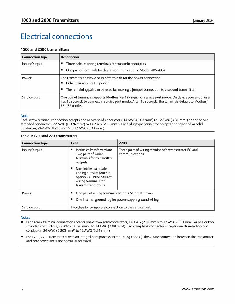
1500 and 2500 transmitters
Connection type Description
Input/Output ■ Three pairs of wiring terminals for transmitter outputs
■ One pair of terminals for digital communications (Modbus/RS-485)
Power The transmitter has two pairs of terminals for the power connection:■ Either pair accepts DC power
■ The remaining pair can be used for making a jumper connection to a second transmitter
Service port One pair of terminals supports Modbus/RS-485 signal or service port mode. On device power-up, userhas 10 seconds to connect in service port mode. After 10 seconds, the terminals default to Modbus/RS-485 mode.
NoteEach screw terminal connection accepts one or two solid conductors, 14 AWG (2.08 mm²) to 12 AWG (3.31 mm²) or one or twostranded conductors, 22 AWG (0.326 mm²) to 14 AWG (2.08 mm²). Each plug type connector accepts one stranded or solidconductor, 24 AWG (0.205 mm²) to 12 AWG (3.31 mm²).
Table 1: 1700 and 2700 transmitters
Connection type 1700 2700
Input/Output ■ Intrinsically safe version:Two pairs of wiringterminals for transmitteroutputs
■ Non-intrinsically safeanalog outputs (outputoption A): Three pairs ofwiring terminals fortransmitter outputs
Three pairs of wiring terminals for transmitter I/O andcommunications
Power ■ One pair of wiring terminals accepts AC or DC power
■ One internal ground lug for power-supply ground wiring
Service port Two clips for temporary connection to the service port
Notes■ Each screw terminal connection accepts one or two solid conductors, 14 AWG (2.08 mm²) to 12 AWG (3.31 mm²) or one or two
stranded conductors, 22 AWG (0.326 mm²) to 14 AWG (2.08 mm²). Each plug type connector accepts one stranded or solidconductor, 24 AWG (0.205 mm²) to 12 AWG (3.31 mm²).
■ For 1700/2700 transmitters with an integral core processor (mounting code C), the 4-wire connection between the transmitterand core processor is not normally accessed.
1000 and 2000 Transmitters January 2020
6 www.emerson.com
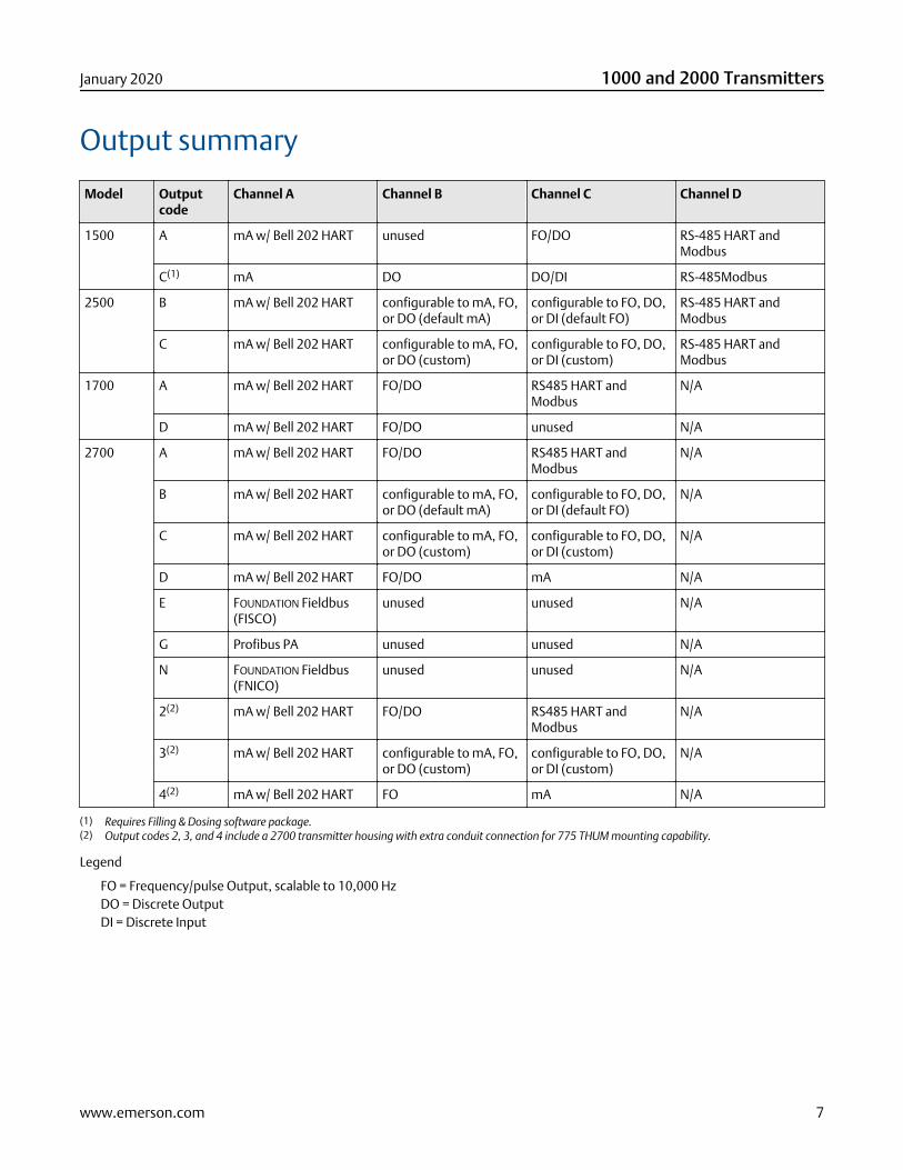
Output summary
Model Outputcode
Channel A Channel B Channel C Channel D
1500 A mA w/ Bell 202 HART unused FO/DO RS-485 HART andModbus
C(1) mA DO DO/DI RS-485Modbus
2500 B mA w/ Bell 202 HART configurable to mA, FO,or DO (default mA)
configurable to FO, DO,or DI (default FO)
RS-485 HART andModbus
C mA w/ Bell 202 HART configurable to mA, FO,or DO (custom)
configurable to FO, DO,or DI (custom)
RS-485 HART andModbus
1700 A mA w/ Bell 202 HART FO/DO RS485 HART andModbus
N/A
D mA w/ Bell 202 HART FO/DO unused N/A
2700 A mA w/ Bell 202 HART FO/DO RS485 HART andModbus
N/A
B mA w/ Bell 202 HART configurable to mA, FO,or DO (default mA)
configurable to FO, DO,or DI (default FO)
N/A
C mA w/ Bell 202 HART configurable to mA, FO,or DO (custom)
configurable to FO, DO,or DI (custom)
N/A
D mA w/ Bell 202 HART FO/DO mA N/A
E FOUNDATION Fieldbus(FISCO)
unused unused N/A
G Profibus PA unused unused N/A
N FOUNDATION Fieldbus(FNICO)
unused unused N/A
2(2) mA w/ Bell 202 HART FO/DO RS485 HART andModbus
N/A
3(2) mA w/ Bell 202 HART configurable to mA, FO,or DO (custom)
configurable to FO, DO,or DI (custom)
N/A
4(2) mA w/ Bell 202 HART FO mA N/A
(1) Requires Filling & Dosing software package.(2) Output codes 2, 3, and 4 include a 2700 transmitter housing with extra conduit connection for 775 THUM mounting capability.
Legend
FO = Frequency/pulse Output, scalable to 10,000 HzDO = Discrete OutputDI = Discrete Input
January 2020 1000 and 2000 Transmitters
www.emerson.com 7
Input/output signal detail
All codes
Inputs for all codes:
■ With mounting codes R, M, and B: One 4-wire sensor signal input connection, intrinsically safe
■ With mounting codes C and P (9-wire remote transmitter): One 9-wire sensor signal input connection, intrinsically safe
Output code A or 2These codes are for non-intrinsically safe mA Output (with HART and Modbus) for 1500, 1700, and 2700 transmitters.
One active 4-20 mA Output■ Not intrinsically safe
■ Isolated to ±50 VDC from all other outputs and earth ground
■ Maximum load limit: 820 ohms
■ 1500 and 1700 can report mass flow or volume flow
■ 2700 can report mass flow, volume flow, density, temperature, or drive gain
■ Output is linear with process from 3.8 to 20.5 mA, per NAMUR NE 43 (February 2003)
One active FO/pulse output■ Not intrinsically safe
■ Can report mass flow or volume flow, which can be used to indicate flow rate or total
■ For 1500 and 1700, Frequency Output reports the same flow variable as the mA Output
■ For 2700, Frequency Output is independent of mA Output
■ Scalable to 10,000 Hz
■ For 1500 and 2500, output voltage is +15 VDC ±3% with a 2.2 kohm internal pull-up resistor
■ For 1700 and 2700, output voltage is +24 VDC ±3% with a 2.2 kohm internal pull-up resistor
■ Output is linear with flow rate to 12,500 Hz
■ Configurable polarity: active high or active low
■ 1700 Discrete Output: Can be configured as a Discrete Output to report flow direction and flow switch
■ 2700 Discrete Output: Can be configured as a Discrete Output to report 5 discrete events, flow direction, flow switch,calibration in progress, or fault.
■ On 1700 and 2700 transmitters, this can also be configured as a Discrete Output
Output codes B, C, and 3These codes are for non-intrinsically safe configurable output 2500 and 2700 transmitters. The transmitter has a total of 3configurable inputs/outputs. Refer to the following data for the ways that these 3 inputs/outputs can be configured.
One or two active 4–20 mAO■ Not intrinsically safe
■ Isolated to ±50 VDC from all other outputs and earth ground
1000 and 2000 Transmitters January 2020
8 www.emerson.com
■ Maximum load limit of mA1: 820 ohms; of mA2: 420 ohms
■ Can report mass flow, volume flow, density, temperature, or drive gain
■ Output is linear with process from 3.8 to 20.5 mA, per NAMUR NE 43 (February 2003)
One or two active or passive FOs/pulse outputs■ Not intrinsically safe
■ Can report mass flow or volume flow, which can be used to indicate flow rate or total
■ If configured as a dual pulse output, the channels are electrically isolated but not independent (see custody transfer notebelow)
■ Scalable to 10,000 Hz
■ If active, output voltage is +15 VDC ±3% with a 2.2 kohm internal pull-up resistor
■ If passive, output voltage is 30 VDC maximum, 24 VDC typical, sinking up to 500 mA at 30 VDC.
■ Output is linear with flow rate to 12,500 Hz
One or two active or passive DOs■ Not intrinsically safe
■ Can report 5 discrete events, flow switch, forward/reverse flow, calibration in progress, or fault
■ If active, output voltage is +15 VDC ±3% with a 2.2 kohm internal pull-up resistor
■ If passive, output voltage is 30 VDC maximum, 24 VDC typical, sinking up to 500 mA at 30 VDC
One DI■ Can be configured for active or passive power
■ Not intrinsically safe
■ Active power +15 VDC, 7 mA maximum source current
■ Passive power +3–30 VDC maximum
■ Can start/stop totals and inventories, reset all totals, reset mass total, reset volume total, start sensor zero, or initiate multipleactions
For custody transfer using double-pulse Frequency Output, the transmitter can be configured for 2 Frequency Outputs. The secondoutput can be phase-shifted –90, 0, 90, or 180 degrees from the first output, or the dual-pulse output can be set to quadraturemode.
Output codes E and GThese codes are for intrinsically safe FOUNDATION fieldbus and PROFIBUS-PA 2700 transmitters.
One FOUNDATION fieldbus H1 or PROFIBUS-PA output■ FOUNDATION fieldbus and PROFIBUS-PA wiring is intrinsically safe with an intrinsically safe power supply
■ The transmitter fieldbus circuit is passive, and draws power from the fieldbus segment. Current draw from the fieldbus segmentis 13 mA
■ Manchester-encoded digital signal conforms to IEC 61158-2
■ Entity parameters:— Ui = 30 VDC
— Ii = 300 mA
— Pi = 1,3 W
January 2020 1000 and 2000 Transmitters
www.emerson.com 9
— Ci = negligible
— Li = negligible
Output code NThese codes are for non-incendive FOUNDATION fieldbus transmitters.
One FOUNDATION fieldbus H1 output■ FOUNDATION fieldbus wiring is non-incendive
■ The transmitter fieldbus circuit is passive, and draws power from the fieldbus segment. Current draw from the fieldbus segmentis 13 mA
■ Manchester-encoded digital signal conforms to IEC 61158-2
■ Entity parameters:— Ui = 30 VDC
— Ii = 300 mA
— Pi = 1,3 W
— Ci = negligible
— Li = negligible
Output codes D and 4These codes are for intrinsically safe 1700 and 2700 transmitters.
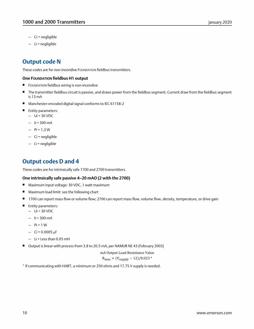
One intrinsically safe passive 4–20 mAO (2 with the 2700)■ Maximum input voltage: 30 VDC, 1 watt maximum
■ Maximum load limit: see the following chart
■ 1700 can report mass flow or volume flow; 2700 can report mass flow, volume flow, density, temperature, or drive gain
■ Entity parameters:— Ui = 30 VDC
— Ii = 300 mA
— Pi = 1 W
— Ci = 0.0005 µF
— Li = Less than 0.05 mH
■ Output is linear with process from 3.8 to 20.5 mA, per NAMUR NE 43 (February 2003)mA Output Load Resistance ValueRmax = (Vsupply − 12)/0.023 ** If communicating with HART, a minimum or 250 ohms and 17.75 V supply is needed.
1000 and 2000 Transmitters January 2020
10 www.emerson.com
0
100
200
300
400
500
600
700
800
900
1000
12 14 16 18 20 22 24 26 28 30
A
B
C
A. External resistor (ohms)B. Operating regionC. Supply voltage (volts)
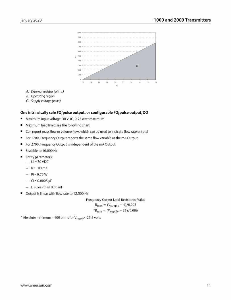
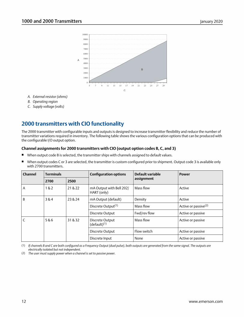
One intrinsically safe FO/pulse output, or configurable FO/pulse output/DO■ Maximum input voltage: 30 VDC, 0.75 watt maximum
■ Maximum load limit: see the following chart
■ Can report mass flow or volume flow, which can be used to indicate flow rate or total
■ For 1700, Frequency Output reports the same flow variable as the mA Output
■ For 2700, Frequency Output is independent of the mA Output
■ Scalable to 10,000 Hz
■ Entity parameters:— Ui = 30 VDC
— Ii = 100 mA
— Pi = 0.75 W
— Ci = 0.0005 µF
— Li = Less than 0.05 mH
■ Output is linear with flow rate to 12,500 HzFrequency Output Load Resistance ValueRmax = (Vsupply − 4)/0.003*Rmin = (Vsupply − 25)/0.006* Absolute minimum = 100 ohms for Vsupply < 25.6 volts
January 2020 1000 and 2000 Transmitters
www.emerson.com 11
0
1000
2000
3000
4000
5000
6000
7000
8000
9000
10000
5 7 9 11 13 15 17 19 21 23 25 27 29
A
B
C
A. External resistor (ohms)B. Operating regionC. Supply voltage (volts)
2000 transmitters with CIO functionalityThe 2000 transmitter with configurable inputs and outputs is designed to increase transmitter flexibility and reduce the number oftransmitter variations required in inventory. The following table shows the various configuration options that can be produced withthe configurable I/O output option.
Channel assignments for 2000 transmitters with CIO (output option codes B, C, and 3)■ When output code B is selected, the transmitter ships with channels assigned to default values.
■ When output codes C or 3 are selected, the transmitter is custom configured prior to shipment. Output code 3 is available onlywith 2700 transmitters.
Channel Terminals Configuration options Default variableassignment
Power
2700 2500
A 1 & 2 21 & 22 mA Output with Bell 202/HART (only)
Mass flow Active
B 3 & 4 23 & 24 mA Output (default) Density Active
Discrete Output(1) Mass flow Active or passive(2)
Discrete Output Fwd/rev flow Active or passive
C 5 & 6 31 & 32 Discrete Output(default)(1)
Mass flow Active or passive
Discrete Output Flow switch Active or passive
Discrete Input None Active or passive
(1) If channels B and C are both configured as a Frequency Output (dual pulse), both outputs are generated from the same signal. The outputs areelectrically isolated but not independent.
(2) The user must supply power when a channel is set to passive power.
1000 and 2000 Transmitters January 2020
12 www.emerson.com
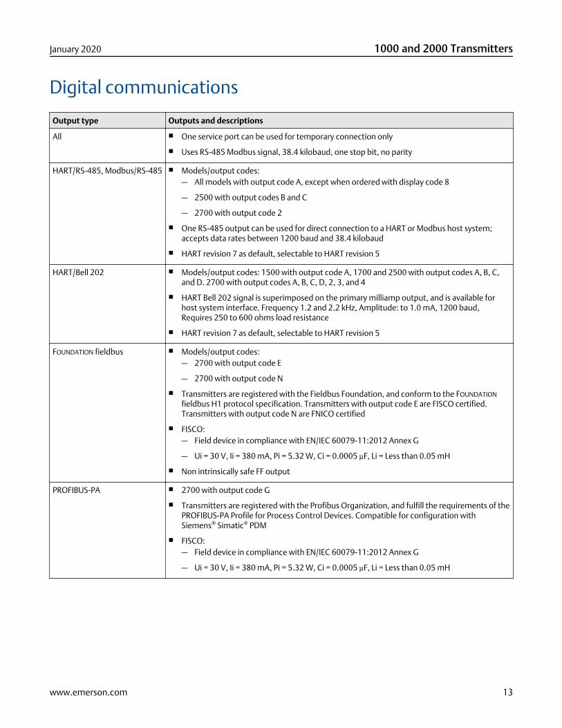
Digital communications
Output type Outputs and descriptions
All ■ One service port can be used for temporary connection only
■ Uses RS-485 Modbus signal, 38.4 kilobaud, one stop bit, no parity
HART/RS-485, Modbus/RS-485 ■ Models/output codes:— All models with output code A, except when ordered with display code 8
— 2500 with output codes B and C
— 2700 with output code 2
■ One RS-485 output can be used for direct connection to a HART or Modbus host system;accepts data rates between 1200 baud and 38.4 kilobaud
■ HART revision 7 as default, selectable to HART revision 5
HART/Bell 202 ■ Models/output codes: 1500 with output code A, 1700 and 2500 with output codes A, B, C,and D. 2700 with output codes A, B, C, D, 2, 3, and 4
■ HART Bell 202 signal is superimposed on the primary milliamp output, and is available forhost system interface. Frequency 1.2 and 2.2 kHz, Amplitude: to 1.0 mA, 1200 baud,Requires 250 to 600 ohms load resistance
■ HART revision 7 as default, selectable to HART revision 5
FOUNDATION fieldbus ■ Models/output codes:— 2700 with output code E
— 2700 with output code N
■ Transmitters are registered with the Fieldbus Foundation, and conform to the FOUNDATION
fieldbus H1 protocol specification. Transmitters with output code E are FISCO certified.Transmitters with output code N are FNICO certified
■ FISCO:— Field device in compliance with EN/IEC 60079-11:2012 Annex G
— Ui = 30 V, Ii = 380 mA, Pi = 5.32 W, Ci = 0.0005 µF, Li = Less than 0.05 mH
■ Non intrinsically safe FF output
PROFIBUS-PA ■ 2700 with output code G
■ Transmitters are registered with the Profibus Organization, and fulfill the requirements of thePROFIBUS-PA Profile for Process Control Devices. Compatible for configuration withSiemens® Simatic® PDM
■ FISCO:— Field device in compliance with EN/IEC 60079-11:2012 Annex G
— Ui = 30 V, Ii = 380 mA, Pi = 5.32 W, Ci = 0.0005 µF, Li = Less than 0.05 mH
January 2020 1000 and 2000 Transmitters
www.emerson.com 13
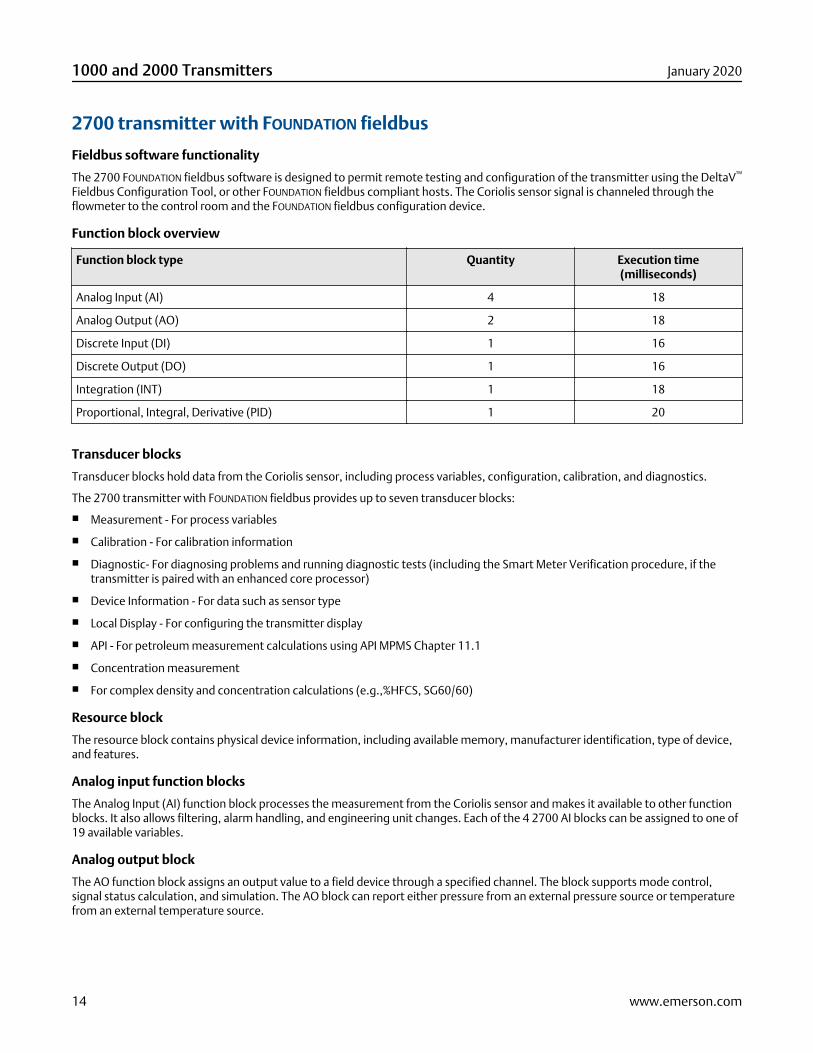
2700 transmitter with FOUNDATION fieldbus
Fieldbus software functionality
The 2700 FOUNDATION fieldbus software is designed to permit remote testing and configuration of the transmitter using the DeltaV™
Fieldbus Configuration Tool, or other FOUNDATION fieldbus compliant hosts. The Coriolis sensor signal is channeled through theflowmeter to the control room and the FOUNDATION fieldbus configuration device.
Function block overview
Function block type Quantity Execution time(milliseconds)
Analog Input (AI) 4 18
Analog Output (AO) 2 18
Discrete Input (DI) 1 16
Discrete Output (DO) 1 16
Integration (INT) 1 18
Proportional, Integral, Derivative (PID) 1 20
Transducer blocks
Transducer blocks hold data from the Coriolis sensor, including process variables, configuration, calibration, and diagnostics.
The 2700 transmitter with FOUNDATION fieldbus provides up to seven transducer blocks:
■ Measurement - For process variables
■ Calibration - For calibration information
■ Diagnostic- For diagnosing problems and running diagnostic tests (including the Smart Meter Verification procedure, if thetransmitter is paired with an enhanced core processor)
■ Device Information - For data such as sensor type
■ Local Display - For configuring the transmitter display
■ API - For petroleum measurement calculations using API MPMS Chapter 11.1
■ Concentration measurement
■ For complex density and concentration calculations (e.g.,%HFCS, SG60/60)
Resource block
The resource block contains physical device information, including available memory, manufacturer identification, type of device,and features.
Analog input function blocks
The Analog Input (AI) function block processes the measurement from the Coriolis sensor and makes it available to other functionblocks. It also allows filtering, alarm handling, and engineering unit changes. Each of the 4 2700 AI blocks can be assigned to one of19 available variables.
Analog output block
The AO function block assigns an output value to a field device through a specified channel. The block supports mode control,signal status calculation, and simulation. The AO block can report either pressure from an external pressure source or temperaturefrom an external temperature source.
1000 and 2000 Transmitters January 2020
14 www.emerson.com
Discrete Input block
One permanent Discrete Input (DI) function block can be assigned to any of the discrete input variable channels in the transducerblock. The DI block channels are: forward/reverse indication, zero in progress, fault condition indication, and meter verificationfailure.
Discrete Output block
One permanent Discrete Output (DO) function block can be assigned to any of the Discrete Output variable channels in thetransducer block. The DO block channels are: start sensor zero, reset mass total, reset volume total, reset API reference (standard)volume total, reset all process totals, reset concentration measurement reference volume total, reset concentration measurementnet mass total, reset concentration measurement net volume total, start/stop all totals, increment concentration measurementcurve, reset gas standard volume total, and start meter verification in continuous measurement mode.
Proportional integral derivative block
The optional proportional integral derivative (PID) function block combines all the necessary logic to perform proportional/integral/derivative control. The block supports mode control, signal scaling and limiting, feed forward control, override tracking,alarm limit detection, and signal status propagation.
Integrator block
The integrator block provides functionality for the transmitter totalizers. Any process total can be selected and reset.
Diagnostics and service
2700 transmitters automatically perform continuous self diagnostics. Using the Diagnostic transducer block, the user can performon-line testing of the transmitter and sensor. Diagnostics are event driven and do not require polling for access.
PlantWeb™ Field Diagnostic is supported. The diagnostic information is based on NAMUR NE 107 standard.
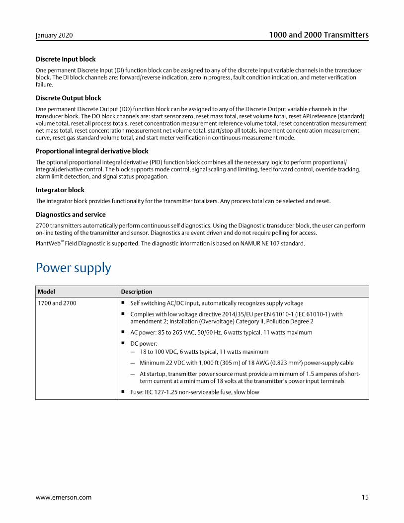
Power supply
Model Description
1700 and 2700 ■ Self switching AC/DC input, automatically recognizes supply voltage
■ Complies with low voltage directive 2014/35/EU per EN 61010-1 (IEC 61010-1) withamendment 2; Installation (Overvoltage) Category II, Pollution Degree 2
■ AC power: 85 to 265 VAC, 50/60 Hz, 6 watts typical, 11 watts maximum
■ DC power:— 18 to 100 VDC, 6 watts typical, 11 watts maximum
— Minimum 22 VDC with 1,000 ft (305 m) of 18 AWG (0.823 mm²) power-supply cable
— At startup, transmitter power source must provide a minimum of 1.5 amperes of short-term current at a minimum of 18 volts at the transmitter’s power input terminals
■ Fuse: IEC 127-1.25 non-serviceable fuse, slow blow
January 2020 1000 and 2000 Transmitters
www.emerson.com 15
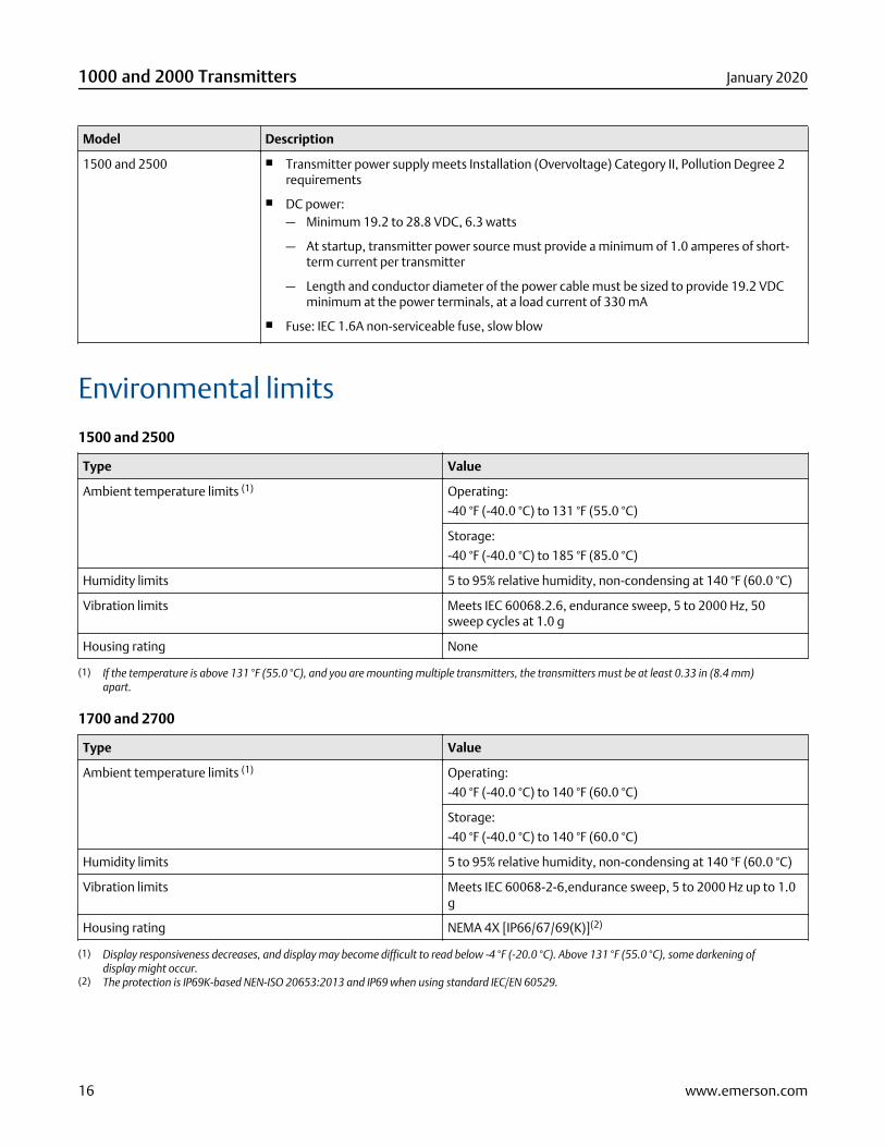
Model Description
1500 and 2500 ■ Transmitter power supply meets Installation (Overvoltage) Category II, Pollution Degree 2requirements
■ DC power:— Minimum 19.2 to 28.8 VDC, 6.3 watts
— At startup, transmitter power source must provide a minimum of 1.0 amperes of short-term current per transmitter
— Length and conductor diameter of the power cable must be sized to provide 19.2 VDCminimum at the power terminals, at a load current of 330 mA
■ Fuse: IEC 1.6A non-serviceable fuse, slow blow
Environmental limits
1500 and 2500
Type Value
Ambient temperature limits (1) Operating:
-40 °F (-40.0 °C) to 131 °F (55.0 °C)
Storage:
-40 °F (-40.0 °C) to 185 °F (85.0 °C)
Humidity limits 5 to 95% relative humidity, non-condensing at 140 °F (60.0 °C)
Vibration limits Meets IEC 60068.2.6, endurance sweep, 5 to 2000 Hz, 50sweep cycles at 1.0 g
Housing rating None
(1) If the temperature is above 131 °F (55.0 °C), and you are mounting multiple transmitters, the transmitters must be at least 0.33 in (8.4 mm)apart.
1700 and 2700
Type Value
Ambient temperature limits (1) Operating:
-40 °F (-40.0 °C) to 140 °F (60.0 °C)
Storage:
-40 °F (-40.0 °C) to 140 °F (60.0 °C)
Humidity limits 5 to 95% relative humidity, non-condensing at 140 °F (60.0 °C)
Vibration limits Meets IEC 60068-2-6,endurance sweep, 5 to 2000 Hz up to 1.0g
Housing rating NEMA 4X [IP66/67/69(K)](2)
(1) Display responsiveness decreases, and display may become difficult to read below -4 °F (-20.0 °C). Above 131 °F (55.0 °C), some darkening ofdisplay might occur.
(2) The protection is IP69K-based NEN-ISO 20653:2013 and IP69 when using standard IEC/EN 60529.
1000 and 2000 Transmitters January 2020
16 www.emerson.com
Environmental effects
EMI effects■ Complies with EMC directive 2014/30/EU per EN 61326 Industrial
■ Complies with NAMUR NE-21 (May 2012). With the exception of voltage dip when powered by 24 VDC on 1700/2700transmitters
Ambient temperature effect■ On analog outputs: ±0.005% of span per °C change from temperature at which the outputs were trimmed
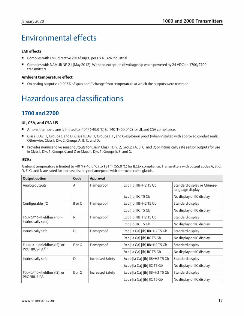
Hazardous area classifications
1700 and 2700
UL, CSA, and CSA-US■ Ambient temperature is limited to -40 °F (-40.0 °C) to 140 °F (60.0 °C) for UL and CSA compliance.
■ Class I, Div. 1, Groups C and D. Class II, Div. 1, Groups E, F, and G explosion proof (when installed with approved conduit seals).Otherwise, Class I, Div. 2, Groups A, B, C, and D.
■ Provides nonincendive sensor outputs for use in Class I, Div. 2, Groups A, B, C, and D; or intrinsically safe sensor outputs for usein Class I, Div. 1, Groups C and D or Class II, Div. 1, Groups E, F, and G.
IECEx
Ambient temperature is limited to -40 °F (-40.0 °C) to 131 °F (55.0 °C) for IECEx compliance. Transmitters with output codes A, B, C,D, E, G, and N are rated for increased safety or flameproof with approved cable glands.
Output option Code Approval
Analog outputs A Flameproof Ex d [ib] IIB+H2 T5 Gb Standard display or Chinese-language display
Ex d [ib] IIC T5 Gb No display or IIC display
Configurable I/O B or C Flameproof Ex d [ib] IIB+H2 T5 Gb Standard display
Ex d [ib] IIC T5 Gb No display or IIC display
FOUNDATION fieldbus (non-intrinsically safe)
N Flameproof Ex d [ib] IIB+H2 T5 Gb Standard display
Ex d [ib] IIC T5 Gb No display or IIC display
Intrinsically safe D Flameproof Ex d [ia Ga] [ib] IIB+H2 T5 Gb Standard display
Ex d [ia Ga] [ib] IIC T5 Gb No display or IIC display
FOUNDATION fieldbus (IS), orPROFIBUS-PA (1)
E or G Flameproof Ex d [ia Ga] [ib] IIB+H2 T5 Gb Standard display
Ex d [ia Ga] [ib] IIC T5 Gb No display or IIC display
Intrinsically safe D Increased Safety Ex de [ia Ga] [ib] IIB+H2 T5 Gb Standard display
Ex de [ia Ga] [ib] IIC T5 Gb No display or IIC display
FOUNDATION fieldbus (IS), orPROFIBUS-PA
E or G Increased Safety Ex de [ia Ga] [ib] IIB+H2 T5 Gb Standard display
Ex de [ia Ga] [ib] IIC T5 Gb No display or IIC display
January 2020 1000 and 2000 Transmitters
www.emerson.com 17
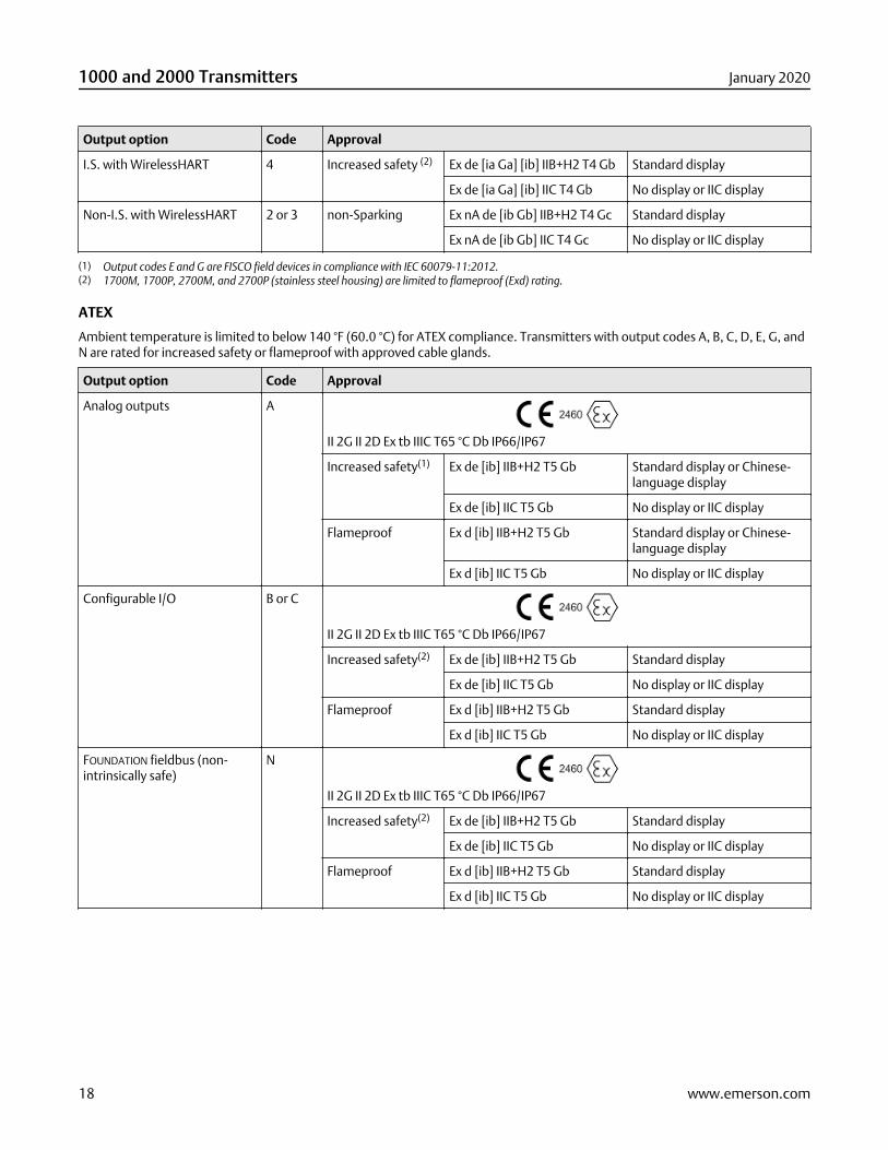
Output option Code Approval
I.S. with WirelessHART 4 Increased safety (2) Ex de [ia Ga] [ib] IIB+H2 T4 Gb Standard display
Ex de [ia Ga] [ib] IIC T4 Gb No display or IIC display
Non-I.S. with WirelessHART 2 or 3 non-Sparking Ex nA de [ib Gb] IIB+H2 T4 Gc Standard display
Ex nA de [ib Gb] IIC T4 Gc No display or IIC display
(1) Output codes E and G are FISCO field devices in compliance with IEC 60079-11:2012.(2) 1700M, 1700P, 2700M, and 2700P (stainless steel housing) are limited to flameproof (Exd) rating.
ATEX
Ambient temperature is limited to below 140 °F (60.0 °C) for ATEX compliance. Transmitters with output codes A, B, C, D, E, G, andN are rated for increased safety or flameproof with approved cable glands.
Output option Code Approval
Analog outputs A
II 2G II 2D Ex tb IIIC T65 °C Db IP66/IP67
Increased safety(1) Ex de [ib] IIB+H2 T5 Gb Standard display or Chinese-language display
Ex de [ib] IIC T5 Gb No display or IIC display
Flameproof Ex d [ib] IIB+H2 T5 Gb Standard display or Chinese-language display
Ex d [ib] IIC T5 Gb No display or IIC display
Configurable I/O B or C
II 2G II 2D Ex tb IIIC T65 °C Db IP66/IP67
Increased safety(2) Ex de [ib] IIB+H2 T5 Gb Standard display
Ex de [ib] IIC T5 Gb No display or IIC display
Flameproof Ex d [ib] IIB+H2 T5 Gb Standard display
Ex d [ib] IIC T5 Gb No display or IIC display
FOUNDATION fieldbus (non-intrinsically safe)
N
II 2G II 2D Ex tb IIIC T65 °C Db IP66/IP67
Increased safety(2) Ex de [ib] IIB+H2 T5 Gb Standard display
Ex de [ib] IIC T5 Gb No display or IIC display
Flameproof Ex d [ib] IIB+H2 T5 Gb Standard display
Ex d [ib] IIC T5 Gb No display or IIC display
1000 and 2000 Transmitters January 2020
18 www.emerson.com
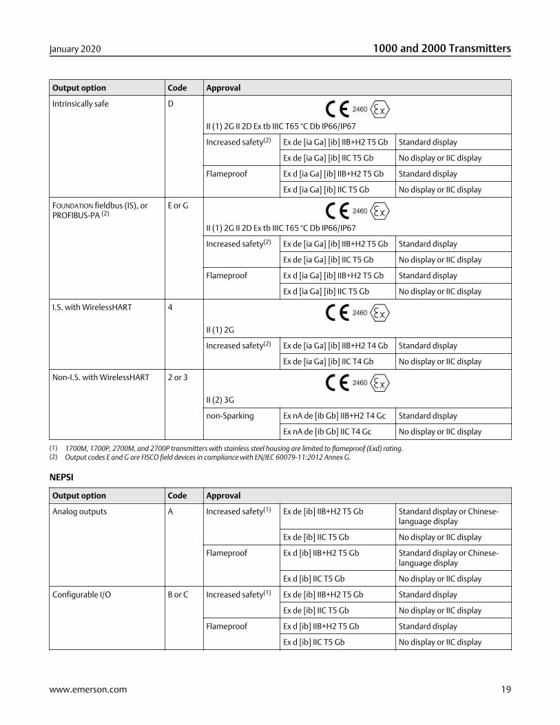
Output option Code Approval
Intrinsically safe D
II (1) 2G II 2D Ex tb IIIC T65 °C Db IP66/IP67
Increased safety(2) Ex de [ia Ga] [ib] IIB+H2 T5 Gb Standard display
Ex de [ia Ga] [ib] IIC T5 Gb No display or IIC display
Flameproof Ex d [ia Ga] [ib] IIB+H2 T5 Gb Standard display
Ex d [ia Ga] [ib] IIC T5 Gb No display or IIC display
FOUNDATION fieldbus (IS), orPROFIBUS-PA (2)
E or G
II (1) 2G II 2D Ex tb IIIC T65 °C Db IP66/IP67
Increased safety(2) Ex de [ia Ga] [ib] IIB+H2 T5 Gb Standard display
Ex de [ia Ga] [ib] IIC T5 Gb No display or IIC display
Flameproof Ex d [ia Ga] [ib] IIB+H2 T5 Gb Standard display
Ex d [ia Ga] [ib] IIC T5 Gb No display or IIC display
I.S. with WirelessHART 4
II (1) 2G
Increased safety(2) Ex de [ia Ga] [ib] IIB+H2 T4 Gb Standard display
Ex de [ia Ga] [ib] IIC T4 Gb No display or IIC display
Non-I.S. with WirelessHART 2 or 3
II (2) 3G
non-Sparking Ex nA de [ib Gb] IIB+H2 T4 Gc Standard display
Ex nA de [ib Gb] IIC T4 Gc No display or IIC display
(1) 1700M, 1700P, 2700M, and 2700P transmitters with stainless steel housing are limited to flameproof (Exd) rating.(2) Output codes E and G are FISCO field devices in compliance with EN/IEC 60079-11:2012 Annex G.
NEPSI
Output option Code Approval
Analog outputs A Increased safety(1) Ex de [ib] IIB+H2 T5 Gb Standard display or Chinese-language display
Ex de [ib] IIC T5 Gb No display or IIC display
Flameproof Ex d [ib] IIB+H2 T5 Gb Standard display or Chinese-language display
Ex d [ib] IIC T5 Gb No display or IIC display
Configurable I/O B or C Increased safety(1) Ex de [ib] IIB+H2 T5 Gb Standard display
Ex de [ib] IIC T5 Gb No display or IIC display
Flameproof Ex d [ib] IIB+H2 T5 Gb Standard display
Ex d [ib] IIC T5 Gb No display or IIC display
January 2020 1000 and 2000 Transmitters
www.emerson.com 19
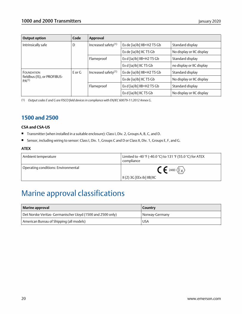
Output option Code Approval
Intrinsically safe D Increased safety(1) Ex de [ia/ib] IIB+H2 T5 Gb Standard display
Ex de [ia/ib] IIC T5 Gb No display or IIC display
Flameproof Ex d [ia/ib] IIB+H2 T5 Gb Standard display
Ex d [ia/ib] IIC T5 Gb no display or IIC display
FOUNDATION
fieldbus (IS), or PROFIBUS-PA(1)
E or G Increased safety(1) Ex de [ia/ib] IIB+H2 T5 Gb Standard display
Ex de [ia/ib] IIC T5 Gb No display or IIC display
Flameproof Ex d [ia/ib] IIB+H2 T5 Gb Standard display
Ex d [ia/ib] IIC T5 Gb No display or IIC display
(1) Output codes E and G are FISCO field devices in compliance with EN/IEC 60079-11:2012 Annex G.
1500 and 2500
CSA and CSA-US■ Transmitter (when installed in a suitable enclosure): Class I, Div. 2, Groups A, B, C, and D.
■ Sensor, including wiring to sensor: Class I, Div. 1, Groups C and D or Class II, Div. 1, Groups E, F, and G.
ATEX
Ambient temperature Limited to -40 °F (-40.0 °C) to 131 °F (55.0 °C) for ATEXcompliance
Operating conditions: Environmental
II (2) 3G [EEx ib] IIB/IIC
Marine approval classifications
Marine approval Country
Det Norske Veritas- Germanischer Lloyd (1500 and 2500 only) Norway-Germany
American Bureau of Shipping (all models) USA
1000 and 2000 Transmitters January 2020
20 www.emerson.com
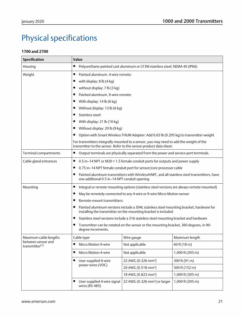
Physical specifications
1700 and 2700
Specification Value
Housing ■ Polyurethane-painted cast aluminum or CF3M stainless steel; NEMA 4X (IP66)
Weight ■ Painted aluminum, 4-wire remote:
■ with display: 8 lb (4 kg)
■ without display: 7 lb (3 kg)
■ Painted aluminum, 9-wire remote:
■ With display: 14 lb (6 kg)
■ Without display: 13 lb (6 kg)
■ Stainless steel:
■ With display: 21 lb (10 kg)
■ Without display: 20 lb (9 kg)
■ Option with Smart Wireless THUM Adapter: Add 0.65 lb (0.295 kg) to transmitter weight
For transmitters integrally mounted to a sensor, you may need to add the weight of thetransmitter to the sensor. Refer to the sensor product data sheet.
Terminal compartments ■ Output terminals are physically separated from the power and service-port terminals.
Cable gland entrances ■ 0.5 in–14 NPT or M20 × 1.5 female conduit ports for outputs and power supply
■ 0.75 in–14 NPT female conduit port for sensor/core processor cable
■ Painted aluminum transmitters with WirelessHART, and all stainless steel transmitters, haveone additional 0.5 in–14 NPT conduit opening
Mounting ■ Integral or remote mounting options (stainless steel versions are always remote mounted)
■ May be remotely connected to any 4-wire or 9-wire Micro Motion sensor
■ Remote-mount transmitters:
■ Painted aluminum versions include a 304L stainless steel mounting bracket; hardware forinstalling the transmitter on the mounting bracket is included
■ Stainless steel versions include a 316 stainless steel mounting bracket and hardware
■ Transmitter can be rotated on the sensor or the mounting bracket, 360 degrees, in 90-degree increments.
Maximum cable lengthsbetween sensor andtransmitter(1)
Cable type Wire gauge Maximum length
■ Micro Motion 9-wire Not applicable 60 ft (18 m)
■ Micro Motion 4-wire Not applicable 1,000 ft (305 m)
■ User-supplied 4-wirepower wires (VDC)
22 AWG (0.326 mm²) 300 ft (91 m)
20 AWG (0.518 mm²) 500 ft (152 m)
18 AWG (0.823 mm²) 1,000 ft (305 m)
■ User-supplied 4-wire signalwires (RS-485)
22 AWG (0.326 mm²) or larger 1,000 ft (305 m)
January 2020 1000 and 2000 Transmitters
www.emerson.com 21
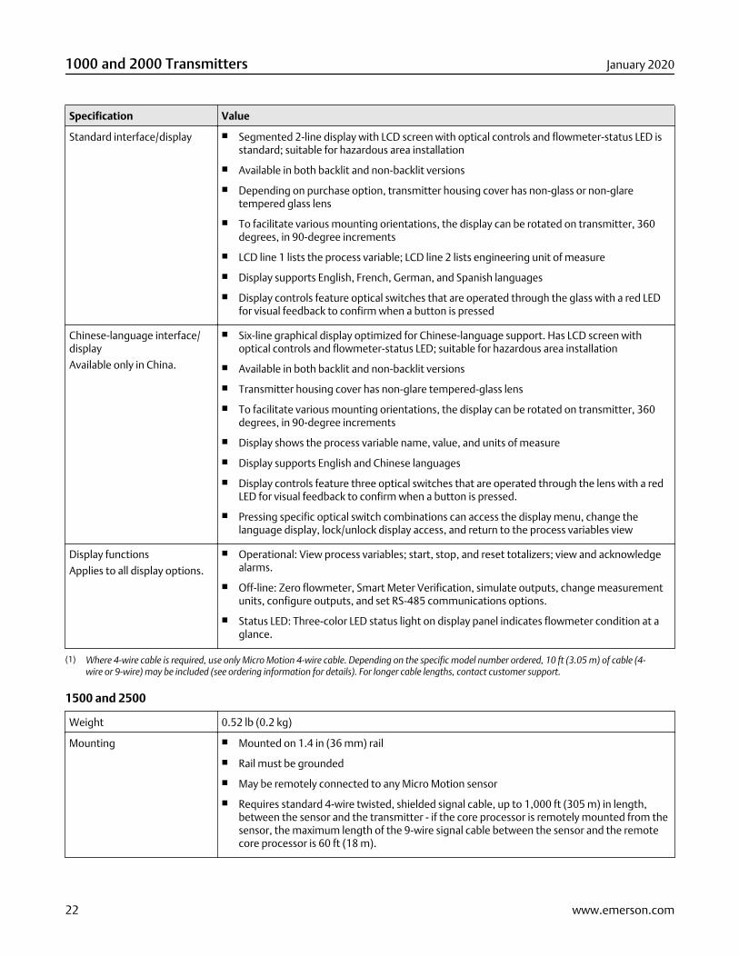
Specification Value
Standard interface/display ■ Segmented 2-line display with LCD screen with optical controls and flowmeter-status LED isstandard; suitable for hazardous area installation
■ Available in both backlit and non-backlit versions
■ Depending on purchase option, transmitter housing cover has non-glass or non-glaretempered glass lens
■ To facilitate various mounting orientations, the display can be rotated on transmitter, 360degrees, in 90-degree increments
■ LCD line 1 lists the process variable; LCD line 2 lists engineering unit of measure
■ Display supports English, French, German, and Spanish languages
■ Display controls feature optical switches that are operated through the glass with a red LEDfor visual feedback to confirm when a button is pressed
Chinese-language interface/display
Available only in China.
■ Six-line graphical display optimized for Chinese-language support. Has LCD screen withoptical controls and flowmeter-status LED; suitable for hazardous area installation
■ Available in both backlit and non-backlit versions
■ Transmitter housing cover has non-glare tempered-glass lens
■ To facilitate various mounting orientations, the display can be rotated on transmitter, 360degrees, in 90-degree increments
■ Display shows the process variable name, value, and units of measure
■ Display supports English and Chinese languages
■ Display controls feature three optical switches that are operated through the lens with a redLED for visual feedback to confirm when a button is pressed.
■ Pressing specific optical switch combinations can access the display menu, change thelanguage display, lock/unlock display access, and return to the process variables view
Display functions
Applies to all display options.
■ Operational: View process variables; start, stop, and reset totalizers; view and acknowledgealarms.
■ Off-line: Zero flowmeter, Smart Meter Verification, simulate outputs, change measurementunits, configure outputs, and set RS-485 communications options.
■ Status LED: Three-color LED status light on display panel indicates flowmeter condition at aglance.
(1) Where 4-wire cable is required, use only Micro Motion 4-wire cable. Depending on the specific model number ordered, 10 ft (3.05 m) of cable (4-wire or 9-wire) may be included (see ordering information for details). For longer cable lengths, contact customer support.
1500 and 2500
Weight 0.52 lb (0.2 kg)
Mounting ■ Mounted on 1.4 in (36 mm) rail
■ Rail must be grounded
■ May be remotely connected to any Micro Motion sensor
■ Requires standard 4-wire twisted, shielded signal cable, up to 1,000 ft (305 m) in length,between the sensor and the transmitter - if the core processor is remotely mounted from thesensor, the maximum length of the 9-wire signal cable between the sensor and the remotecore processor is 60 ft (18 m).
1000 and 2000 Transmitters January 2020
22 www.emerson.com
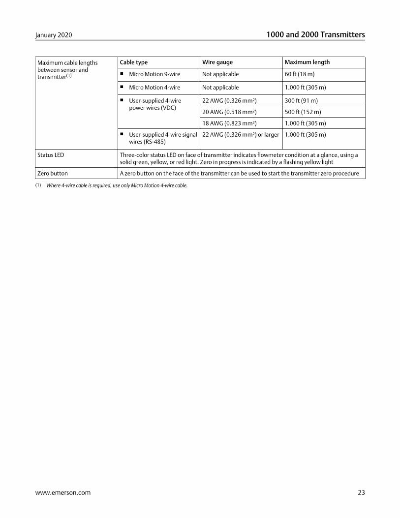
Maximum cable lengthsbetween sensor andtransmitter(1)
Cable type Wire gauge Maximum length
■ Micro Motion 9-wire Not applicable 60 ft (18 m)
■ Micro Motion 4-wire Not applicable 1,000 ft (305 m)
■ User-supplied 4-wirepower wires (VDC)
22 AWG (0.326 mm²) 300 ft (91 m)
20 AWG (0.518 mm²) 500 ft (152 m)
18 AWG (0.823 mm²) 1,000 ft (305 m)
■ User-supplied 4-wire signalwires (RS-485)
22 AWG (0.326 mm²) or larger 1,000 ft (305 m)
Status LED Three-color status LED on face of transmitter indicates flowmeter condition at a glance, using asolid green, yellow, or red light. Zero in progress is indicated by a flashing yellow light
Zero button A zero button on the face of the transmitter can be used to start the transmitter zero procedure
(1) Where 4-wire cable is required, use only Micro Motion 4-wire cable.
January 2020 1000 and 2000 Transmitters
www.emerson.com 23
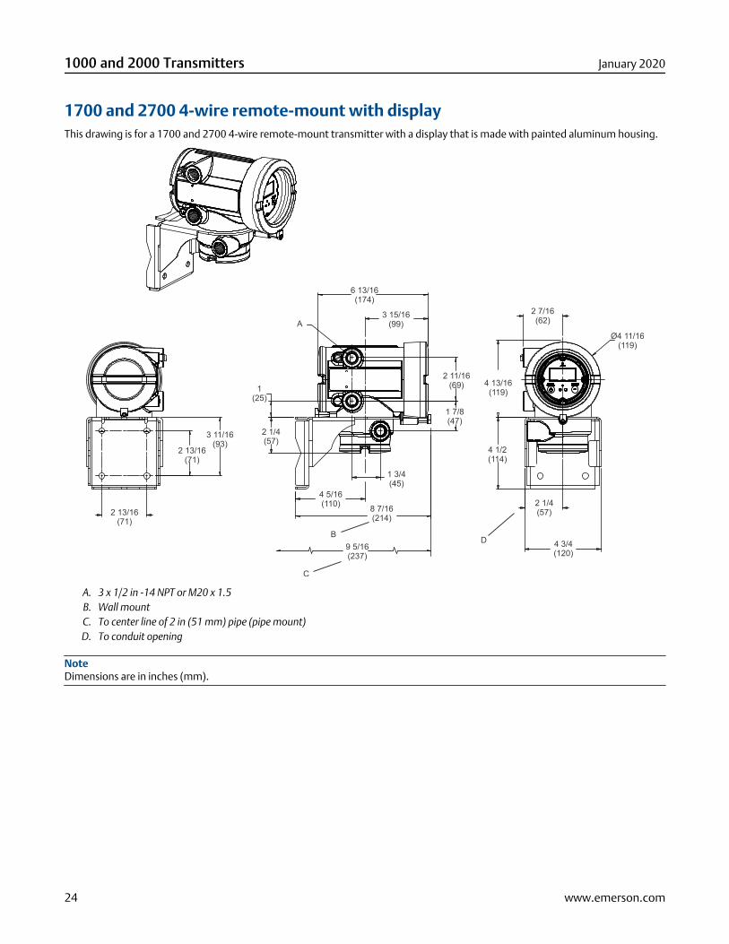
1700 and 2700 4-wire remote-mount with displayThis drawing is for a 1700 and 2700 4-wire remote-mount transmitter with a display that is made with painted aluminum housing.
6 13/16(174)
3 15/16(99)
2 7/16(62)
Ø4 11/16(119)
4 13/16(119)
4 1/2(114)
2 11/16(69)
1 7/8(47)
A
BD
2 1/4(57)
9 5/16(237)
C
8 7/16(214)
4 5/16(110)
1 3/4(45)
1(25)
2 1/4(57)
3 11/16(93)
2 13/16(71)
2 13/16(71)
4 3/4(120)
A. 3 x 1/2 in -14 NPT or M20 x 1.5B. Wall mountC. To center line of 2 in (51 mm) pipe (pipe mount)D. To conduit opening
NoteDimensions are in inches (mm).
1000 and 2000 Transmitters January 2020
24 www.emerson.com
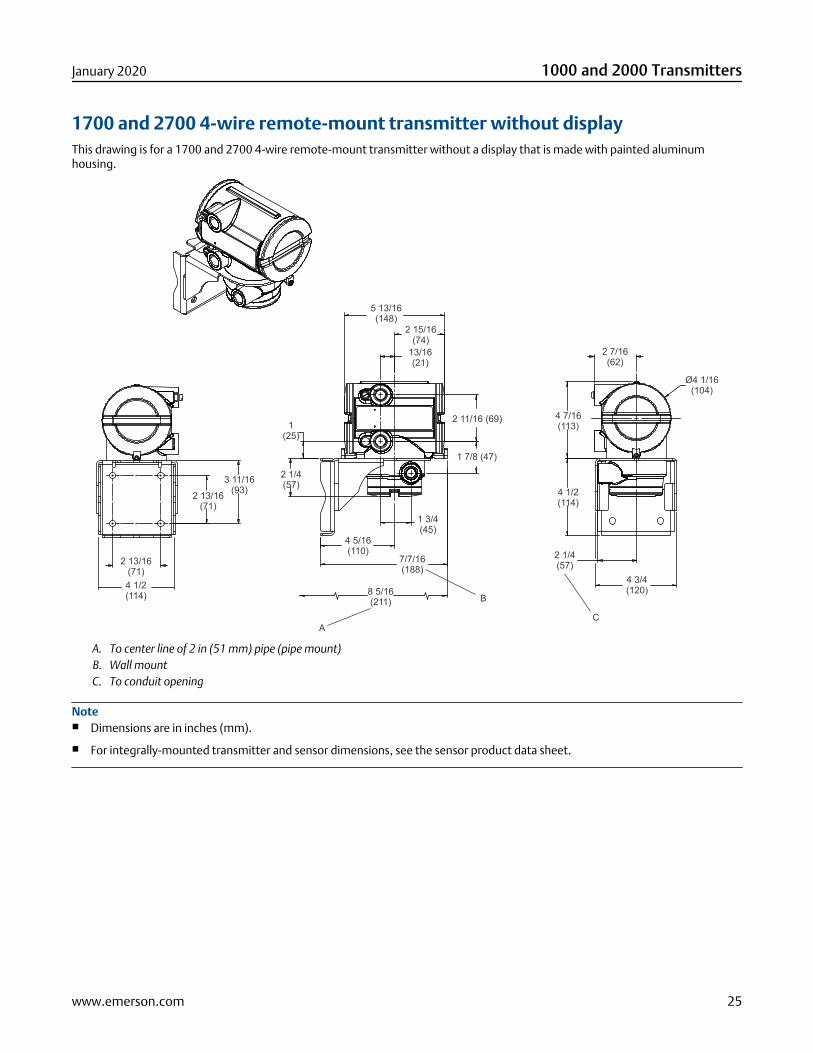
1700 and 2700 4-wire remote-mount transmitter without displayThis drawing is for a 1700 and 2700 4-wire remote-mount transmitter without a display that is made with painted aluminumhousing.
3 11/16(93)2 13/16
(71)
2 13/16(71)4 1/2(114)
5 13/16(148)
2 15/16(74)
13/16(21)
2 11/16 (69)
1 7/8 (47)
1(25)
2 1/4(57)
4 5/16(110)
7/7/16(188)
8 5/16(211)
A
B
2 7/16(62)
Ø4 1/16(104)
4 7/16(113)
4 1/2(114)
2 1/4(57)
4 3/4(120)
C
1 3/4(45)
A. To center line of 2 in (51 mm) pipe (pipe mount)B. Wall mountC. To conduit opening
Note■ Dimensions are in inches (mm).
■ For integrally-mounted transmitter and sensor dimensions, see the sensor product data sheet.
January 2020 1000 and 2000 Transmitters
www.emerson.com 25
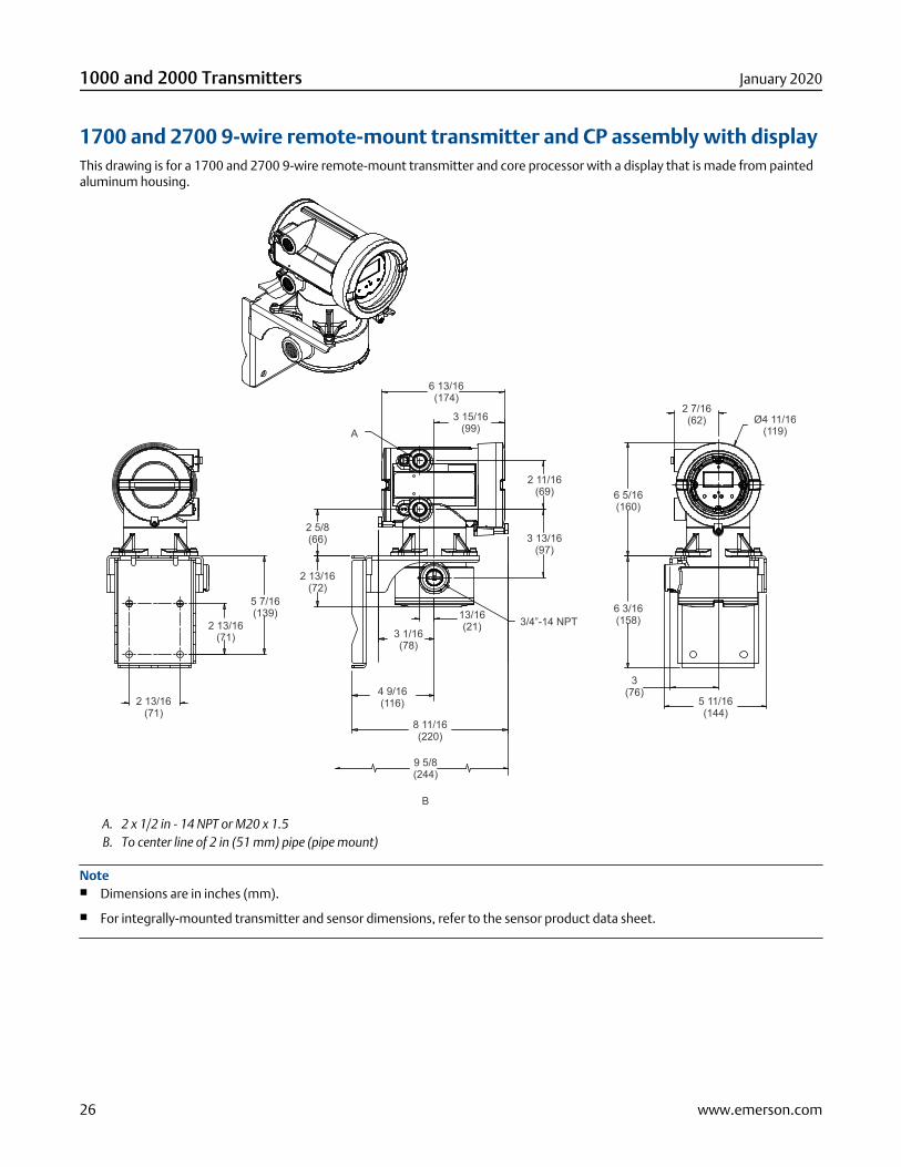
1700 and 2700 9-wire remote-mount transmitter and CP assembly with displayThis drawing is for a 1700 and 2700 9-wire remote-mount transmitter and core processor with a display that is made from paintedaluminum housing.
A
B
9 5/8(244)
5 7/16(139)
2 13/16(71)
2 13/16(71)
6 13/16(174)
3 15/16(99)
2 11/16(69)
3 13/16(97)
2 5/8(66)
2 13/16(72)
3/4”-14 NPT13/16(21)
3 1/16(78)
4 9/16(116)
8 11/16(220)
2 7/16(62) Ø4 11/16
(119)
6 5/16(160)
6 3/16(158)
3(76)
5 11/16(144)
A. 2 x 1/2 in - 14 NPT or M20 x 1.5B. To center line of 2 in (51 mm) pipe (pipe mount)
Note■ Dimensions are in inches (mm).
■ For integrally-mounted transmitter and sensor dimensions, refer to the sensor product data sheet.
1000 and 2000 Transmitters January 2020
26 www.emerson.com
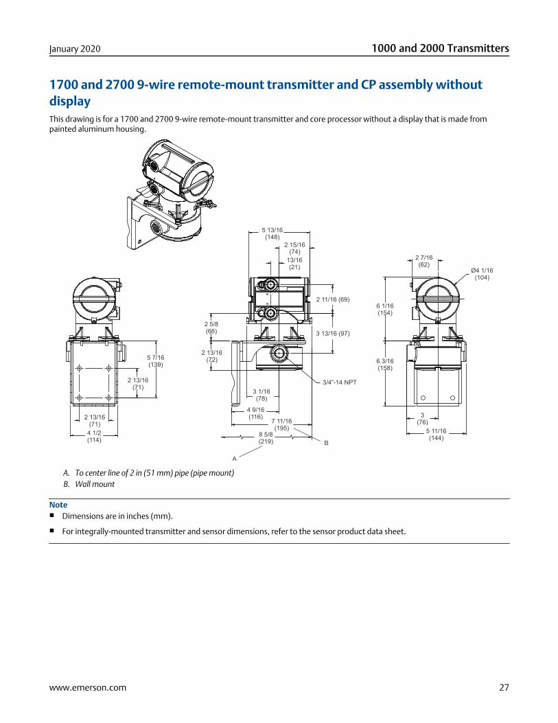
1700 and 2700 9-wire remote-mount transmitter and CP assembly withoutdisplayThis drawing is for a 1700 and 2700 9-wire remote-mount transmitter and core processor without a display that is made frompainted aluminum housing.
5 7/16(139)
2 13/16(71)
2 13/16(71)
4 1/2(114)
5 13/16(148)
2 15/16(74)
13/16(21)
2 11/16 (69)
3 13/16 (97)
2 13/16(72)
4 9/16(116)
2 5/8(66)
3 1/16(78)
7 11/16(195)
8 5/8(219)
3/4”-14 NPT
B
A
2 7/16(62)
Ø4 1/16(104)
6 1/16(154)
6 3/16(158)
3(76)
5 11/16(144)
A. To center line of 2 in (51 mm) pipe (pipe mount)B. Wall mount
Note■ Dimensions are in inches (mm).
■ For integrally-mounted transmitter and sensor dimensions, refer to the sensor product data sheet.
January 2020 1000 and 2000 Transmitters
www.emerson.com 27
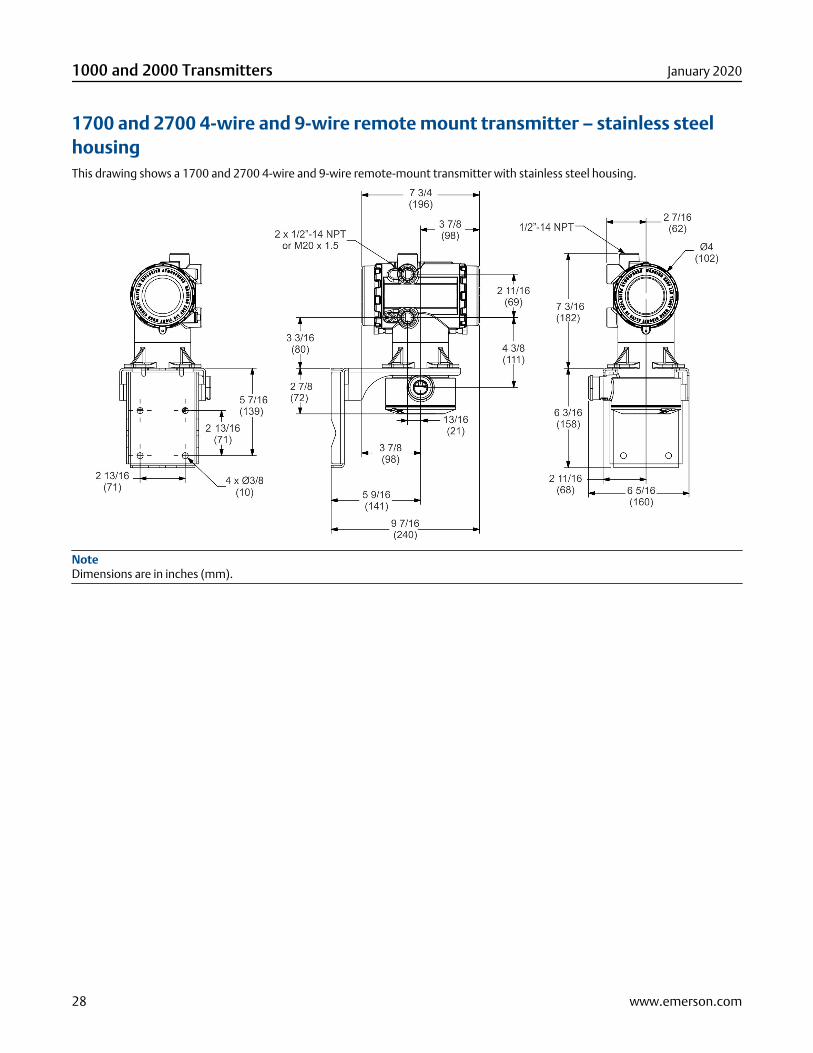
1700 and 2700 4-wire and 9-wire remote mount transmitter – stainless steelhousingThis drawing shows a 1700 and 2700 4-wire and 9-wire remote-mount transmitter with stainless steel housing.
NoteDimensions are in inches (mm).
1000 and 2000 Transmitters January 2020
28 www.emerson.com
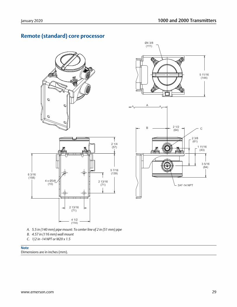
Remote (standard) core processorØ4 3/8(111)
5 11/16(144)
A
B C2 1/2(64)
2 3/8(61)
1 11/16(43)
3/4”-14 NPT
3 5/16(84)
2 1/4(57)
5 7/16(139)
2 13/16(71)
2 13/16(71)
4 1/2(114)
4 x Ø3/8(10)
6 3/16(158)
A. 5.5 in (140 mm) pipe mount: To center line of 2 in (51 mm) pipeB. 4.57 in (116 mm) wall mountC. 1/2 in -14 NPT or M20 x 1.5
NoteDimensions are in inches (mm).
January 2020 1000 and 2000 Transmitters
www.emerson.com 29
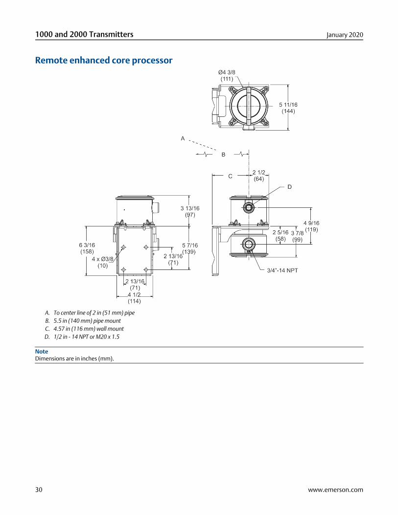
Remote enhanced core processor
A. To center line of 2 in (51 mm) pipeB. 5.5 in (140 mm) pipe mountC. 4.57 in (116 mm) wall mountD. 1/2 in - 14 NPT or M20 x 1.5
NoteDimensions are in inches (mm).
1000 and 2000 Transmitters January 2020
30 www.emerson.com
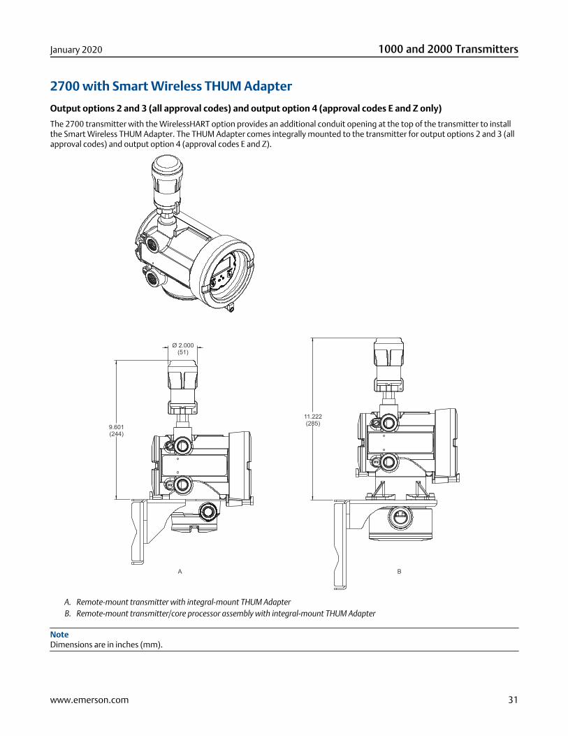
2700 with Smart Wireless THUM Adapter
Output options 2 and 3 (all approval codes) and output option 4 (approval codes E and Z only)
The 2700 transmitter with the WirelessHART option provides an additional conduit opening at the top of the transmitter to installthe Smart Wireless THUM Adapter. The THUM Adapter comes integrally mounted to the transmitter for output options 2 and 3 (allapproval codes) and output option 4 (approval codes E and Z).
Ø 2.000(51)
9.601(244)
11.222(285)
A B
A. Remote-mount transmitter with integral-mount THUM AdapterB. Remote-mount transmitter/core processor assembly with integral-mount THUM Adapter
NoteDimensions are in inches (mm).
January 2020 1000 and 2000 Transmitters
www.emerson.com 31
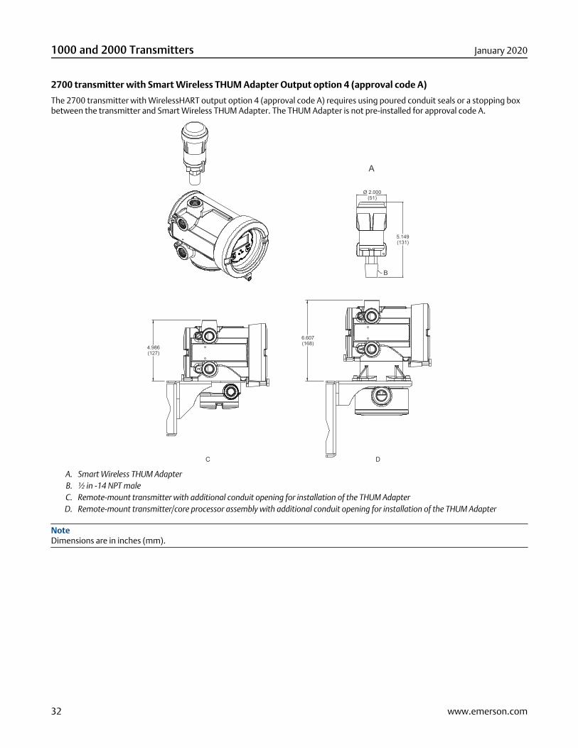
2700 transmitter with Smart Wireless THUM Adapter Output option 4 (approval code A)
The 2700 transmitter with WirelessHART output option 4 (approval code A) requires using poured conduit seals or a stopping boxbetween the transmitter and Smart Wireless THUM Adapter. The THUM Adapter is not pre-installed for approval code A.
A
C D
Ø 2.000(51)
5.149(131)
B
6.607(168)
4.986(127)
A. Smart Wireless THUM AdapterB. ½ in -14 NPT maleC. Remote-mount transmitter with additional conduit opening for installation of the THUM AdapterD. Remote-mount transmitter/core processor assembly with additional conduit opening for installation of the THUM Adapter
NoteDimensions are in inches (mm).
1000 and 2000 Transmitters January 2020
32 www.emerson.com
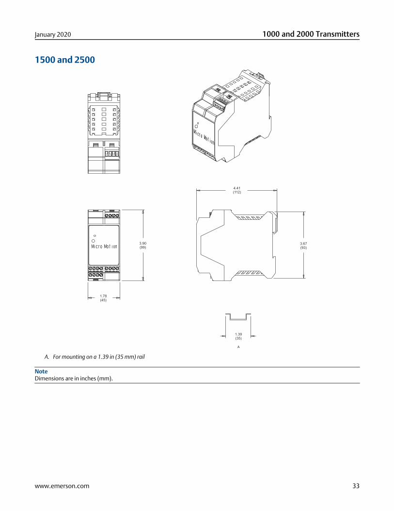
1500 and 2500
4.41(112)
3.67(93)
3.90(99)
1.78(45)
1.39(35)
A
A. For mounting on a 1.39 in (35 mm) rail
NoteDimensions are in inches (mm).
January 2020 1000 and 2000 Transmitters
www.emerson.com 33
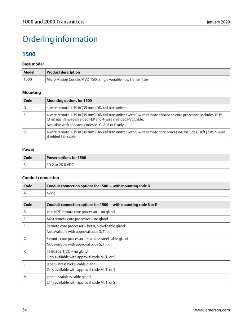
Ordering information
1500
Base model
Model Product description
1500 Micro Motion Coriolis MVD 1500 single variable flow transmitter
Mounting
Code Mounting options for 1500
D 4-wire remote 1.39 in (35 mm) DIN rail transmitter
E 4-wire remote 1.39 in (35 mm) DIN rail transmitter with 9-wire remote enhanced core processor; includes 10 ft(3 m) each 9-wire shielded FEP and 4-wire shielded PVC cable;
Available with approval codes M, C, A, B or P only
B 4-wire remote 1.39 in (35 mm) DIN rail transmitter with 9-wire remote core processor; includes 10 ft (3 m) 9-wireshielded FEP cable
Power
Code Power options for 1500
3 19.2 to 28.8 VDC
Conduit connection
Code Conduit connection options for 1500 — with mounting code D
A None
Code Conduit connection options for 1500 — with mounting code B or E
B ½ in NPT remote core processor – no gland
E M20 remote core processor – no gland
F Remote core processor – brass/nickel cable gland
Not available with approval code S, T, or J
G Remote core processor – stainless steel cable gland
Not available with approval code S, T, or J
K JIS B0202 1/2G – no gland
Only available with approval code M, T, or S
L Japan - brass nickel cable gland
Only available with approval code M, T, or S
M Japan - stainless cable gland
Only available with approval code M, T, or S
1000 and 2000 Transmitters January 2020
34 www.emerson.com
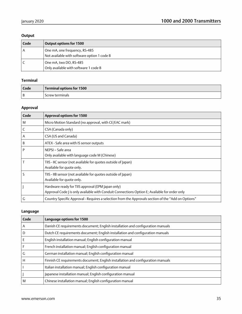
Output
Code Output options for 1500
A One mA, one frequency, RS-485
Not available with software option 1 code B
C One mA, two DO, RS-485
Only available with software 1 code B
Terminal
Code Terminal options for 1500
B Screw terminals
Approval
Code Approval options for 1500
M Micro Motion Standard (no approval, with CE/EAC mark)
C CSA (Canada only)
A CSA (US and Canada)
B ATEX - Safe area with IS sensor outputs
P NEPSI – Safe area
Only available with language code M (Chinese)
T TIIS - IIC sensor (not available for quotes outside of Japan)
Available for quote only.
S TIIS - IIB sensor (not available for quotes outside of Japan)
Available for quote only.
J Hardware ready for TIIS approval (EPM Japan only)
Approval Code J is only available with Conduit Connections Option E; Available for order only
G Country Specific Approval - Requires a selection from the Approvals section of the “Add on Options”
Language
Code Language options for 1500
A Danish CE requirements document; English installation and configuration manuals
D Dutch CE requirements document; English installation and configuration manuals
E English installation manual; English configuration manual
F French installation manual; English configuration manual
G German installation manual; English configuration manual
H Finnish CE requirements document; English installation and configuration manuals
I Italian installation manual; English configuration manual
J Japanese installation manual; English configuration manual
M Chinese installation manual; English configuration manual
January 2020 1000 and 2000 Transmitters
www.emerson.com 35
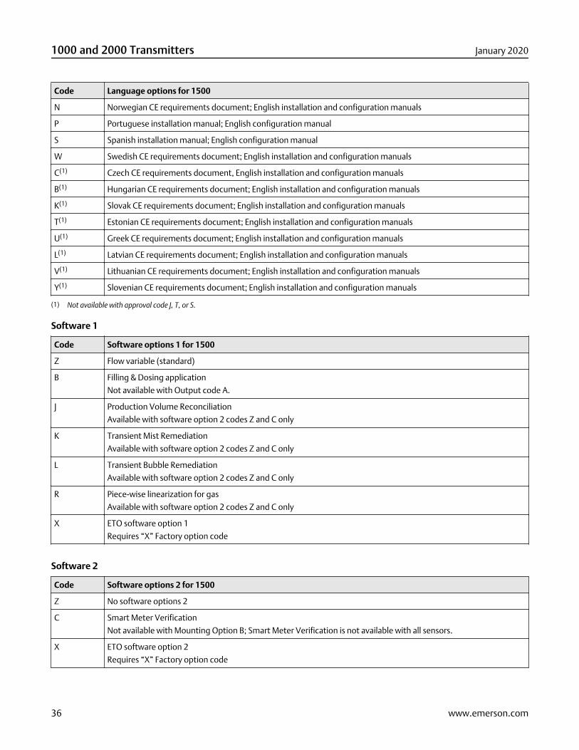
Code Language options for 1500
N Norwegian CE requirements document; English installation and configuration manuals
P Portuguese installation manual; English configuration manual
S Spanish installation manual; English configuration manual
W Swedish CE requirements document; English installation and configuration manuals
C(1) Czech CE requirements document, English installation and configuration manuals
B(1) Hungarian CE requirements document; English installation and configuration manuals
K(1) Slovak CE requirements document; English installation and configuration manuals
T(1) Estonian CE requirements document; English installation and configuration manuals
U(1) Greek CE requirements document; English installation and configuration manuals
L(1) Latvian CE requirements document; English installation and configuration manuals
V(1) Lithuanian CE requirements document; English installation and configuration manuals
Y(1) Slovenian CE requirements document; English installation and configuration manuals
(1) Not available with approval code J, T, or S.
Software 1
Code Software options 1 for 1500
Z Flow variable (standard)
B Filling & Dosing application
Not available with Output code A.
J Production Volume Reconciliation
Available with software option 2 codes Z and C only
K Transient Mist Remediation
Available with software option 2 codes Z and C only
L Transient Bubble Remediation
Available with software option 2 codes Z and C only
R Piece-wise linearization for gas
Available with software option 2 codes Z and C only
X ETO software option 1
Requires “X” Factory option code
Software 2
Code Software options 2 for 1500
Z No software options 2
C Smart Meter Verification
Not available with Mounting Option B; Smart Meter Verification is not available with all sensors.
X ETO software option 2
Requires “X” Factory option code
1000 and 2000 Transmitters January 2020
36 www.emerson.com
Factory
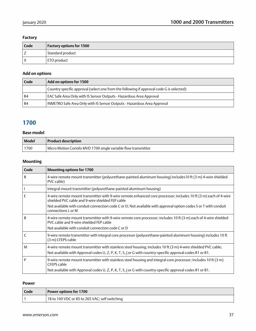
Code Factory options for 1500
Z Standard product
X ETO product
Add on options
Code Add on options for 1500
Country specific approval (select one from the following if approval code G is selected):
R4 EAC Safe Area Only with IS Sensor Outputs - Hazardous Area Approval
B4 INMETRO Safe Area Only with IS Sensor Outputs - Hazardous Area Approval
1700
Base model
Model Product description
1700 Micro Motion Coriolis MVD 1700 single variable flow transmitter
Mounting
Code Mounting options for 1700
R 4-wire remote mount transmitter (polyurethane-painted aluminum housing) includes10 ft (3 m) 4-wire shieldedPVC cable)
I Integral mount transmitter (polyurethane-painted aluminum housing)
E 4-wire remote mount transmitter with 9-wire remote enhanced core processor; includes 10 ft (3 m) each of 4-wireshielded PVC cable and 9-wire shielded FEP cable
Not available with conduit connection code C or D; Not available with approval option codes S or T with conduitconnections L or M
B 4-wire remote mount transmitter with 9-wire remote core processor; includes 10 ft (3 m) each of 4-wire shieldedPVC cable and 9-wire shielded FEP cable
Not available with conduit connection code C or D
C 9-wire remote transmitter with integral core processor (polyurethane-painted aluminum housing) includes 10 ft(3 m) CFEPS cable
M 4-wire remote mount transmitter with stainless steel housing; includes 10 ft (3 m) 4-wire shielded PVC cable;
Not available with Approval codes U, Z, P, K, T, S, J or G with country-specific approval codes R1 or B1.
P 9-wire remote mount transmitter with stainless steel housing and integral core processor; includes 10 ft (3 m)CFEPS cable
Not available with Approval codes U, Z, P, K, T, S, J or G with country-specific approval codes R1 or B1.
Power
Code Power options for 1700
1 18 to 100 VDC or 85 to 265 VAC; self switching
January 2020 1000 and 2000 Transmitters
www.emerson.com 37
Display
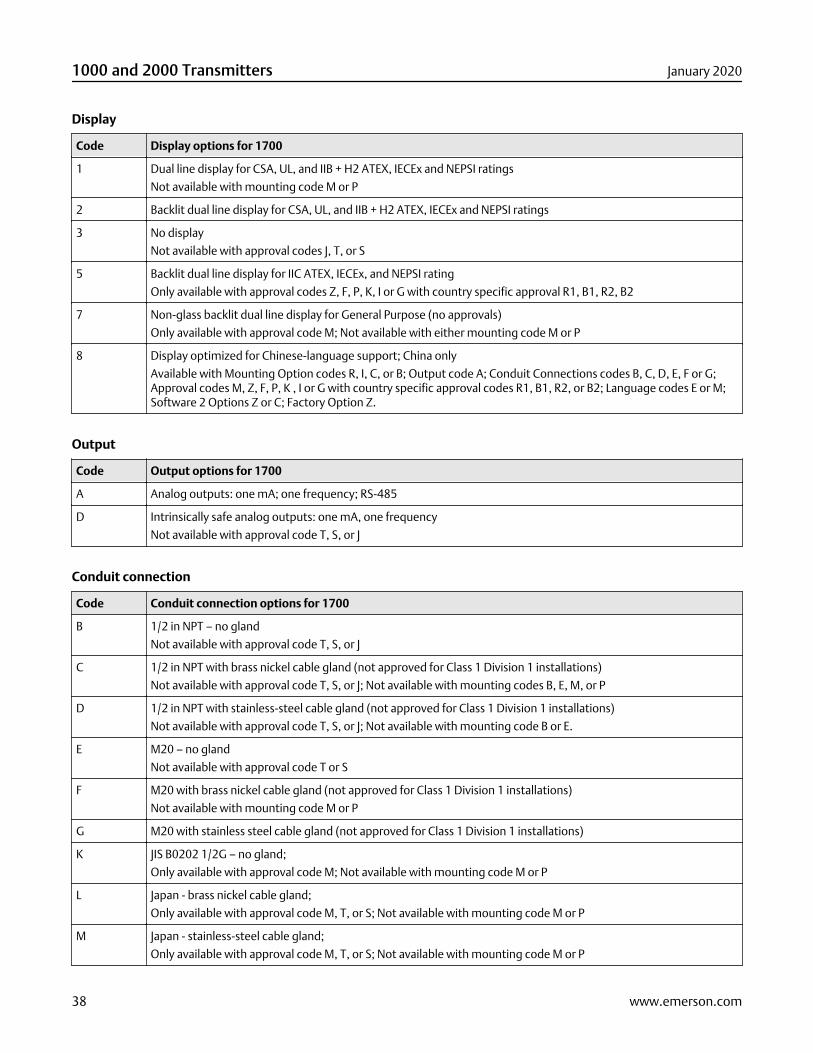
Code Display options for 1700
1 Dual line display for CSA, UL, and IIB + H2 ATEX, IECEx and NEPSI ratings
Not available with mounting code M or P
2 Backlit dual line display for CSA, UL, and IIB + H2 ATEX, IECEx and NEPSI ratings
3 No display
Not available with approval codes J, T, or S
5 Backlit dual line display for IIC ATEX, IECEx, and NEPSI rating
Only available with approval codes Z, F, P, K, I or G with country specific approval R1, B1, R2, B2
7 Non-glass backlit dual line display for General Purpose (no approvals)
Only available with approval code M; Not available with either mounting code M or P
8 Display optimized for Chinese-language support; China only
Available with Mounting Option codes R, I, C, or B; Output code A; Conduit Connections codes B, C, D, E, F or G;Approval codes M, Z, F, P, K , I or G with country specific approval codes R1, B1, R2, or B2; Language codes E or M;Software 2 Options Z or C; Factory Option Z.
Output
Code Output options for 1700
A Analog outputs: one mA; one frequency; RS-485
D Intrinsically safe analog outputs: one mA, one frequency
Not available with approval code T, S, or J
Conduit connection
Code Conduit connection options for 1700
B 1/2 in NPT – no gland
Not available with approval code T, S, or J
C 1/2 in NPT with brass nickel cable gland (not approved for Class 1 Division 1 installations)
Not available with approval code T, S, or J; Not available with mounting codes B, E, M, or P
D 1/2 in NPT with stainless-steel cable gland (not approved for Class 1 Division 1 installations)
Not available with approval code T, S, or J; Not available with mounting code B or E.
E M20 – no gland
Not available with approval code T or S
F M20 with brass nickel cable gland (not approved for Class 1 Division 1 installations)
Not available with mounting code M or P
G M20 with stainless steel cable gland (not approved for Class 1 Division 1 installations)
K JIS B0202 1/2G – no gland;
Only available with approval code M; Not available with mounting code M or P
L Japan - brass nickel cable gland;
Only available with approval code M, T, or S; Not available with mounting code M or P
M Japan - stainless-steel cable gland;
Only available with approval code M, T, or S; Not available with mounting code M or P
1000 and 2000 Transmitters January 2020
38 www.emerson.com
Approval
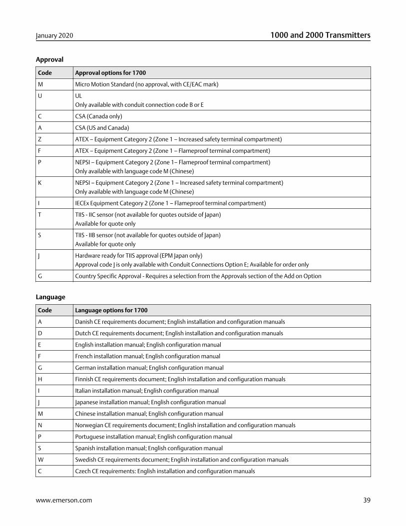
Code Approval options for 1700
M Micro Motion Standard (no approval, with CE/EAC mark)
U UL
Only available with conduit connection code B or E
C CSA (Canada only)
A CSA (US and Canada)
Z ATEX – Equipment Category 2 (Zone 1 – Increased safety terminal compartment)
F ATEX – Equipment Category 2 (Zone 1 – Flameproof terminal compartment)
P NEPSI – Equipment Category 2 (Zone 1– Flameproof terminal compartment)
Only available with language code M (Chinese)
K NEPSI – Equipment Category 2 (Zone 1 – Increased safety terminal compartment)
Only available with language code M (Chinese)
I IECEx Equipment Category 2 (Zone 1 – Flameproof terminal compartment)
T TIIS - IIC sensor (not available for quotes outside of Japan)
Available for quote only
S TIIS - IIB sensor (not available for quotes outside of Japan)
Available for quote only
J Hardware ready for TIIS approval (EPM Japan only)
Approval code J is only available with Conduit Connections Option E; Available for order only
G Country Specific Approval - Requires a selection from the Approvals section of the Add on Option
Language
Code Language options for 1700
A Danish CE requirements document; English installation and configuration manuals
D Dutch CE requirements document; English installation and configuration manuals
E English installation manual; English configuration manual
F French installation manual; English configuration manual
G German installation manual; English configuration manual
H Finnish CE requirements document; English installation and configuration manuals
I Italian installation manual; English configuration manual
J Japanese installation manual; English configuration manual
M Chinese installation manual; English configuration manual
N Norwegian CE requirements document; English installation and configuration manuals
P Portuguese installation manual; English configuration manual
S Spanish installation manual; English configuration manual
W Swedish CE requirements document; English installation and configuration manuals
C Czech CE requirements: English installation and configuration manuals
January 2020 1000 and 2000 Transmitters
www.emerson.com 39
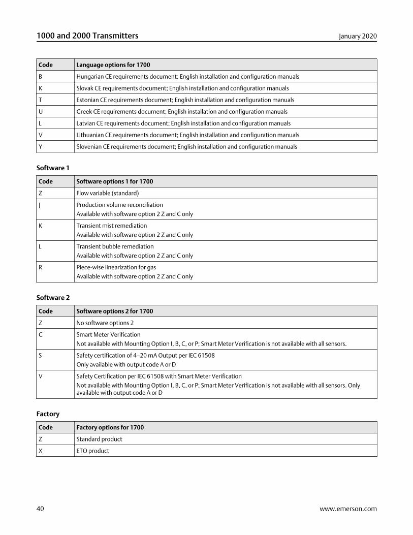
Code Language options for 1700
B Hungarian CE requirements document; English installation and configuration manuals
K Slovak CE requirements document; English installation and configuration manuals
T Estonian CE requirements document; English installation and configuration manuals
U Greek CE requirements document; English installation and configuration manuals
L Latvian CE requirements document; English installation and configuration manuals
V Lithuanian CE requirements document; English installation and configuration manuals
Y Slovenian CE requirements document; English installation and configuration manuals
Software 1
Code Software options 1 for 1700
Z Flow variable (standard)
J Production volume reconciliation
Available with software option 2 Z and C only
K Transient mist remediation
Available with software option 2 Z and C only
L Transient bubble remediation
Available with software option 2 Z and C only
R Piece-wise linearization for gas
Available with software option 2 Z and C only
Software 2
Code Software options 2 for 1700
Z No software options 2
C Smart Meter Verification
Not available with Mounting Option I, B, C, or P; Smart Meter Verification is not available with all sensors.
S Safety certification of 4–20 mA Output per IEC 61508
Only available with output code A or D
V Safety Certification per IEC 61508 with Smart Meter Verification
Not available with Mounting Option I, B, C, or P; Smart Meter Verification is not available with all sensors. Onlyavailable with output code A or D
Factory
Code Factory options for 1700
Z Standard product
X ETO product
1000 and 2000 Transmitters January 2020
40 www.emerson.com
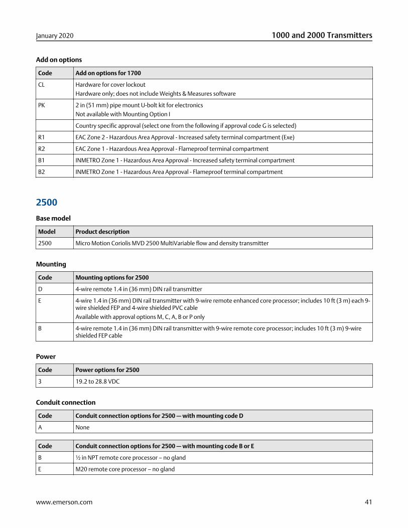
Add on options
Code Add on options for 1700
CL Hardware for cover lockout
Hardware only; does not include Weights & Measures software
PK 2 in (51 mm) pipe mount U-bolt kit for electronics
Not available with Mounting Option I
Country specific approval (select one from the following if approval code G is selected)
R1 EAC Zone 2 - Hazardous Area Approval - Increased safety terminal compartment (Exe)
R2 EAC Zone 1 - Hazardous Area Approval - Flameproof terminal compartment
B1 INMETRO Zone 1 - Hazardous Area Approval - Increased safety terminal compartment
B2 INMETRO Zone 1 - Hazardous Area Approval - Flameproof terminal compartment
2500
Base model
Model Product description
2500 Micro Motion Coriolis MVD 2500 MultiVariable flow and density transmitter
Mounting
Code Mounting options for 2500
D 4-wire remote 1.4 in (36 mm) DIN rail transmitter
E 4-wire 1.4 in (36 mm) DIN rail transmitter with 9-wire remote enhanced core processor; includes 10 ft (3 m) each 9-wire shielded FEP and 4-wire shielded PVC cable
Available with approval options M, C, A, B or P only
B 4-wire remote 1.4 in (36 mm) DIN rail transmitter with 9-wire remote core processor; includes 10 ft (3 m) 9-wireshielded FEP cable
Power
Code Power options for 2500
3 19.2 to 28.8 VDC
Conduit connection
Code Conduit connection options for 2500 — with mounting code D
A None
Code Conduit connection options for 2500 — with mounting code B or E
B ½ in NPT remote core processor – no gland
E M20 remote core processor – no gland
January 2020 1000 and 2000 Transmitters
www.emerson.com 41
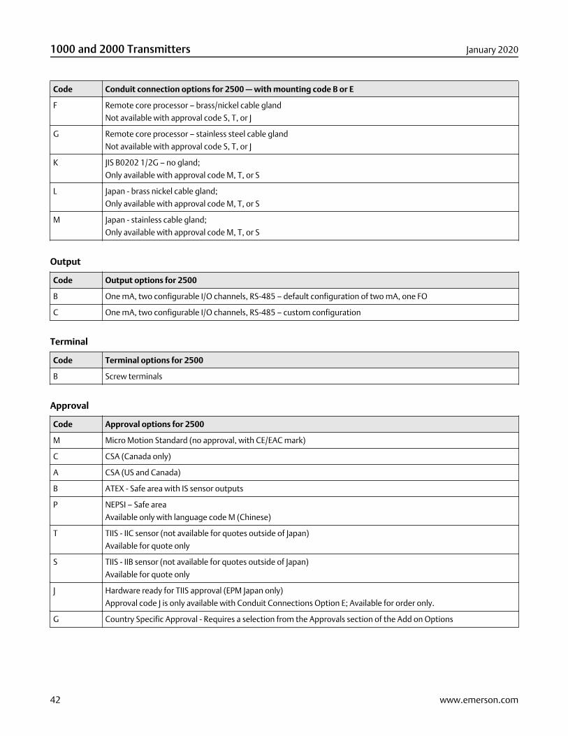
Code Conduit connection options for 2500 — with mounting code B or E
F Remote core processor – brass/nickel cable gland
Not available with approval code S, T, or J
G Remote core processor – stainless steel cable gland
Not available with approval code S, T, or J
K JIS B0202 1/2G – no gland;
Only available with approval code M, T, or S
L Japan - brass nickel cable gland;
Only available with approval code M, T, or S
M Japan - stainless cable gland;
Only available with approval code M, T, or S
Output
Code Output options for 2500
B One mA, two configurable I/O channels, RS-485 – default configuration of two mA, one FO
C One mA, two configurable I/O channels, RS-485 – custom configuration
Terminal
Code Terminal options for 2500
B Screw terminals
Approval
Code Approval options for 2500
M Micro Motion Standard (no approval, with CE/EAC mark)
C CSA (Canada only)
A CSA (US and Canada)
B ATEX - Safe area with IS sensor outputs
P NEPSI – Safe area
Available only with language code M (Chinese)
T TIIS - IIC sensor (not available for quotes outside of Japan)
Available for quote only
S TIIS - IIB sensor (not available for quotes outside of Japan)
Available for quote only
J Hardware ready for TIIS approval (EPM Japan only)
Approval code J is only available with Conduit Connections Option E; Available for order only.
G Country Specific Approval - Requires a selection from the Approvals section of the Add on Options
1000 and 2000 Transmitters January 2020
42 www.emerson.com
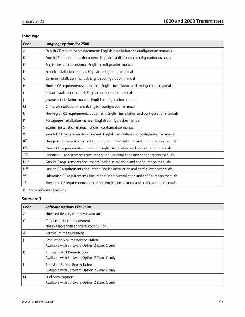
Language
Code Language options for 2500
A Danish CE requirements document; English installation and configuration manuals
D Dutch CE requirements document; English installation and configuration manuals
E English installation manual; English configuration manual
F French installation manual; English configuration manual
G German installation manual; English configuration manual
H Finnish CE requirements document; English installation and configuration manuals
I Italian installation manual; English configuration manual
J Japanese installation manual; English configuration manual
M Chinese installation manual; English configuration manual
N Norwegian CE requirements document; English installation and configuration manuals
P Portuguese installation manual; English configuration manual
S Spanish installation manual; English configuration manual
W Swedish CE requirements document; English installation and configuration manuals
B(1) Hungarian CE requirements document; English installation and configuration manuals
K(1) Slovak CE requirements document; English installation and configuration manuals
T(1) Estonian CE requirements document; English installation and configuration manuals
U(1) Greek CE requirements document; English installation and configuration manuals
L(1) Latvian CE requirements document; English installation and configuration manuals
V(1) Lithuanian CE requirements document; English installation and configuration manuals
Y(1) Slovenian CE requirements document; English installation and configuration manuals
(1) Not available with Approval T.
Software 1
Code Software options 1 for 2500
Z Flow and density variables (standard)
G Concentration measurement
Not available with approval code S, T or J
A Petroleum measurement
J Production Volume Reconciliation
Available with Software Option 2 Z and C only
K Transient Mist Remediation
Available with Software Option 2 Z and C only
L Transient Bubble Remediation
Available with Software Option 2 Z and C only
M Fuel consumption
Available with Software Option 2 Z and C only
January 2020 1000 and 2000 Transmitters
www.emerson.com 43
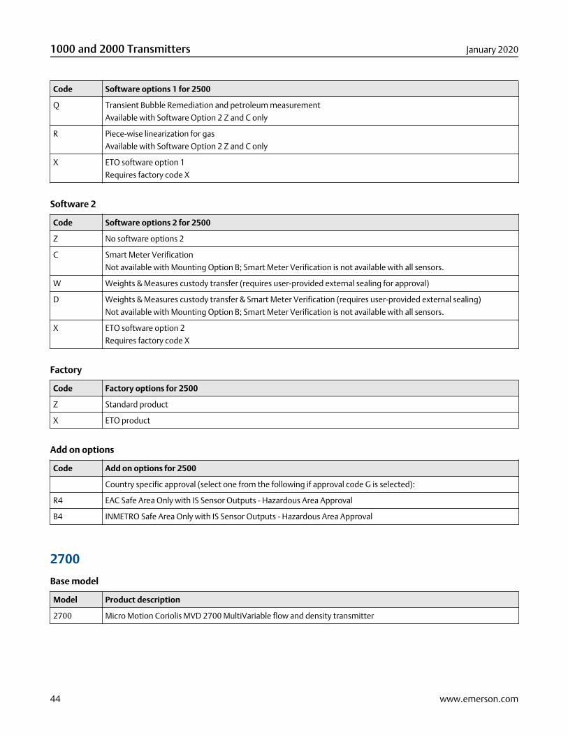
Code Software options 1 for 2500
Q Transient Bubble Remediation and petroleum measurement
Available with Software Option 2 Z and C only
R Piece-wise linearization for gas
Available with Software Option 2 Z and C only
X ETO software option 1
Requires factory code X
Software 2
Code Software options 2 for 2500
Z No software options 2
C Smart Meter Verification
Not available with Mounting Option B; Smart Meter Verification is not available with all sensors.
W Weights & Measures custody transfer (requires user-provided external sealing for approval)
D Weights & Measures custody transfer & Smart Meter Verification (requires user-provided external sealing)
Not available with Mounting Option B; Smart Meter Verification is not available with all sensors.
X ETO software option 2
Requires factory code X
Factory
Code Factory options for 2500
Z Standard product
X ETO product
Add on options
Code Add on options for 2500
Country specific approval (select one from the following if approval code G is selected):
R4 EAC Safe Area Only with IS Sensor Outputs - Hazardous Area Approval
B4 INMETRO Safe Area Only with IS Sensor Outputs - Hazardous Area Approval
2700
Base model
Model Product description
2700 Micro Motion Coriolis MVD 2700 MultiVariable flow and density transmitter
1000 and 2000 Transmitters January 2020
44 www.emerson.com
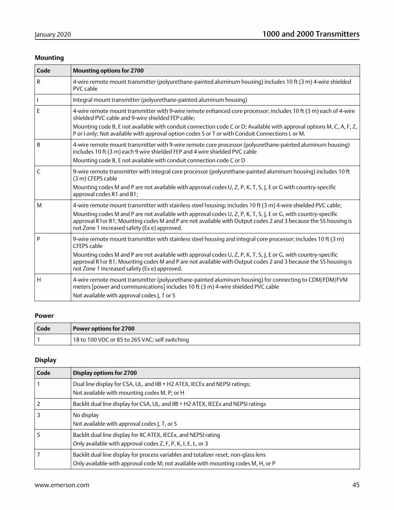
Mounting
Code Mounting options for 2700
R 4-wire remote mount transmitter (polyurethane-painted aluminum housing) includes 10 ft (3 m) 4-wire shieldedPVC cable
I Integral mount transmitter (polyurethane-painted aluminum housing)
E 4-wire remote mount transmitter with 9-wire remote enhanced core processor; includes 10 ft (3 m) each of 4-wireshielded PVC cable and 9-wire shielded FEP cable;
Mounting code B, E not available with conduit connection code C or D; Available with approval options M, C, A, F, Z,P or I only; Not available with approval option codes S or T or with Conduit Connections L or M.
B 4-wire remote mount transmitter with 9-wire remote core processor (polyurethane-painted aluminum housing)includes 10 ft (3 m) each 9 wire shielded FEP and 4 wire shielded PVC cable
Mounting code B, E not available with conduit connection code C or D
C 9-wire remote transmitter with integral core processor (polyurethane-painted aluminum housing) includes 10 ft(3 m) CFEPS cable
Mounting codes M and P are not available with approval codes U, Z, P, K, T, S, J, E or G with country-specificapproval codes R1 and B1;
M 4-wire remote mount transmitter with stainless steel housing; includes 10 ft (3 m) 4-wire shielded PVC cable;
Mounting codes M and P are not available with approval codes U, Z, P, K, T, S, J, E or G, with country-specificapproval R1or B1; Mounting codes M and P are not available with Output codes 2 and 3 because the SS housing isnot Zone 1 increased safety (Ex e) approved.
P 9-wire remote mount transmitter with stainless steel housing and integral core processor; includes 10 ft (3 m)CFEPS cable
Mounting codes M and P are not available with approval codes U, Z, P, K, T, S, J, E or G, with country-specificapproval R1or B1; Mounting codes M and P are not available with Output codes 2 and 3 because the SS housing isnot Zone 1 increased safety (Ex e) approved.
H 4-wire remote mount transmitter (polyurethane-painted aluminum housing) for connecting to CDM/FDM/FVMmeters [power and communications] includes 10 ft (3 m) 4-wire shielded PVC cable
Not available with approval codes J, T or S
Power
Code Power options for 2700
1 18 to 100 VDC or 85 to 265 VAC; self switching
Display
Code Display options for 2700
1 Dual line display for CSA, UL, and IIB + H2 ATEX, IECEx and NEPSI ratings;
Not available with mounting codes M, P; or H
2 Backlit dual line display for CSA, UL, and IIB + H2 ATEX, IECEx and NEPSI ratings
3 No display
Not available with approval codes J, T, or S
5 Backlit dual line display for IIC ATEX, IECEx, and NEPSI rating
Only available with approval codes Z, F, P, K, I, E, L, or 3
7 Backlit dual line display for process variables and totalizer reset, non-glass lens
Only available with approval code M; not available with mounting codes M, H, or P
January 2020 1000 and 2000 Transmitters
www.emerson.com 45
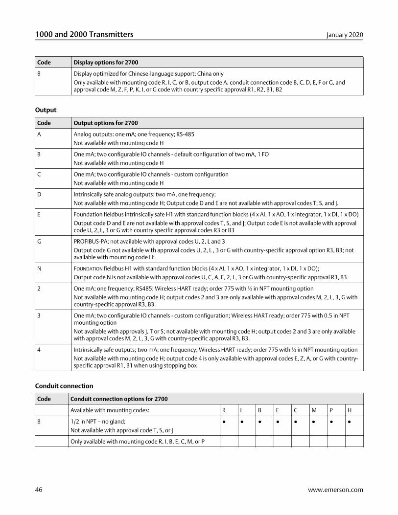
Code Display options for 2700
8 Display optimized for Chinese-language support; China only
Only available with mounting code R, I, C, or B, output code A, conduit connection code B, C, D, E, F or G, andapproval code M, Z, F, P, K, I, or G code with country specific approval R1, R2, B1, B2
Output
Code Output options for 2700
A Analog outputs: one mA; one frequency; RS-485
Not available with mounting code H
B One mA; two configurable IO channels - default configuration of two mA, 1 FO
Not available with mounting code H
C One mA; two configurable IO channels - custom configuration
Not available with mounting code H
D Intrinsically safe analog outputs: two mA, one frequency;
Not available with mounting code H; Output code D and E are not available with approval codes T, S, and J.
E Foundation fieldbus intrinsically safe H1 with standard function blocks (4 x AI, 1 x AO, 1 x integrator, 1 x DI, 1 x DO)
Output code D and E are not available with approval codes T, S, and J; Output code E is not available with approvalcode U, 2, L, 3 or G with country specific approval codes R3 or B3
G PROFIBUS-PA; not available with approval codes U, 2, L and 3
Output code G not available with approval codes U, 2, L , 3 or G with country-specific approval option R3, B3; notavailable with mounting code H:
N FOUNDATION fieldbus H1 with standard function blocks (4 x AI, 1 x AO, 1 x integrator, 1 x DI, 1 x DO);
Output code N is not available with approval codes U, C, A, E, 2, L, 3 or G with country-specific approval R3, B3
2 One mA; one frequency; RS485; Wireless HART ready; order 775 with ½ in NPT mounting option
Not available with mounting code H; output codes 2 and 3 are only available with approval codes M, 2, L, 3, G withcountry-specific approval R3, B3.
3 One mA; two configurable IO channels - custom configuration; Wireless HART ready; order 775 with 0.5 in NPTmounting option
Not available with approvals J, T or S; not available with mounting code H; output codes 2 and 3 are only availablewith approval codes M, 2, L, 3, G with country-specific approval R3, B3.
4 Intrinsically safe outputs; two mA; one frequency; Wireless HART ready; order 775 with ½ in NPT mounting option
Not available with mounting code H; output code 4 is only available with approval codes E, Z, A, or G with country-specific approval R1, B1 when using stopping box
Conduit connection
Code Conduit connection options for 2700
Available with mounting codes: R I B E C M P H
B 1/2 in NPT – no gland;
Not available with approval code T, S, or J
● ● ● ● ● ● ● ●
Only available with mounting code R, I, B, E, C, M, or P
1000 and 2000 Transmitters January 2020
46 www.emerson.com
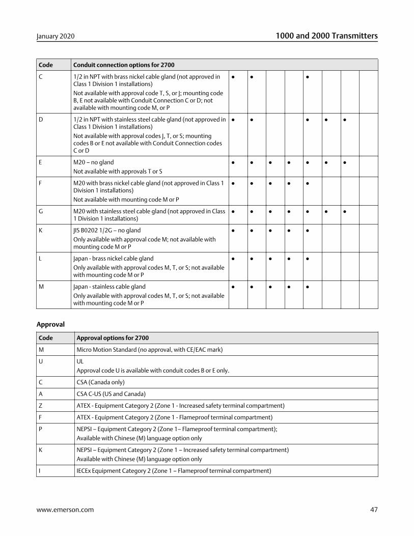
Code Conduit connection options for 2700
C 1/2 in NPT with brass nickel cable gland (not approved inClass 1 Division 1 installations)
Not available with approval code T, S, or J; mounting codeB, E not available with Conduit Connection C or D; notavailable with mounting code M, or P
● ● ●
D 1/2 in NPT with stainless steel cable gland (not approved inClass 1 Division 1 installations)
Not available with approval codes J, T, or S; mountingcodes B or E not available with Conduit Connection codesC or D
● ● ● ● ●
E M20 – no gland
Not available with approvals T or S
● ● ● ● ● ● ●
F M20 with brass nickel cable gland (not approved in Class 1Division 1 installations)
Not available with mounting code M or P
● ● ● ● ●
G M20 with stainless steel cable gland (not approved in Class1 Division 1 installations)
● ● ● ● ● ● ●
K JIS B0202 1/2G – no gland
Only available with approval code M; not available withmounting code M or P
● ● ● ● ●
L Japan - brass nickel cable gland
Only available with approval codes M, T, or S; not availablewith mounting code M or P
● ● ● ● ●
M Japan - stainless cable gland
Only available with approval codes M, T, or S; not availablewith mounting code M or P
● ● ● ● ●
Approval
Code Approval options for 2700
M Micro Motion Standard (no approval, with CE/EAC mark)
U UL
Approval code U is available with conduit codes B or E only.
C CSA (Canada only)
A CSA C-US (US and Canada)
Z ATEX - Equipment Category 2 (Zone 1 - Increased safety terminal compartment)
F ATEX - Equipment Category 2 (Zone 1 - Flameproof terminal compartment)
P NEPSI – Equipment Category 2 (Zone 1– Flameproof terminal compartment);
Available with Chinese (M) language option only
K NEPSI – Equipment Category 2 (Zone 1 – Increased safety terminal compartment)
Available with Chinese (M) language option only
I IECEx Equipment Category 2 (Zone 1 – Flameproof terminal compartment)
January 2020 1000 and 2000 Transmitters
www.emerson.com 47
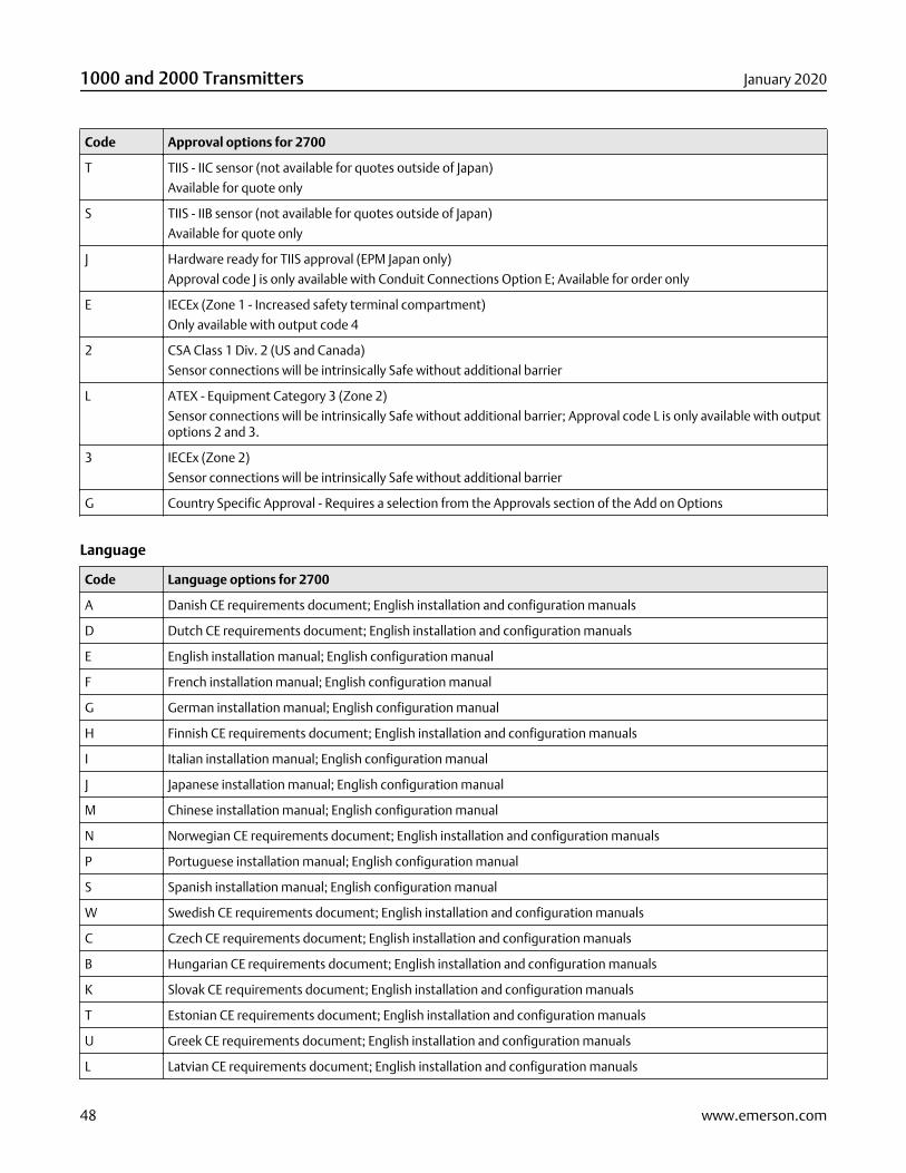
Code Approval options for 2700
T TIIS - IIC sensor (not available for quotes outside of Japan)
Available for quote only
S TIIS - IIB sensor (not available for quotes outside of Japan)
Available for quote only
J Hardware ready for TIIS approval (EPM Japan only)
Approval code J is only available with Conduit Connections Option E; Available for order only
E IECEx (Zone 1 - Increased safety terminal compartment)
Only available with output code 4
2 CSA Class 1 Div. 2 (US and Canada)
Sensor connections will be intrinsically Safe without additional barrier
L ATEX - Equipment Category 3 (Zone 2)
Sensor connections will be intrinsically Safe without additional barrier; Approval code L is only available with outputoptions 2 and 3.
3 IECEx (Zone 2)
Sensor connections will be intrinsically Safe without additional barrier
G Country Specific Approval - Requires a selection from the Approvals section of the Add on Options
Language
Code Language options for 2700
A Danish CE requirements document; English installation and configuration manuals
D Dutch CE requirements document; English installation and configuration manuals
E English installation manual; English configuration manual
F French installation manual; English configuration manual
G German installation manual; English configuration manual
H Finnish CE requirements document; English installation and configuration manuals
I Italian installation manual; English configuration manual
J Japanese installation manual; English configuration manual
M Chinese installation manual; English configuration manual
N Norwegian CE requirements document; English installation and configuration manuals
P Portuguese installation manual; English configuration manual
S Spanish installation manual; English configuration manual
W Swedish CE requirements document; English installation and configuration manuals
C Czech CE requirements document; English installation and configuration manuals
B Hungarian CE requirements document; English installation and configuration manuals
K Slovak CE requirements document; English installation and configuration manuals
T Estonian CE requirements document; English installation and configuration manuals
U Greek CE requirements document; English installation and configuration manuals
L Latvian CE requirements document; English installation and configuration manuals
1000 and 2000 Transmitters January 2020
48 www.emerson.com
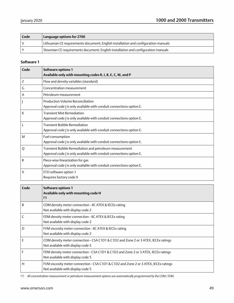
Code Language options for 2700
V Lithuanian CE requirements document; English installation and configuration manuals
Y Slovenian CE requirements document; English installation and configuration manuals
Software 1
Code Software options 1
Available only with mounting codes R, I, B, E, C, M, and P
Z Flow and density variables (standard)
G Concentration measurement
A Petroleum measurement
J Production Volume Reconciliation
Approval code J is only available with conduit connections option E.
K Transient Mist Remediation
Approval code J is only available with conduit connections option E.
L Transient Bubble Remediation
Approval code J is only available with conduit connections option E.
M Fuel consumption
Approval code J is only available with conduit connections option E.
Q Transient Bubble Remediation and petroleum measurement
Approval code J is only available with conduit connections option E.
R Piece-wise linearization for gas
Approval code J is only available with conduit connections option E.
X ETO software option 1
Requires factory code X
Code Software options 1
Available only with mounting code H(1)
B CDM density meter connection - IIC ATEX & IECEx rating
Not available with display code 2
C FDM density meter connection - IIC ATEX & IECEx rating
Not available with display code 2
D FVM viscosity meter connection - IIC ATEX & IECEx rating
Not available with display code 2
E CDM density meter connection - CSA C1D1 & C1D2 and Zone 2 or 3 ATEX, IECEx ratings
Not available with display code 5
F FDM density meter connection - CSA C1D1 & C1D2 and Zone 2 or 3 ATEX, IECEx ratings
Not available with display code 5
H FVM viscosity meter connection - CSA C1D1 & C1D2 and Zone 2 or 3 ATEX, IECEx ratings
Not available with display code 5
(1) All concentration measurement or petroleum measurement options are automatically programmed by the CDM / FDM.
January 2020 1000 and 2000 Transmitters
www.emerson.com 49
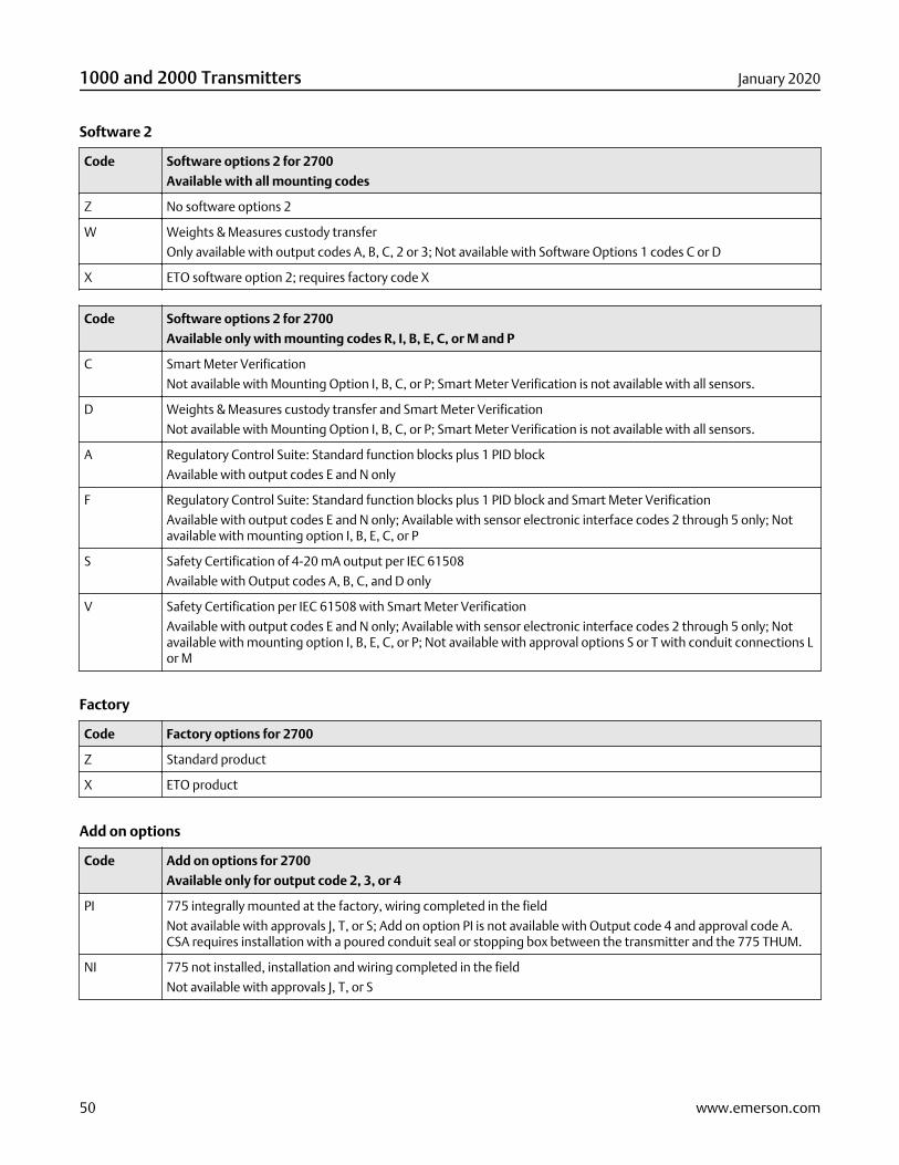
Software 2
Code Software options 2 for 2700
Available with all mounting codes
Z No software options 2
W Weights & Measures custody transfer
Only available with output codes A, B, C, 2 or 3; Not available with Software Options 1 codes C or D
X ETO software option 2; requires factory code X
Code Software options 2 for 2700
Available only with mounting codes R, I, B, E, C, or M and P
C Smart Meter Verification
Not available with Mounting Option I, B, C, or P; Smart Meter Verification is not available with all sensors.
D Weights & Measures custody transfer and Smart Meter Verification
Not available with Mounting Option I, B, C, or P; Smart Meter Verification is not available with all sensors.
A Regulatory Control Suite: Standard function blocks plus 1 PID block
Available with output codes E and N only
F Regulatory Control Suite: Standard function blocks plus 1 PID block and Smart Meter Verification
Available with output codes E and N only; Available with sensor electronic interface codes 2 through 5 only; Notavailable with mounting option I, B, E, C, or P
S Safety Certification of 4-20 mA output per IEC 61508
Available with Output codes A, B, C, and D only
V Safety Certification per IEC 61508 with Smart Meter Verification
Available with output codes E and N only; Available with sensor electronic interface codes 2 through 5 only; Notavailable with mounting option I, B, E, C, or P; Not available with approval options S or T with conduit connections Lor M
Factory
Code Factory options for 2700
Z Standard product
X ETO product
Add on options
Code Add on options for 2700
Available only for output code 2, 3, or 4
PI 775 integrally mounted at the factory, wiring completed in the field
Not available with approvals J, T, or S; Add on option PI is not available with Output code 4 and approval code A.CSA requires installation with a poured conduit seal or stopping box between the transmitter and the 775 THUM.
NI 775 not installed, installation and wiring completed in the field
Not available with approvals J, T, or S
1000 and 2000 Transmitters January 2020
50 www.emerson.com
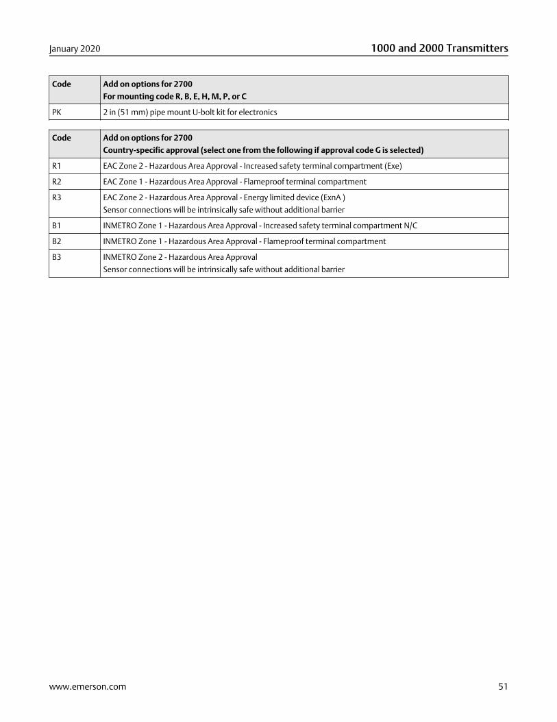
Code Add on options for 2700
For mounting code R, B, E, H, M, P, or C
PK 2 in (51 mm) pipe mount U-bolt kit for electronics
Code Add on options for 2700
Country-specific approval (select one from the following if approval code G is selected)
R1 EAC Zone 2 - Hazardous Area Approval - Increased safety terminal compartment (Exe)
R2 EAC Zone 1 - Hazardous Area Approval - Flameproof terminal compartment
R3 EAC Zone 2 - Hazardous Area Approval - Energy limited device (ExnA )
Sensor connections will be intrinsically safe without additional barrier
B1 INMETRO Zone 1 - Hazardous Area Approval - Increased safety terminal compartment N/C
B2 INMETRO Zone 1 - Hazardous Area Approval - Flameproof terminal compartment
B3 INMETRO Zone 2 - Hazardous Area Approval
Sensor connections will be intrinsically safe without additional barrier
January 2020 1000 and 2000 Transmitters
www.emerson.com 51
PS-00400Rev. X
January 2020
Emerson Automation SolutionsWorldwide Headquarters7070 Winchester CircleBoulder, Colorado USA 80301T: +1 800-522-6277T: +1 303-527-5200F: +1 303-530-8459Mexico: +52 55 5809 5300Argentina: +54 11 4837 7000Brazil: +55 15 3413 8000Chile: +56 2 2928 4800Peru: +51 15190130
Emerson Automation SolutionsCentral Europe: +41 41 7686 111Eastern Europe: +41 41 7686 111Dubai: +971 4 811 8100Abu Dhabi: +971 2 697 2000Austria: +43 2236 607-0France: +33 (0) 800 917 901Germany: +49 (0) 2173 3348 0Italy: +39 8008 77334The Netherlands: +31 318 495 555Belgium: +32 2 716 77 11Spain: 900 901 983U.K. and Ireland: 0870 240 1978Russian/CIS: +7 495 995 9559
Emerson Automation SolutionsAustralia: (61) 3 9721 0200China: (86) 21 2892 9000India: (91) 22 6662 0566Japan: (81) 3 5769 6803South Korea: (82) 31 8034 0000Singapore: (65) 6 363 7766
©2020 Micro Motion, Inc. All rights reserved.
The Emerson logo is a trademark and service mark of Emerson Electric Co. Micro Motion, ELITE,ProLink, MVD and MVD Direct Connect marks are marks of one of the Emerson AutomationSolutions family of companies. All other marks are property of their respective owners.