Embed Size (px)
DESCRIPTION
Description about building a robot for micromouse competition.
Citation preview
PROJECT: Micromouse (December 2009-February 2010)
Details: This aim of this project was to develop a maze solving robot that would participate in a national level competition. The rules of the competition are of global standards as specified by the IEEE.
The grid consists of 16x16 squares with walls on some part and open on others so that one can eventually find a way from the start point (located at coordinates 0,0) to the center of the maze (located at coordinates 8,8) by travelling through zones not containing walls.
The maze is composed of multiples of an 18 cm x 18 cm unit square. The maze comprises 16 x 16 unit squares. The walls of the maze are 5 cm high and 1.2 cm thick
The start of the maze is located at one of the four corners (assumed here as 0,0). It is bounded on 3 sides by walls.
The motion of the robot may be of the following types: Forward, Backward/U-turn,Left turn, Right Turn.
The robot must be completely autonomous
The robot must reach the center in the least possible time
No external power source is allowed.
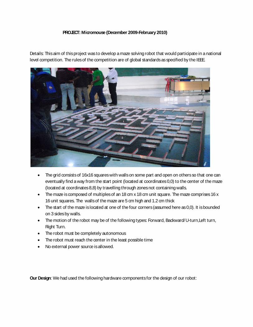
Our Design: We had used the following hardware components for the design of our robot:
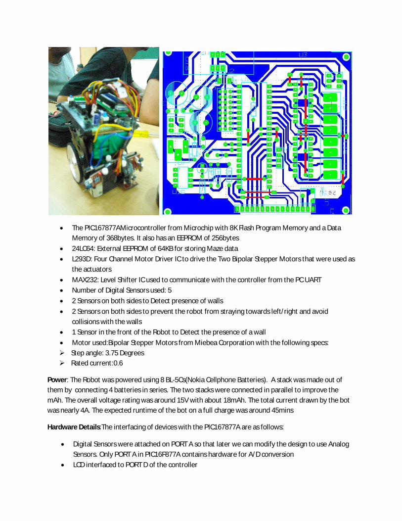
The PIC167877AMicrocontroller from Microchip with 8K Flash Program Memory and a Data Memory of 368bytes. It also has an EEPROM of 256bytes
24LC64: External EEPROM of 64KB for storing Maze data
L293D: Four Channel Motor Driver IC to drive the Two Bipolar Stepper Motors that were used as the actuators
MAX232: Level Shifter IC used to communicate with the controller from the PC UART
Number of Digital Sensors used: 5
2 Sensors on both sides to Detect presence of walls
2 Sensors on both sides to prevent the robot from straying towards left/right and avoid collisions with the walls
1 Sensor in the front of the Robot to Detect the presence of a wall
Motor used:Bipolar Stepper Motors from Miebea Corporation with the following specs: Step angle: 3.75 Degrees Rated current:0.6
Power: The Robot was powered using 8 BL-5Cs(Nokia Cellphone Batteries). A stack was made out of them by connecting 4 batteries in series. The two stacks were connected in parallel to improve the mAh. The overall voltage rating was around 15V with about 18mAh. The total current drawn by the bot was nearly 4A. The expected runtime of the bot on a full charge was around 45mins
Hardware Details:The interfacing of devices with the PIC167877A are as follows:
Digital Sensors were attached on PORT A so that later we can modify the design to use Analog Sensors. Only PORT A in PIC16F877A contains hardware for A/D conversion
LCD interfaced to PORT D of the controller
EEPROM Module attached to the SCK and SDO of the Controller.
Motors were attached to PORT B of the Controller via L293D Motor Driver IC
Software Details: The entire code was written in PIC C compiler and loaded onto the controller using the PIC Downloader
Application. The Code details are as follows:
The Code consited of twoprimary layers:
The Motion Layer: It is comprised of Code that controls the motion of the robot. The Code from the Logic layer calls this layer to move the robot from one cell to another as and when required. This layer would also automatically correct the motion of the robot if it has strayed towards left or right.
The Logic Layer: This layer consisted of logic code that would help the robot decide which cell to move towards on the basis of the sensor data that it recieved. The logic that guided the robot comprised of a Depth First Search Algorithm aided by a Heuristic that would reduce and optimize the results from the DFS. The cells were assigned potential values such that the cells lower to the centre would have lower potential values. The heuristic utilized these potential values to guide the robot.
We later came across a paper named Center First Routing Theorem in Micromouse. We found the algorithm published in a 2008 IEEE paper by Yifeng Chen, Hengkai Zhao, Wanggen Wan, Xiaoqing Yu from School of Communication and Information Engineering, Shanghai University. The Performance of our code was actually comparable to the performance of the Centre First Routing Theorem!
Competition Results: We stood first among all the competing teams at NIT Trichy(February 2010)
Email:[email protected] ayushdewan.wordpress.com