Embed Size (px)
Citation preview
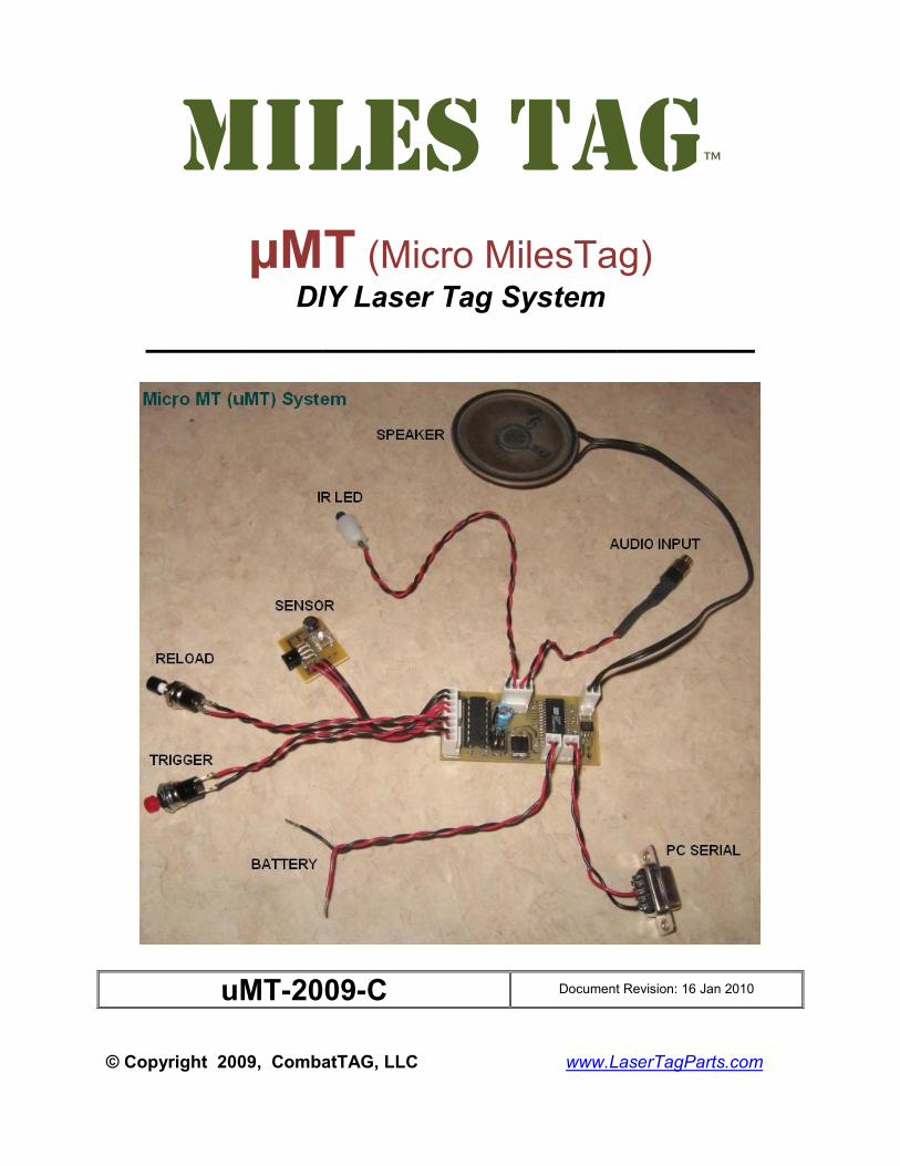
MILES TAG™
µMT (Micro MilesTag) DIY Laser Tag System
_______________________________
uMT-2009-C Document Revision: 16 Jan 2010
© Copyright 2009, CombatTAG, LLC www.LaserTagParts.com
NOTICE: This document and the systems described herein are protected by international copyright laws.
It may not be reproduced in full or in part, for any purpose public or private, without the express written
consent of the author. All features, specifications and information detailed in this publication are subject
to change without notice. Use of the information and the systems described is entirely at your own risk.
The author assumes no liability for injury to persons or damage to property and equipment resulting from
the use and or misuse of the information, procedures, circuits and systems described. The author also
assumes no liability for typographical errors or omissions.
DISCLAIMER OF WARRANTIES & LIMITATION OF LIABILITY
Combat TAG, LLC makes no warranty, either express or implied with respect to any product or service,
and specifically disclaims all other warranties, including, without limitation, warranties for merchantability,
non-infringement and fitness for any particular purpose. Combat TAG's sole obligation and liability for
product defects shall be, at Combat TAG's option, to replace such defective product or refund to buyer
the amount paid by the buyer therefore. In no event shall Combat TAG's liability exceed the buyer's
purchase price. The foregoing remedy shall be subject to the buyer's written notification of defect and
return of the defective product within ninety (90) days of purchase (date of invoice). The foregoing
remedy does not apply to products that have been subjected to misuse (including without limitation static
discharge), neglect, accident or modification, or to products that have been soldered or altered during
assembly, or are otherwise not capable of being tested, or if damage occurs as a result of the failure of
buyer to follow specific instructions. In no event shall Combat TAG be liable to the buyer or to any third
party for any indirect, incidental, special, consequential, punitive or exemplary damages (including without
limitation lost profits, lost savings, or loss of business opportunity) arising out of or relating to any product
or service provided or to be provided by Combat TAG, or the use or inability to use the same, even if
Combat TAG has been advised of the possibility of such damages.
“Laser Tag Parts” and “MilesTag™” are alternate business names of Combat TAG, LLC.
www.lasertagparts.com
www.CombatTAG.com
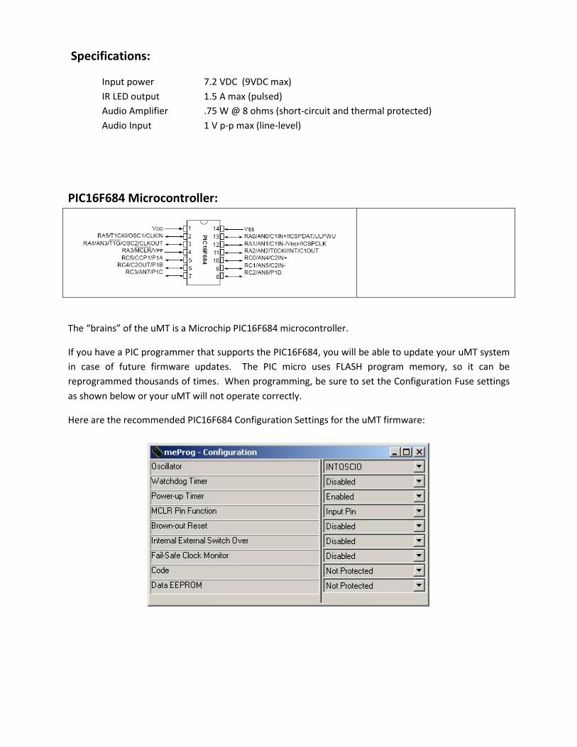
Specifications:
Input power 7.2 VDC (9VDC max)
IR LED output 1.5 A max (pulsed)
Audio Amplifier .75 W @ 8 ohms (short-circuit and thermal protected)
Audio Input 1 V p-p max (line-level)
PIC16F684 Microcontroller:
The “brains” of the uMT is a Microchip PIC16F684 microcontroller.
If you have a PIC programmer that supports the PIC16F684, you will be able to update your uMT system
in case of future firmware updates. The PIC micro uses FLASH program memory, so it can be
reprogrammed thousands of times. When programming, be sure to set the Configuration Fuse settings
as shown below or your uMT will not operate correctly.
Here are the recommended PIC16F684 Configuration Settings for the uMT firmware:
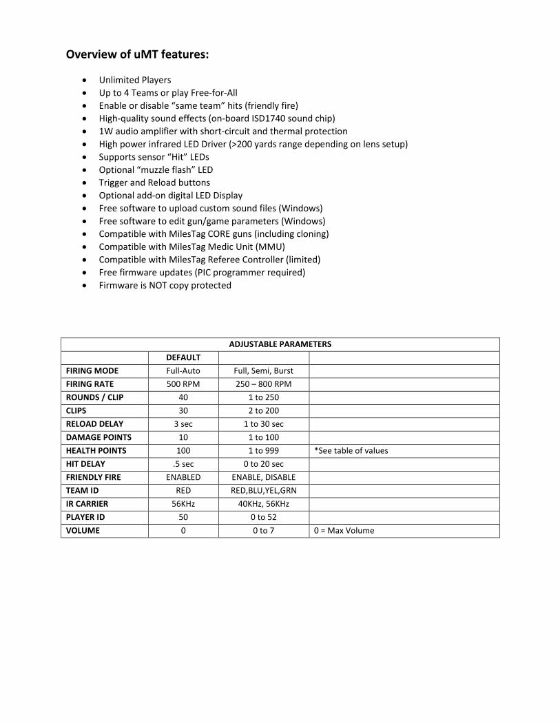
Overview of uMT features:
• Unlimited Players
• Up to 4 Teams or play Free-for-All
• Enable or disable “same team” hits (friendly fire)
• High-quality sound effects (on-board ISD1740 sound chip)
• 1W audio amplifier with short-circuit and thermal protection
• High power infrared LED Driver (>200 yards range depending on lens setup)
• Supports sensor “Hit” LEDs
• Optional “muzzle flash” LED
• Trigger and Reload buttons
• Optional add-on digital LED Display
• Free software to upload custom sound files (Windows)
• Free software to edit gun/game parameters (Windows)
• Compatible with MilesTag CORE guns (including cloning)
• Compatible with MilesTag Medic Unit (MMU)
• Compatible with MilesTag Referee Controller (limited)
• Free firmware updates (PIC programmer required)
• Firmware is NOT copy protected
ADJUSTABLE PARAMETERS
DEFAULT
FIRING MODE Full-Auto Full, Semi, Burst
FIRING RATE 500 RPM 250 – 800 RPM
ROUNDS / CLIP 40 1 to 250
CLIPS 30 2 to 200
RELOAD DELAY 3 sec 1 to 30 sec
DAMAGE POINTS 10 1 to 100
HEALTH POINTS 100 1 to 999 *See table of values
HIT DELAY .5 sec 0 to 20 sec
FRIENDLY FIRE ENABLED ENABLE, DISABLE
TEAM ID RED RED,BLU,YEL,GRN
IR CARRIER 56KHz 40KHz, 56KHz
PLAYER ID 50 0 to 52
VOLUME 0 0 to 7 0 = Max Volume
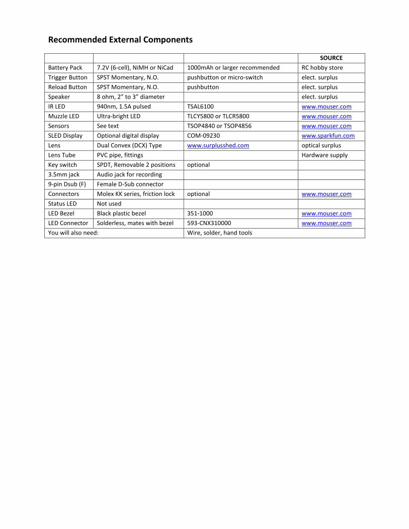
Recommended External Components
SOURCE
Battery Pack 7.2V (6-cell), NiMH or NiCad 1000mAh or larger recommended RC hobby store
Trigger Button SPST Momentary, N.O. pushbutton or micro-switch elect. surplus
Reload Button SPST Momentary, N.O. pushbutton elect. surplus
Speaker 8 ohm, 2” to 3” diameter elect. surplus
IR LED 940nm, 1.5A pulsed TSAL6100 www.mouser.com
Muzzle LED Ultra-bright LED TLCY5800 or TLCR5800 www.mouser.com
Sensors See text TSOP4840 or TSOP4856 www.mouser.com
SLED Display Optional digital display COM-09230 www.sparkfun.com
Lens Dual Convex (DCX) Type www.surplusshed.com optical surplus
Lens Tube PVC pipe, fittings Hardware supply
Key switch SPDT, Removable 2 positions optional
3.5mm jack Audio jack for recording
9-pin Dsub (F) Female D-Sub connector
Connectors Molex KK series, friction lock optional www.mouser.com
Status LED Not used
LED Bezel Black plastic bezel 351-1000 www.mouser.com
LED Connector Solderless, mates with bezel 593-CNX310000 www.mouser.com
You will also need: Wire, solder, hand tools
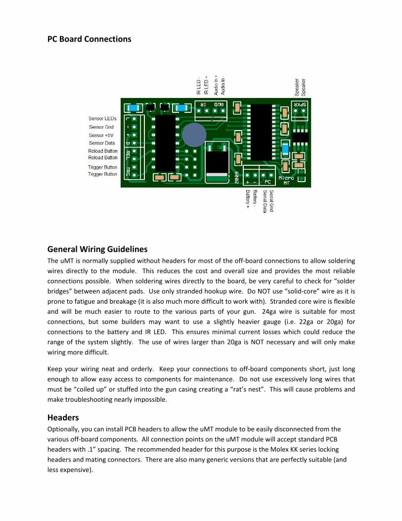
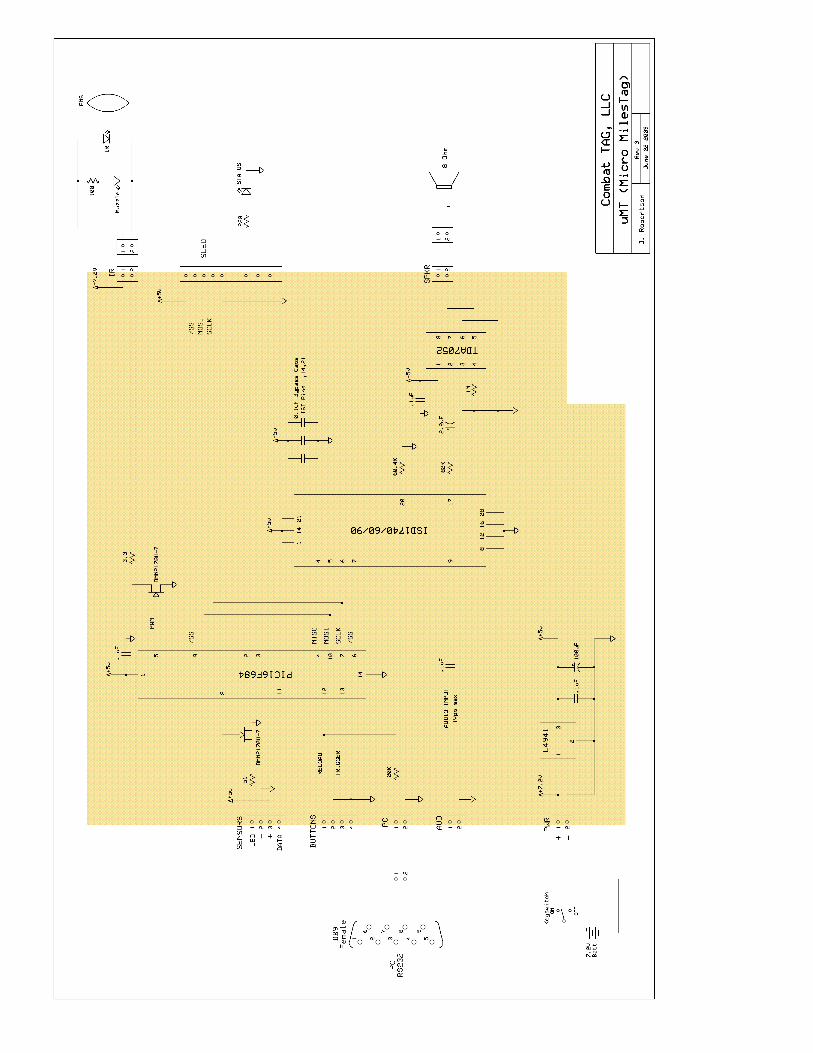
PC Board Connections
General Wiring Guidelines
The uMT is normally supplied without headers for most of the off-board connections to allow soldering
wires directly to the module. This reduces the cost and overall size and provides the most reliable
connections possible. When soldering wires directly to the board, be very careful to check for “solder
bridges” between adjacent pads. Use only stranded hookup wire. Do NOT use “solid-core” wire as it is
prone to fatigue and breakage (it is also much more difficult to work with). Stranded core wire is flexible
and will be much easier to route to the various parts of your gun. 24ga wire is suitable for most
connections, but some builders may want to use a slightly heavier gauge (i.e. 22ga or 20ga) for
connections to the battery and IR LED. This ensures minimal current losses which could reduce the
range of the system slightly. The use of wires larger than 20ga is NOT necessary and will only make
wiring more difficult.
Keep your wiring neat and orderly. Keep your connections to off-board components short, just long
enough to allow easy access to components for maintenance. Do not use excessively long wires that
must be “coiled up” or stuffed into the gun casing creating a “rat’s nest”. This will cause problems and
make troubleshooting nearly impossible.
Headers
Optionally, you can install PCB headers to allow the uMT module to be easily disconnected from the
various off-board components. All connection points on the uMT module will accept standard PCB
headers with .1” spacing. The recommended header for this purpose is the Molex KK series locking
headers and mating connectors. There are also many generic versions that are perfectly suitable (and
less expensive).
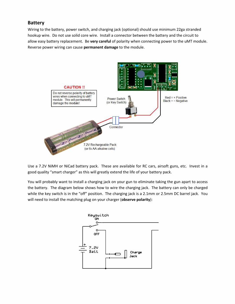
Battery
Wiring to the battery, power switch, and charging jack (optional) should use minimum 22ga stranded
hookup wire. Do not use solid core wire. Install a connector between the battery and the circuit to
allow easy battery replacement. Be very careful of polarity when connecting power to the uMT module.
Reverse power wiring can cause permanent damage to the module.
Use a 7.2V NiMH or NiCad battery pack. These are available for RC cars, airsoft guns, etc. Invest in a
good quality “smart charger” as this will greatly extend the life of your battery pack.
You will probably want to install a charging jack on your gun to eliminate taking the gun apart to access
the battery. The diagram below shows how to wire the charging jack. The battery can only be charged
while the key switch is in the “off” position. The charging jack is a 2.1mm or 2.5mm DC barrel jack. You
will need to install the matching plug on your charger (observe polarity):
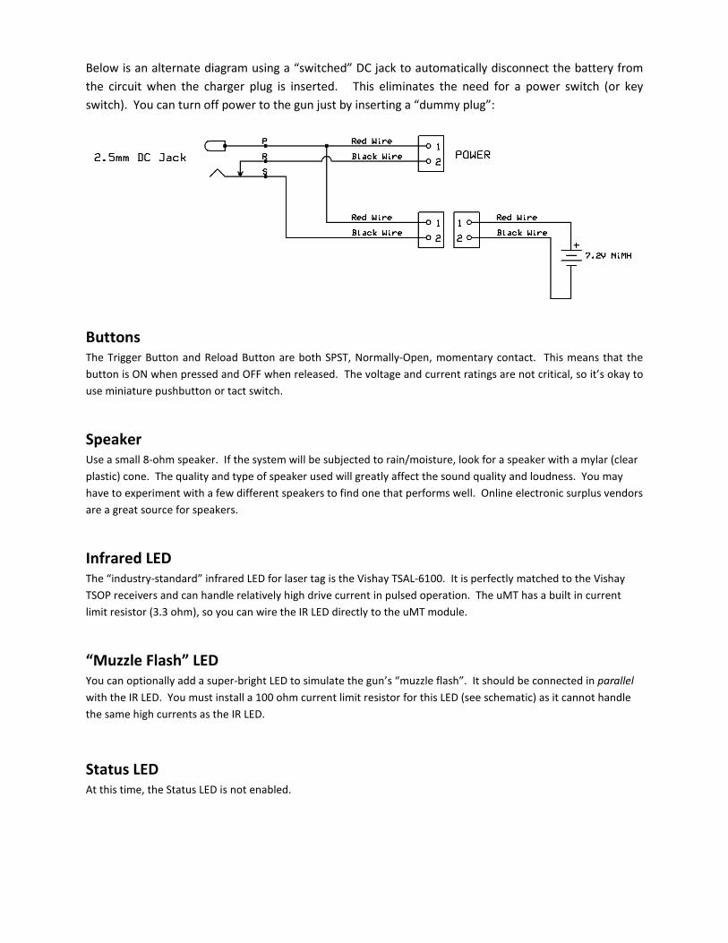
Below is an alternate diagram using a “switched” DC jack to automatically disconnect the battery from
the circuit when the charger plug is inserted. This eliminates the need for a power switch (or key
switch). You can turn off power to the gun just by inserting a “dummy plug”:
Buttons The Trigger Button and Reload Button are both SPST, Normally-Open, momentary contact. This means that the
button is ON when pressed and OFF when released. The voltage and current ratings are not critical, so it’s okay to
use miniature pushbutton or tact switch.
Speaker Use a small 8-ohm speaker. If the system will be subjected to rain/moisture, look for a speaker with a mylar (clear
plastic) cone. The quality and type of speaker used will greatly affect the sound quality and loudness. You may
have to experiment with a few different speakers to find one that performs well. Online electronic surplus vendors
are a great source for speakers.
Infrared LED The “industry-standard” infrared LED for laser tag is the Vishay TSAL-6100. It is perfectly matched to the Vishay
TSOP receivers and can handle relatively high drive current in pulsed operation. The uMT has a built in current
limit resistor (3.3 ohm), so you can wire the IR LED directly to the uMT module.
“Muzzle Flash” LED You can optionally add a super-bright LED to simulate the gun’s “muzzle flash”. It should be connected in parallel
with the IR LED. You must install a 100 ohm current limit resistor for this LED (see schematic) as it cannot handle
the same high currents as the IR LED.
Status LED At this time, the Status LED is not enabled.
Sensors The uMT is compatible with 40KHz or 56KHz infrared receivers (TSOP4840, TSOP4856). Just make sure ALL of your
guns use the same carrier frequency or they will not work together. You can mount the sensors on your gun, a
headband or both. Most people use 2 or 3 sensor domes on a headband. Each dome can have 1, 2 or 3 IR
receivers installed. If you place multiple receivers in a dome, set them at different angles to create a wider
sensitivity pattern.
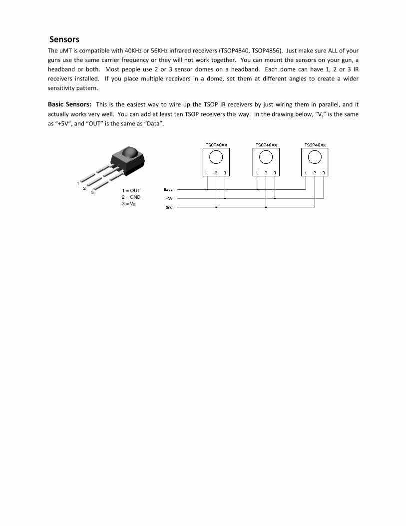
Basic Sensors: This is the easiest way to wire up the TSOP IR receivers by just wiring them in parallel, and it
actually works very well. You can add at least ten TSOP receivers this way. In the drawing below, “Vs” is the same
as “+5V”, and “OUT” is the same as “Data”.
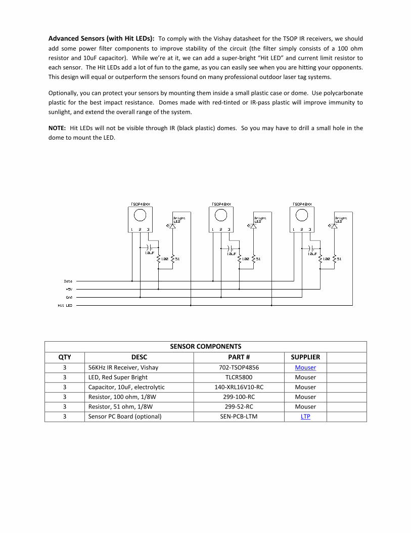
Advanced Sensors (with Hit LEDs): To comply with the Vishay datasheet for the TSOP IR receivers, we should
add some power filter components to improve stability of the circuit (the filter simply consists of a 100 ohm
resistor and 10uF capacitor). While we’re at it, we can add a super-bright “Hit LED” and current limit resistor to
each sensor. The Hit LEDs add a lot of fun to the game, as you can easily see when you are hitting your opponents.
This design will equal or outperform the sensors found on many professional outdoor laser tag systems.
Optionally, you can protect your sensors by mounting them inside a small plastic case or dome. Use polycarbonate
plastic for the best impact resistance. Domes made with red-tinted or IR-pass plastic will improve immunity to
sunlight, and extend the overall range of the system.
NOTE: Hit LEDs will not be visible through IR (black plastic) domes. So you may have to drill a small hole in the
dome to mount the LED.
SENSOR COMPONENTS
QTY DESC PART # SUPPLIER
3 56KHz IR Receiver, Vishay 702-TSOP4856 Mouser
3 LED, Red Super Bright TLCR5800 Mouser
3 Capacitor, 10uF, electrolytic 140-XRL16V10-RC Mouser
3 Resistor, 100 ohm, 1/8W 299-100-RC Mouser
3 Resistor, 51 ohm, 1/8W 299-52-RC Mouser
3 Sensor PC Board (optional) SEN-PCB-LTM LTP
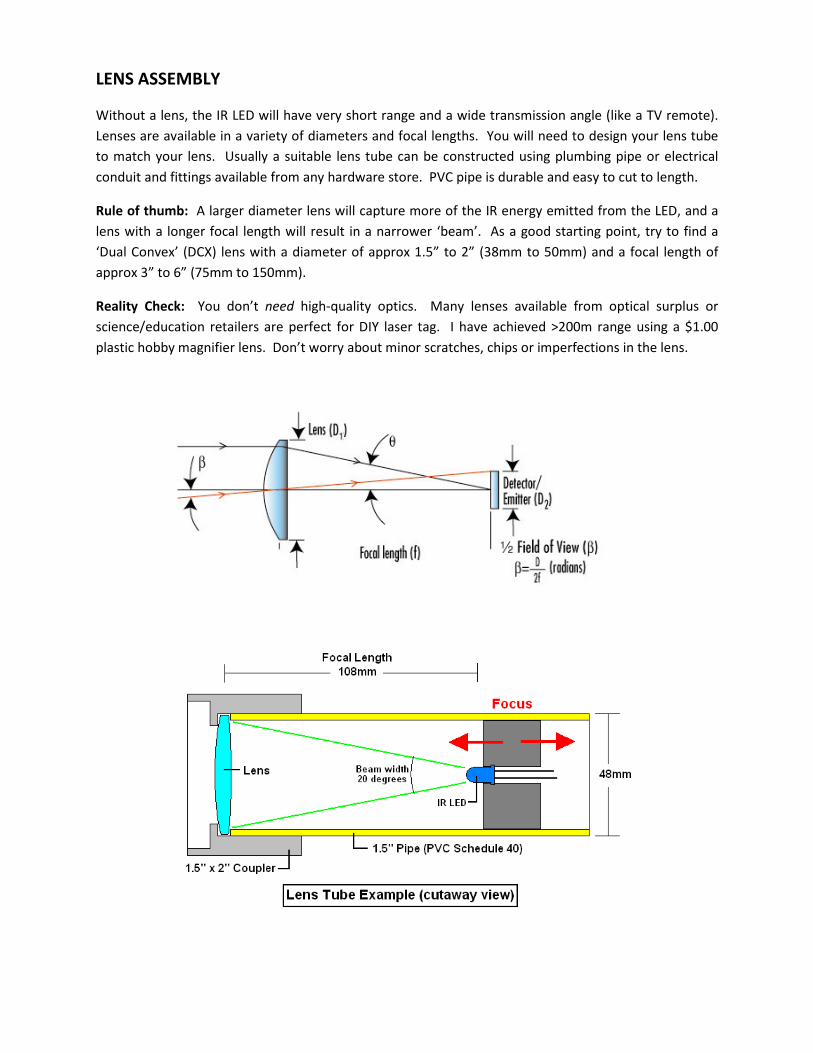
LENS ASSEMBLY
Without a lens, the IR LED will have very short range and a wide transmission angle (like a TV remote).
Lenses are available in a variety of diameters and focal lengths. You will need to design your lens tube
to match your lens. Usually a suitable lens tube can be constructed using plumbing pipe or electrical
conduit and fittings available from any hardware store. PVC pipe is durable and easy to cut to length.
Rule of thumb: A larger diameter lens will capture more of the IR energy emitted from the LED, and a
lens with a longer focal length will result in a narrower ‘beam’. As a good starting point, try to find a
‘Dual Convex’ (DCX) lens with a diameter of approx 1.5” to 2” (38mm to 50mm) and a focal length of
approx 3” to 6” (75mm to 150mm).
Reality Check: You don’t need high-quality optics. Many lenses available from optical surplus or
science/education retailers are perfect for DIY laser tag. I have achieved >200m range using a $1.00
plastic hobby magnifier lens. Don’t worry about minor scratches, chips or imperfections in the lens.
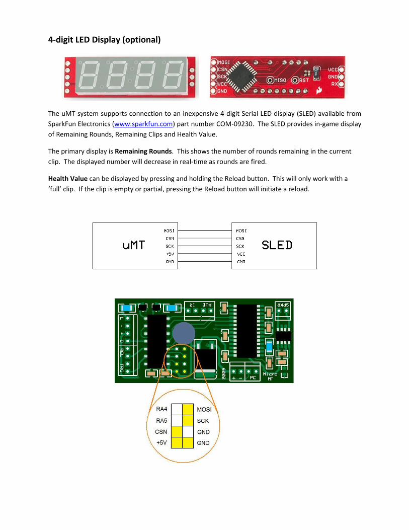
4-digit LED Display (optional)
The uMT system supports connection to an inexpensive 4-digit Serial LED display (SLED) available from
SparkFun Electronics (www.sparkfun.com) part number COM-09230. The SLED provides in-game display
of Remaining Rounds, Remaining Clips and Health Value.
The primary display is Remaining Rounds. This shows the number of rounds remaining in the current
clip. The displayed number will decrease in real-time as rounds are fired.
Health Value can be displayed by pressing and holding the Reload button. This will only work with a
‘full’ clip. If the clip is empty or partial, pressing the Reload button will initiate a reload.
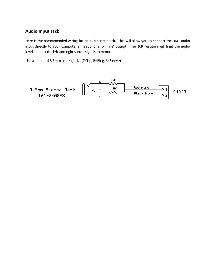
Audio Input Jack
Here is the recommended wiring for an audio input jack. This will allow you to connect the uMT audio
input directly to your computer’s ‘headphone’ or ‘line’ output. The 10K resistors will limit the audio
level and mix the left and right stereo signals to mono.
Use a standard 3.5mm stereo jack. (T=Tip, R=Ring, S=Sleeve)
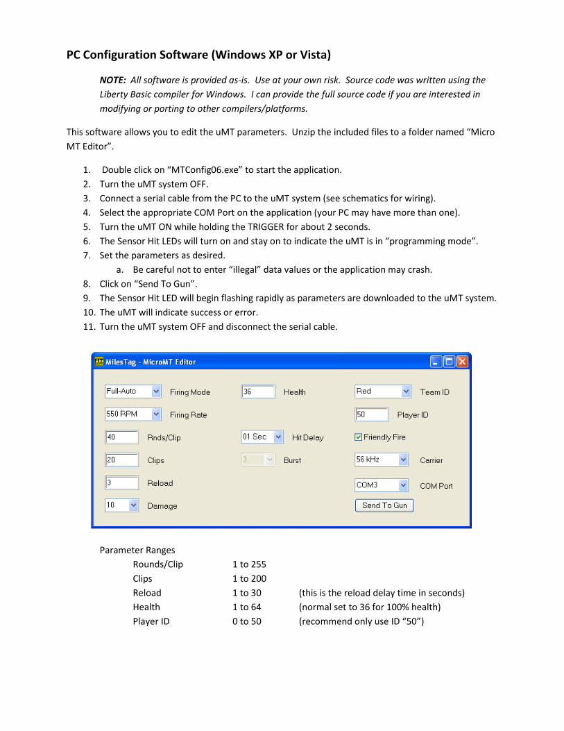
PC Configuration Software (Windows XP or Vista)
NOTE: All software is provided as-is. Use at your own risk. Source code was written using the
Liberty Basic compiler for Windows. I can provide the full source code if you are interested in
modifying or porting to other compilers/platforms.
This software allows you to edit the uMT parameters. Unzip the included files to a folder named “Micro
MT Editor”.
1. Double click on “MTConfig06.exe” to start the application.
2. Turn the uMT system OFF.
3. Connect a serial cable from the PC to the uMT system (see schematics for wiring).
4. Select the appropriate COM Port on the application (your PC may have more than one).
5. Turn the uMT ON while holding the TRIGGER for about 2 seconds.
6. The Sensor Hit LEDs will turn on and stay on to indicate the uMT is in “programming mode”.
7. Set the parameters as desired.
a. Be careful not to enter “illegal” data values or the application may crash.
8. Click on “Send To Gun”.
9. The Sensor Hit LED will begin flashing rapidly as parameters are downloaded to the uMT system.
10. The uMT will indicate success or error.
11. Turn the uMT system OFF and disconnect the serial cable.
Parameter Ranges
Rounds/Clip 1 to 255
Clips 1 to 200
Reload 1 to 30 (this is the reload delay time in seconds)
Health 1 to 64 (normal set to 36 for 100% health)
Player ID 0 to 50 (recommend only use ID “50”)

uMT Sound Programmer (Windows XP or Vista)
NOTE: All software is provided as-is. Use at your own risk. Source code was written using the
Liberty Basic compiler for Windows. I can provide the full source code if you are interested in
modifying or porting to other compilers/platforms.
The Sound Programmer utility allows you to reprogram the uMT with your own custom sound effects.
This software is provided free of charge and as-is. Use it at your own risk. I have no problems on a
desktop PC running Vista Home, a desktop PC running Windows XP Pro and a Laptop running Windows
XP.
I have received at least one report of issues running this software under Windows 7. Sound 01
did not record correctly, and this caused problems in sound retriggering on Full-Auto.
To customize the uMT module with your own sound files (.wav), simply place the new files in the same
folder as the Sound Programmer application. The new files must be renamed exactly as the original
files, so you should back up the original files before replacing them.
NOTE 1: The overall sound volume and quality are significantly affected by speaker selection.
NOTE 2: There is a maximum length allotted for each sound effect. Make sure any custom sounds do not exceed
the maximum length or the end of the sound will be cut off:
NOTE 3: If you are creating your own sound effects, use a sound editor to normalize the volume of all sound effect
files. Also trim any silence or unwanted artifacts from the start and end of each sound to prevent delays during
playback.
SOUND NAME FUNCTION FILE NAME MAX LENGTH
Sound 01 Shot Gun Firing 01_shot_umt.wav 1.5 second
Sound 02 Empty Hammer Click 02_empty_umt.wav 1 second
Sound 03 Clip Out Start Reload 03_clip_umt.wav 1 seconds
Sound 04 Action End Reload 04_action_umt.wav 1.5 seconds
Sound 05 Near Miss Near Miss 05_miss_umt.wav 1.5 seconds
Sound 06 Damage Hit 06_hit_umt.wav 2 seconds
Sound 07 Kill Kill 07_kill_umt.wav 3 seconds
Sound 08 Power Up Power Up 08_power_umt.wav 4 seconds
Sound 09 Beep Okay 09_beep_umt.wav 1 seconds
Sound 10 Buzz Error 10_buzz_umt.wav 1 seconds
Sound 11 Medic Receive Health 11_medic_umt.wav 1.5 seconds
Sound 12 Game Over Game Over 12_gameover_umt.wav 1.5 seconds
Sound 13 Critical Low Health 13_critical_umt.wav 1.5 seconds
Sound 14 Beep 2 Beep 2 14_beep2_umt.wav 1.5 seconds
Sound 15 Disarm No Ammo 15_disarm_umt.wav 1.5 seconds
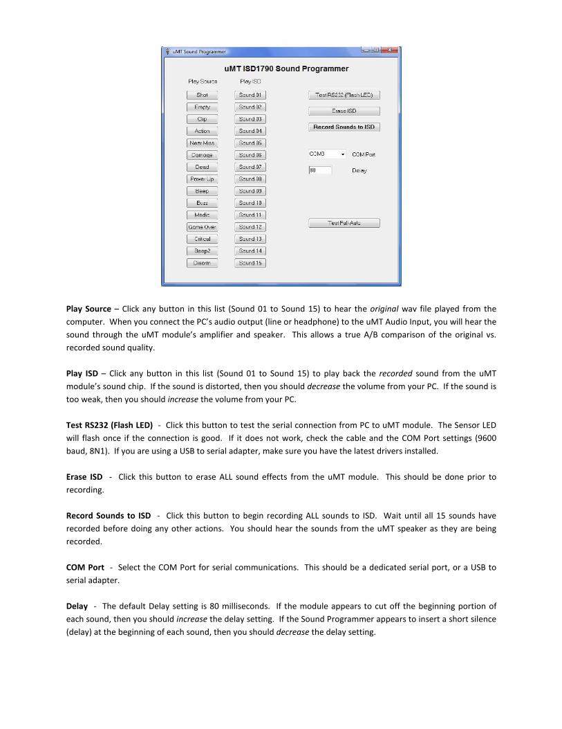
Play Source – Click any button in this list (Sound 01 to Sound 15) to hear the original wav file played from the
computer. When you connect the PC’s audio output (line or headphone) to the uMT Audio Input, you will hear the
sound through the uMT module’s amplifier and speaker. This allows a true A/B comparison of the original vs.
recorded sound quality.
Play ISD – Click any button in this list (Sound 01 to Sound 15) to play back the recorded sound from the uMT
module’s sound chip. If the sound is distorted, then you should decrease the volume from your PC. If the sound is
too weak, then you should increase the volume from your PC.
Test RS232 (Flash LED) - Click this button to test the serial connection from PC to uMT module. The Sensor LED
will flash once if the connection is good. If it does not work, check the cable and the COM Port settings (9600
baud, 8N1). If you are using a USB to serial adapter, make sure you have the latest drivers installed.
Erase ISD - Click this button to erase ALL sound effects from the uMT module. This should be done prior to
recording.
Record Sounds to ISD - Click this button to begin recording ALL sounds to ISD. Wait until all 15 sounds have
recorded before doing any other actions. You should hear the sounds from the uMT speaker as they are being
recorded.
COM Port - Select the COM Port for serial communications. This should be a dedicated serial port, or a USB to
serial adapter.
Delay - The default Delay setting is 80 milliseconds. If the module appears to cut off the beginning portion of
each sound, then you should increase the delay setting. If the Sound Programmer appears to insert a short silence
(delay) at the beginning of each sound, then you should decrease the delay setting.
Test Full-Auto - Click this button to play “Sound 01” (firing sound) in a rapid-fire sequence. This allows you to
hear what the uMT will sound like when firing in Full-Auto mode. If the firing sound is inaudible during rapid fire,
or it is “stuttering”, you may want to re-record the sounds and/or adjust the DELAY value.
RECORDER OPERATION
NOTE: A special RECORD CHIP is used for programming sounds into the uMT. This is a
PIC16F684 with firmware for interfacing with the Recording Software application. The firmware
for the RECORD CHIP is available for download.
1. Make sure the uMT module is fully connected and Power is OFF.
2. Install the RECORD CHIP (PIC16F684 with Recording Firmware) to the uMT module.
a. The Recorder Firmware is required for recording sounds.
b. The recorder will NOT work with the uMT Firmware.
3. Connect audio cable from PC to uMT module.
4. Start Sound Programmer Application.
5. Select COM Port.
6. Turn uMT module ON, watch for Sensor LED to flash.
7. Connect Serial cable from PC to uMT module.
8. Click on the Test RS232 button, watch for Sensor LED to flash.
9. If Sensor LED did not flash, change COM Port.
10. Click on Erase ISD, watch for Sensor LED to flash.
11. Click on Record Sounds to ISD, Sensor LED will light during recording.
12. After recording completes, use the Play ISD buttons to review sounds.
13. Use the Test Full Auto to see if Sound01 is able to retrigger for rapid fire.
14. If there are any problems, just click “Erase ISD” and record again.
15. It is not unusual to require 2-3 attempts to get a good recording.
16. If recording is okay, turn off uMT power.
17. Disconnect Serial Cable and Audio Cable.
18. Remove the RECOPRD CHIP and install the PIC16F684 with uMT Firmware.
19. Turn the uMT ON and test operation.
TIPS & RESOURCES
∆ Use a good quality ESD-safe soldering iron and solder intended for electronics PCB assembly.
∆ Use proper ESD handling procedures for sensitive components.
∆ Do not overheat components or connections during soldering.
∆ Use stranded core ‘hook-up’ wire for off-board connections. Do NOT use solid core wire.
Battery wiring: 22ga
IR LED wiring: 22ga
Button wiring: 24-26ga
All other: 24ga
Telephone extension wire (4 conductor stranded-core) works well for sensors.
Online Help Forum: www.LaserForums.com (go to the MilesTag sub-forum)
Firmware, Parts, Info: www.LaserTagParts.com