Embed Size (px)
Citation preview

DESCRIPTIONAll MICRO SWITCH™ 14CE Series miniature precision switches incorporate fluorocarbon diaphragm sealing to provide reliable protection, meeting IP65, IP66, IP67, and IP68, as well as NEMA 1, 2, 3, 3R, 4, 6, 6P, and 13 requirements. Versions with a boot seal also meet NEMA 12 requirements (dust, falling dirt, liquid media with solid contaminates). The cable or connector and basic switch terminals are encapsulated in an epoxy sealant, offering excellent resistance in harsh environments. For low temperature applications (down to -40 °C, -40 °F), CE Series switches can be supplied with low temperature seals and lubricant.
The CE Series switches are rugged and versatile switches which can be applied indoors in many harsh factory floor applications, as well as on outdoor equipment in extreme temperatures. A full range of actuators are available, including pin plungers, roller plungers, side rotary, multi-directional wire, and manually operated. The switches are also available with the industry standard, M12 micro-change 4-pin connector. MICRO SWITCH 14CE products meet European and Asian CE requirements.
VALUE TO CUSTOMERS• Big performance in a small package• Delivers consistent performance in many demanding
environments where petroleum, synthetic, or water based fluids are present
• Product variation within defined nomenclature
FEATURES• Rugged, miniature construction means minimal real estate
on equipment• NEMA 1, 2, 3, 3R, 4, 6, 6P, 12 (boot seal), 13, and
IP65/66/67/68 environmental sealing• Pre-leaded (Cenelec cable) or supplied with a M12 four-pin
connector• Wide selection of actuators and cable length variations with
side and bottom exit cable/connector options • 25 mm mounting centers engineered with a MICRO SWITCH
SM switch for consistent, precise actuation• Well suited for up to 10 million actuation cycles (Up to 5
million actuation cycles for wobble actuators)• Gang mounting capability to provide a multi-plunger limit
switch• Low temperature variants available for indoor and outdoor
applications• CE approvals for European and Asian use
POTENTIAL APPLICATIONS• Machine tools• Off-road equipment• Material handling• Access and mobility solutions• Textile machinery• Robotics• Packaging equipment• Commercial appliances• Print trade machinery• Agricultural machinery DIFFERENTIATION• Diaphragm seal between the actuator and the switch cavity
for high performance sealing• CE Series incorporates MICRO SWITCH SM basic switch for
consistent, precise actuation• Side exit termination for space constraints
PORTFOLIOHoneywell’s MICRO SWITCH 14CE limit switch is part of a comprehensive offering of rugged and reliable limit switches. To view the entire product portfolio, click here.
Sensing and Internet of Things
Datasheet
MICRO SWITCH Miniature Precision Limit Switches14CE Series
002387Issue 5

2 sensing.honeywell.com
MICRO SWITCH Miniature Precision Limit Switches, 14CE Series
Table 1. Specifications
Characteristic Parameter
Description compact enclosed limit switch
Actuators
• Top pin plunger (14CE1-) • Parallel roller plunger (14CE2-) • Cross roller plunger (14CE3-) • Side rotary (14CE16-)• Top pin plunger with boot seal (14CE18-) • Top adjustable plunger (14CE19-)• Wobble (14CE20-) • Manually operated (14CE22-)• Top pin plunger, panel mount (14CE27-) • Ball bearing plunger (14CE66-)• Top roller plunger, parallel and panel mount (14CE28-) • Top roller plunger, perpendicular, panel mount (14CE29-)• Top roller plunger, parallel and boot sealed (14CE31-)• Top roller plunger, perpendicular, boot seal (14CE55-)
TerminationsHarmonized Cenelec PVC sheathed 4 x 0,75 mm2 (18 AWG) cableConnector (dc), 4-pin male, M12 thread (-Q)Connector (ac), 4-pin male, 1/2 in x 20 thread (-Q1)
Switching options SPDT, snap action contacts (1NC/1NO) Form C
SealingIP65, IP66, IP67, IP68*NEMA 1, 2, 3, 3R, 4, 6, 6P, 12 (boot seal), 13
Operating temperature 0 °C to 70 °C [32 °F to 158 °F]; optional -40 °C to 70 °C [-40 °F to 158 °F]
Mechanical life up to 10 million; up to 5 million (wobble actuators) cycles
Thermal current 1 A, 3 A, 5 A (depending upon model)
Rated insulation voltage (Ui) 250 V
Rated impulse withstand voltage (Uimp)
1.5 kV
Short circuit protection device (SCPD) Quick blow fuse suitable for rated current of switch
Pollution degree 3
Min. actuation speed 0.003 m/s
Max. actuation speed 0.1 m/s
Max. actuation frequency ac – 200 Hz; dc – 20 Hz
Shock 50 g – IEC 60068-2-27
Vibration 10 g – IEC 60068-2-6
Approvals CE
Conforming to standards EN 60947-5-1; AC-14 D300, DC-13 R300
*IP68 sealing submerged in one meter of water for 24 hours
Table 2. Electrical Ratings (in amperes)
Model example Contacts Rating14CE_-_ Silver contacts A14CE_-_G Gold contacts B14CE_-Q, -AQ, -AQ1 Silver contacts C with 4-pin connector
Rating code Make Break
A
240 Vac, ind. 1.2 0.2
240 Vac, res. 5 5
28 Vdc, res. 3 3
28 Vdc, ind. 3 3
5 A, 1/10 HP, 125 Vac or 250 Vac – –
B5-25 mA5-50 Vdc
– –
C 3 A, 125 Vac or 250 Vac – –
Sensing and Internet of Things 3
MICRO SWITCH Miniature Precision Limit Switches, 14CE Series
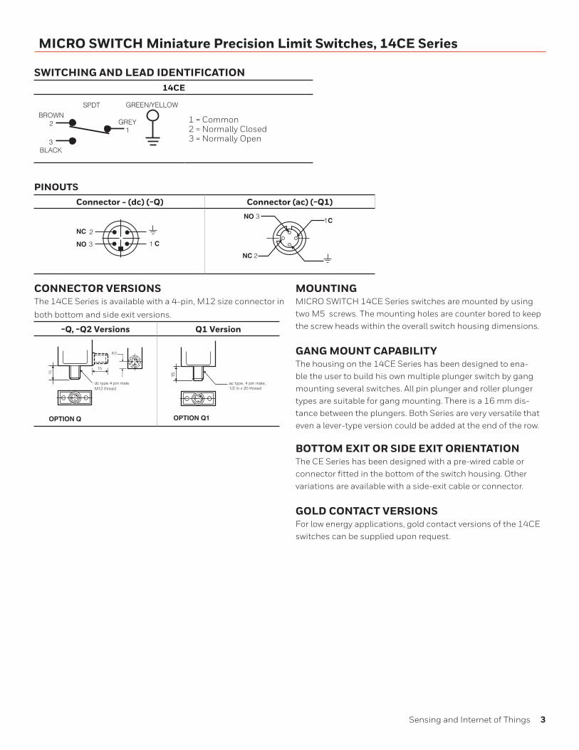
SWITCHING AND LEAD IDENTIFICATION14CE
GREEN/YELLOW
GREY1
BROWN2
3BLACK
SPDT
1 = Common2 = Normally Closed3 = Normally Open
PINOUTSConnector - (dc) (-Q) Connector (ac) (-Q1)
13
2
13NO
NC
C
NO
NC
C
2
13
2
13NO
NC
C
NO
NC
C
2
CONNECTOR VERSIONSThe 14CE Series is available with a 4-pin, M12 size connector in
both bottom and side exit versions.
-Q, -Q2 Versions Q1 Version
8.0
15
OPTION Q
dc type 4 pin maleM12 thread
15
15
OPTION Q1
ac type, 4 pin male,1/2 in x 20 thread
MOUNTINGMICRO SWITCH 14CE Series switches are mounted by using two M5 screws. The mounting holes are counter bored to keep the screw heads within the overall switch housing dimensions.
GANG MOUNT CAPABILITYThe housing on the 14CE Series has been designed to ena-ble the user to build his own multiple plunger switch by gang mounting several switches. All pin plunger and roller plunger types are suitable for gang mounting. There is a 16 mm dis-tance between the plungers. Both Series are very versatile that even a lever-type version could be added at the end of the row.
BOTTOM EXIT OR SIDE EXIT ORIENTATIONThe CE Series has been designed with a pre-wired cable or connector fitted in the bottom of the switch housing. Other variations are available with a side-exit cable or connector.
GOLD CONTACT VERSIONSFor low energy applications, gold contact versions of the 14CE switches can be supplied upon request.

4 sensing.honeywell.com
MICRO SWITCH Miniature Precision Limit Switches, 14CE Series
GENERAL DIMENSIONS • ALL SWITCHES
PRODUCT NOMENCLATURE
3
16
2
1 Top pinplunger
Top rollerplunger, parallel
Top rollerplunger, perp.
Siderotary
14CE
Switch Type
16
Actuator Type Options1,2
D
B
A Side entry
Elongatedmounting holes
Halogen-freecable
MICRO SWITCH™ 914CE Miniature Limit SwitchProduct Nomenclature
19
18 Top pin plungerw/ boot seal
Top adjustablepin plunger
29
31
28
27 Top pin plunger,panel mount
Top roller plunger, parallelpanel mount
Top rollerplunger, perp.panel mount
Top roller plunger, parallelboot seal
66
55Top rollerplunger, perp.boot seal
Top ball bearingplunger
14CE SeriesCompact Precision
Limit Switch
–
3
2
1 1 meter
2 meters
3 meters
4 4 meters
5 5 meters
3
Cable Length*
20 Coilwobble
22 Manually oper.nylon button
HHigh temp.,150 °C
Connectors*(micro type)
Q1
Qdc typesingle keyway4-pin male, M12ac typetwo keyways4-pin male, 1/2-20
Bottom exit isstandard.
NOTE: not all combinations of model codes are available.Please contact your Honeywell provider/representative for assistance.
1More than one option may be permissible.
* Select “Cable Length” or “Connectors”
2OPTION K to be discontinued. Replaced with fluorocarbon diaphragm seal, standard switch.2OPTION KV to be discontinued. Replaced with fluorocarbon diaphragm seal, standard switch.
P
G Goldcontacts
Topmounting
L1Low temp.-40 °C, cablenot for flexing
V
LLow temp.,-40 °C switch and cable
Viton® seals/gasket(side rotary and booted sealed plungers only)
44 mm max.[1.73 in max.]
25 mm[0.98 in]
16 mm max.[0.63 in max.]
40 mm max.[1.57 in max.]
Max. free length
Operating position (OP)
3 mm min. [0.12 in min.]
8,0 mm[0.31 in]
8,0 mm[0.32 in]
7,6 mm[0.30 in]
Pretravel (PT)
Overtravel (OT)
CABLE VERSION
TYPE Q
TYPEQ1
M12thread
1/2 x 20 UNFthread
Two (2) holes Ø 5.1 mm [Ø 0.2 in] dia. c/bore10,2 mm dia x 6 mm deep [0.40 in dia x 0.24 in deep](Both sides - option “A” only)
15 mm[0.59 in]

Sensing and Internet of Things 5
MICRO SWITCH Miniature Precision Limit Switches, 14CE Series
PRODUCT SPECIFICATIONS AND LISTINGSContact your Honeywell rep or distributor for additional listings
14CE1 • Pin Plunger14CE27 • Pin Plunger Panel Mount
Con-tacts
Elec Rating
Cable/Connector
Position
Free Posi-tion (FP)
Operating Position
(OP)Options Listing
FP
PT
OP
OT
M10 X 1 METRIC THREAD12 mm [0.49 in]
THREADED LENGTH
GRY-BRN
��
GRY-BLK
GRY-BRNGRY-BLK
17,5 12,715,7
15,8
Pretravel • 1,8 mm [0.071 in]
Diff. travel • 0,1 mm [0.004 in]
Overtravel • 3,0 mm [0.118 in]
Oper. force • 11,8 N [2.65 lb]
GRY-BRN
��
GRY-BLK
GRY-BRNGRY-BLK
31,1 26,329,3
29,4
Silver A Bottom17,5 mm [0.69 in]
15,7 mm[0.62 in]
– 14CE1-1
Gold B Bottom17,5 mm [0.69 in]
15,7 mm[0.62 in]
Gold-plated contacts
14CE1-1G
Silver A Side17,5 mm [0.69 in]
15,7 mm[0.62 in]
Side exit cable 14CE1-1A
Silver C Bottom17,5 mm [0.69 in]
15,7 mm[0.62 in]
dc-typeconnector
14CE1-Q
Silver A Bottom31,1 mm [1.23 in]
29,3 mm[1.15 in]
Panel mount 14CE27-1
14CE18 • Boot Sealed Pin Plunger Con-tacts
Elec Rating
Cable/Connector
Position
Free Posi-tion (FP)
Operating Position
(OP)Options Listing
FPOP
OTPT
BOOT SEALØ7,0 mm[Ø0.28 in]
GRY-BRN
��
GRY-BLK
GRY-BRNGRY-BLK
26,7 21,924,9
25
Pretravel • 1,8 mm [0.071 in]
Diff. travel • 0,1 mm [0.004 in]
Overtravel • 3,0 mm [0.118 in]
Oper. force • 22,5 N [5.06 lb]
Silver A Bottom26,7 mm[1.05 in]
24,9 mm[0.98 in]
– 14CE18-1
Silver A Side26,7 mm[1.05 in]
24,9 mm[0.98 in]
Side exit cable 14CE18-1A
Silver C Bottom26,7 mm[1.05 in]
24,9 mm[0.98 in]
dc-typeconnector
14CE18-Q
14CE66 • Ball Bearing Plunger Con-tacts
Elec Rating
Cable/Connector
Position
Free Posi-tion (FP)
Operating Position
(OP)Options Listing
FPOP
OT PT
7,9 mm [0.31 in] DIA BALL BEARING
GRY-BRN
��
GRY-BLK
GRY-BRNGRY-BLK
26,2 21,424,4
24,5
Pretravel • 1,8 mm [0.071 in]
Diff. travel • 0,1 mm [0.004 in]
Overtravel • 3,0 mm [0.118 in]
Oper. force • 11,8 N [2.65 lb]
Silver A Bottom26,2 mm[1.03 in]
24,4 mm[0.96 in]
– 14CE66-1
Silver A Side26,2 mm[1.03 in]
24,4 mm[0.96 in]
Side exit cable 14CE66-1A
Ø10,0 mm[Ø0.39 in]
FP
OP
OT PT

6 sensing.honeywell.com
MICRO SWITCH Miniature Precision Limit Switches, 14CE Series
14CE2 • Roller Plunger14CE28 • Roller Plunger Panel Mount
Con-tacts
Elec Rating
Cable/Connector
Position
Free Posi-tion (FP)
Operating Position
(OP)Options Listing
FP
PT
OP
OT
M14 X 1 THREAD
ROLLERØ 12,4 mm x 4,7 mm[Ø 0.48 in x 0.020 in]
GRY-BRN
��
GRY-BLK
GRY-BRNGRY-BLK
30,3 25,528,5
28,6
Pretravel • 1,8 mm [0.071 in]
Diff. travel • 0,1 mm [0.004 in]
Overtravel • 3,0 mm [0.118 in]
Oper. force • 11,8 N [2.65 lb]
GRY-BRN
��
GRY-BLK
GRY-BRNGRY-BLK
44,3 39,542,5
42,6
Silver A Bottom30,3 mm[1.19 in]
28,5 mm[1.12 in]
– 14CE2-1
Gold B Bottom30,3 mm[1.19 in]
28,5 mm[1.12 in]
Gold-plated contacts
14CE2-1G
Silver C Bottom30,3 mm[1.19 in]
28,5 mm[1.12 in]
dc-typeconnector
14CE2-Q
Silver A Side30,3 mm[1.19 in]
28,5 mm[1.12 in]
Side exit cable 14CE2-1A
Silver A Bottom44,3 mm[1.75 in]
42,5 mm[1.67 in]
Panel mount, 2 m cable
14CE28-2
14CE31 • Boot Sealed Roller Plunger Con-tacts
Elec Rating
Cable/Connector
Position
Free Posi-tion (FP)
Operating Position
(OP)Options Listing
FPOP
OTPT
BOOT SEAL
ROLLERØ 12,4 mm x 4,7 mmØ 0.48 in x 0.020 in] GRY-BRN
��
GRY-BLK
GRY-BRNGRY-BLK
36,2 31,434,4
34,5
Pretravel • 1,8 mm [0.071 in]
Diff. travel • 0,1 mm [0.004 in]
Overtravel • 3,0 mm [0.118 in]
Oper. force • 17,5 N [3.93 lb]
Silver A Bottom36,2 mm[1.43 in]
34,4 mm[1.36 in]
– 14CE31-1
Silver A Bottom36,2 mm[1.43 in]
34,4 mm[1.36 in]
Fluorocarbon seals, 6 m cable
14CE31-6V
14CE3 • Cross Roller Plunger Con-tacts
Elec Rating
Cable/Connector
Position
Free Posi-tion (FP)
Operating Position
(OP)Options Listing
GRY-BRN
��
GRY-BLK
GRY-BRNGRY-BLK
30,3 25,528,5
28,6
Pretravel • 1,8 mm [0.071 in]
Diff. travel • 0,1 mm [0.004 in]
Overtravel • 3,0 mm [0.118 in]
Oper. force • 11,8 N [2.65 lb]
Silver A Bottom30,3 mm[1.19 in]
28,5 mm[1.12 in]
– 14CE3-1
Silver A Side30,3 mm[1.19 in]
28,5 mm[1.12 in]
3 m of cable, side exit
14CE3-3A
Silver C Bottom30,3 mm[1.19 in]
28,5 mm[1.12 in]
dc-typeconnector
14CE3-Q
FPOP
OT
PTØ12,4 mm[Ø0.49 in]
Ø12,4 mm[Ø0.49 in]
FPOP
OTPT

Sensing and Internet of Things 7
MICRO SWITCH Miniature Precision Limit Switches, 14CE Series
14CE55 • Boot Sealed Cross Roller Plunger
Con-tacts
Elec Rating
Cable/Connector
Position
Free Posi-tion (FP)
Operating Position
(OP)Options Listing
FPOP
OTPT
BOOT SEAL
ROLLERØ 12,4 mm x 4,7 mmØ 0.48 in x 0.020 in]
GRY-BRN
��
GRY-BLK
GRY-BRNGRY-BLK
36,2 31,434,4
34,5
Pretravel • 1,8 mm [0.071 in]
Diff. travel • 0,1 mm [0.004 in]
Overtravel • 3,0 mm [0.118 in]
Oper. force • 17,5 N [3.93 lb]
Silver A Bottom36,2 mm[1.43 in]
34,4 mm[1.36 in]
3 meters of cable 14CE55-3
14CE16 • Side Rotary Con-tacts
Elec Rating
Cable/Connector
Position
Free Posi-tion (FP)
Operating Position
(OP)Options Listing
PT
OT
PT
OT
18,9 mm[0.74 in]Actuator shaft
Ø7,32 mm[Ø0.288 in]
DTDT
FPGRY-BRN
��
GRY-BLK
GRY-BRNGRY-BLK
0° 70°30°
27°
Pretravel • 30°
Diff. travel • 3°
Overtravel • 40°
Oper. force • 0,34 Nm [3 in-lb]
Silver A Bottom 0° 30° – 14CE16-11
Gold B Bottom 0° 30°Gold-plated
contacts, 3 meters of cable
14CE16-3G1
Silver C Bottom 0° 30°dc-type
connector14CE16-Q1
14CE20 • Random Motion Wire Actuator
Con-tacts
Elec Rating
Cable/Connector
Position
Free Posi-tion (FP)
Operating Position
(OP)Options Listing
OPALL DIRECTIONSEXCEPT DIRECT
PULL
335,0 mm max.[13,98 mm max.]
Ø1.8 mm[Ø0.07 in]
GRY-BRNGRY-BLK
GRY-BRNGRY-BLK
0 28 max.
Oper. position • 28 mm [1.10 in] max.
Oper. force • 0,55 N [0.12 lb] max.
Silver A Bottom –28 mm
[1.10 in] max.
– 14CE20-1
1 Switch operates on clockwise and counterclockwise rotation of lever shaft
Note: Most part numbers are shown with 1 meter of cable. The -X indicates the number of meters of cable provided: 2-meters, 3-meters, 4-meters, and 5-meters. Custom lengths are also available.
8 sensing.honeywell.com
MICRO SWITCH Miniature Precision Limit Switches, 14CE Series
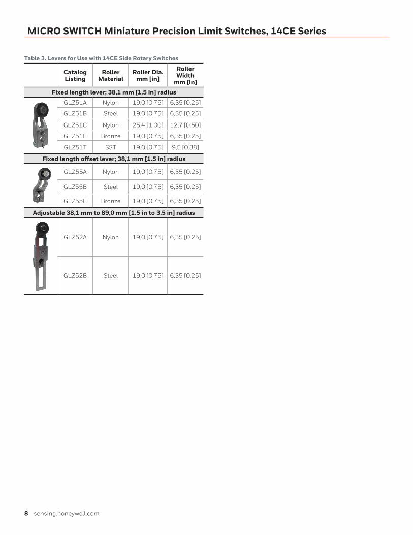
Table 3. Levers for Use with 14CE Side Rotary Switches
Catalog Listing
Roller Material
Roller Dia. mm [in]
Roller Width
mm [in]
Fixed length lever; 38,1 mm [1.5 in] radius
GLZ51A Nylon 19,0 [0.75] 6,35 [0.25]
GLZ51B Steel 19,0 [0.75] 6,35 [0.25]
GLZ51C Nylon 25,4 [1.00] 12,7 [0.50]
GLZ51E Bronze 19,0 [0.75] 6,35 [0.25]
GLZ51T SST 19,0 [0.75] 9,5 [0.38]
Fixed length offset lever; 38,1 mm [1.5 in] radius
GLZ55A Nylon 19,0 [0.75] 6,35 [0.25]
GLZ55B Steel 19,0 [0.75] 6,35 [0.25]
GLZ55E Bronze 19,0 [0.75] 6,35 [0.25]
Adjustable 38,1 mm to 89,0 mm [1.5 in to 3.5 in] radius
GLZ52A Nylon 19,0 [0.75] 6,35 [0.25]
GLZ52B Steel 19,0 [0.75] 6,35 [0.25]

ADDITIONAL MATERIALS• Product installation instructions
• Product range guide
• Product nomenclature tree
• Product application-specific information
– Limit and enclosed switches application information
– Limit and enclosed switches operating characteristics
– Limit and enclosed switches reference standards
– Limit and enclosed switches typical applications
– Product flyer: CE Family Miniature Limit Switches
m WARNINGPERSONAL INJURYDO NOT USE these products as safety or emergency stop devices or in any other application where failure of the product could result in personal injury.
Failure to comply with these instructions could result in death or serious injury.
m WARNINGMISUSE OF DOCUMENTATION• The information presented in this product sheet is for
reference only. Do not use this document as a product installation guide.
• Complete installation, operation, and maintenance information is provided in the instructions supplied with each product.
Failure to comply with these instructions could result in death or serious injury.
Warranty/RemedyHoneywell warrants goods of its manufacture as being free of defective materials and faulty workmanship during the appli-cable warranty period. Honeywell’s standard product warranty applies unless agreed to otherwise by Honeywell in writing; please refer to your order acknowledgment or consult your local sales office for specific warranty details. If warranted goods are returned to Honeywell during the period of coverage, Honeywell will repair or replace, at its option, without charge those items that Honeywell, in its sole discretion, finds defec-tive. The foregoing is buyer’s sole remedy and is in lieu of all other warranties, expressed or implied, including those of merchantability and fitness for a particular purpose. In no event shall Honeywell be liable for consequential, special, or indirect damages.
While Honeywell may provide application assistance personally, through our literature and the Honeywell web site, it is buyer’s sole responsibility to determine the suitability of the product in the application.
Specifications may change without notice. The information we supply is believed to be accurate and reliable as of this writing. However, Honeywell assumes no responsibility for its use.
Viton® is a registered trademark of DuPont Performance Elastomers L.L.C.
002387-5-EN | 5 | 05/19© 2019 Honeywell International Inc. All rights reserved.
For more informationHoneywell Sensing and Internet of
Things services its customers through a
worldwide network of sales offices and
distributors. For application assistance,
current specifications, pricing or the
nearest Authorized Distributor, visit
sensing.honeywell.com or call:
Asia Pacific +65 6355-2828
Europe +44 1698 481481
USA/Canada +1-800-537-6945
Honeywell Sensing and Internet of Things9680 Old Bailes Road
Fort Mill, SC 29707
www. honeywell.com