Embed Size (px)
Citation preview
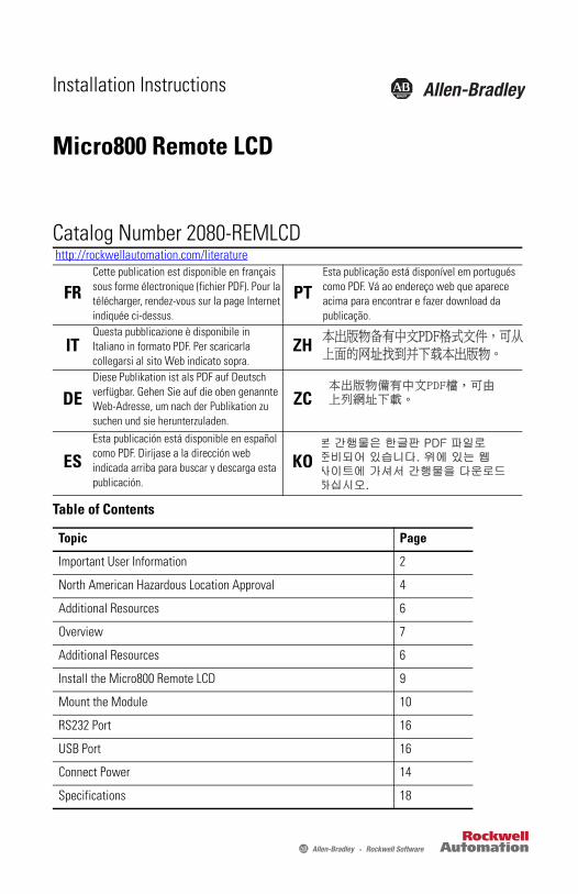
Installation Instructions
Micro800 Remote LCD
Catalog Number 2080-REMLCD
http://rockwellautomation.com/literature
FRCette publication est disponible en français sous forme électronique (fichier PDF). Pour la télécharger, rendez-vous sur la page Internet indiquée ci-dessus.
PTEsta publicação está disponível em portugués como PDF. Vá ao endereço web que aparece acima para encontrar e fazer download da publicação.
ITQuesta pubblicazione è disponibile in Italiano in formato PDF. Per scaricarla collegarsi al sito Web indicato sopra.
ZH
DEDiese Publikation ist als PDF auf Deutsch verfügbar. Gehen Sie auf die oben genannte Web-Adresse, um nach der Publikation zu suchen und sie herunterzuladen.
ZC
ESEsta publicación está disponible en español como PDF. Diríjase a la dirección web indicada arriba para buscar y descarga esta publicación.
KO
Table of Contents
Topic Page
Important User Information 2
North American Hazardous Location Approval 4
Additional Resources 6
Overview 7
Additional Resources 6
Install the Micro800 Remote LCD 9
Mount the Module 10
RS232 Port 16
USB Port 16
Connect Power 14
Specifications 18

2 Micro800 Remote LCD
Important User Information Solid state equipment has operational characteristics differing from those of electromechanical equipment. Safety Guidelines for the Application, Installation and Maintenance of Solid State Controls (Publication SGI-1.1 available from your local Rockwell Automation sales office or online at http://rockwellautomation.com/literature) describes some important differences between solid state equipment and hard-wired electromechanical devices. Because of this difference, and also because of the wide variety of uses for solid state equipment, all persons responsible for applying this equipment must satisfy themselves that each intended application of this equipment is acceptable.In no event will Rockwell Automation, Inc. be responsible or liable for indirect or consequential damages resulting from the use or application of this equipment.The examples and diagrams in this manual are included solely for illustrative purposes. Because of the many variables and requirements associated with any particular installation, Rockwell Automation, Inc. cannot assume responsibility or liability for actual use based on the examples and diagrams.No patent liability is assumed by Rockwell Automation, Inc. with respect to use of information, circuits, equipment, or software described in this manual.Reproduction of the contents of this manual, in whole or in part, without written permission of Rockwell Automation, Inc., is prohibited.Throughout this manual, when necessary, we use notes to make you aware of safety considerations.
WARNING: Identifies information about practices or circumstances that can cause an explosion in a hazardous environment, which may lead to personal injury or death, property damage, or economic loss.
ATTENTION: Identifies information about practices or circumstances that can lead to personal injury or death, property damage, or economic loss. Attentions help you identify a hazard, avoid a hazard and recognize the consequences.
SHOCK HAZARD: Labels may be on or inside the equipment (for example, drive or motor) to alert people that dangerous voltage may be present.
BURN HAZARD: Labels may be on or inside the equipment (for example, drive or motor) to alert people that surfaces may reach dangerous temperatures.
IMPORTANT IMPORTANT: Identifies information that is critical for successful application and understanding of the product.
Rockwell Automation Publication 2080-IN010B-EN-P – May 2015

Micro800 Remote LCD 3
Environment and Enclosure
Prevent Electrostatic Discharge
ATTENTION: This equipment is intended for use in a Pollution Degree 2 industrial environment, in overvoltage Category II applications (as defined in IEC 60664-1), at altitudes up to 2000 m (6562 ft) without derating.
This equipment is not intended for use in residential environments and may not provide adequate protection to radio communication services in such environments.
This equipment is supplied as open-type equipment. It must be mounted within an enclosure that is suitably designed for those specific environmental conditions that will be present and appropriately designed to prevent personal injury resulting from accessibility to live parts. The enclosure must have suitable flame-retardant properties to prevent or minimize the spread of flame, complying with a flame spread rating of 5VA or be approved for the application if nonmetallic. The interior of the enclosure must be accessible only by the use of a tool. Subsequent sections of this publication may contain additional information regarding specific enclosure type ratings that are required to comply with certain product safety certifications.
In addition to this publication, see:
• Industrial Automation Wiring and Grounding Guidelines, Rockwell Automation publication 1770-4.1, for additional installation requirements.
• NEMA Standard 250 and IEC 60529, as applicable, for explanations of the degrees of protection provided by different types of enclosure.
ATTENTION: This equipment is sensitive to electrostatic discharge, which can cause internal damage and affect normal operation. Follow these guidelines when you handle this equipment:
• Touch a grounded object to discharge potential static.• Wear an approved grounding wriststrap.• Do not touch connectors or pins on component boards.• Do not touch circuit components inside the equipment.• Use a static-safe workstation, if available.• Store the equipment in appropriate static-safe packaging when not in use.
Rockwell Automation Publication 2080-IN010B-EN-P – May 2015

4 Micro800 Remote LCD
North American Hazardous Location ApprovalThe following modules are North American Hazardous Location approved: 2080-REMLCD.
The following information applies when operating this equipment in hazardous locations:
Informations sur l’utilisation de cet équipement en environnements dangereux:
Products marked "CL I, DIV 2, GP A, B, C, D" are suitable for use in Class I Division 2 Groups A, B, C, D, Hazardous Locations and nonhazardous locations only. Each product is supplied with markings on the rating nameplate indicating the hazardous location temperature code. When combining products within a system, the most adverse temperature code (lowest "T" number) may be used to help determine the overall temperature code of the system. Combinations of equipment in your system are subject to investigation by the local Authority Having Jurisdiction at the time of installation.
Les produits marqués "CL I, DIV 2, GP A, B, C, D" ne conviennent qu'à une utilisation en environnements de Classe I Division 2 Groupes A, B, C, D dangereux et non dangereux. Chaque produit est livré avec des marquages sur sa plaque d'identification qui indiquent le code de température pour les environnements dangereux. Lorsque plusieurs produits sont combinés dans un système, le code de température le plus défavorable (code de température le plus faible) peut être utilisé pour déterminer le code de température global du système. Les combinaisons d'équipements dans le système sont sujettes à inspection par les autorités locales qualifiées au moment de l'installation.
WARNING: EXPLOSION HAZARD• Do not disconnect equipment
unless power has been removed or the area is known to be nonhazardous.
• Do not disconnect connections to this equipment unless power has been removed or the area is known to be nonhazardous. Secure any external connections that mate to this equipment by using screws, sliding latches, threaded connectors, or other means provided with this product.
• Substitution of any component may impair suitability for Class I, Division 2.
• If this product contains batteries, they must only be changed in an area known to be nonhazardous.
WARNING: RISQUE D’EXPLOSION• Couper le courant ou s'assurer
que l'environnement est classé non dangereux avant de débrancher l'équipement.
• Couper le courant ou s'assurer que l'environnement est classé non dangereux avant de débrancher les connecteurs. Fixer tous les connecteurs externes reliés à cet équipement à l'aide de vis, loquets coulissants, connecteurs filetés ou autres moyens fournis avec ce produit.
• La substitution de tout composant peut rendre cet équipement inadapté à une utilisation en environnement de Classe I, Division 2.
• S'assurer que l'environnement est classé non dangereux avant de changer les piles.
Rockwell Automation Publication 2080-IN010B-EN-P – May 2015

Micro800 Remote LCD 5
• Make sure all connectors are securely tightened to properly seal the connections against leaks and maintain IP enclosure type requirements.
• The USB port is intended for temporary local programming purposes only and not intended for permanent connection.
• The USB cable is not to exceed 3.0 m (9.84 ft) and must not contain hubs.
• The RS232 and Power cables are not to exceed 3.0 m (9.84 ft).
• Do not place the module in direct sunlight. Prolonged exposure to sunlight may degrade the LCD.
• The USB cap must be in place to maintain IP65 rating.
• If you connect or disconnect the RS232 cable with power applied to this module or the serial device on the other end of the cable, an electrical arc can occur. This could cause an explosion in hazardous location installations.Be sure that power is removed or the area is nonhazardous before proceeding.
• If you connect or disconnect the communications cable with power applied to this module or any device on the network, an electrical arc can occur. This could cause an explosion in hazardous location installations.Be sure that power is removed or the area is nonhazardous before proceeding.
• When used in a Class I, Division 2, hazardous location, this equipment must be mounted in a suitable enclosure with proper wiring method that complies with the governing electrical codes.
• The USB port is intended for temporary local programming purposes only and not intended for permanent connection. If you connect or disconnect the USB cable with power applied to this module or any device on the USB network, an electrical arc can occur. This could cause an explosion in hazardous location installations.Be sure that power is removed or the area is nonhazardous before proceeding.
• Do not connect directly to line voltage. Line voltage must be supplied by a suitable, approved isolating transformer or power supply having short circuit capacity not exceeding 100V A maximum or equivalent.
• Do not use the USB port in hazardous locations.
Rockwell Automation Publication 2080-IN010B-EN-P – May 2015

6 Micro800 Remote LCD
Additional Resources
If you would like a manual, you can:
• download a free electronic version from the Internet: http://rockwellautomation.com/literature
• purchase a printed manual by contacting your local Allen-Bradley distributor or Rockwell Automation representative
Resource DescriptionMicro820 20-point Programmable Controllers User Manual, publication 2080-UM005
A more detailed description of how to install and use your Micro820 programmable controller.
Micro800 Plug-in Modules and Accessories User Manual, publication 2080-UM004
Installation and wiring descriptions for the different Micro800 plug-in modules and accessories.
Micro820 Programmable Controllers Installation Instructions, publication 2080-IN009
Information on how to install your Micro820 programmable controller.
Micro800 AC Power Supply Installation Instructions, publication 2080-IN001
Information on wiring and installing the optional AC power supply.
Industrial Automation Wiring and Grounding Guidelines, publication 1770-4.1
More information on proper wiring and grounding techniques.
Rockwell Automation Publication 2080-IN010B-EN-P – May 2015

Micro800 Remote LCD 7
OverviewThe Micro800™ Remote LCD is a simple IP65 text display interface that allows configuration of such settings as IP address on the Micro800 controller. It is an accessory to the Micro820 controller.
The remote LCD can be connected to the controller through an RS232 port. It can be mounted through the front panel or on the same DIN rail as the controller.
Micro800 Remote LCD Overview
2080-REMLCD Description
Description Description
1 Logo casing(1)
(1) The module is shipped with the Allen-Bradley sticker label but you can customize the space with your product logo. Dimensions for the logo casing and the sticker label are shown below.
6 DIN rail latch
2 Display screen 7 USB port
3 Function keys 8 RS232 port
4 Arrow keys 9 24V DC power port
5 ESC and OK keys
OK
ESC
F4 F5
F1 F2 F3
F6MENU
3 4 5 6 7
1
6 8
Front Back
9
2
37
5
1
Sticker label
36.70
4.70
Sticker casing
Measurements are in millimeters.
Rockwell Automation Publication 2080-IN010B-EN-P – May 2015

8 Micro800 Remote LCD
Module Dimensions
ATTENTION: The length of RS232 and 24V DC power cable connection to the 2080-REMLCD module must not exceed 3 m (9.84 ft.).
Catalog Number Height (a) Width (b) Depth (c)
2080-REMLCD 97 mm (3.82 in.) 130 (5.11 in.) 35.5 (1.40 in.)
OK
ESC
F4 F5
F1 F2 F3
F6MENU
46258
RS232 and 24V DC power cable connections must not exceed 3 m.
Micro820controller
Micro800REMLCD
Powersupply
OK
ESC
F4 F5
F1 F2 F3
F6MENU
a
b c
Rockwell Automation Publication 2080-IN010B-EN-P – May 2015

Micro800 Remote LCD 9
Parts ListThe Micro800 Remote LCD module ships with these items:
• Allen-Bradley sticker label
• Clamp accessories for panel mounting (4 pcs)
• Product Information (publication 2080-PC002)
Install the Micro800 Remote LCD Before installing the Remote LCD through the front panel, review minimum clearances, panel guidelines, panel cutout dimensions, and product dimensions.
Minimum SpacingMaintain spacing from objects such as enclosure walls, wireways, and adjacent equipment. Allow 50.8 mm (2.0 in.) of space on all sides for adequate ventilation. If optional accessories/modules are attached such as the optional power supply, 2080-PS120-240VAC, make sure that there is 50.8 mm (2.0 in.) of space on all sides after attaching the optional parts.
Plan for adequate space around the module, inside the enclosure, for ventilation and cabling. Consider heat produced by other devices in the enclosure. The ambient temperature around the module must be -20…50 °C (-4…122 °F).
Panel GuidelinesSupporting panels must be at least 16 gauge to provide proper sealing against water and dust and to provide proper support. The panel surface must be flat and free of imperfections to maintain an adequate seal and NEMA/IP Type ratings.
IMPORTANT Most applications require installation in an industrial enclosure to reduce the effects of electrical interference and environmental exposure. Locate your device as far as possible from power lines, load lines, and other sources of electrical noise such as hard-contact switches, relays, and AC motor drives. For more information on proper grounding guidelines, see the Industrial Automation Wiring and Grounding Guidelines, publication 1770-4.1.
TIP The minimum spacing requirements are sufficient for connecting cables and inserting. Plan for additional clearance if using the USB host port on the back of the unit.
Rockwell Automation Publication 2080-IN010B-EN-P – May 2015

10 Micro800 Remote LCD
Panel Cutout DimensionsYou can print the panel cutout template that comes at the end of this installation instructions. Panel cutout dimensions are provided in the next table.
Mount the ModuleThere are two ways to mount the Micro800 Remote LCD, as described in the following sections:
• Mount the Module in a Panel
• Mount the Module on a DIN Rail
Catalog Number Height, Approx., mm (inches) Width, Approx., mm (inches)
2080-REMLCD 88.5 ± 0.5 (3.48 ± 0.02) 121.5 ± 0.5 (4.78 ± 0.02)
ATTENTION: Disconnect all electrical power from the panel before making the panel cutout.
• Make sure the area around the panel cutout is clear.• Take precautions so metal cuttings do not enter any components
already installed in the panel.• Failure to follow these instructions may result in personal injury or
damage to panel components.
WARNING: If you connect or disconnect the RS232 cable with power applied to this module or the RS232 device on the other end of the cable, an electrical arc can occur. This could cause an explosion in hazardous location installations. Be sure that power is removed or the area is nonhazardous before proceeding.
WARNING: When used in a Class I, Division 2, hazardous location, this equipment must be mounted in a suitable enclosure with proper wiring method that complies with the governing electrical codes.
Rockwell Automation Publication 2080-IN010B-EN-P – May 2015

Micro800 Remote LCD 11
Mount the Module in a PanelThe Micro800 Remote LCD installs easily on the front panel. Use the clamp accessories shipped with your module to mount it.
Measurements are in millimeters (inches)
130 (5.11)120.7 (4.75)
130(3.81)
87.7(3.45)
clamps
mounting screw
gasket
Panel thickness: 1…5
35 (max)
Panel
NOTE: The REMLCD module can only be installed through the front panel.
Rockwell Automation Publication 2080-IN010B-EN-P – May 2015

12 Micro800 Remote LCD
Follow these steps to mount the remote LCD through the front panel.
1. Make sure the sealing gasket is properly positioned on the module.This gasket forms a compression type seal. Do not use sealing compounds.
2. Place the module in the panel cutout.
3. Once the unit is placed in the panel, tighten the mounting screws evenly to a torque between 0.5…0.6 Nm (4.42…5.31 lb-in.) to maintain water and dust resistance. Make sure the panel is clean and strong enough to hold the unit.
IMPORTANT The module temperature must be greater than 0 °C (32 °F) during panel installation.
OK
ESCF4 F5
F1 F2 F3
F6MENU USB
OK
ESCF4 F5
F1 F2 F3
F6MENU USB
The module is shipped with the Allen-Bradley logosticker (36.70 x 4.70 mm). You can customize this
space with your product logo.
46251
Top view
Side view
Panel
46252
Clamp accessories
Rockwell Automation Publication 2080-IN010B-EN-P – May 2015

Micro800 Remote LCD 13
Mount the Module on a DIN RailThe module can be mounted using the following DIN rails: 35 x 7.5 mm and 35 x 15 mm (EN 50 022 - 35 x 7.5 and EN 50 022 - 35 x 15).
The module can be mounted on the same DIN rail as the controller.
Before mounting the module on a DIN rail, use a flat-blade screwdriver in the DIN rail latch and pry it downwards until it is in the unlatched position.
1. Hook the top of the DIN rail mounting area of the Micro800 Remote LCD module onto the DIN rail, and then press the bottom until the module snaps onto the DIN rail.
2. Push the DIN rail latch back into the latched position.To remove your module from the DIN rail, make sure you pry the DIN rail latch downwards until it is in the unlatched position and slowly disengage the module from the bottom of the rail.
IMPORTANT Do not push on the LCD display when pushing the terminal into the panel or you may damage the display.
ATTENTION: Follow the instructions to provide a proper seal and to prevent potential damage to the device. Allen-Bradley assumes no responsibility for water or chemical damage to the terminal or other equipment within the enclosure because of improper installation.
OK
ESC
F4 F5
F1 F2 F3
F6
MENU
USB
46253
97 (3.82)
130 (5.12) 35.5 (1.40)
Measurements are in millimeters (inches)
Rockwell Automation Publication 2080-IN010B-EN-P – May 2015

14 Micro800 Remote LCD
Connect PowerThe Micro800 Remote LCD connects to a 24V DC power source. See the Specifications on page 18 for the module power ratings.The internal, nonisolated power supply is protected against reverse polarity of the DC+ and DC connections.
Wire Specifications for the Input Power Terminal BlockThe input power terminal block supports these wire sizes.
Follow these steps to connect power.
1. Verify that the terminal is not connected to a power source.
ATTENTION: Connecting DC+ or DC- source to the functional earth terminal may damage the device. Miswiring the DC+ source to the DC- input while connected to other equipment through nonisolated ports may cause a ground loop current and damage the device.
WARNING: Use supply wires suitable for 30 °C (86 °F) above surrounding ambient.
WARNING: If you connect or disconnect wiring while the power is on, an electrical arc can occur. This could cause an explosion in hazardous location installations. Be sure that power is removed or the area is nonhazardous before proceeding.
Wire Type Dual-wire gauge(1)
(1) Two-wire maximum per terminal.
Single-wire gauge Terminal Screw Torque
Stranded or solid Cu 90 °C(194 °F)
0.14…0.75 mm2
(26…18 AWG)0.14…1.5 mm2
(26…16 AWG)0.5…0.6 Nm(4.42…5.31 lb-in.)
ATTENTION: Disconnect all power before installing or replacing components. Failure to disconnect power may result in electrical shock or damage to the module.
Rockwell Automation Publication 2080-IN010B-EN-P – May 2015

Micro800 Remote LCD 15
2. Secure the 24V DC power wires.
3. Secure the functional earth ground wire to the functional earth ground terminal screw on the terminal block.
4. Apply 24V DC power to the terminal.
Ground the ModuleThe optimum method for grounding electronic equipment is to ground it separately from other high-power systems, and to ground more than one unit of electronic equipment with a single-point ground. For example, connect the Micro820 controller to the Remote LCD on the same ground port.
The grounding marked terminal (see the following drawing) is provided on the unit.
The functional earth terminal wiring requires a minimum wire gauge.
IMPORTANT Do not use a ground that has an unstable impedance, such as painted screws, or ground subject to vibration.
ATTENTION: The functional earth connection to ground is mandatory. This connection is required for noise immunity, reliability, and Electromagnetic Compliance (EMC) with the European Union (EU) EMC directive for CE-mark conformance.
FE symbol Wire Type Wire Gauge Terminal Screw Torque
Stranded or solid
Cu 90 °C(194 °F)
0.5 mm2 (20 AWG) 0.5…0.6 Nm(4.42…5.31 lb-in.)
+ -
DC+24V DC
DC- Earth
Rockwell Automation Publication 2080-IN010B-EN-P – May 2015

16 Micro800 Remote LCD
RS232 PortThe RS232 port interface allows the Micro800 Remote LCD module to communicate with the Micro800 controller. Belden #9608 (or equivalent) shielded, three conductor cable, designed for RS232 applications, must be used. Below are pin assignments for the RS232 port terminal block on the REMLCD.
RS232 Serial Port Terminal Block
USB PortThe Micro800 Remote LCD terminal has a USB port, which enables users to download projects into the controller. You must connect the Micro800 Remote LCD device port to a USB host that is connected to the same ground system.
2080-REMLCD to Micro820 Serial Port Terminal Block Wiring Diagram
2080-REMLCD Serial Port Terminal Block
Micro820 Serial Port Terminal Block
Signal Pin number
Pin number
Signal
RS232 TX 1 <--------> 4 RX RS232
RS232 RX 2 <--------> 5 TX RS232
RS232 G 3 <--------> 6 G RS232
WARNING: If you connect or disconnect the communications cable with power applied to this module or any device on the network, an electrical arc can occur. This could cause an explosion in hazardous location installations.Be sure that power is removed or the area is nonhazardous before proceeding.
Rx
Tx G
1 2 3
(View into terminal block)Pin 1 RS232 TXDPin 2 RS232 RXDPin 3 RS232 GND
46259
Rockwell Automation Publication 2080-IN010B-EN-P – May 2015

Micro800 Remote LCD 17
WARNING: The USB port is intended for temporary local programming purposes only and not intended for permanent connection. If you connect or disconnect the USB cable with power applied to this module or any device on the USB network, an electrical arc can occur. This could cause an explosion in hazardous location installations. Be sure that power is removed or the area is nonhazardous before proceeding.
ATTENTION: Do not use the USB port in hazardous locations.
Rockwell Automation Publication 2080-IN010B-EN-P – May 2015
18 Micro800 Remote LCD
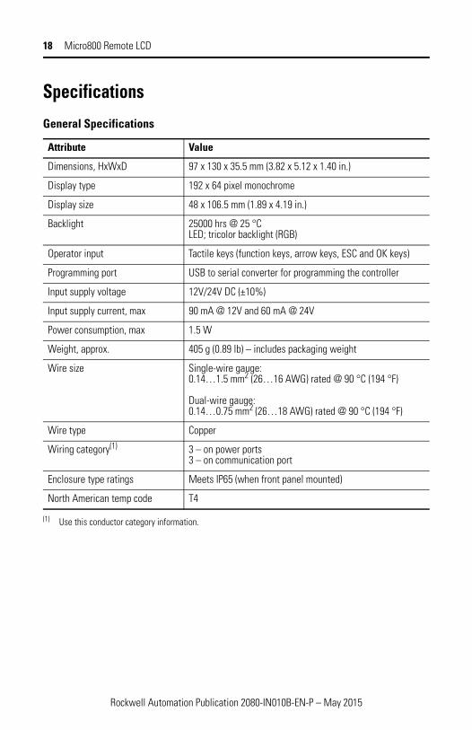
Specifications
General Specifications
Attribute Value
Dimensions, HxWxD 97 x 130 x 35.5 mm (3.82 x 5.12 x 1.40 in.)
Display type 192 x 64 pixel monochrome
Display size 48 x 106.5 mm (1.89 x 4.19 in.)
Backlight 25000 hrs @ 25 °CLED; tricolor backlight (RGB)
Operator input Tactile keys (function keys, arrow keys, ESC and OK keys)
Programming port USB to serial converter for programming the controller
Input supply voltage 12V/24V DC (±10%)
Input supply current, max 90 mA @ 12V and 60 mA @ 24V
Power consumption, max 1.5 W
Weight, approx. 405 g (0.89 lb) – includes packaging weight
Wire size Single-wire gauge: 0.14…1.5 mm2 (26…16 AWG) rated @ 90 °C (194 °F)
Dual-wire gauge: 0.14…0.75 mm2 (26…18 AWG) rated @ 90 °C (194 °F)
Wire type Copper
Wiring category(1)
(1) Use this conductor category information.
3 – on power ports3 – on communication port
Enclosure type ratings Meets IP65 (when front panel mounted)
North American temp code T4
Rockwell Automation Publication 2080-IN010B-EN-P – May 2015

Micro800 Remote LCD 19
Environmental Specifications
Attribute Value
Temperature, operating IEC 60068-2-1 (Test Ad, Operating Cold),IEC 60068-2-2 (Test Bd, Operating Dry Heat),IEC 60068-2-14 (Test Nb, Operating Thermal Shock):-20…50 °C (-4…122 °F)
Temperature, surrounding air, max
50 °C (122 °F)
Temperature, nonoperating
IEC 60068-2-1 (Test Ab, Unpackaged Nonoperating Cold),IEC 60068-2-2 (Test Bb, Unpackaged Nonoperating Dry Heat),IEC 60068-2-14 (Test Na, Unpackaged Nonoperating Thermal Shock):-30…80 °C (-22…176 °F)
Relative humidity IEC 60068-2-30 (Test Db, Unpackaged Damp Heat):5…95% noncondensing
Vibration IEC 60068-2-6 (Test Fc, Operating):2 g @ 10…500 Hz
Shock, operating IEC 60068-2-27 (Test Ea, Unpackaged Shock):25 g
Shock, non-operating IEC 60068-2-27 (Test Ea, Unpackaged Shock):DIN Mount: 25 gPANEL Mount: 45 g
Emissions CISPR 11 (IEC 61000-6-4):Class A
ESD immunity IEC 61000-4-2:4 kV contact discharges8 kV air discharges
Radiated RF immunity IEC 61000-4-3:10V/m with 1 kHz sine-wave 80% AM from 80…2000 MHz10V/m with 200 Hz 50% Pulse 100% AM @ 900 MHz10V/m with 200 Hz 50% Pulse 100% AM @ 1890 MHz10V/m with 1 kHz sine-wave 80% AM from 2000…2700 MHz
Rockwell Automation Publication 2080-IN010B-EN-P – May 2015

Certifications
Certification (when product is marked)(1)
Value
c-UL-us UL Listed Industrial Control Equipment, certified for US and Canada. See UL File E322657.
UL Listed for Class I, Division 2 Group A,B,C,D Hazardous Locations, certified for U.S. and Canada. See UL File E334470.
CE European Union 2004/108/EC EMC Directive, compliant with:EN 61326-1; Meas./Control/Lab., Industrial RequirementsEN 61000-6-2; Industrial ImmunityEN 61000-6-4; Industrial EmissionsEN 61131-2; Programmable Controllers (Clause 8, Zone A & B)
C-Tick Australian Radiocommunications Act, compliant with:AS/NZS CISPR 11; Industrial Emissions
KC Korean Registration of Broadcasting and Communications Equipment, compliant with:Article 58-2 of Radio Waves Act, Clause 3
(1) See the Product Certification link at http://www.rockwellautomation.com/products/certification for Declaration of Conformity, Certificates, and other certification details.

te
88.5
mm
[3.4
8 in
]
121.5 mm [4.78 in]
Micro800 Remote LCD Cutout Templa

22 Micro800 Remote LCD
Notes:
Rockwell Automation Publication 2080-IN010B-EN-P – May 2015

Micro800 Remote LCD 23
Notes:
Rockwell Automation Publication 2080-IN010B-EN-P – May 2015

Rockwell Automation SupportRockwell Automation provides technical information on the Web to assist you in using its products. At http://support.rockwellautomation.com, you can find technical manuals, a knowledge base of FAQs, technical and application notes, sample code and links to software service packs, and a MySupport feature that you can customize to make the best use of these tools.For an additional level of technical phone support for installation, configuration and troubleshooting, we offer TechConnect support programs. For more information, contact your local distributor or Rockwell Automation representative, or visit http://support.rockwellautomation.com.
Installation AssistanceIf you experience a problem within the first 24 hours of installation, please review the information that's contained in this manual. You can also contact a special Customer Support number for initial help in getting your product up and running.
New Product Satisfaction ReturnRockwell Automation tests all of its products to ensure that they are fully operational when shipped from the manufacturing facility. However, if your product is not functioning and needs to be returned, follow these procedures.
Allen-Bradley, Rockwell Automation, Micro800, Micro820, and TechConnect are trademarks of Rockwell Automation, Inc.
Trademarks not belonging to Rockwell Automation are property of their respective companies.
United States 1.440.646.3434Monday – Friday, 8 a.m. – 5 p.m. EST
Outside United States
Please contact your local Rockwell Automation representative for any technical support issues.
United States Contact your distributor. You must provide a Customer Support case number (call the phone number above to obtain one) to your distributor in order to complete the return process.
Outside United States
Please contact your local Rockwell Automation representative for the return procedure.
Publication 2080-IN010B-EN-P - May 2015 Supersedes Publication 2080-IN010A-EN-P - December 2013 Copyright © 2015 Rockwell Automation, Inc. All rights reserved.