Embed Size (px)
Citation preview

MFCs (Microbial Fuel Cells)
RET, Summer 2009
John A. Bogucki
Clay High School
South Bend, Indiana

Microbial Fuel Cells
Use bacteria to convert organic and
inorganic waste materials into electricity
Electrical energy in the form of
electrons are generated by the normal
metabolic activity of the bacteria in
oxidation-reduction reactions

Microbial Fuel Cells: A brief overview
COD
COD
H+
e-
H+ H+
H+
e- e-
e-
O2
O2
H2O
Proton Exchange Membrane
Anode
Anode
Cathode
Cathode
COD =
Organic Matter
Electrochemically-
active biofilm PRODUCE ELECTRICITY WHILE REMOVING ORGANIC MATTER!

MFCs function by
Converting energy available in the
substrate directly into electricity
This is achievable when bacteria switch
from the natural electron acceptor, such
as oxygen or a nitrate, to an insoluble
acceptor, such as the MFC anode

4 Components of an MFC
1. Anode
2. Cathode
3. Electrolyte
4. Proton Exchange
Membrane

1. Anode – negative electrode
Anodophilic bacteria colonize the surface
of the anode and form a “biofilm” on it
They are electrode-reducing organisms
They release electrons to the anode

2. Cathode – positive electrode
• Some MFCs utilize a biotic cathode while others utilize an abiotic cathode.
• Cathodophilic bacteria can colonize the surface of the Cathode and form a “biofilm” on it creating a biocathode
• These are electrode-oxidizing organisms
3. Electrolyte – aqueous solution
For each electron produced, a
proton must be conducted to the
cathode through the electrolyte to
sustain the current
4. Use of a PEM
PEM = Proton Exchange Membrane
• To separate the catholyte from the anolyte
• Keeps chemicals and materials other than
protons from reaching the cathode
MFC Power Generation
Maximizing power generation in MFCs
requires innovative flow patterns and
electrode orientations that minimize
resistance
MFCs have produced up to 1 kW/m3 on a
bench scale, but no one has developed a full
scale system yet.
MFCs are being constructed using a variety of materials and configurations
1. Traditional H-shaped
2. Square or Box type
3. Tubular
4. Other designs
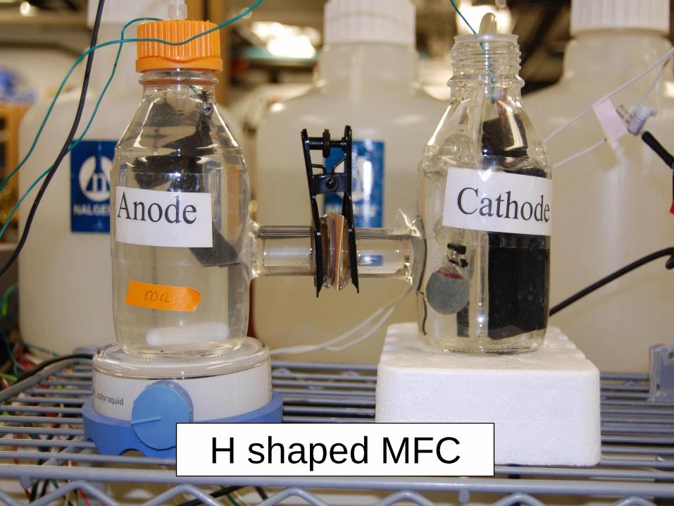
H shaped MFC
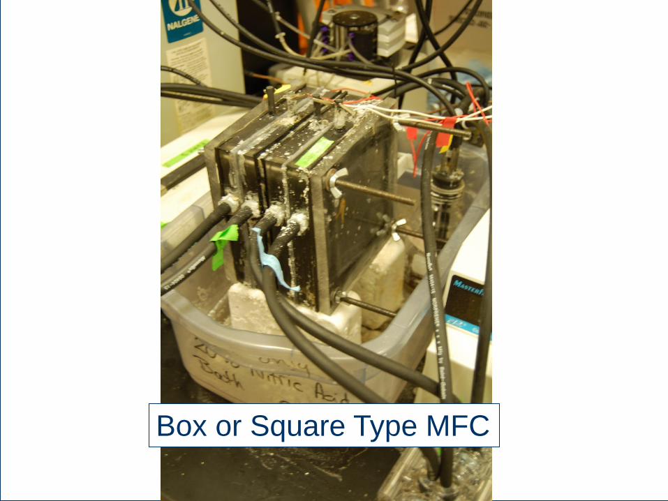
Box or Square Type MFC
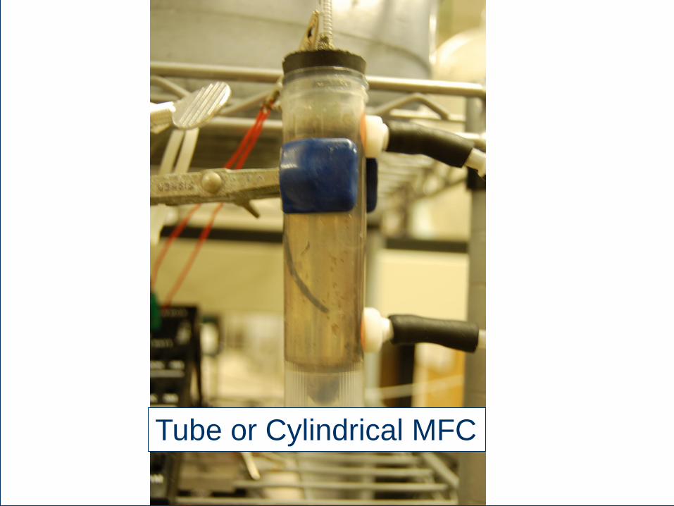
Tube or Cylindrical MFC
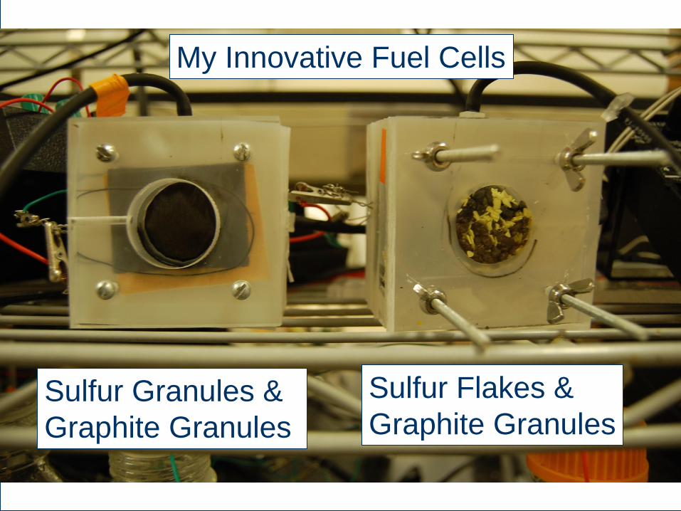
Sulfur Granules &
Graphite Granules
Sulfur Flakes &
Graphite Granules
My Innovative Fuel Cells
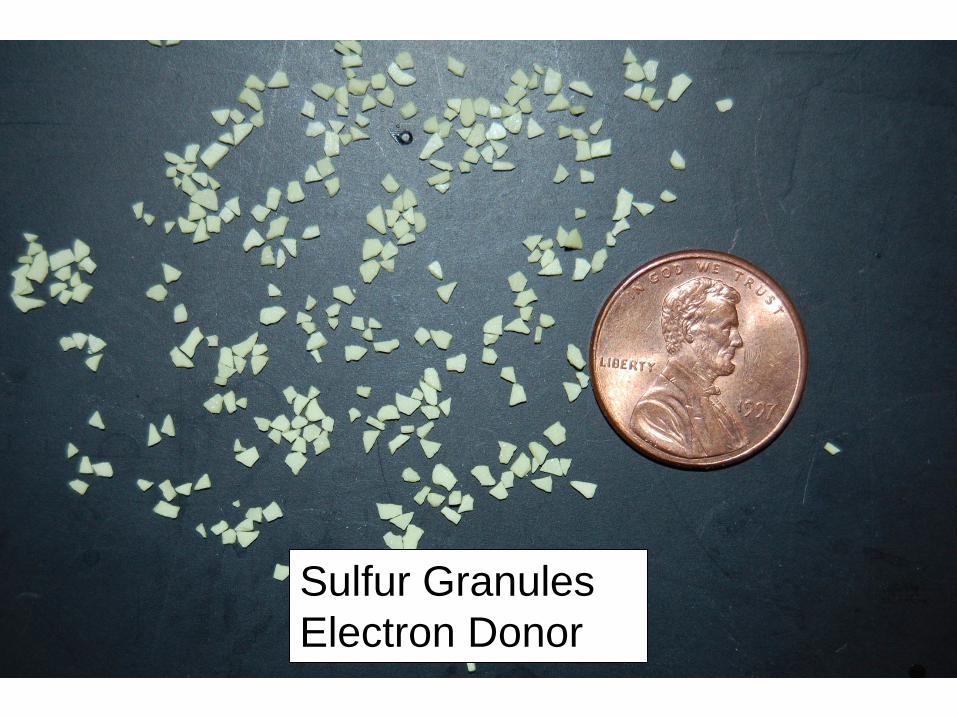
Sulfur Granules
Electron Donor
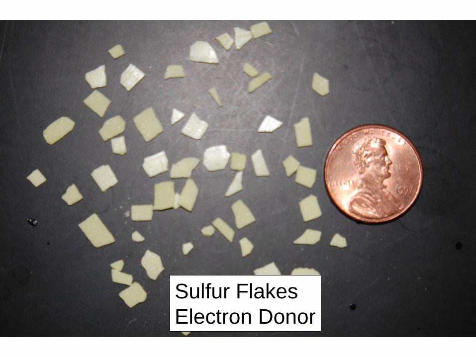
Sulfur Flakes
Electron Donor
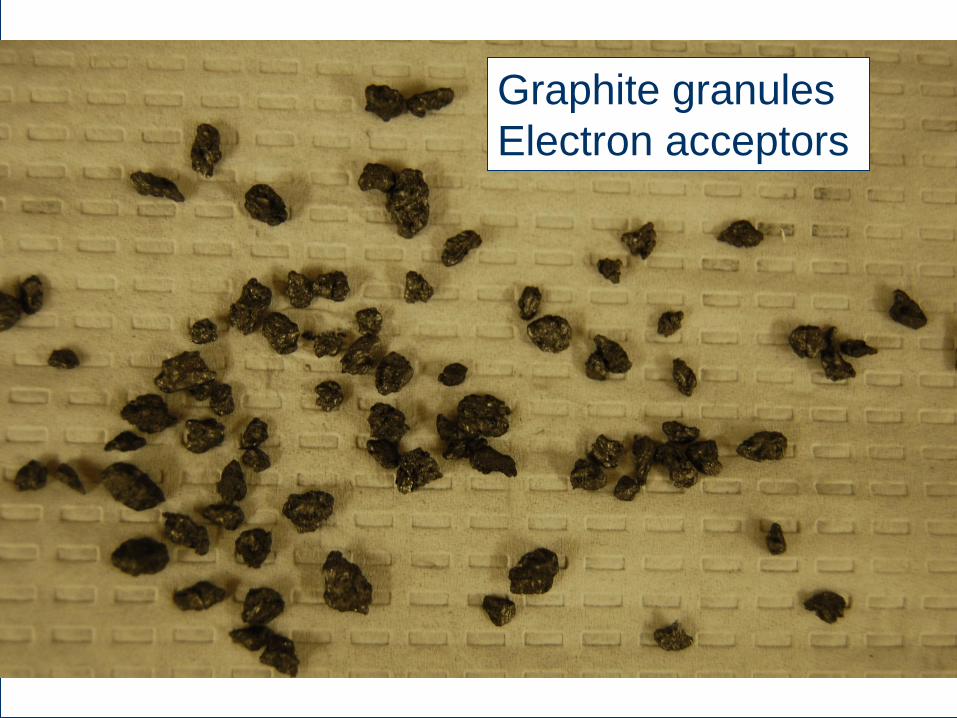
Graphite granules
Electron acceptors
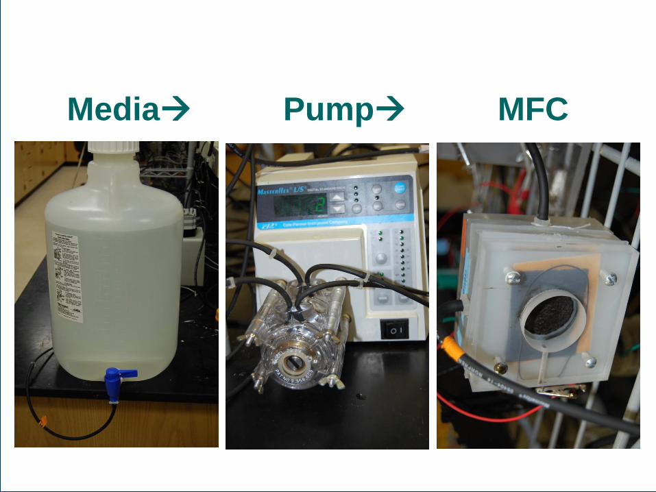
Media Pump MFC
Uses of MFCs
1. Waste water treatment
2. Removal of specialized contaminants
(like Perchlorates)
3. Powering Sensors
Advantages of Using Sulfur
1. Creates a bacterial battery
2. Doesn’t need to be constantly
replenished
3. Sulfur is plentiful and inexpensive


Layered Sulfur Based MFC Design
Proton Exchange Membrane
Anode Cathode
Air Sulfur and
Graphite
(PEM)

Sulfur MFC's
0
2
4
6
8
10
0 10 20 30 40 50
time in days
su
lfate
in
mg
/L
MFC-EJ
MFC-BE
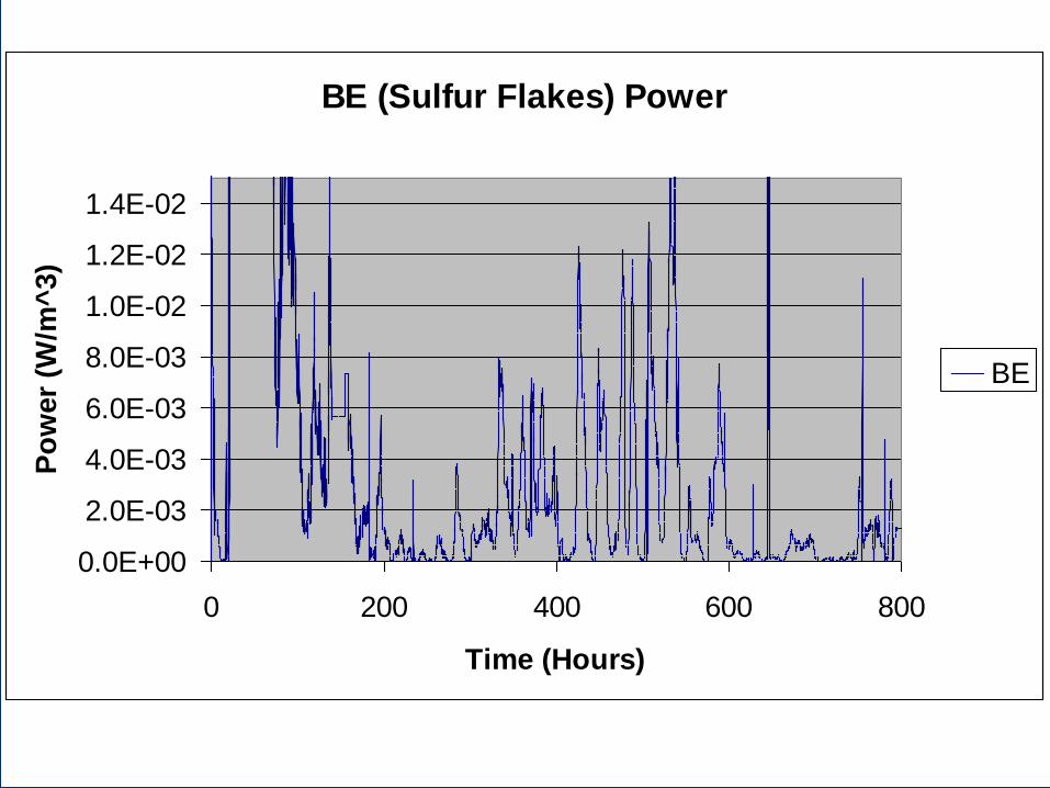
BE (Sulfur Flakes) Power
0.0E+00
2.0E-03
4.0E-03
6.0E-03
8.0E-03
1.0E-02
1.2E-02
1.4E-02
0 200 400 600 800
Time (Hours)
Po
wer
(W/m
^3)
BE
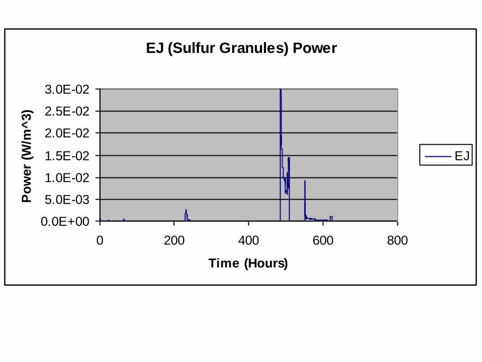
EJ (Sulfur Granules) Power
0.0E+00
5.0E-03
1.0E-02
1.5E-02
2.0E-02
2.5E-02
3.0E-02
0 200 400 600 800
Time (Hours)
Po
wer
(W/m
^3)
EJ
Caitlyn Shea

Dr. Robert “Rob” Nerenberg